EP0712298B1 - Flossing equipment - Google Patents
Flossing equipment Download PDFInfo
- Publication number
- EP0712298B1 EP0712298B1 EP94924112A EP94924112A EP0712298B1 EP 0712298 B1 EP0712298 B1 EP 0712298B1 EP 94924112 A EP94924112 A EP 94924112A EP 94924112 A EP94924112 A EP 94924112A EP 0712298 B1 EP0712298 B1 EP 0712298B1
- Authority
- EP
- European Patent Office
- Prior art keywords
- floss
- spool
- take
- trigger
- housing
- Prior art date
- Legal status (The legal status is an assumption and is not a legal conclusion. Google has not performed a legal analysis and makes no representation as to the accuracy of the status listed.)
- Expired - Lifetime
Links
- 241000628997 Flos Species 0.000 claims description 120
- 230000007246 mechanism Effects 0.000 claims description 43
- 230000037431 insertion Effects 0.000 claims 1
- 238000003780 insertion Methods 0.000 claims 1
- 230000000994 depressogenic effect Effects 0.000 description 12
- 230000000881 depressing effect Effects 0.000 description 10
- 230000000694 effects Effects 0.000 description 5
- 230000009471 action Effects 0.000 description 4
- 230000008901 benefit Effects 0.000 description 4
- 238000011109 contamination Methods 0.000 description 4
- 210000003811 finger Anatomy 0.000 description 4
- 238000004804 winding Methods 0.000 description 4
- 210000005224 forefinger Anatomy 0.000 description 3
- 229910052751 metal Inorganic materials 0.000 description 3
- 239000002184 metal Substances 0.000 description 3
- 210000003813 thumb Anatomy 0.000 description 3
- 238000004140 cleaning Methods 0.000 description 2
- 230000006835 compression Effects 0.000 description 2
- 238000007906 compression Methods 0.000 description 2
- 230000008030 elimination Effects 0.000 description 2
- 238000003379 elimination reaction Methods 0.000 description 2
- 239000000463 material Substances 0.000 description 2
- 239000004033 plastic Substances 0.000 description 2
- 229920003023 plastic Polymers 0.000 description 2
- 238000003860 storage Methods 0.000 description 2
- 238000006467 substitution reaction Methods 0.000 description 2
- XLYOFNOQVPJJNP-UHFFFAOYSA-N water Substances O XLYOFNOQVPJJNP-UHFFFAOYSA-N 0.000 description 2
- 239000004677 Nylon Substances 0.000 description 1
- 238000005299 abrasion Methods 0.000 description 1
- 229910052782 aluminium Inorganic materials 0.000 description 1
- XAGFODPZIPBFFR-UHFFFAOYSA-N aluminium Chemical compound [Al] XAGFODPZIPBFFR-UHFFFAOYSA-N 0.000 description 1
- 238000013459 approach Methods 0.000 description 1
- 230000005540 biological transmission Effects 0.000 description 1
- 238000005266 casting Methods 0.000 description 1
- 230000001419 dependent effect Effects 0.000 description 1
- 230000003993 interaction Effects 0.000 description 1
- 150000002739 metals Chemical class 0.000 description 1
- 238000000034 method Methods 0.000 description 1
- 230000007935 neutral effect Effects 0.000 description 1
- 229920001778 nylon Polymers 0.000 description 1
- 238000004806 packaging method and process Methods 0.000 description 1
- 230000002093 peripheral effect Effects 0.000 description 1
- 229920000728 polyester Polymers 0.000 description 1
- 229920000642 polymer Polymers 0.000 description 1
- 238000004513 sizing Methods 0.000 description 1
- 229910001220 stainless steel Inorganic materials 0.000 description 1
- 239000010935 stainless steel Substances 0.000 description 1
Images



Classifications
-
- A—HUMAN NECESSITIES
- A61—MEDICAL OR VETERINARY SCIENCE; HYGIENE
- A61C—DENTISTRY; APPARATUS OR METHODS FOR ORAL OR DENTAL HYGIENE
- A61C17/00—Devices for cleaning, polishing, rinsing or drying teeth, teeth cavities or prostheses; Saliva removers; Dental appliances for receiving spittle
- A61C17/16—Power-driven cleaning or polishing devices
-
- A—HUMAN NECESSITIES
- A61—MEDICAL OR VETERINARY SCIENCE; HYGIENE
- A61C—DENTISTRY; APPARATUS OR METHODS FOR ORAL OR DENTAL HYGIENE
- A61C15/00—Devices for cleaning between the teeth
- A61C15/04—Dental floss; Floss holders
- A61C15/046—Flossing tools
-
- A—HUMAN NECESSITIES
- A61—MEDICAL OR VETERINARY SCIENCE; HYGIENE
- A61C—DENTISTRY; APPARATUS OR METHODS FOR ORAL OR DENTAL HYGIENE
- A61C15/00—Devices for cleaning between the teeth
- A61C15/04—Dental floss; Floss holders
- A61C15/046—Flossing tools
- A61C15/047—Flossing tools power-driven
Definitions
- the present invention relates to a flossing device according to the preamble of claim 1.
- a flossing device of this type is disclosed in US-A-3 746 017.
- the floss take-up spool has a large flange which is provided with notches equally spaced around its periphery.
- a suitable spring is provided to engage the notches as the floss take-up spool is rotated to act as a ratchet to prevent the rotation of the floss take-up spool in one direction but permit rotation of the spool in the other direction.
- the large flange extends slightly outwardly of the housing through a slot to permit rotation of the floss take-up spool as required during use of the flossing device.
- the floss supply spool has a flange which is provided with notches around its periphery to permit a manually operable lock and release cog to be inserted into or released from the notches to lock the floss supply spool against rotation or to permit the rotation of the spool to dispense floss.
- the floss take-up spool has to be rotated by rotating the flange of the floss take-up spool by means of a thumb or finger. This may be awkward, particularly when the thumb or finger is wet.
- the object of the invention is to provide an improved flossing device the floss take-up spool of which can be easily rotated to advance and tension the floss.
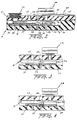
- Fig. 1 is an exploded perspective view of a manual dental flossing device 10 comprised of a handle formed from a top housing 12 and a bottom housing 14 containing a uniquely-arranged gear train, generally designated by reference numeral 16, which is operated by a spring-loaded trigger mechanism 18 protruding laterally from the bottom housing.
- Manually depressing the trigger mechanism 18 is operable to partially rotate an input gear 20, co-rotatably mounted to the trigger, which in turn counter-rotates a transfer gear 22 while indexing it into meshing contact with a take-up spool drive gear 24.
- the take-up spool drive gear 24 is rotatable with gear 22 in one direction only, i.e., to wind preferably-used floss onto a take-up spool 26 mounted on the same shaft 27 as gear 24, and is located advantageously above top housing 12.
- a floss-supply spool 29, also located atop housing 12 is simultaneously rotated counter-clockwise in an unwinding direction as a result of meshing contact between a floss-supply spool drive gear 30, mounted to rotate the supply spool, with the input gear 20, after the input gear has initially rotated to index the transfer gear into meshing contact with the take-up spool gear.
- the bottom housing 14 in the preferred embodiment is formed with an upward-facing open cavity 38 defined by a bottom wall 40 and upwardly-projecting sides 42a, 42b, 42c, 42d, 42e and 42g.
- Gear train 16 is disposed within cavity 38 before being covered by the top housing 12 which is actually in the form of an elongated cover plate 44 extending rearwardly from the fork 36.
- this plate 44 is formed with through-holes adapted to receive correspondingly-aligned posts projecting upwardly from bottom 40 along the inner surfaces of side walls 42a-42c to provide for releasable securement of the top plate to the bottom housing.
- screwed connections may be provided in place of or with these alignment post connections.
- the trigger mechanism 18 is a substantially-flat, relatively thin plate-shaped member having a profiled side edge in plan view which is mounted in an intermediate portion of the gear train housing cavity 38 on a trigger pin 46 having a lower end rotatably supported in bottom wall 40.
- An upper end 48 of pin 46 projects upward from a center pivot or crank portion 50 of the trigger 18 to be rotatably received in a through hole 52 formed in the top cover plate 44 of housing 12.
- the input gear 20 is also mounted for co-rotation with trigger 18 on the same vertical pin 46 and extends horizontally in parallel relation with the bottom surface of the trigger plate adjacent the cavity bottom wall 40.
- the trigger pin 46 thus defines a common vertical axis of rotation for both the trigger plate and the input gear 20 co-rotatable therewith.
- a distal portion 52 of the trigger mechanism 18 projects radially from the center portion 50 to protrude laterally outwardly from a slot 54 formed in an upper edge of one of the longitudinally-extending bottom cavity side walls 42c to define the manually-depressible trigger protruding laterally from the bottom housing 14.
- the forward extent of this distal trigger portion 52 is defined by an inclined surface 56 which extends outwardly and rearwardly from a point within the cavity 38, through the slot 54 to terminate at a point of intersection 58 outside the bottom housing 14 with an oppositely-inclined distal portion 60 of the trigger which projects rearwardly towards the back of the slot 54 to re-enter the cavity.
- the front surface 56 of the depressible trigger portion 52 is normally biased in a clockwise direction into contact with the front edge 54a of the slot 54 with a leaf spring 62 having a sprung wire portion 64 projecting into a slot 66 formed in a rearwardly-projecting part 68 of the trigger center portion 50 located aft of trigger pin 46 diametrically opposite the front surface 54.
- This sprung wire portion 64 extends rearwardly from a coiled spring portion 70 would around a stationary vertical support pin 72 projecting upwardly from the cavity bottom wall 40 at a location immediately adjacent an intermediate portion of the cavity side wall 42b opposite the slotted wall 42c.
- the forward vertical edge 54a of the slot 54 thus acts as a stop for the trigger portion 52 when it- is spring-biased to its normally outwardly-protruding position.
- the rearwardly extending distal portion 60 of the trigger 18 formed between the center pivot portion 50 and the manually depressible portion 52 is formed with a slot 74 which is provided to receive an intermediate portion 76 of the vertical floss supply spool mounting shaft 78 extending between the floss supply spool drive gear 30 (located elevationally below the trigger plate) and the bottom surface of the top cover plate 44.
- This slot 74 therefore provides clearance between the trigger plate, as it is manually depressed, and the floss supply spool mounting shaft 78 and gear 30 to result in a compact gear train arrangement.
- a lower end (not shown) of the floss supply spool shaft 78 is rotatably received in a hole 80 formed in the cavity bottom 40.
- the intermediate portion 76 of the shaft 78 is a larger diameter portion rotatably received in a through hole 82 formed in the top cover plate 44.
- This larger diameter portion projects upwardly into a cylindrical recess 84 in the top plate upper surface 44 adapted to receive the floss supply spool 29.
- the upper end of this larger diameter shaft portion 76 is slotted at 86 to receive a key (not shown) for securing the floss supply spool 29 to the shaft 76 to ensure co-rotation therewith.
- the floss supply spool 29 is easily detached from the upper end 78 of the supply spool shaft 76. This will advantageously allow for easy and rapid replacement of an empty floss supply spool with a fresh spool.
- the input gear 20 is co-rotatably mounted to the trigger pin 46 which defines a vertical axis of rotation or pivot for both the trigger 18 and the input gear.
- This input gear 20 is co-elevational and in meshing contact with the floss supply spool drive gear 30 located immediately rearwardly adjacent thereto.
- the take-up spool drive gear 24 also extends in the same horizontal plane as the gears 20,30, immediately adjacent to the cavity bottom wall 40, and is spaced forwardly from the input gear 20. More specifically, the take-up gear 24 is co-rotatably mounted on the vertical take-up shaft assembly 27 having a lower end projecting below the gear 24 and which is rotatably received in a hole 89 formed in the cavity bottom wall 40.
- a portion of the shaft 27 projecting above the gear 24 is formed with a ratchet portion 90 co-rotatably mounted to the take-up shaft to allow for shaft rotational movement in the take-up direction only of the spool 26 as a result of engagement with annular ratchet portion 92 fixedly mounted to project from a lower surface of the top cover plate 44 into the cavity 38.
- This annular ratchet portion 92 is formed with a series of circumferentially arranged internal ratchet teeth 94 which are stationary and engage the teeth 96 of the rotatable ratchet portion 90 to lock up both the take-up spool 26 and take-up spool drive gear 24 to prevent undesirable reverse rotation thereof in an unwinding direction.
- the upper end of the take-up spool mounting shaft 27 projects upwardly from the one-way ratcheted clutch mechanism 90 through a vertical through-hole 98 formed in the top cover plate 44.
- the take-up spool 26 is mounted to the upper end of this shaft 27. More specifically, the take-up spool 26 is formed with a large diameter upper cylindrical portion 100 formed with an annular groove 102 intersecting a vertical groove 104 communicating with the top surface 106 of the take-up spool. A smaller diameter portion 108 of the take-up spool 26 is formed beneath the larger diameter portion 100 and is also located above the top surface of the cover plate 44.
- the leading end of the fresh floss is preferably first wrapped for several turns into the annular groove 102 with the terminal end then being led into the vertical slot 104 (the remaining projecting floss end then being cut) to securely anchor the floss to the take-up spool 26.
- the floss may also be wrapped around or stored on the small diameter portion 108.
- take-up spool 26 in the winding (i.e., counter-clockwise) direction through the interaction of the input gear 20 and the transfer gear 22 meshing with take-up gear 24 which allows the user to selectively index the spent floss from the space 32, along the left-hand prong 34a and eventually onto the take-up spool 26.
- the input gear 20 advantageously performs the additional functions of tensioning the floss as a result of reversely rotating the supply spool gear 30 through a small arcuate interval, and thereby the supply spool 26 during spring loaded return of the trigger mechanism 18, and then remains in meshing contact with the supply gear to prevent the supply spool from rotating until the trigger is next depressed, it is important that the input gear be disengaged from the take-up spool drive gear 24 when the trigger is released.
- the transfer gear 22, which is always in meshing contact with the input gear 20, is mounted on a vertically extending support pin 110 which is tiltable between first and second positions (in relation to a vertical axis) in and out of meshing contact with take-up gear 24. In the first position (FIG.
- the transfer gear 22 is biased out of meshing contact with the take-up spool drive gear 24.
- This biasing is achieved by means of a profiled cam surface 112 formed in a portion 114 of the trigger plate which projects forwardly from the center or pivot portion 50.
- This cam surface 112 is in co-elevational alignment with a small diameter cylindrical cam follower 116 which is mounted on the transfer gear mounting pin 110 above the transfer gear 22 for co-rotation therewith.
- the upper end 118 of this pin 110 projects above the cam follower 116 and is received in an elongated slotted opening 120 formed in the cover plate 44 of the top housing 12.
- This unique de-clutchable transfer gear mechanism operates as follows. As the spring-loaded trigger 52 is depressed against the bias of spring 64, the cam surface 112 is retracted (rotated counter-clockwise) from the cam follower 116, with co-rotation of the input gear 20 immediately tilting the transfer gear support pin 110 from the first tilted position (Fig. 3) to a second tilted position (Fig. 4) where the transfer gear travels into meshing contact with the take-up spool drive gear 24.
- the input gear 20 is formed with a smooth peripheral portion 20' of predetermined arcuate extent, devoid of gear teeth, which is positioned to prevent initial rotation of the supply spool gear 30 until the input gear has indexed the transfer gear 22 into initial contact with the take-up gear 24.
- the teeth on gear 20 preceding the smooth portion 20' are in meshing contact with the teeth on supply spool gear 30 when the trigger 18 is not depressed and therefore locks the supply spool against rotation.
- These immediately preceding teeth move out of meshing contact with the gear 30 as trigger 18 is initially depressed and smooth portion 20' slides past the supply spool teeth to delay rotation of the supply spool in the aforesaid manner. This prevents feeding of floss until the take-up spool gear 24 engages transfer gear 22 to co-rotate with the supply spool.
- the manual dental flossing device 10 of the present invention possesses numerous advantages over prior art flossers of which we are aware. Locating the take-up spool 26 outside of the gear train housing 12,14, for example, advantageously avoids contamination within the housing by used floss and results in easy cleaning with water to prevent the occurrence of an unhygienic situation.
- the keyed mounting 86 of the supply spool 29 also outside the housing 12,14 advantageously allows an empty supply spool to be easily detached from its keyed shaft 76 to facilitate rapid replacement with a fresh supply spool.
- Re-threading of the floss in the event of breakage or replacement to quickly reestablish the floss circuit is also easy.
- the floss is placed within a slotted opening 125 formed in the side of a cylindrical guide 127 mounted on the top cover plate 44 forwardly from the take-up spool 26 and on the supply side of the circuit.
- This slot 125 has the effect of spacing the fresh floss from the take-up spool 26 while aligning the fresh floss with an upwardly directed groove 130 extending along the length of the supply prong 34b of the fork 32 in the top surface thereof.
- This floss is then stretched across the space 32 between the prongs 34a,34b by being disposed within a pair of short, transversely extending slots 132 respectively formed in the front ends of the prongs.
- the floss is then threaded through an upwardly directed slot 130 formed in the top surface of the take-up prong 34a.
- the leading end of the floss is then wound onto the take-up spool 26 in the manner described above and any remaining portion of the leading end extending from the take-up spool can then be cut.
- the feature of providing a one-way clutch on the take-up spool 26 advantageously prevents undesirable reverse or clockwise rotation in the unwinding direction. Furthermore, since the supply spool gear 30 is in constant mesh with the input gear 20 (except upon initial depressing of trigger 18 as noted above), this has the added advantage of preventing undesirable rotation of the supply spool in the unwinding or counter-clockwise direction unless the manual trigger 18 is intentionally depressed to feed the floss. That is, the supply spool gear 30 is positively locked against inadvertent or uncontrolled rotation when the trigger 18 is not being depressed, i.e., during flossing.
- the material of which the flossing device 10 is made may include multiple plastics, nylon, polyester, other polymers, and combinations of the above. Aluminum, stainless steel, and other metals may also be used.
- the important features of the present invention with respect to each of the manual and mechanical embodiments primarily relate to the advantageous placement of the take-up spool outside of the housing while confining the gear train assembly therein to avoid an unhygienic situation, while allowing for easy threading or re-threading of the floss to establish the floss circuit. This is important when considering that the floss will typically break at least one during a daily flossing regimen as a result of abrasion or breaking due to contact with tight spaces. To encourage use of the flossing devices of these inventions, it is therefore imperative that the user be easily able to re-establish the floss circuit with minimal hassle.
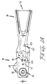
- FIG. 5 is an exploded perspective view of a preferred embodiment of a manual dental flossing device 1000 comprised of a handle formed from a top housing 1002 and a bottom housing or closure plate 1004 containing a uniquely arranged spring-loaded trigger mechanism, generally designated by reference numeral 1006, protruding laterally from between the housings.
- Manually depressing the trigger mechanism 1006 is operable to partially rotate a take-up spool drive wheel 1008 in one direction A only through advancement of a driving pawl 1010, attached to the trigger, into contact with ratchet teeth 1012 (FIG. 7) formed on the take-up spool drive wheel 1008.
- Wheel rotation winds preferably used floss 1014 onto a take-up spool 1016, co-rotatably mounted on the same shaft axis 1018 as the take-up wheel 1008, and located advantageously above the top housing 1002.
- a floss supply spool 1020 advantageously located in an interior compartment 1022 disposed in the back end of the top housing 1002, is simultaneously rotated in an unwinding direction B as a result of overriding a slip clutch for similar ratchet mechanism 1025 as discussed more fully below.
- a ratchet finger or stop pawl 1027 advantageously prevents reverse rotation of the floss take-up spool drive wheel 1008 so that the floss supply circuit remains highly tensioned to avoid slack in the floss in space 32.
- the top housing 1002 is in the form of an elongated substantially flat cover plate extending rearwardly from the curved fork 36. Unlike top housing 12 in the flossing device 10 described above, however, the top housing 1002 in the preferred embodiment features a covered cylindrical rear housing 1030 with interior cavity 1022 adapted to contain floss supply spool 1020.
- the floss supply spool housing cavity 1022 is defined by a circular bottom wall 1032 and a cylindrical side wall 1034 having a diameter which is greater than the diameter of a full floss supply spool (FIGS. 5 and 6).
- Side wall 134 terminates in an upward facing circular opening which is selectively covered (FIG. 7) or uncovered (FIG.
- a stop ridge 1040 subtending a predetermined angular interval of less than 180° is formed partly around the circular opening to act as an abutment when the cover plate is pivoted into the closed position (FIG. 7).
- a groove 1042 (FIG. 6) formed in the stop ridge 1040 allows the passage of floss from the supply spool 1020 along the top surface 1002a of the housing 1002 to establish the floss circuit around fork extension 36.
- a rounded protuberance 1044 projecting downward from the lower surface of cover 1036 acts as a locking detent to maintain the cover in closed position.
- the floss take-up spool 1016 constitutes the sole structure in the floss supply circuit which is located outside the housings 1002,1004 to advantageously avoid contamination within the housings by used floss and to enable easy cleaning with water to prevent the occurrence of an unhygienic situation.
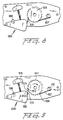
- FIG. 7 is a bottom plan view of flossing device 1000 with the bottom housing or cover 1004 removed to enable viewing of the trigger mechanism 1006 and take-up spool drive wheel 1008 located within the compartment formed between the top and bottom housings.
- Solid lines 1046,1046' depict the forwardmost and rearwardmost extent of the bottom cover plate 1004.
- bottom cover 1004 is formed with a bottom wall 1050 with upwardly projecting sides 1052 and a cutout 1054 formed in one of the sides through which the trigger 1006 extends into the FIG. 7 undepressed condition.
- Bottom cover 1004 may be secured to top cover 1002 with screws 1055.
- the take-up spool supply wheel 1008 is located within an interior compartment defined by the parallel interior faces 1002b, 1050a of the top and bottom walls formed in the associated housings and is rotationally supported through upper and lower shaft projections 1056 and 1058 respectively received within aligned through holes 1060 and 1062 formed in the top and bottom walls.
- the lower shaft projection 1058 terminates within the lower throughbore 1062 while the upper shaft projection 1056 extends outwardly from the top wall 1002a into press-fitting non-rotational engagement with a downwardly projecting shaft stub 1064 in the take-up spool 1016. In this manner, rotation of the take-up spool drive wheel 1008 is transmitted to the take-up spool 1016 as discussed infra.
- the trigger mechanism 1006 is used to incrementally rotate the take-up spool drive wheel 1008 by advancing driving pawl 1010 into meshing contact with one of ratchet teeth 1012 upon depressing the trigger.
- the trigger 1006 is a triangular or sector shaped member, preferably of uniform thickness, having a rearwardly projecting apex 1066 pivotally secured within the compartment via upper and lower pin projections 1068 received in aligned throughbores 1070 respectively formed in the top and bottom walls 1002a,1050.
- the trigger includes a manually depressible portion 1072 protruding outwardly through the cutout 1054 into its outwardmost neutral position (FIG.
- a compression spring 1074 having opposite ends in respective abutment with the trigger and a fixed spring rest 1076 attached to the interior face 1002b of the top housing wall 1002a. More specifically, the fixed spring rest 1076 and the opposing surface defining the interior triangular side 1078 of the trigger 1006 respectively support a pair of projections 1080 respectively received within the spring ends to maintain the spring 1074 in its proper position.
- the outwardmost extent of the trigger 1072 is defined via contact between a pin 1084 projecting downwardly from the trigger (intermediate the pivot pin 1068 and spring rest 1080) engaging the outer end of an elongate slot 1086 formed in the interior surface 1002b of the top wall 1002a.
- driving pawl 1010 enters into meshing contact with one of the ratchet teeth 1012 of take-up spool drive wheel 1008 to rotate same through a predetermined arcuate interval.
- the pawl 1010 may be integrally formed with the forward distal portion 1082 of the trigger 1006 to have a distal end 1010a adapted to contact the gear teeth 1012.
- distal end 1010a is advanced into pushing contact with a generally radially extending wall 1012a of a tooth 1012 to rotate wheel 1008 about its axis of rotation 1018 (FIG. 9).
- driving pawl 1010 is disclosed as being integral with trigger 1006, other materials and configurations can be used in substitution therefor.
- the pawl 1010 may be made as a separate member.
- pawl 1010 may be substituted with a rack attached to trigger 1006 and having a series of rack teeth adapted to mesh with teeth formed in a take-up spool drive gear or with the ratchet teeth of wheel 1008.
- Trigger release allows the compressed spring 1074 to bias the trigger 1006 back to its home position depicted in FIGS. 7 and 8.
- the distal end 1010a of the driving pawl 1010 travels out of driving engagement with one of ratchet teeth 1012 where it will ride over the generally circumferentially extending inclined wall 1012b of the trailing ratchet tooth 1012.
- undesirable reverse rotation of the take-up spool drive ratchet 1008 during trigger release is advantageously prevented by means of stop pawl 1027 functioning as a one-way clutch mechanism. As best depicted in FIG.
- this stop pawl 1027 has one end secured to a stationary support projection 1102 formed in the forward portion of the top wall interior face 1002b.
- This pawl 1027 projects rearwardly and has a rear distal end 1104 which will positively engage with the take-up spool drive teeth 1012 during trigger release.
- this distal end 1104 engages a wall 1012a to prevent reverse rotation of the ratchet 1008 as the distal end 1010a of the driving pawl rides up and over the teeth during trigger release.
- trigger depressing FIG.
- the distal end 1104 of the stop pawl 1027 is configured to ride up and over the ratchet tooth wall 1012b as the ratchet is advanced by the driving pawl 1010 in the winding direction of the take-up spool 1016.
- the stop pawl 1027 as used in the preferred embodiment defines a very simple but reliable one-way clutch mechanism to prevent reverse rotation of the take-up spool drive wheel 1008.
- a ratchet mechanism comprised of a driving pawl 1010 and stop pawl 1027 in the preferred embodiment avoids the need for multiple gears as employed in the FIG. 1 embodiment of dental flossing device 10. This in turn allows a large diameter take-up wheel 1008 to be used which, in combination with appropriate sizing and placement of trigger 1006 and driving pawl 1010, will result in sufficient mechanical advantage to enable individuals with weak hand grips to exert enough pressure to depress trigger 1006 without compromising floss tension.
- floss supply spool 1020 is advantageously located within interior compartment 1022 disposed in the rearwardmost portion of the top housing 1002. This interior placement advantageously isolates the fresh spool from possible contamination with spent floss accumulating on the take-up spool 1016 and also prevents undesirable contact with the user's hand during gripping and manipulation of the dental flossing device 1000, as tended to occur with the dental flossing device 10 discussed, supra.
- the user can now place the palm portion of their hand, or the base of their forefinger, on the upper surface of closed cover plate 1036 while allowing their thumb and forefinger to rest against the opposing side surfaces of the top and bottom housings 1002,1004, with the trigger 1006 being depressed by the forefinger, all without contacting the floss on the supply spool or within the circuit.
- the floss supply spool 1020 is preferably in the form of a cylindrical spool 1110 (e.g., plastic) on which fresh floss 1112 is wound.
- the supply spool 1020 is easily mounted by the user on supply spool support shaft arrangement 1025 projecting upwardly in the storage compartment 1022 from the bottom wall 1032 thereof.
- this support shaft arrangement 1025 is formed with a key 1115 adapted to interfit with a vertical key guide 1117 formed on the inner cylindrical surface of the supply spool 1110.
- the floss supply spool is easily detached from the support shaft to advantageously allow for easy and rapid replacement of an empty floss supply spool with a fresh spool.
- the present invention allows for use of pre-wound replacement spools of floss which are specially made so that the supply spools 1110 are keyed or otherwise adapted to easily interfit onto the supporting shaft arrangement 1025 for easy removal and placement thereon.
- the floss on each of these pre-wound spools is preferably evenly machine wrapped onto the supply spool 1110 with the floss leader initially contacting the supply spool preferably tied or otherwise fixed to the spool so as to maintain tension in the floss circuit as the supply spool approaches empty.
- These pre-wound supply spools may be sold together with the flosser of FIG. 5 in a kit form, or may be available for individual purchase to replenish the floss supply.
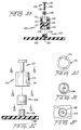
- the support shaft arrangement 1025 is formed with a lower support shaft portion 1120 fixed to the storage compartment bottom wall 1032 and an upper shaft portion 1122 formed with the keyed connection 1115 and mounted to the lower shaft portion.
- the upper surface of the lower shaft portion 1120 is formed with a series of triangular shaped teeth 1124 meshing with an array of like bottom teeth 1126 formed in a cylindrical bottom recess 1127 of the upper shaft cylindrical portion 1122.
- the lower shaft portion 1120 projects into recess 1127 for improved centering and support.
- These teeth 1124,1126 are urged into contact with each other by means of a tension spring 1128 located within an upper cylindrical recess 1130 formed in the upper shaft portion 1122.
- the lower end of the compression spring 1128 is seated against the recessed bottom wall 1132 formed in recess 1130.
- the upper end of the spring is captivated against the lower surface of a screw head 1134 of a tension adjustment screw 1136.
- the screw shank 1138 extends through both the tension spring 1128 and a through bore 1137 located between recesses 1127,1130, with the lower end 1139 in threaded engagement with a threaded bore 1140 in lower fixed shaft 1120.
- the teeth formed in the upper and lower shaft portions act as a slip clutch which enables floss 1112 to be stripped from the spool 1020 during trigger depressing (i.e., the upper teeth ride up and over the lower teeth against bias of spring 1128 during rotation of upper shaft portion 1122 on which the floss spool is mounted) while maintaining appropriate tension through the supply spool on the supply end of the floss circuit.
- screw 1136 may be rotated to adjust the tension of spring 1128 which in turn directly affects the tension in the floss circuit.
- Screw 1136 may be turned with a screwdriver.
- screw head 1134 may be suitably provided with a knurled or other type of manual gripping profile to facilitate tension adjustment.
- FIGS. 5C-5F constitute an alternate embodiment to the spring and screw adjustment mechanism depicted in FIG. 5B.
- fixed lower shaft portion 1120 is replaced with a fixed ratchet wheel 1200 integrally formed to project upward from bottom wall 1032.
- Ratchet wheel 1200 is formed with vertically extending ratchet teeth 1202 as best depicted in FIGS. 5C and 5F.
- a clutch member 1204 formed with a pair of diametrically opposed curved fingers 1206 respectively provided with a ratchet pawl 1208 at opposite distal ends thereof (FIG. 5E) is mounted for rotation on ratchet wheel 1200.
- the arrangement of ratchet teeth 1202 and pawls 1208 in engagement therewith functions as an alternative means for tensioning the supply spool and the floss circuit.
- floss supply spool 1020 is easily loaded into flossing device 1000 in the preferred embodiment by first pivoting cover 1036 into the open position of FIG. 5.
- Supply spool 1020 is then loaded by inserting the upper end of upper shaft portion 1122 into the lower end of cylindrical spool 1110 as the spool is lowered onto the support shaft arrangement 1025 with key 1115 in proper alignment with key guide 1117.
- the user grips the free end of the floss and exerts pressure to strip a length of floss from the spool against the bias of the slip clutch mechanism discussed above.
- the strip floss leader is then fed into the guide groove 1042 by simply lowering it into the open groove. At this point, cover 1036 may now be pivoted into its closed position (FIG. 7). The floss leader is then positioned around the fork 36 and the leading end of the floss is then wrapped several times around take-up spool 1016 before being secured into notch 1150 thereon. The flossing device 1000 is now ready for use.
- ratchet mechanism connected to the supply spool to cooperate with the ratchet mechanism 1008 to tension the floss
- other tensioning mechanisms are possible.
- the so-called ratchet mechanism afforded by teeth 1124, 1126 may be replaced by elimination of these teeth in favor of another type of slip clutch mechanism or, for example, a drag type of mechanism (adjustable or non-adjustable) as commonly used in spin fishing reels and bait casting reels for controlling the drag or tension of fishing line. Therefore, these teeth may be replaced, for example, with one or more synthetic or metal washers imparting friction to resist unwinding rotation of supply spool 1020.
- ratchet mechanism afforded with teeth 1124,1126 may also be replaced with other types of tensioning mechanisms, such as the elimination of the aforesaid teeth with the placement of a pin spaced away from the supply spool and extending generally parallel to the axis of rotation of the supply spool. It is believed that a couple of turns of floss around this pin may be sufficient to appropriately tension the floss in the circuit at the supply end thereof.
- forked extension 32 is also intended to cover the use of other projections extending from the housing which define a space between the projections between which floss may extend.
Landscapes
- Health & Medical Sciences (AREA)
- Dentistry (AREA)
- Epidemiology (AREA)
- Life Sciences & Earth Sciences (AREA)
- Animal Behavior & Ethology (AREA)
- General Health & Medical Sciences (AREA)
- Public Health (AREA)
- Veterinary Medicine (AREA)
- Brushes (AREA)
- Storing, Repeated Paying-Out, And Re-Storing Of Elongated Articles (AREA)
- Dental Tools And Instruments Or Auxiliary Dental Instruments (AREA)
Description
Claims (7)
- Flossing device to facilitate the insertion of floss between teeth, comprising a housing (12; 1002, 1004) with a pair of prongs (34) with grooves for guiding the floss in a circuit which spans a space (32) between the prongs, a floss supply spool (29; 1020) rotatably mounted to the housing, a floss take-up spool (26; 1016) rotatably mounted to the housing, means for rotating the floss take-up spool, a first mechanism interacting with the floss take-up spool to tension the floss during periods when the floss take-up spool is not rotated, and a second mechanism interacting with the floss supply spool and cooperating with the first mechanism to tension the floss, characterized in that the means for rotating the floss take-up spool (26; 1016) comprise a depressible trigger (18; 1006) projecting from the housing (12; 1002, 1004) and acting upon the first mechanism to advance the floss in the circuit.
- Flossing device according to claim 1, wherein the first mechanism is a first ratchet mechanism (1008, 1027) and the depressible trigger (1006) includes a driving pawl (1010) engageable with the first ratchet mechanism during actuation of the trigger.
- Flossing device according to claim 1 or 2, wherein the second mechanism is a ratchet mechanism (1025, 1120; 1200, 1204).
- Flossing device according to claim 1 or 2, wherein the second mechanism is a slip clutch mechanism or a drag type mechanism.
- Flossing device according to anyone of claims 1 to 4, wherein the floss supply spool (1020) is located in a separate compartment (1022) within the housing (1002, 1004).
- Flossing device according to claim 5, wherein the housing (1002, 1004) comprises a cover (1036) which is moveable to selectively cover and uncover the compartment (1022) for the floss supply spool (1020).
- Flossing device according to anyone of claims 1 to 6, wherein the floss take-up spool is located outside the housing.
Applications Claiming Priority (5)
| Application Number | Priority Date | Filing Date | Title |
|---|---|---|---|
| US10107193A | 1993-08-03 | 1993-08-03 | |
| US101071 | 1993-08-03 | ||
| US26793994A | 1994-07-06 | 1994-07-06 | |
| US267939 | 1994-07-06 | ||
| PCT/US1994/008737 WO1995003750A1 (en) | 1993-08-03 | 1994-08-03 | Flossing equipment and method of operation |
Publications (2)
| Publication Number | Publication Date |
|---|---|
| EP0712298A1 EP0712298A1 (en) | 1996-05-22 |
| EP0712298B1 true EP0712298B1 (en) | 2002-04-24 |
Family
ID=26797870
Family Applications (1)
| Application Number | Title | Priority Date | Filing Date |
|---|---|---|---|
| EP94924112A Expired - Lifetime EP0712298B1 (en) | 1993-08-03 | 1994-08-03 | Flossing equipment |
Country Status (7)
| Country | Link |
|---|---|
| US (2) | US5678578A (en) |
| EP (1) | EP0712298B1 (en) |
| AU (1) | AU7450494A (en) |
| CA (1) | CA2168780C (en) |
| DE (1) | DE69430480T2 (en) |
| IL (1) | IL110522A (en) |
| WO (1) | WO1995003750A1 (en) |
Families Citing this family (53)
| Publication number | Priority date | Publication date | Assignee | Title |
|---|---|---|---|---|
| IL110522A (en) * | 1993-08-03 | 2005-06-19 | Kossak Michael | Flossing equipment and method of operation |
| US7234473B1 (en) | 1998-06-01 | 2007-06-26 | Steven Nebeker Winters | Dental floss dispensers, flossing tools, and toothbrush flosser |
| US6474347B1 (en) | 1999-01-28 | 2002-11-05 | Anders Hallinder | Dental floss holder |
| AU2002211718A1 (en) * | 2000-10-13 | 2002-04-22 | Michael Kossak | Improvements to manually held dental flossers |
| CA2366330A1 (en) * | 2001-01-02 | 2002-07-02 | Michael A. Doyscher | Dental floss dispenser and applicator |
| US6920659B2 (en) | 2001-01-12 | 2005-07-26 | Water Pik, Inc. | Toothbrush |
| US6874509B2 (en) | 2001-05-18 | 2005-04-05 | Mark C. Bergman | Flossing device with advancing and tensioning mechanism |
| US6955539B2 (en) | 2001-07-12 | 2005-10-18 | Water Pik, Inc. | Characterization of motion of dual motor oral hygiene device |
| US20030106565A1 (en) * | 2001-12-12 | 2003-06-12 | Andrews Ricky Lee | Scissor-like flossing device |
| US7198487B2 (en) | 2002-12-31 | 2007-04-03 | Water Pik, Inc. | Whitening tip for dental flossing device |
| NZ525470A (en) * | 2003-04-23 | 2006-02-24 | Christopher Joseph Kernot | A dispenser for filamentary material |
| GB0312872D0 (en) * | 2003-06-05 | 2003-07-09 | Prineppi Frank J | Improvements in and relating to dental flossers |
| US20080033570A1 (en) * | 2003-08-01 | 2008-02-07 | Blitz Benjamin T | Prostatic stent placement device |
| WO2005013855A2 (en) * | 2003-08-01 | 2005-02-17 | Cook Urological, Incorporated | Implant delivery device |
| US20050252520A1 (en) * | 2004-05-17 | 2005-11-17 | Ehsan Filsouf | Flossing device with internal floss feed |
| US7475695B2 (en) * | 2004-05-17 | 2009-01-13 | Ehsan Filsouf | Flossing device with internal floss feed |
| US7156110B2 (en) * | 2004-07-14 | 2007-01-02 | Landry David H | Dental floss dispensing and tensioning device |
| CN100525728C (en) * | 2004-09-14 | 2009-08-12 | 沈仲山 | Dental floss spreader of dental floss device |
| TWM281601U (en) * | 2005-05-10 | 2005-12-01 | Jen-Chiuan Chen | Dental floss device |
| WO2007012221A1 (en) * | 2005-07-26 | 2007-02-01 | Shengfa Fan | A dental cleaner |
| WO2008075138A1 (en) * | 2006-12-21 | 2008-06-26 | Ehsan Filsouf | Flossing device with internal floss feed |
| US7882845B2 (en) * | 2007-09-20 | 2011-02-08 | Ehsan Filsouf | Flossing device with internal floss feed |
| TWI396526B (en) | 2008-05-20 | 2013-05-21 | Ind Tech Res Inst | Oral interface apparatus with negative pressure and method for maintianing oral negative pressure and collecting saliva |
| JP4808791B2 (en) * | 2009-02-05 | 2011-11-02 | 沈 仲山 | Dental floss holder |
| US20110041870A1 (en) * | 2009-08-19 | 2011-02-24 | Russell Kalbfeld | Dental flosser |
| US8671958B2 (en) | 2009-10-14 | 2014-03-18 | N. Michelle Borg | Orthodontic flosser |
| US9517118B1 (en) * | 2009-09-10 | 2016-12-13 | N. Michelle Borg | Orthodontic flosser |
| US8387629B1 (en) | 2009-10-14 | 2013-03-05 | N. Michelle Borg | Orthodontic flosser |
| US20160310246A1 (en) * | 2009-10-14 | 2016-10-27 | N. Michelle Borg | Orthodontic flosser |
| US8104487B2 (en) * | 2010-02-19 | 2012-01-31 | Richard Hardy | Dental floss holder |
| US8505557B1 (en) * | 2011-03-29 | 2013-08-13 | Charles Louis Urso | Powered dental cleaner |
| US8910643B2 (en) * | 2011-04-20 | 2014-12-16 | Ross E. Aronson | Ultrasonic manipulator of dental floss and method for operating the same |
| CN106037977B (en) | 2011-05-02 | 2018-06-29 | 沃特皮克公司 | The method for designing acoustic toothbrush |
| US9468511B2 (en) | 2013-03-15 | 2016-10-18 | Water Pik, Inc. | Electronic toothbrush with vibration dampening |
| CA2905566C (en) | 2013-03-15 | 2017-11-07 | Water Pik, Inc. | Mechanically-driven, sonic toothbrush and water flosser |
| US10238475B1 (en) * | 2014-07-18 | 2019-03-26 | N. Michelle Borg | Orthodontic flosser |
| US9510921B1 (en) | 2014-11-04 | 2016-12-06 | Charles Louis Urso | High-speed automatic dental flosser |
| HK1199686A2 (en) | 2014-11-14 | 2015-07-10 | 艾历有限公司 | Dental floss device |
| CN205568226U (en) | 2015-07-08 | 2016-09-14 | 洁碧有限公司 | Device of brushing teeth |
| US10561480B2 (en) | 2016-05-09 | 2020-02-18 | Water Pik, Inc. | Load sensing for oral devices |
| USD819276S1 (en) * | 2016-05-13 | 2018-05-29 | Russell G. Kramer | Flossing tool |
| KR101706973B1 (en) * | 2016-10-12 | 2017-02-15 | 김상한 | Dental Floss Holder which can control the tention |
| US10918467B2 (en) * | 2016-12-09 | 2021-02-16 | Mark Davidov | Disposable portable pocket fluid and floss dispenser |
| USD844997S1 (en) | 2016-12-15 | 2019-04-09 | Water Pik, Inc. | Toothbrush handle |
| USD845636S1 (en) | 2016-12-15 | 2019-04-16 | Water Pik, Inc. | Toothbrush handle |
| EP3554418B1 (en) | 2016-12-15 | 2021-06-30 | Water Pik, Inc. | Brushing device with illumination features |
| GR1009515B (en) * | 2017-07-10 | 2019-05-02 | Δημητριος Μιχαηλ Καμπουρογλου | Dual-purpose teeth-cleaning system |
| WO2019046545A1 (en) * | 2017-08-30 | 2019-03-07 | Nortman Scott D | Arbitrary motion toothbrush |
| US10948056B2 (en) * | 2017-12-23 | 2021-03-16 | Continental Automotive Systems, Inc. | Elevation mechanism for a central input selector knob |
| WO2020117040A1 (en) * | 2018-12-06 | 2020-06-11 | Lodde Marius | Device for cleaning a set of teeth and cleaning member for use therein |
| CN111388113B (en) * | 2020-03-27 | 2021-05-04 | 牡丹江医学院 | Oral Care Appliances |
| US20250381018A1 (en) * | 2024-06-12 | 2025-12-18 | Mary C. Marcella | Electronic flossing device comprising disposable flossing cartridge |
| KR102842195B1 (en) * | 2024-11-26 | 2025-08-04 | 서지담 | Dental floss dispenser |
Family Cites Families (47)
| Publication number | Priority date | Publication date | Assignee | Title |
|---|---|---|---|---|
| US1700550A (en) * | 1926-12-09 | 1929-01-29 | Ethel G Stafford | Dental floss holder |
| US3106216A (en) * | 1961-07-14 | 1963-10-08 | James B Kirby | Tooth cleaning device |
| US3340881A (en) * | 1964-09-02 | 1967-09-12 | Laverne M Cowan | Dental floss holder |
| US3472247A (en) * | 1967-04-17 | 1969-10-14 | Adolph W Borsum | Hydraulic-filament dental device |
| US3534745A (en) * | 1968-08-30 | 1970-10-20 | William A Waters | Dental tape holder for power driven tooth cleaning devices |
| US3667483A (en) * | 1970-12-14 | 1972-06-06 | James B Mccabe | Dental floss reciprocator |
| US3734107A (en) * | 1971-11-12 | 1973-05-22 | I Thierman | Dental floss tooth cleaning tool |
| US3746017A (en) * | 1972-02-14 | 1973-07-17 | J Casselman | Dental floss holder and applicator |
| US3759274A (en) * | 1973-03-12 | 1973-09-18 | C Warner | Dental instrument |
| CA1000533A (en) * | 1973-03-26 | 1976-11-30 | Irwin B. Thierman | Dental floss tooth cleaning tool |
| US3901251A (en) * | 1973-11-14 | 1975-08-26 | James A Johnston | Dental floss dispensing and manipulation systems |
| US3927687A (en) * | 1974-04-18 | 1975-12-23 | I Bruce Thierman | Combination shaft and spool structure |
| US3908677A (en) * | 1974-12-12 | 1975-09-30 | Delore A Beach | Dental floss holder |
| US4031908A (en) * | 1975-09-04 | 1977-06-28 | Ting Wen C | Dental appliance |
| USD251859S (en) | 1977-08-15 | 1979-05-15 | Johnson & Johnson | Dental flossing tool |
| US4245658A (en) * | 1979-04-09 | 1981-01-20 | Lecouturier Jacques M | Automatic flossing apparatus |
| US4235253A (en) * | 1979-05-07 | 1980-11-25 | Moore Dawne A | Electric dental flosser |
| US4319595A (en) * | 1980-01-30 | 1982-03-16 | Rex Ulrich | Dental care unit |
| US4326549A (en) * | 1980-08-18 | 1982-04-27 | Hinding John H | Dental hygiene appliance |
| US4458702A (en) * | 1982-06-07 | 1984-07-10 | Grollimund Everett C | Dental flosser |
| US4518000A (en) * | 1983-04-27 | 1985-05-21 | Leverette Edward H | Dental floss applicator |
| CA1200408A (en) * | 1983-05-31 | 1986-02-11 | Roy Smears | Dental flosser |
| US4586521A (en) * | 1983-12-07 | 1986-05-06 | Urso Charles L | Multi-motion dental flosser |
| US4706695A (en) * | 1983-12-07 | 1987-11-17 | Urso Charles L | Interdental cleaning and polishing tool |
| US4605025A (en) * | 1984-05-14 | 1986-08-12 | Mcspadden John T | Powered dental flossing device |
| JPS62196463A (en) * | 1986-02-21 | 1987-08-29 | Matsushita Electric Works Ltd | Transmission device |
| DE3625991A1 (en) * | 1986-07-31 | 1988-02-04 | Franz Bleich | Tooth cleaning device |
| US4830032A (en) * | 1986-12-03 | 1989-05-16 | Les Produits Associes Lpa-Broxo S.A. | Power driven flossing device |
| US4883080A (en) * | 1988-08-05 | 1989-11-28 | Lang Dennis R | Combination nozzle and dental floss assembly for oral hygiene flushing apparatus |
| US5038806A (en) * | 1988-11-07 | 1991-08-13 | Ewald Howard H | Disposable dental flosser and holder |
| EP0375514B1 (en) * | 1988-12-19 | 1995-03-29 | Frédéric Barth | Tooth-cleaning device |
| US5183064A (en) * | 1988-12-19 | 1993-02-02 | Frederic Barth | Dental cleansing device and interdental floss for such a device |
| US4995361A (en) * | 1989-01-27 | 1991-02-26 | Lorenzana Moises B | Dental floss tool |
| IT1235484B (en) * | 1989-03-21 | 1992-08-19 | Giovanni Santoro | MECHANIZED APPARATUS FOR CLEANING THE DENTAL SPACES THROUGH WIRE |
| US5183065A (en) * | 1989-05-18 | 1993-02-02 | Mason Robert F | Dental flossing tool |
| US5033150A (en) * | 1990-01-29 | 1991-07-23 | Product Development (S.G.Z.) Ltd. | Motor-driven toothbrush |
| US5016660A (en) * | 1990-03-23 | 1991-05-21 | Boggs Michael S | Automatic flossing tool |
| IT1238956B (en) * | 1990-04-18 | 1993-09-17 | Mirko Mazza | DEVICE FOR SUPPORTING AND DRIVING AN INTERDENTAL WIRE. |
| US5207773A (en) * | 1990-11-26 | 1993-05-04 | Doug Henderson | Teeth cleaning apparatus |
| US5184632A (en) * | 1990-11-27 | 1993-02-09 | Product Development (Z.G.S.) Ltd. | Dental flossing device |
| US5085236A (en) * | 1991-01-03 | 1992-02-04 | Odneal Billie L | Dental floss machine |
| US5224500A (en) * | 1991-07-15 | 1993-07-06 | Stella Carl J | Reciprocating flosser and total dental hygiene |
| US5186191A (en) * | 1991-10-30 | 1993-02-16 | Loubier Robert J | Motor driven dental floss applicator |
| US5269331A (en) * | 1991-12-04 | 1993-12-14 | Tanriverdi Verdi F | Automatic locking and adjustable tension controlled dental flosser |
| US5188133A (en) * | 1992-02-07 | 1993-02-23 | Romanus Thomas W | Dental flossing tool |
| IL110522A (en) * | 1993-08-03 | 2005-06-19 | Kossak Michael | Flossing equipment and method of operation |
| US5613508A (en) * | 1995-02-08 | 1997-03-25 | Bushman; Rich | Dental floss apparatus with improved mechanism for collecting spent floss |
-
1994
- 1994-07-31 IL IL11052294A patent/IL110522A/en not_active IP Right Cessation
- 1994-08-03 EP EP94924112A patent/EP0712298B1/en not_active Expired - Lifetime
- 1994-08-03 WO PCT/US1994/008737 patent/WO1995003750A1/en not_active Ceased
- 1994-08-03 CA CA002168780A patent/CA2168780C/en not_active Expired - Fee Related
- 1994-08-03 DE DE69430480T patent/DE69430480T2/en not_active Expired - Fee Related
- 1994-08-03 AU AU74504/94A patent/AU7450494A/en not_active Abandoned
-
1996
- 1996-04-22 US US08/635,854 patent/US5678578A/en not_active Expired - Lifetime
-
1997
- 1997-10-20 US US08/954,102 patent/US5947133A/en not_active Expired - Fee Related
Also Published As
| Publication number | Publication date |
|---|---|
| CA2168780A1 (en) | 1995-02-09 |
| MX9405884A (en) | 1997-07-31 |
| AU7450494A (en) | 1995-02-28 |
| EP0712298A1 (en) | 1996-05-22 |
| DE69430480D1 (en) | 2002-05-29 |
| US5678578A (en) | 1997-10-21 |
| DE69430480T2 (en) | 2002-11-28 |
| CA2168780C (en) | 2005-09-06 |
| IL110522A0 (en) | 1995-12-31 |
| US5947133A (en) | 1999-09-07 |
| IL110522A (en) | 2005-06-19 |
| WO1995003750A1 (en) | 1995-02-09 |
Similar Documents
| Publication | Publication Date | Title |
|---|---|---|
| US5947133A (en) | Flossing equipment and method of operation | |
| US7082950B2 (en) | Manually held dental flossers | |
| US5060681A (en) | Dental flossing device | |
| US5823207A (en) | Dental floss apparatus with improved mechanism for collecting spent floss and with improved tip structure, and method of use | |
| EP0379504B1 (en) | Dental floss applicator | |
| EP2197389B1 (en) | Self-dispensing dental floss applicator | |
| US5199452A (en) | Dental flossing arrangement and method | |
| US7011099B2 (en) | Flossing device with advancing and tensioning mechanism | |
| CA2250265C (en) | Device for wrapping hair with cord | |
| US20030168074A1 (en) | Hair wrapper | |
| US20110041870A1 (en) | Dental flosser | |
| US20060011212A1 (en) | Manual advance dental floss holder | |
| US5020554A (en) | Dental floss dispenser and applicator | |
| WO1997031587A1 (en) | Flossing device with advancing and tensioning mechanisms | |
| EP0661953B1 (en) | Multiple lock dental floss holder and spool enclosure assembly therefor | |
| US4898196A (en) | Flossing device | |
| GB2141935A (en) | Dental floss holder/applicator | |
| NO163050B (en) | CUTTING TAPE BEARING CUTTERS. | |
| MXPA94005884A (en) | Cleaning equipment with dental silk and deoperac method | |
| US20240268940A1 (en) | Floss dispenser | |
| JP2571712Y2 (en) | Dental floss holder | |
| HK1140667B (en) | Self-dispensing dental floss applicator | |
| HK1156202B (en) | Self-dispensing dental floss applicator | |
| CA2103617A1 (en) | Dental floss holder |
Legal Events
| Date | Code | Title | Description |
|---|---|---|---|
| PUAI | Public reference made under article 153(3) epc to a published international application that has entered the european phase |
Free format text: ORIGINAL CODE: 0009012 |
|
| 17P | Request for examination filed |
Effective date: 19960301 |
|
| AK | Designated contracting states |
Kind code of ref document: A1 Designated state(s): DE FR GB |
|
| 17Q | First examination report despatched |
Effective date: 19980519 |
|
| RTI1 | Title (correction) |
Free format text: FLOSSING EQUIPMENT |
|
| GRAG | Despatch of communication of intention to grant |
Free format text: ORIGINAL CODE: EPIDOS AGRA |
|
| RTI1 | Title (correction) |
Free format text: FLOSSING EQUIPMENT |
|
| GRAG | Despatch of communication of intention to grant |
Free format text: ORIGINAL CODE: EPIDOS AGRA |
|
| GRAH | Despatch of communication of intention to grant a patent |
Free format text: ORIGINAL CODE: EPIDOS IGRA |
|
| REG | Reference to a national code |
Ref country code: GB Ref legal event code: IF02 |
|
| GRAH | Despatch of communication of intention to grant a patent |
Free format text: ORIGINAL CODE: EPIDOS IGRA |
|
| GRAA | (expected) grant |
Free format text: ORIGINAL CODE: 0009210 |
|
| AK | Designated contracting states |
Kind code of ref document: B1 Designated state(s): DE FR GB |
|
| REG | Reference to a national code |
Ref country code: GB Ref legal event code: FG4D |
|
| REF | Corresponds to: |
Ref document number: 69430480 Country of ref document: DE Date of ref document: 20020529 |
|
| ET | Fr: translation filed | ||
| PLBE | No opposition filed within time limit |
Free format text: ORIGINAL CODE: 0009261 |
|
| STAA | Information on the status of an ep patent application or granted ep patent |
Free format text: STATUS: NO OPPOSITION FILED WITHIN TIME LIMIT |
|
| 26N | No opposition filed |
Effective date: 20030127 |
|
| PGFP | Annual fee paid to national office [announced via postgrant information from national office to epo] |
Ref country code: DE Payment date: 20060727 Year of fee payment: 13 |
|
| PG25 | Lapsed in a contracting state [announced via postgrant information from national office to epo] |
Ref country code: DE Free format text: LAPSE BECAUSE OF NON-PAYMENT OF DUE FEES Effective date: 20080301 |
|
| PGFP | Annual fee paid to national office [announced via postgrant information from national office to epo] |
Ref country code: FR Payment date: 20090814 Year of fee payment: 16 |
|
| REG | Reference to a national code |
Ref country code: FR Ref legal event code: ST Effective date: 20110502 |
|
| PG25 | Lapsed in a contracting state [announced via postgrant information from national office to epo] |
Ref country code: FR Free format text: LAPSE BECAUSE OF NON-PAYMENT OF DUE FEES Effective date: 20100831 |
|
| PGFP | Annual fee paid to national office [announced via postgrant information from national office to epo] |
Ref country code: GB Payment date: 20110803 Year of fee payment: 18 |
|
| GBPC | Gb: european patent ceased through non-payment of renewal fee |
Effective date: 20120803 |
|
| PG25 | Lapsed in a contracting state [announced via postgrant information from national office to epo] |
Ref country code: GB Free format text: LAPSE BECAUSE OF NON-PAYMENT OF DUE FEES Effective date: 20120803 |