EP0711463B1 - Apparatus and method for replenishing laser dye solution - Google Patents
Apparatus and method for replenishing laser dye solution Download PDFInfo
- Publication number
- EP0711463B1 EP0711463B1 EP94924534A EP94924534A EP0711463B1 EP 0711463 B1 EP0711463 B1 EP 0711463B1 EP 94924534 A EP94924534 A EP 94924534A EP 94924534 A EP94924534 A EP 94924534A EP 0711463 B1 EP0711463 B1 EP 0711463B1
- Authority
- EP
- European Patent Office
- Prior art keywords
- dye
- solute
- solution
- laser
- concentration
- Prior art date
- Legal status (The legal status is an assumption and is not a legal conclusion. Google has not performed a legal analysis and makes no representation as to the accuracy of the status listed.)
- Expired - Lifetime
Links
- 238000000034 method Methods 0.000 title claims description 21
- 239000000990 laser dye Substances 0.000 title description 8
- 239000000975 dye Substances 0.000 claims description 211
- 239000000654 additive Substances 0.000 claims description 27
- 230000000996 additive effect Effects 0.000 claims description 19
- 230000003287 optical effect Effects 0.000 claims description 13
- 239000000203 mixture Substances 0.000 claims description 11
- 239000000872 buffer Substances 0.000 claims description 10
- 238000012544 monitoring process Methods 0.000 claims description 10
- 230000004044 response Effects 0.000 claims description 10
- OKTJSMMVPCPJKN-UHFFFAOYSA-N Carbon Chemical compound [C] OKTJSMMVPCPJKN-UHFFFAOYSA-N 0.000 claims description 9
- 238000010521 absorption reaction Methods 0.000 claims description 7
- 229910052799 carbon Inorganic materials 0.000 claims description 5
- 239000001022 rhodamine dye Substances 0.000 claims description 4
- UPZKDDJKJWYWHQ-UHFFFAOYSA-O [6-amino-9-(2-carboxyphenyl)xanthen-3-ylidene]azanium Chemical compound C=12C=CC(=[NH2+])C=C2OC2=CC(N)=CC=C2C=1C1=CC=CC=C1C(O)=O UPZKDDJKJWYWHQ-UHFFFAOYSA-O 0.000 claims description 3
- VYXSBFYARXAAKO-UHFFFAOYSA-N ethyl 2-[3-(ethylamino)-6-ethylimino-2,7-dimethylxanthen-9-yl]benzoate;hydron;chloride Chemical compound [Cl-].C1=2C=C(C)C(NCC)=CC=2OC2=CC(=[NH+]CC)C(C)=CC2=C1C1=CC=CC=C1C(=O)OCC VYXSBFYARXAAKO-UHFFFAOYSA-N 0.000 claims description 3
- KDUIUFJBNGTBMD-DLMDZQPMSA-N [8]annulene Chemical group C/1=C/C=C\C=C/C=C\1 KDUIUFJBNGTBMD-DLMDZQPMSA-N 0.000 claims 3
- 230000001276 controlling effect Effects 0.000 claims 1
- 230000001105 regulatory effect Effects 0.000 claims 1
- 239000000243 solution Substances 0.000 description 97
- 239000006227 byproduct Substances 0.000 description 16
- 239000002904 solvent Substances 0.000 description 16
- 239000012141 concentrate Substances 0.000 description 13
- 239000003610 charcoal Substances 0.000 description 10
- LYCAIKOWRPUZTN-UHFFFAOYSA-N Ethylene glycol Chemical compound OCCO LYCAIKOWRPUZTN-UHFFFAOYSA-N 0.000 description 9
- 230000015556 catabolic process Effects 0.000 description 9
- 238000006731 degradation reaction Methods 0.000 description 9
- 238000010304 firing Methods 0.000 description 7
- 230000008859 change Effects 0.000 description 6
- 238000001816 cooling Methods 0.000 description 5
- 230000002939 deleterious effect Effects 0.000 description 5
- 230000005284 excitation Effects 0.000 description 5
- 238000009472 formulation Methods 0.000 description 5
- 230000008569 process Effects 0.000 description 5
- 238000004140 cleaning Methods 0.000 description 4
- 238000001914 filtration Methods 0.000 description 4
- 239000007788 liquid Substances 0.000 description 4
- 239000000126 substance Substances 0.000 description 4
- LFQSCWFLJHTTHZ-UHFFFAOYSA-N Ethanol Chemical compound CCO LFQSCWFLJHTTHZ-UHFFFAOYSA-N 0.000 description 3
- OKKJLVBELUTLKV-UHFFFAOYSA-N Methanol Chemical compound OC OKKJLVBELUTLKV-UHFFFAOYSA-N 0.000 description 3
- ZMXDDKWLCZADIW-UHFFFAOYSA-N N,N-Dimethylformamide Chemical compound CN(C)C=O ZMXDDKWLCZADIW-UHFFFAOYSA-N 0.000 description 3
- 238000013459 approach Methods 0.000 description 3
- 230000008901 benefit Effects 0.000 description 3
- 239000007857 degradation product Substances 0.000 description 3
- 238000009792 diffusion process Methods 0.000 description 3
- ZPWVASYFFYYZEW-UHFFFAOYSA-L dipotassium hydrogen phosphate Chemical compound [K+].[K+].OP([O-])([O-])=O ZPWVASYFFYYZEW-UHFFFAOYSA-L 0.000 description 3
- 229910000396 dipotassium phosphate Inorganic materials 0.000 description 3
- BNIILDVGGAEEIG-UHFFFAOYSA-L disodium hydrogen phosphate Chemical compound [Na+].[Na+].OP([O-])([O-])=O BNIILDVGGAEEIG-UHFFFAOYSA-L 0.000 description 3
- 229910000397 disodium phosphate Inorganic materials 0.000 description 3
- 238000002474 experimental method Methods 0.000 description 3
- 239000006174 pH buffer Substances 0.000 description 3
- 230000035945 sensitivity Effects 0.000 description 3
- KFZMGEQAYNKOFK-UHFFFAOYSA-N Isopropanol Chemical compound CC(C)O KFZMGEQAYNKOFK-UHFFFAOYSA-N 0.000 description 2
- UIIMBOGNXHQVGW-UHFFFAOYSA-M Sodium bicarbonate Chemical compound [Na+].OC([O-])=O UIIMBOGNXHQVGW-UHFFFAOYSA-M 0.000 description 2
- 230000009471 action Effects 0.000 description 2
- KDUIUFJBNGTBMD-VXMYFEMYSA-N cyclooctatetraene Chemical compound C1=C\C=C/C=C\C=C1 KDUIUFJBNGTBMD-VXMYFEMYSA-N 0.000 description 2
- 230000007423 decrease Effects 0.000 description 2
- 230000000593 degrading effect Effects 0.000 description 2
- 230000001419 dependent effect Effects 0.000 description 2
- 238000002347 injection Methods 0.000 description 2
- 239000007924 injection Substances 0.000 description 2
- 239000000463 material Substances 0.000 description 2
- 238000005192 partition Methods 0.000 description 2
- 239000011148 porous material Substances 0.000 description 2
- LWIHDJKSTIGBAC-UHFFFAOYSA-K tripotassium phosphate Chemical compound [K+].[K+].[K+].[O-]P([O-])([O-])=O LWIHDJKSTIGBAC-UHFFFAOYSA-K 0.000 description 2
- 241001379910 Ephemera danica Species 0.000 description 1
- 239000006173 Good's buffer Substances 0.000 description 1
- VYPSYNLAJGMNEJ-UHFFFAOYSA-N Silicium dioxide Chemical compound O=[Si]=O VYPSYNLAJGMNEJ-UHFFFAOYSA-N 0.000 description 1
- 239000007983 Tris buffer Substances 0.000 description 1
- 229910021536 Zeolite Inorganic materials 0.000 description 1
- 238000002835 absorbance Methods 0.000 description 1
- 239000002253 acid Substances 0.000 description 1
- 230000004913 activation Effects 0.000 description 1
- PNEYBMLMFCGWSK-UHFFFAOYSA-N aluminium oxide Inorganic materials [O-2].[O-2].[O-2].[Al+3].[Al+3] PNEYBMLMFCGWSK-UHFFFAOYSA-N 0.000 description 1
- 230000033228 biological regulation Effects 0.000 description 1
- 239000003990 capacitor Substances 0.000 description 1
- 238000006243 chemical reaction Methods 0.000 description 1
- 239000000356 contaminant Substances 0.000 description 1
- 230000001351 cycling effect Effects 0.000 description 1
- 230000006378 damage Effects 0.000 description 1
- 230000007850 degeneration Effects 0.000 description 1
- 238000001514 detection method Methods 0.000 description 1
- 230000003467 diminishing effect Effects 0.000 description 1
- HNPSIPDUKPIQMN-UHFFFAOYSA-N dioxosilane;oxo(oxoalumanyloxy)alumane Chemical compound O=[Si]=O.O=[Al]O[Al]=O HNPSIPDUKPIQMN-UHFFFAOYSA-N 0.000 description 1
- 230000000694 effects Effects 0.000 description 1
- 239000000284 extract Substances 0.000 description 1
- 239000012530 fluid Substances 0.000 description 1
- 239000011521 glass Substances 0.000 description 1
- 238000010438 heat treatment Methods 0.000 description 1
- 230000031700 light absorption Effects 0.000 description 1
- 238000012423 maintenance Methods 0.000 description 1
- 230000007935 neutral effect Effects 0.000 description 1
- 239000013307 optical fiber Substances 0.000 description 1
- 239000003960 organic solvent Substances 0.000 description 1
- 239000002245 particle Substances 0.000 description 1
- 238000006303 photolysis reaction Methods 0.000 description 1
- 230000015843 photosynthesis, light reaction Effects 0.000 description 1
- 229910000160 potassium phosphate Inorganic materials 0.000 description 1
- 235000011009 potassium phosphates Nutrition 0.000 description 1
- FOWDZVNRQHPXDO-UHFFFAOYSA-N propyl hydrogen carbonate Chemical compound CCCOC(O)=O FOWDZVNRQHPXDO-UHFFFAOYSA-N 0.000 description 1
- 238000010791 quenching Methods 0.000 description 1
- 238000011084 recovery Methods 0.000 description 1
- 230000003252 repetitive effect Effects 0.000 description 1
- 229920006395 saturated elastomer Polymers 0.000 description 1
- 239000000741 silica gel Substances 0.000 description 1
- 229910002027 silica gel Inorganic materials 0.000 description 1
- 229910000030 sodium bicarbonate Inorganic materials 0.000 description 1
- 235000017557 sodium bicarbonate Nutrition 0.000 description 1
- 229910000162 sodium phosphate Inorganic materials 0.000 description 1
- 239000001488 sodium phosphate Substances 0.000 description 1
- 235000011008 sodium phosphates Nutrition 0.000 description 1
- 239000007787 solid Substances 0.000 description 1
- 241000894007 species Species 0.000 description 1
- 230000002277 temperature effect Effects 0.000 description 1
- RYFMWSXOAZQYPI-UHFFFAOYSA-K trisodium phosphate Chemical compound [Na+].[Na+].[Na+].[O-]P([O-])([O-])=O RYFMWSXOAZQYPI-UHFFFAOYSA-K 0.000 description 1
- 231100000216 vascular lesion Toxicity 0.000 description 1
- XLYOFNOQVPJJNP-UHFFFAOYSA-N water Substances O XLYOFNOQVPJJNP-UHFFFAOYSA-N 0.000 description 1
- 239000010457 zeolite Substances 0.000 description 1
Images


Classifications
-
- H—ELECTRICITY
- H01—ELECTRIC ELEMENTS
- H01S—DEVICES USING THE PROCESS OF LIGHT AMPLIFICATION BY STIMULATED EMISSION OF RADIATION [LASER] TO AMPLIFY OR GENERATE LIGHT; DEVICES USING STIMULATED EMISSION OF ELECTROMAGNETIC RADIATION IN WAVE RANGES OTHER THAN OPTICAL
- H01S3/00—Lasers, i.e. devices using stimulated emission of electromagnetic radiation in the infrared, visible or ultraviolet wave range
- H01S3/02—Constructional details
- H01S3/022—Constructional details of liquid lasers
-
- H—ELECTRICITY
- H01—ELECTRIC ELEMENTS
- H01S—DEVICES USING THE PROCESS OF LIGHT AMPLIFICATION BY STIMULATED EMISSION OF RADIATION [LASER] TO AMPLIFY OR GENERATE LIGHT; DEVICES USING STIMULATED EMISSION OF ELECTROMAGNETIC RADIATION IN WAVE RANGES OTHER THAN OPTICAL
- H01S3/00—Lasers, i.e. devices using stimulated emission of electromagnetic radiation in the infrared, visible or ultraviolet wave range
- H01S3/14—Lasers, i.e. devices using stimulated emission of electromagnetic radiation in the infrared, visible or ultraviolet wave range characterised by the material used as the active medium
- H01S3/20—Liquids
- H01S3/213—Liquids including an organic dye
Definitions
- Dye lasers excited with flashlamp were first discovered by Sorokin and Lankard in 1967. These flashlamp excited dye lasers have found use in many applications.
- the dye which is the laser medium, is dissolved in a solvent, most usually of organic nature.
- the laser medium being a solution, makes the flashlamp excited dye laser a liquid laser.
- the dye solution is circulated through a laser pump cavity by means of a capillary dye cell, the axis of which in most instances coincides with the laser axis.
- the dye cell is activated or excited by a flashlamp which is in close proximity to it.
- the ends of the capillary dye cell are terminated with laser windows through which the laser beam can be extracted.
- the dye solution comprised of the laser dye or dyes and organic solvent and which may include other chemical additives, undergoes photochemical changes induced by the flashlamp light.
- the photochemical action may result in the destruction of dye molecules and generation of by-products that absorb at the lasing wavelength and that reduce the gain of the laser for subsequent excitation pulses.
- a large reservoir of dye solution can be used to minimize the proportion of degraded dye solution.
- the deleterious by-products accumulate and, in time, the overall dye solution will degrade as the laser is used.
- the filter if it is a charcoal filter, has the property of removing degradation by-products that reduced the gain of the laser as well as dye solute, even if it passed dye solute.
- the above observations were also noted by Garden et al and presented in US-A-5,109,387. That patent describes the filter as being saturated with dye solute and the dye solution is regenerated by the filter.
- the present invention provides a dye laser system comprising: a dye laser cell; and a porous bed filter loaded prior to operation of the laser with solute such that dye solution at a predetermined operating dye solute concentration flowing into the porous bed filter remains at substantially the same dye solute concentration; characterized by a monitor for monitoring dye solute concentration in the dye solution; and a solute supply for replenishing dye solute and an additive solute in the dye solution in response to the monitored dye solute concentration.
- the present invention further provides a method of replenishing a dye solution in a dye laser system comprising: prior to operation of the dye laser, loading a porous bed filter repository with solute such that dye solution at a predetermined operating dye solute concentration flowing into the porous bed filter repository remains at substantially the same dye solute concentration; characterized by: monitoring dye concentration in the dye laser system; and replenishing dye solute and an additive solute in the dye solution in response to the monitored dye concentration.
- the present invention in one aspect relates to a method of replenishing dye solution in a dye laser.
- a solid state porous system with restricted geometries is loaded with solute to act as a repository of dye solute.
- solution at a predetermined operating dye solute concentration flowing into the porous bed filter, PBF, repository remains at substantially the same concentration.
- the PBF serves the necessary function of filtering outside undesirable by-products of the lasing process.
- Solute concentration in the dye solution which may include dye solute concentration and additive solute concentration, is monitored, and solutes are replenished as required in response to changes in the monitored solute concentration.
- dye solute and additive solute such as cycloocatetraene (COT) can be added together.
- COT cycloocatetraene
- temperature of the dye solution can be monitored and controlled, preferably within ⁇ 2.5°C.
- solute metering and close temperature control color output of the laser can be very stable and solute concentration can be closely controlled to maximize color output at the wavelength selected by the optical color regulator often found on dye lasers.
- dye solute concentration is monitored by monitoring optical absorption of the solution.
- light is directed from a light source through a first filter and through dye solution to a detector in a first channel and from the same light source through a second filter to a detector in a second channel.
- the monitor filters have a passband at a characteristic absorption wavelength of the dye solution and, unlike a spectrophotometer, reject broadband fluorescence of the dye solution.
- the outputs to the two channels are compared to provide the indication of dye concentration.
- the sensitivity of the two channels may be adjusted so that they yield the same signal strength when the concentration of the solute in solution is the desired operating concentration.
- a difference signal between the two channels may be digitized and loaded into an electronic counter with a solute metering pump being driven by the counter.
- the monitoring and replenishing steps need not be performed continuously but may be performed after some predetermined number of firings of the laser.
- the number of firings may be adjustable to match solute degradation rate.
- the solute concentration balance between the filter and the solution can be highly temperature sensitive.
- a temperature sensor is located in the circulation loop to monitor the temperature, and a temperature controller is used to control a heater and a cooling device to control the dye solution temperature.
- the number of laser pulses that can be elicited from the dye solutions can be notably increased by maintaining the solution at a designated or preselected pH value.
- This pH maintenance can be accomplished by adding one or more pH buffer substances to the solution. The addition of such buffers to the dye solution can provide enhanced lasing process life to these solutions.
- Figure 1 is a schematic illustration of the optical portion of a dye laser system embodying the present invention.
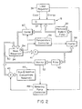
- Figure 2 is a schematic illustration of the dye handling portion of a dye laser system embodying the present invention.
- Figure 3 is an electrical schematic of the solute concentration monitor and metering pump controller of Figure 2.
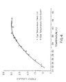
- Figure 4 is a plot of laser energy output relative to solution temperature for a given dye solution.
- Figure 5 is a plot of laser output wavelength against temperature for a given dye solution when a color regulator is not used.
- Figure 6 is a schematic illustration of an alternative embodiment of the dye circulation portion of a dye laser system of the present invention.
- FIG. 1 is an optical schematic of a laser system embodying the present invention.
- the laser cavity is a dye cell 20 through which a dye solution flows from an input 22 to an output 24.
- the dye solution is typically energized by a flash of light from a flashlamp (not shown) which causes the dye in the solution to lase.
- Light emitted from the back end of the dye cell is reflected back into the cell by a reflector 26; whereas, light emitted from the front end of the dye cell is only partially reflected by a reflector 28.
- Light not reflected by reflector 28 is the laser beam output from the system.
- a preferred application of the present invention is in a photothermolysis system. In that system the laser output is coupled through an optical coupler 30 to an optical fiber 32 through which it is directed to a hand held wand 34 for treatment of a patient's skin.
- a color regulator 36 is interposed between the dye cell 20 and the reflector 28.
- Typical intercavity laser tuners that can be used are interference filters, etalons, prisms, birefringent filters and gratings. Such regulators are typically found in systems to tune the color of the laser output and thus maintain a preset color despite changes in the dye solution. With the present invention, the requirement for such fine tuning is minimal, so the output at the preset wavelength can be maximized.
- the color at which the laser output is most efficient is set principally by the dyes used in the dye solution, or by the ratio of two or more dyes in the solution if multiple dye solutes are used.
- the concentrations of the dyes are also established to establish energy output of the laser.
- the dye solution includes one or more additives such as triplet quenchers, e.g. cyclooctatetraene (COT), and solubilizers.
- COT cyclooctatetraene
- solubilizers assist in keeping high concentrations of solute in solution and may include dimethyl formamide, propanol carbonate, methanol, ethanol or isopropanol.
- the solutes in the solution may degrade.
- COT which was included to quench the triplet state of the dye in long pulse lasers such as those used in photothermolysis.
- COT degrades rapidly into by-products which must then be removed from the solution to avoid degradation of the laser output, and the COT must be replenished.
- the filter employed typically a charcoal bed filter, not only removes the COT by-products but also other solutes such as dye. Accordingly, to maintain proper operation of the laser over cycles in the order of tens of thousands, the dye must be replenished as well.
- Another means to increase the useful life of the laser dye solutions is by maintaining these solutions at a proper pH value. This value can be determined empirically by ascertaining the number of laser pulses of useful quality that can be produced from a given quantity of laser dye in solution at a predetermined pH.
- the pH of the dye solution can be established and maintained by adding a suitable acid or base to the solution but, preferably, the pH is established and maintained by adding one or more pH buffer materials to the solution.
- Suitable buffers can be either organic or inorganic in nature. Examples of organic buffers include TRIS, MES and TES (Good's buffers). Examples of inorganic buffers include sodium phosphate, potassium phosphate and sodium bicarbonate. Mixtures of these buffer materials can be used if desired. The optimum pH will depend on the choice of solvent and solutes used. Once the optimum pH is determined, it can be maintained with the chosen buffers.
- the pH is maintained at a neutral to somewhat basic pH value, i.e. between pH 7.0 and pH 8.0.
- a particularly preferred pH value is pH 7.6 for the rhodamine dye laser solutions. This pH value can be adequately maintained with a mixture of K 2 HPO 4 and Na 2 HPO 4 .
- FIG. 2 illustrates a dye circulation system embodying the present invention for assuring uniform color and energy output from the dye laser with multiple pulses of the laser.
- a dye solution is pumped from a main reservoir 34 by a main pump 36 through a particle and bubble filter 38 and the dye cell 20 of laser 18.
- the laser is controlled by regulator 39 which controls color tuning through the optical color regulator 37 and laser excitation energy.
- a filter 40 such as a charcoal bed filter is provided in a filter loop for filtering out degraded solute and by-products of the laser operation.
- metering pump 42 delivers dye and additive concentrate from reservoir 46 into the filter bypass loop 50.
- Loop 50 returns the filtered and replenished dye solution to the main reservoir 34.
- a solute concentration monitor 52 is provided. That concentration monitor may take a number of forms, including optical or electrical sensors, but is preferably an optical monitor which senses light absorption at a wavelength corresponding to a signature of the dye solute or solutes as discussed below.
- a metering pump controller 48 controls the pump 42 in response to the monitored dye concentration. Although illustrated as being in a separate bypass loop, the filter and metering pump may be coupled into the main laser loop.
- the filter 40 is required principally to filter out the by-products of the lasing process such as by-products of COT degeneration. Unfortunately, the filter also removes still effective dye solute. In the past, the filter has been allowed to load with dye during operation of the laser until it approaches a balanced state with the circulating solution wherein only small amounts of dye are removed by the filter. Thereafter the filter continues to be effective in removing the undesirable by-products.
- the filter 40 is preloaded by circulating the dye solution through the filter for a period of time prior to firing of the laser.
- the filter may be preloaded at the factory to minimize the required size of the reservoir 46, or it may be preloaded from the reservoir 46 by cycling dye solution through the system while adding solute. In this way, with firing of the laser, the system does not first go through a period in which a large amount of dye is removed by the filter followed by a period during which only small amounts of dye are removed. With this system, small amounts of dye are consistently removed by the filter 40 and can be readily replenished with small amounts of dye concentrate delivered through the metering pump 42.
- pump 36 pumps at about four gallons per minute. One fourth of the flow is to the laser cell while three fourths of the flow is through the filter 40.
- the dye concentrate in reservoir 46 would be 0.5 mole of dye in 100 liters of solvent, and the additive concentrate would be 0.3 mole of COT in 10 3 liters of solvent. Since close control of dye concentration is much more critical than that of COT, the preferred system only monitors dye concentration and meters both dye solute and COT in response to the dye concentration.
- separate reservoirs and meter pumps may be provided for the dye and additive. In such a system, the dye and additive may be separately monitored for more precise metering of each.
- a preferred example of a PBF repository is a carbon bed filter, particularly a charcoal bed filter.
- the large surface area of activated charcoal and numerous pores allow dye and additive molecules to remain in residence within its structure.
- the solvent too is held within this structure and a solute-solvent balance is obtained with the solution.
- Other filters which may serve the purpose include vycor glass, alumina, silica gel, zeolite, and molecular absorption filters.
- a PBF repository system is included in a circulation system of a dye laser, the volume of solution can be reduced dramatically because the PBF repository can keep enormous amounts of dye and additives and still maintain the solution concentration at a useful level.
- the charcoal bed filter has another great advantage in that it can remove degradation products that lower the efficiency of the dye laser.
- the solution may contain one or more dyes, one or more additives, solubilizers and one or more solvents.
- the formulation will depend on the concentration of each species and therefore, the combination, can be infinite. The color and energy level outputs of such systems change over multiple laser pulses and are also temperature dependent.
- the surface area of a carbon or charcoal bed filter can be as much as 1,000 square meters per gram of carbon.
- Each has a different activation energy in the porous bed filter.
- the partition function at the solid-liquid interface is extremely complex. Moreover, the access to the inner pores is slow and transport limited by diffusion. Equilibrium is reached asymptotically and experiments show that equilibrium by diffusion may take days or weeks to be reached. Temperature, however, strongly affects the partition function and temperature effects overshadow diffusion processes.
- Figure 4 shows how the energy output of a dye laser containing a PBF repository changes as a function of temperature for a selected filter and solvent, dye solute and additive combination.
- the maximum laser output should not be considered as absolutely corresponding to a temperature of 40°C and higher.
- Another PBF repository with a different solvent, solute and/or additive may give maximum laser output at another temperature.
- the curve is similar to a curve used to optimize the output of a dye laser by varying the concentration(s) in a standard circulation system.
- the change in temperature changes the concentration of dye solute and additive in solution.
- the concentration at 40°C is such that there is a maximum output. As the temperature is raised, more dye solute and additives are driven out of the reservoir and into the solution.
- Figure 5 shows the color change of the dye laser containing the PBF repository described above.
- the color change again is not the direct result of a change in temperature, but more likely is due to the change in solute concentration.
- the dye solute, additive and solvent combination must be adjusted to give maximum output at the correct color at a chosen operating temperature. With experience, the choice from an infinite number of combinations can be reduced to a few combinations that are optimum or near optimum.
- the combination is only energy output optimum at some chosen temperature, and the color is such a strong function of temperature that it is important to thermostat the operating temperature.
- it is important to keep the color variation to within ⁇ 2 nm and since the slope of the color versus temperature curve is linear at 0.8 nm/C, it is important that the system be controlled at ⁇ 2.5 C.
- the circulation system further includes a temperature sensor 54, preferably located in the main reservoir 34.
- a temperature controller 56 responds to the sensed temperature to control a heater 58 and/or liquid cooling heat exchanger 60 in the main circulation loop.
- thermometers can be obtained by one of many available thermostats based on thermocouples, thermistors, liquid thermometers, and gas expansion bulbs.
- a good, accurate and nearly absolute thermometer can be derived using an integrated circuit temperature transducer such as AD592 by Analog Devices. They are convenient because in addition to having good sensitivity and range with a temperature coefficient in the order of microvolts/K, the output voltage is an absolute function of temperature, and therefore a comparison temperature calibration feature is not needed.
- cooling systems have been used to counter the heating caused by the laser firing process, and such cooling heat exchangers have typically kept the dye solution at about room temperature. It has been determined, however, that so long as the dye solution has been properly specified for operation at higher temperatures, the actual temperature to which the solution is held is not critical. Thus, to minimize cooling required by the system, the present system preferably runs at about 38-40°C. To maintain consistent color output, that temperature is maintained within 2.5°C and preferably within ⁇ 1°C. This higher temperature also provides the added advantage of requiring less dye in the system since at higher temperatures the filter removes less dye.
- the concentration of specific solutes is monitored at 52 by means of optical absorption at a specific wavelength.
- the solution being monitored is allowed to flow through a sensing cell 62.
- the solution is illuminated from one side by a pulsed source 64 of white light.
- An optical interference filter 66 on the opposite side of the sensing cell selects a specific, narrow range of wavelengths, with the center wavelength of the filter corresponding to a signature of the solute or solutes to be monitored.
- a photodiode 68 detects the light transmitted through the filter, and produces an electronic signal proportional to the amount of light reaching the photodiode.
- a second, "reference” photodiode 70 also views the light source 64 through an identical optical interference filter 72, but without the intervening solvent.
- the sensitivity of the two detection channels are adjusted so that they yield the same electronic signal strengths when the concentration of the solute in solution is optimum for operation of the laser. As the concentration of the specific solute of interest decreases below the optimum value, the solution absorbs progressively less light at the selected wavelength, and the signal strength produced by the sample photodiode therefore increases relative to that of the reference photodiode.
- the metering pump controller electronically subtracts the sample channel signal from the reference channel signal at comparator 74 producing a difference signal which increases in amplitude as the solute concentration decreases.
- the difference signal is used to control the injection of new solute in order to bring the solution back to optimum.
- New solute is injected in the form of a highly concentrated solution ("concentrate"), by means of an electrically actuated metering pump 42.
- Concentrate a highly concentrated solution
- Each actuation of the pump results in the injection of a known volume of concentrate into the laser dye solution.
- the number of pump actuations is derived directly from the difference signal by digitizing it in analog to digital converter 76 and loading the result into a counter 78 which in turn determines the number of metering pump actuations. In this way, the correct amount of concentrate is added each time the metering pump controller is operated.
- the metering pump controller operates at discrete intervals. At the start of the operating sequence, the metering pump controller causes the light source in the solute concentration monitor to pulse. The metering pump controller then detects the resulting electrical signal from the reference photodiode 70. The controller digitizes the difference signal (reference minus sample), loads the result into the electronic counter 78, and actuates the metering pump 42 based on the counter contents. The sequence repeats periodically, based on the accumulated number of laser pulses since the last sequence. The number of pulses which elapse between operations may be adjusted thus allowing the system to be tailored to the specific requirements of any particular dye laser.
- a long pulse dye laser with a dye circulation system as configured in Figure 6 was tested with two dye formulations.
- the structural features in Figure 6 are the same as those in Figure 2 and therefore retain the same designation numbers.
- the dye concentrate is metered into the system before the filter to provide more stable control of the concentration through the laser.
- the temperature control system would also be included in the most preferred embodiment.
- Rhodamine 560 4.4 gms Rhodamine 590 5.76 gms Ethylene Glycol 3.2 liters H 2 O 3.2 liters Cyclooctatetraene 9 ml K 2 HPO 4 7.6 gm Na 2 HPO 4 28 gm Activated Carbon Filter 3" dia x 10" Fluid Solutions C231 pH 7.6
- the other dye formulation was identical to the immediately preceding one with the exception that the K 2 HPO 4 and Na 2 HPO 4 substances were not present.
- the pH of this formulation was 3.5.
- the Rhodamine dyes were supplied by Exciton Chemical Corporation. Each alone lases at a wavelength of 560 and 590 nanometers, respectively, but the combination lases at about 585 nanometers.
- the dye concentration monitor was set to inject concentrate below absorbance of 0.4 at 530 nm.
- the dye concentrate was a solution with 0.015 molar R560 and 0.02 molar R590 in ethylene glycol.
- the laser output was fixed at 2.5 J and a feedback system increased the voltage on the capacitor bank to maintain constant output as the dye solution degraded.
- the voltage range was 4 KV to 6 KV. When the voltage reached 6 KV as the dye solution degraded, the system shut down and a warning was given.
Landscapes
- Physics & Mathematics (AREA)
- Electromagnetism (AREA)
- Engineering & Computer Science (AREA)
- Plasma & Fusion (AREA)
- Optics & Photonics (AREA)
- Lasers (AREA)
Description
| Rhodamine 560 | 4.4 |
| Rhodamine | |
| 590 | 5.76 gms |
| Ethylene Glycol | 3.2 liters |
| H2O | 3.2 liters |
| Cyclooctatetraene | 9 ml |
| K2HPO4 | 7.6 gm |
| Na2HPO4 | 28 gm |
| Activated Carbon Filter | 3" dia x 10" Fluid Solutions C231 |
| pH | 7.6 |
| pH of Solution | No. of Laser Pulses at 1 Hz Before System Shut Down |
| 3.5 | 3,000 - 5,000 |
| 7.6 | greater than 100,000 |
Claims (24)
- A dye laser system comprising:characterized by:a dye laser cell (20); anda porous bed filter (40) loaded prior to operation of the laser with solute such that dye solution at a predetermined operating dye solute concentration flowing into the porous bed filter remains at substantially the same dye solute concentration;a monitor (52) for monitoring dye solute concentration in the dye solution; anda solute supply (46) for replenishing dye solute and an additive solute in the dye solution in response to the monitored dye solute concentration.
- A system as claimed in Claim 1 further comprising:said monitor (52) comprising at least one filter having a passband at a characteristic wavelength of the dye solution and rejecting broadband fluorescence of the dye solution for monitoring absorption of the dye solution at the characteristic wavelength; andwherein said solute supply (46) automatically replenishes solute in the dye solution in response to monitored absorption.
- A system as claimed in either of Claims 1 or 2 further comprising an optical color regulator (37) for maintaining the color of the laser output.
- A system as claimed in any preceding Claim wherein the additive solute is cyclooctatetraene.
- A system as claimed in any preceding Claim further comprising a dye solution temperature controller.
- A system as claimed in any preceding Claim wherein the porous bed filter (40) comprises a carbon bed filter.
- A system as claimed in any preceding Claim wherein the monitor (52) monitors dye concentration and the solute supply (46) supplies dye solute and cyclooctatetraene solute in response to the dye solute monitor.
- A system as claimed in any preceding Claim wherein the pH of the solution is maintained at a preselected pH value.
- A system as claimed in Claim 8 wherein the preselected pH value is maintained with a buffer or buffer mixture.
- A system as claimed in any preceding Claim wherein the dye solute is at least one rhodamine dye.
- A system as claimed in Claim 10 wherein the dye solute is a mixture of rhodamine 560 and rhodamine 590.
- A method of replenishing a dye solution in a dye laser system comprising:characterised by:prior to operation of the dye laser (18), loading a porous bed filter (40) repository with solute such that dye solution at a predetermined operating dye solute concentration flowing into the porous bed filter (40) repository remains at substantially the same dye solute concentration;monitoring dye concentration in the dye solution by means of a monitor (52) in the dye laser system; andreplenishing dye solute and an additive solute in the dye solution in response to the monitored dye concentration.
- A method as claimed in claim 12 further comprising monitoring and controlling temperature of the dye solution.
- A method as claimed in claim 13 wherein the temperature is controlled to within ±2.5° centigrade.
- A method as claimed in any of claims 12 to 14 wherein the pH of the solution is maintained at a preselected pH value.
- A method as claimed in any of claims 12 to 15 further comprising optically regulating color output from the laser (18) to vary the color output.
- A method as claimed in any of claims 12 to 16 wherein the additive solute includes a triplet quencher.
- A method as claimed in any of claims 12 to 17 wherein the monitoring step is performed by monitoring optical absorption of the dye solution.
- A method as claimed in any of claims 12 to 18 wherein the porous bed filter (40) comprises a carbon bed filter.
- A method as claimed in any of claims 12 to 19 wherein both dye and a triplet quencher cyclooctatetraene are replenished in response to the monitored dye concentration.
- A method as claimed in any of claims 12 to 20 wherein the pH of the solution is maintained at a preselected pH value.
- A method as claimed in claim 21 wherein the preselected pH value is maintained with a buffer or buffer mixture.
- A method as claimed in any of claims 12 to 22 wherein the dye solute is at least one rhodamine dye.
- A method as claimed in claim 23 wherein the dye solute is a mixture of rhodamine 560 and rhodamine 590.
Applications Claiming Priority (5)
| Application Number | Priority Date | Filing Date | Title |
|---|---|---|---|
| US9846793A | 1993-07-28 | 1993-07-28 | |
| US98467 | 1993-07-28 | ||
| US08/165,331 US5668824A (en) | 1993-07-28 | 1993-12-10 | Method and apparatus for replenishing dye solution in a dye laser |
| US165331 | 1993-12-10 | ||
| PCT/US1994/008660 WO1995004393A2 (en) | 1993-07-28 | 1994-07-27 | Apparatus and method for replenishing laser dye solution |
Publications (2)
| Publication Number | Publication Date |
|---|---|
| EP0711463A1 EP0711463A1 (en) | 1996-05-15 |
| EP0711463B1 true EP0711463B1 (en) | 1999-10-06 |
Family
ID=26794773
Family Applications (1)
| Application Number | Title | Priority Date | Filing Date |
|---|---|---|---|
| EP94924534A Expired - Lifetime EP0711463B1 (en) | 1993-07-28 | 1994-07-27 | Apparatus and method for replenishing laser dye solution |
Country Status (8)
| Country | Link |
|---|---|
| US (3) | US5668824A (en) |
| EP (1) | EP0711463B1 (en) |
| JP (1) | JP3667755B2 (en) |
| KR (1) | KR100343271B1 (en) |
| AU (1) | AU7478094A (en) |
| CA (1) | CA2168237C (en) |
| DE (1) | DE69421081T2 (en) |
| WO (1) | WO1995004393A2 (en) |
Families Citing this family (20)
| Publication number | Priority date | Publication date | Assignee | Title |
|---|---|---|---|---|
| US5668824A (en) * | 1993-07-28 | 1997-09-16 | Cynosure, Inc. | Method and apparatus for replenishing dye solution in a dye laser |
| US5624435A (en) * | 1995-06-05 | 1997-04-29 | Cynosure, Inc. | Ultra-long flashlamp-excited pulse dye laser for therapy and method therefor |
| US6077294A (en) | 1998-06-11 | 2000-06-20 | Cynosure, Inc. | Method for non-invasive wrinkle removal and skin treatment |
| US6506505B1 (en) * | 1999-08-16 | 2003-01-14 | The University Of Southern California | Cyclooctatetraenes as electron transporters in organic light emitting diodes |
| US6554825B1 (en) | 2000-05-09 | 2003-04-29 | Laserscope | Variable pulse duration, adjustable wavelength medical laser system |
| WO2003047052A2 (en) * | 2001-11-21 | 2003-06-05 | General Atomics | Laser containing a distributed gain medium |
| US6765941B2 (en) * | 2001-12-03 | 2004-07-20 | Agfa Corporation | Method and apparatus for cooling a self-contained laser head |
| KR20050026404A (en) | 2002-06-19 | 2005-03-15 | 팔로마 메디칼 테크놀로지스, 인코포레이티드 | Method and apparatus for photothermal treatment of tissue at depth |
| US20040264519A1 (en) * | 2003-06-24 | 2004-12-30 | Morrell John Alan | Filter bypass method and system for chiller loop to control purity levels |
| US7242701B2 (en) * | 2005-02-15 | 2007-07-10 | Lucent Technologies Inc. | Laser wavelength control arrangement and method |
| US7856985B2 (en) | 2005-04-22 | 2010-12-28 | Cynosure, Inc. | Method of treatment body tissue using a non-uniform laser beam |
| US7586957B2 (en) | 2006-08-02 | 2009-09-08 | Cynosure, Inc | Picosecond laser apparatus and methods for its operation and use |
| US7792175B2 (en) | 2007-03-27 | 2010-09-07 | Bernstein Eric F | Triplet quencher for use in lasers |
| GB2468727B (en) * | 2009-03-20 | 2014-05-14 | Thales Holdings Uk Plc | Fluid handling for laser based weapons systems |
| KR102342629B1 (en) | 2012-04-18 | 2021-12-22 | 싸이노슈어, 엘엘씨 | Picosecond laser apparatus and methods for treating target tissues with same |
| US8837550B2 (en) | 2012-11-08 | 2014-09-16 | Massachusetts Institute Of Technology | Continuous-wave organic dye lasers and methods |
| WO2014145707A2 (en) | 2013-03-15 | 2014-09-18 | Cynosure, Inc. | Picosecond optical radiation systems and methods of use |
| US9957336B2 (en) * | 2014-05-08 | 2018-05-01 | The United States Of America As Represented By The Administrator Of Nasa | Method of making dye-doped polystyre microparticles |
| CN104064957B (en) * | 2014-05-09 | 2017-04-05 | 杭州电子科技大学 | A kind of controllable optofluidic dye laser based on electric rheological effect |
| CN112042066A (en) | 2018-02-26 | 2020-12-04 | 赛诺秀股份有限公司 | Q-switched cavity-tilting subnanosecond laser |
Family Cites Families (15)
| Publication number | Priority date | Publication date | Assignee | Title |
|---|---|---|---|---|
| US4139342A (en) * | 1977-07-18 | 1979-02-13 | Hughes Aircraft Company | Dye impregnated plastics for laser applications |
| DE2923583A1 (en) * | 1979-06-11 | 1980-12-18 | Max Planck Gesellschaft | METHOD FOR THE IMMUNOLOGICAL DETERMINATION OF BASAL MEMBRANE MATERIAL AND NEW BASAL MEMBRANE FRAGMENTS SUITABLE FOR THIS |
| US4364015A (en) * | 1981-03-12 | 1982-12-14 | Jersey Nuclear-Avco Isotopes, Inc. | Compact reservoir system for dye lasers |
| US4445217A (en) * | 1981-11-09 | 1984-04-24 | International Laser Systems, Inc. | Laser apparatus and method |
| US4977571A (en) * | 1988-03-29 | 1990-12-11 | Candela Laser Corporation | Dye laser solution circulation system |
| US4891817A (en) * | 1988-06-13 | 1990-01-02 | Eastman Kodak Company | Pulsed dye laser apparatus for high PRF operation |
| JPH022199A (en) * | 1988-06-14 | 1990-01-08 | Toshiba Corp | Dye circulator of dye laser |
| US4878224A (en) * | 1988-09-16 | 1989-10-31 | Hoechst Celanese Corporation | Dye lasers |
| JPH0285694A (en) * | 1988-09-20 | 1990-03-27 | Nippon Sanso Kk | Plate-fin type heat exchanger |
| US4896329A (en) * | 1989-06-01 | 1990-01-23 | Exciton Incorporated | Laser dye liquids, laser dye instruments and methods |
| JPH0319385A (en) * | 1989-06-16 | 1991-01-28 | Mitsubishi Electric Corp | Dye laser device |
| FR2650196B1 (en) * | 1989-07-06 | 1991-12-06 | Technomed Internat | METHOD AND APPARATUS FOR REGENERATING A DYE SOLUTION IN A DILUENT, IN PARTICULAR A DYE SOLUTION FOR A DYE LASER |
| JPH03183184A (en) * | 1989-12-13 | 1991-08-09 | Toshiba Corp | Monitor for dye deterioration of ring dye laser oscillator |
| US5109387A (en) * | 1990-12-26 | 1992-04-28 | Garden Jerome M | Dye laser system and method |
| US5668824A (en) * | 1993-07-28 | 1997-09-16 | Cynosure, Inc. | Method and apparatus for replenishing dye solution in a dye laser |
-
1993
- 1993-12-10 US US08/165,331 patent/US5668824A/en not_active Expired - Lifetime
-
1994
- 1994-07-27 JP JP50603895A patent/JP3667755B2/en not_active Expired - Fee Related
- 1994-07-27 EP EP94924534A patent/EP0711463B1/en not_active Expired - Lifetime
- 1994-07-27 WO PCT/US1994/008660 patent/WO1995004393A2/en not_active Ceased
- 1994-07-27 DE DE69421081T patent/DE69421081T2/en not_active Expired - Fee Related
- 1994-07-27 CA CA002168237A patent/CA2168237C/en not_active Expired - Fee Related
- 1994-07-27 AU AU74780/94A patent/AU7478094A/en not_active Abandoned
- 1994-07-27 KR KR1019960700454A patent/KR100343271B1/en not_active Expired - Fee Related
-
1997
- 1997-09-15 US US08/929,883 patent/US6246710B1/en not_active Expired - Lifetime
-
2001
- 2001-06-08 US US09/877,500 patent/US6570900B2/en not_active Expired - Fee Related
Non-Patent Citations (2)
| Title |
|---|
| "Instruction Manual TFDL-10, Adapted for SLAC", CANDELA CORPORATION, NATICK,MA, US, OCT.85 * |
| "Special Instructions and Test Results for the LFDL-2 Wave Guide Laser", CANDELA CORPORATION, NATICK, MASSACHUSETTS, US, SEPT. 82 * |
Also Published As
| Publication number | Publication date |
|---|---|
| WO1995004393A2 (en) | 1995-02-09 |
| US5668824A (en) | 1997-09-16 |
| DE69421081T2 (en) | 2000-05-25 |
| US20010043635A1 (en) | 2001-11-22 |
| US6570900B2 (en) | 2003-05-27 |
| CA2168237A1 (en) | 1995-02-09 |
| CA2168237C (en) | 2005-05-10 |
| DE69421081D1 (en) | 1999-11-11 |
| KR100343271B1 (en) | 2002-11-30 |
| JPH09501799A (en) | 1997-02-18 |
| AU7478094A (en) | 1995-02-28 |
| JP3667755B2 (en) | 2005-07-06 |
| US6246710B1 (en) | 2001-06-12 |
| WO1995004393A3 (en) | 1995-03-16 |
| EP0711463A1 (en) | 1996-05-15 |
Similar Documents
| Publication | Publication Date | Title |
|---|---|---|
| US5668824A (en) | Method and apparatus for replenishing dye solution in a dye laser | |
| US6157662A (en) | F2 (157nm) laser employing neon as the buffer gas | |
| EP0564569B1 (en) | Dye laser system and method | |
| Bedö et al. | Saturation of the 2.71 μm laser output in erbium-doped ZBLAN fibers | |
| Weiss | Pump saturation in molecular far-infrared lasers | |
| US5926495A (en) | Laser diode pump wavelength sensing and control apparatus and method | |
| US6292498B1 (en) | Method of controlling diode-laser wavelength in a diode-laser pumped solid-state laser | |
| US5974062A (en) | Laser drive method, laser drive system, and radiation image read-out apparatus | |
| Rabien et al. | Test performance of the parsec laser system | |
| US4603422A (en) | Long-lived laser dye | |
| US4238741A (en) | Technique for generating 14 and 16 micron CO2 laser radiation | |
| Wellegehausen et al. | Cascade laser emission of optically pumped Na2 molecules | |
| Morris et al. | Is a cw 3 μm holmium laser possible? A spectroscopic study | |
| Littler et al. | Molecular beam Raman laser with a 250 nW threshold pump power | |
| JPH06204623A (en) | Dye solution circulating device | |
| SU1455374A1 (en) | Gas laser | |
| Diemer et al. | Infrared atomic Cs laser based on optical pumping of Cs2 molecules | |
| Calkins et al. | A dye laser source of monochromatic UV‐B and UV‐C radiations for biological action spectroscopy | |
| Courtois et al. | Frequency and amplitude stabilization device for a cw CO2 laser | |
| Stephens et al. | Potential for a chemically pumped sodium laser | |
| Wheeler et al. | Dyes and dye mixtures useful for generation of UV in a flashlamp driven tunable dye laser | |
| EP1775805A1 (en) | Frequency Stabilised Gaslaser | |
| Liang et al. | Polarization and power characteristics of pulsed dye lasers with transverse pumping | |
| Gassen et al. | A high power dye laser pumped by a crowbar mode flashlamp | |
| JP2004515903A (en) | Energy stabilized gas discharge laser |
Legal Events
| Date | Code | Title | Description |
|---|---|---|---|
| PUAI | Public reference made under article 153(3) epc to a published international application that has entered the european phase |
Free format text: ORIGINAL CODE: 0009012 |
|
| 17P | Request for examination filed |
Effective date: 19960201 |
|
| AK | Designated contracting states |
Kind code of ref document: A1 Designated state(s): DE FR GB IT |
|
| 17Q | First examination report despatched |
Effective date: 19960603 |
|
| RAP1 | Party data changed (applicant data changed or rights of an application transferred) |
Owner name: CYNOSURE, INC. |
|
| GRAG | Despatch of communication of intention to grant |
Free format text: ORIGINAL CODE: EPIDOS AGRA |
|
| GRAG | Despatch of communication of intention to grant |
Free format text: ORIGINAL CODE: EPIDOS AGRA |
|
| GRAG | Despatch of communication of intention to grant |
Free format text: ORIGINAL CODE: EPIDOS AGRA |
|
| GRAH | Despatch of communication of intention to grant a patent |
Free format text: ORIGINAL CODE: EPIDOS IGRA |
|
| GRAH | Despatch of communication of intention to grant a patent |
Free format text: ORIGINAL CODE: EPIDOS IGRA |
|
| GRAA | (expected) grant |
Free format text: ORIGINAL CODE: 0009210 |
|
| AK | Designated contracting states |
Kind code of ref document: B1 Designated state(s): DE FR GB IT |
|
| REF | Corresponds to: |
Ref document number: 69421081 Country of ref document: DE Date of ref document: 19991111 |
|
| ITF | It: translation for a ep patent filed | ||
| ET | Fr: translation filed | ||
| PLBE | No opposition filed within time limit |
Free format text: ORIGINAL CODE: 0009261 |
|
| STAA | Information on the status of an ep patent application or granted ep patent |
Free format text: STATUS: NO OPPOSITION FILED WITHIN TIME LIMIT |
|
| 26N | No opposition filed | ||
| REG | Reference to a national code |
Ref country code: GB Ref legal event code: IF02 |
|
| PGFP | Annual fee paid to national office [announced via postgrant information from national office to epo] |
Ref country code: FR Payment date: 20090727 Year of fee payment: 16 |
|
| PGFP | Annual fee paid to national office [announced via postgrant information from national office to epo] |
Ref country code: GB Payment date: 20090730 Year of fee payment: 16 Ref country code: DE Payment date: 20090811 Year of fee payment: 16 |
|
| PGFP | Annual fee paid to national office [announced via postgrant information from national office to epo] |
Ref country code: IT Payment date: 20090731 Year of fee payment: 16 |
|
| GBPC | Gb: european patent ceased through non-payment of renewal fee |
Effective date: 20100727 |
|
| REG | Reference to a national code |
Ref country code: FR Ref legal event code: ST Effective date: 20110331 |
|
| PG25 | Lapsed in a contracting state [announced via postgrant information from national office to epo] |
Ref country code: DE Free format text: LAPSE BECAUSE OF NON-PAYMENT OF DUE FEES Effective date: 20110201 |
|
| REG | Reference to a national code |
Ref country code: DE Ref legal event code: R119 Ref document number: 69421081 Country of ref document: DE Effective date: 20110201 |
|
| PG25 | Lapsed in a contracting state [announced via postgrant information from national office to epo] |
Ref country code: IT Free format text: LAPSE BECAUSE OF NON-PAYMENT OF DUE FEES Effective date: 20100727 Ref country code: FR Free format text: LAPSE BECAUSE OF NON-PAYMENT OF DUE FEES Effective date: 20100802 |
|
| PG25 | Lapsed in a contracting state [announced via postgrant information from national office to epo] |
Ref country code: GB Free format text: LAPSE BECAUSE OF NON-PAYMENT OF DUE FEES Effective date: 20100727 |