EP0711398B1 - Heat exchanger for fitting in a tank which forms part of a vehicle radiator - Google Patents
Heat exchanger for fitting in a tank which forms part of a vehicle radiator Download PDFInfo
- Publication number
- EP0711398B1 EP0711398B1 EP95923230A EP95923230A EP0711398B1 EP 0711398 B1 EP0711398 B1 EP 0711398B1 EP 95923230 A EP95923230 A EP 95923230A EP 95923230 A EP95923230 A EP 95923230A EP 0711398 B1 EP0711398 B1 EP 0711398B1
- Authority
- EP
- European Patent Office
- Prior art keywords
- plate
- plates
- slots
- heat exchanger
- pair
- Prior art date
- Legal status (The legal status is an assumption and is not a legal conclusion. Google has not performed a legal analysis and makes no representation as to the accuracy of the status listed.)
- Expired - Lifetime
Links
- 210000002105 tongue Anatomy 0.000 claims description 23
- 239000012530 fluid Substances 0.000 claims description 6
- 238000004519 manufacturing process Methods 0.000 description 10
- 239000000463 material Substances 0.000 description 3
- 210000002445 nipple Anatomy 0.000 description 2
- 239000002826 coolant Substances 0.000 description 1
Images
Classifications
-
- F—MECHANICAL ENGINEERING; LIGHTING; HEATING; WEAPONS; BLASTING
- F28—HEAT EXCHANGE IN GENERAL
- F28D—HEAT-EXCHANGE APPARATUS, NOT PROVIDED FOR IN ANOTHER SUBCLASS, IN WHICH THE HEAT-EXCHANGE MEDIA DO NOT COME INTO DIRECT CONTACT
- F28D1/00—Heat-exchange apparatus having stationary conduit assemblies for one heat-exchange medium only, the media being in contact with different sides of the conduit wall, in which the other heat-exchange medium is a large body of fluid, e.g. domestic or motor car radiators
- F28D1/02—Heat-exchange apparatus having stationary conduit assemblies for one heat-exchange medium only, the media being in contact with different sides of the conduit wall, in which the other heat-exchange medium is a large body of fluid, e.g. domestic or motor car radiators with heat-exchange conduits immersed in the body of fluid
- F28D1/03—Heat-exchange apparatus having stationary conduit assemblies for one heat-exchange medium only, the media being in contact with different sides of the conduit wall, in which the other heat-exchange medium is a large body of fluid, e.g. domestic or motor car radiators with heat-exchange conduits immersed in the body of fluid with plate-like or laminated conduits
- F28D1/0308—Heat-exchange apparatus having stationary conduit assemblies for one heat-exchange medium only, the media being in contact with different sides of the conduit wall, in which the other heat-exchange medium is a large body of fluid, e.g. domestic or motor car radiators with heat-exchange conduits immersed in the body of fluid with plate-like or laminated conduits the conduits being formed by paired plates touching each other
- F28D1/0325—Heat-exchange apparatus having stationary conduit assemblies for one heat-exchange medium only, the media being in contact with different sides of the conduit wall, in which the other heat-exchange medium is a large body of fluid, e.g. domestic or motor car radiators with heat-exchange conduits immersed in the body of fluid with plate-like or laminated conduits the conduits being formed by paired plates touching each other the plates having lateral openings therein for circulation of the heat-exchange medium from one conduit to another
- F28D1/0333—Heat-exchange apparatus having stationary conduit assemblies for one heat-exchange medium only, the media being in contact with different sides of the conduit wall, in which the other heat-exchange medium is a large body of fluid, e.g. domestic or motor car radiators with heat-exchange conduits immersed in the body of fluid with plate-like or laminated conduits the conduits being formed by paired plates touching each other the plates having lateral openings therein for circulation of the heat-exchange medium from one conduit to another the plates having integrated connecting members
Definitions
- the present invention relates to a heat exchanger for fitting in a tank which forms part of a vehicle radiator, comprising a number of plate pairs stacked one on another, each pair consisting of a larger and a smaller elongate plate, which plates have all-round edge flanges which are bent towards one another and which, when the smaller plate is arranged in the larger, form a lap joint, surface-area enlargers being arranged both between the plates in each plate pair and between plate pairs lying adjacent to one another, and the plates being provided with holes at their ends for forming inlets and outlets respectively for the fluid which is to be cooled.
- Heat exchangers of the abovementioned type are described in SE 8605488-9.
- the holes are circular and project outwards to form cylindrical collars which seal the heat exchanger unit to the external surroundings. Introduced into the holes is an inlet nipple for the oil which is to be cooled.
- circulation difficulties arise for the oil between the nipple and the collars, for which reason it is desirable to move away from these collars.
- problems arise with the plate pairs sliding in relation to one another during the manufacturing process.
- a heat exchanger with another type of plate is described in WO 93/10415.
- the plates according to this document lack bent-up, all-round edge flanges, for which reason not only the plate pairs but also the plates within each pair slide in relation to one another during the manufacturing process. It is attempted to remedy this by means of two external pins on each plate which are at right angles to the plane of the plate and which are arranged in diametrically opposite "corners" and which face one another within a plate pair. These external pins prevent sliding of the plates within each pair in relation to one another.
- each plate is provided, at the hole at only one end, with three pins which are at right angles to the plane of the plate and which are arranged to engage with the hole at one end of an adjacent plate pair.
- All the plates in a heat exchanger of this type are the same, which means that the plates within each pair must be turned so that the internal pins of one plate end up at one end of the heat exchanger unit and the other plate must be turned so that its pins end up at the other end of the heat exchanger unit. Furthermore, the pairs must be turned in relation to one another so that those plates lying adjacent to one another of two plates have their pins arranged at different ends of the heat exchanger unit, otherwise the pins would bang into one another and it would not be possible to assemble the unit. Moreover, the plate pairs would be capable of sliding in relation to one another at the end where there are no pins. This renders more difficult and complicates manufacturing the heat exchanger since great attention has to be paid the whole time that all plates are turned in the right direction.
- One aim of the present invention is to produce a heat exchanger in which the plates do not slide in relation to one another during the manufacturing process without for this reason having to use a complicated manufacturing method.
- a heat exchanger for fitting in a tank which forms part of a vehicle radiator comprising a number of plate pairs stacked one on another, each pair consisting of a larger and a smaller elongate plate, which plates have all-round edge flanges which are bent towards one another and which, when the smaller plate is arranged in the larger, form a lap joint, surface-area enlargers being arranged both between the plates in each plate pair and between plate pairs lying adjacent to one another, and the plates being provided with holes at their ends for forming inlets and outlets respectively for the fluid which is to be cooled, characterized in that one plate of each pair is provided at each of its holes with at least two slots which extend from the hole parallel to the longitudinal axis of the plate, and in that the other plate of each pair is provided at each of its holes with at least two slots which extend from the hole parallel to the longitudinal axis of the plate, said other plate further having at least one tongue formed between the slots and bent out from the plate, to the side of the plate opposite
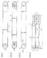
- Fig. 1 shows one of the larger plates seen from the side which faces inwards in the pair.
- Fig. 2 shows one of the smaller plates seen from the side which faces inwards in the pair.
- Fig. 3 shows a part of a heat exchanger unit seen from above with a large plate arranged at the top.
- Fig. 4 shows the same part of a heat exchanger unit which is shown in Fig. 3, sectioned according to the arrows IV-IV in Fig. 3.
- a heat exchanger for fitting in a tank which forms part of a vehicle radiator comprises a number of plate pairs 1 stacked one on another, each pair consisting of a larger and a smaller elongate plate 2, 3.
- the plates have all-round edge flanges 4 which are bent towards one another and which, when the smaller plate 3 is arranged in the larger, form a lap joint.
- Surface-area enlargers 5 are arranged both between the plates in each plate pair and between plate pairs lying adjacent to one another, as is shown diagrammatically in Fig. 4.
- the arrangement of surface-area enlargers in a heat exchanger is self-evident for the expert in the field, for which reason no further description of the surface-area enlargers will be given.
- the plates are provided with holes 6 at their ends for forming inlets and outlets respectively for the fluid which is to be cooled.
- the fluid which is to be cooled will flow inside the plate pairs and can progress from one plate pair to the next via the holes 6 in the plates.
- the cooling medium will flow outside and between the plate pairs.
- the upper of these plates has a hole at each end for forming an inlet and outlet respectively for the fluid which is to be cooled.
- the lower of these plates lacks holes and thus seals the heat exchanger to the surroundings.
- the plates 2, 3 cannot slide in relation to one another within a plate pair during the manufacturing process by virtue of the fact that the plates have all-round edge flanges 4 which are bent towards one another and which form a lap joint when the smaller plate 3 is arranged in the larger 2. These edge flanges can be seen best in Figs 1, 2 and 4.
- the larger plates 2 are provided with slots 7 and the smaller plates 3 are provided with tongues 8 which engage therein.
- the holes 6 are essentially D-shaped with the straight part facing the centre of the plate.
- the slots 7 in the larger plates 2 are arranged in the straight part of the holes 6.
- the smaller plates 3 are, in the straight part of each of their holes 6, provided with three slots 9 which extend from the hole parallel to the longitudinal axis of the plate and two tongues 8 formed between the slots.
- the tongues 8 at each hole namely the tongue 8a
- the slots 9 at each hole namely the slot 9a
- the tongues 8 also extend parallel to the longitudinal axis of the plate, and the tongue 8a is bent out from the plate on the opposite side of this in relation to the edge flange 4. In this embodiment, the tongue 8a is bent out at 45° in relation to the plate. Other bending-out angles are also possible in principle, at least in the range 30-90°.
- the slots 9 and the tongues 8 of the smaller plate 3 are, at both ends of the plate, offset from the central longitudinal axis of the plate towards one of its longitudinal sides so that the bent-out tongue 8a of a plate pair not only fits in the slots 7 in the larger plate 2 but also in the slot 9a in the smaller plate 3 of an adjacent plate pair.
- the plate pairs are stacked with a smaller plate 3 bearing against a larger plate 2 in the whole stack, except at one point where two smaller plates face one another.
- the tongue 8a and the slot 9a the two smaller plates cannot slide in relation to one another during the manufacturing process either.
- the larger plates are provided with only slots while the smaller plates are provided with both engagement tongues and slots. It is, however, possible to change around so that the larger plates are provided with both engagement tongues and slots and that the smaller are provided with only slots. Then, however, the size of the outermost plates made of heavier material must also be adapted to this.
- the larger plates also have two slots, and the smaller plates have two tongues and three slots.
- at least two slots are required in one plate and at least one tongue and at least one slot in the other.
- an extra slot is obtained moreover on the other side of the tongue.
Landscapes
- Engineering & Computer Science (AREA)
- Physics & Mathematics (AREA)
- Thermal Sciences (AREA)
- Mechanical Engineering (AREA)
- General Engineering & Computer Science (AREA)
- Heat-Exchange Devices With Radiators And Conduit Assemblies (AREA)
Description
Claims (4)
- Heat exchanger for fitting in a tank which forms part of a vehicle radiator, comprising a number of plate pairs (1) stacked one on another, each pair consisting of a larger (2) and a smaller (3) elongate plate, which plates have all-round edge flanges (4) which are bent towards one another and which, when the smaller plate (3) is arranged in the larger (2), form a lap joint, surface-area enlargers (5) being arranged both between the plates in each plate pair and between plate pairs lying adjacent to one another, and the plates being provided with holes (6) at their ends for forming inlets and outlets respectively for the fluid which is to be cooled, characterized in that one plate of each pair is provided at each of its holes (6) with at least two slots (7) which extend from the hole (6) parallel to the longitudinal axis of the plate, and in that the other plate of each pair is provided at each of its holes (6) with at least two slots (8a, 9a) which extend from the hole parallel to the longitudinal axis of the plate, said other plate further having at least one tongue (8a) formed between the slots and bent out from the plate, to the side of the plate opposite to the direction of the edge flange, which tongue (8a) engages in the at least one slot (7,9a) of an adjacent plate in an adjacent plate pair.
- Heat exchanger according to Claim 1, wherein the slots (7) of one plate are centred in relation to the central longitudinal axis of the plate and in that the tongues (8a) and the slots (9a) of the other plate are offset from the central longitudinal axis of the plate towards one of its longitudinal sides.
- Heat exchanger according to any one of the preceding claims, wherein the holes (6) are D-shaped with the straight part facing the centre of the plate (2, 3), the tongues (8a) and the slots (7, 9a) being arranged in the straight part.
- Heat exchanger according to any one of the preceding claims, wherein the tongues (8a) are bent out at 45° in relation to the plate.
Applications Claiming Priority (3)
| Application Number | Priority Date | Filing Date | Title |
|---|---|---|---|
| SE9401929A SE9401929L (en) | 1994-06-06 | 1994-06-06 | Heat exchanger for insertion into a tank contained in a vehicle cooler |
| SE9401929 | 1994-06-06 | ||
| PCT/EP1995/002134 WO1995033967A1 (en) | 1994-06-06 | 1995-06-06 | Heat exchanger for fitting in a tank which forms part of a vehicle radiator |
Publications (2)
| Publication Number | Publication Date |
|---|---|
| EP0711398A1 EP0711398A1 (en) | 1996-05-15 |
| EP0711398B1 true EP0711398B1 (en) | 1998-09-02 |
Family
ID=20394239
Family Applications (1)
| Application Number | Title | Priority Date | Filing Date |
|---|---|---|---|
| EP95923230A Expired - Lifetime EP0711398B1 (en) | 1994-06-06 | 1995-06-06 | Heat exchanger for fitting in a tank which forms part of a vehicle radiator |
Country Status (5)
| Country | Link |
|---|---|
| EP (1) | EP0711398B1 (en) |
| DE (1) | DE69504454T2 (en) |
| ES (1) | ES2122633T3 (en) |
| SE (1) | SE9401929L (en) |
| WO (1) | WO1995033967A1 (en) |
Families Citing this family (1)
| Publication number | Priority date | Publication date | Assignee | Title |
|---|---|---|---|---|
| PL328065A1 (en) * | 1996-02-01 | 1999-01-04 | Northern Res & Eng | Plate-and-ribs heat exchanger of unitary construction |
Family Cites Families (5)
| Publication number | Priority date | Publication date | Assignee | Title |
|---|---|---|---|---|
| FR481829A (en) * | 1916-01-20 | 1917-01-23 | Goudard & Mennesson M | Improvements made to temperature exchangers, such as, in particular, liquid circulation coolers for explosion engines |
| FR484353A (en) * | 1917-01-30 | 1917-10-02 | Goudard & Mennesson M | Improvements to radiators for explosion engines |
| CA1313183C (en) * | 1989-02-24 | 1993-01-26 | Allan K. So | Embossed plate heat exchanger |
| CA1313182C (en) * | 1989-02-24 | 1993-01-26 | Allan K. So | In tank oil cooler |
| CA2056678C (en) * | 1991-11-29 | 1995-10-31 | John G. Burgers | Full fin evaporator core |
-
1994
- 1994-06-06 SE SE9401929A patent/SE9401929L/en not_active IP Right Cessation
-
1995
- 1995-06-06 ES ES95923230T patent/ES2122633T3/en not_active Expired - Lifetime
- 1995-06-06 WO PCT/EP1995/002134 patent/WO1995033967A1/en not_active Ceased
- 1995-06-06 DE DE69504454T patent/DE69504454T2/en not_active Expired - Fee Related
- 1995-06-06 EP EP95923230A patent/EP0711398B1/en not_active Expired - Lifetime
Also Published As
| Publication number | Publication date |
|---|---|
| WO1995033967A1 (en) | 1995-12-14 |
| DE69504454D1 (en) | 1998-10-08 |
| DE69504454T2 (en) | 1999-01-14 |
| SE9401929D0 (en) | 1994-06-06 |
| EP0711398A1 (en) | 1996-05-15 |
| SE501952C2 (en) | 1995-06-26 |
| ES2122633T3 (en) | 1998-12-16 |
| SE9401929L (en) | 1995-06-26 |
Similar Documents
| Publication | Publication Date | Title |
|---|---|---|
| CN111316057B (en) | Multi-fluid heat exchanger | |
| US5088552A (en) | Method of constructing a heat exchanger and a heat exchanger constructed by using that method | |
| US6530425B2 (en) | Plate heat exchanger | |
| US5327958A (en) | Stacked-plate heat exchanger | |
| US5228515A (en) | Modular, compact heat exchanger | |
| GB2161913A (en) | Plate heat exchanger | |
| EP4103904B1 (en) | A heat exchanger plate, and a plate heat exchanger | |
| WO1993025860A1 (en) | Plate heat exchanger for liquids with different flows | |
| EP1282806A1 (en) | Plate pack, heat transfer plate and plate heat exchanger | |
| US6446712B1 (en) | Radial flow annular heat exchangers | |
| US4029145A (en) | Brazeless heat exchanger of the tube and shell type | |
| EP0088316B1 (en) | Plate heat exchanger | |
| JP4338480B2 (en) | Heat exchanger | |
| EP0984239B1 (en) | Heat exchanger | |
| EP1405023B1 (en) | Heat transfer plate, plate pack and plate heat exchanger | |
| EP0711398A1 (en) | Heat exchanger for fitting in a tank which forms part of a vehicle radiator | |
| AU755895B2 (en) | Radial flow annular heat exchangers | |
| JP2741950B2 (en) | Stacked heat exchanger | |
| US6374904B1 (en) | Heat exchanger and channel member therefor | |
| EP4474747A1 (en) | A heat exchanger | |
| CA3167538C (en) | A heat exchanger plate, and a plate heat exchanger | |
| JPH0518621Y2 (en) | ||
| JP2005016851A (en) | Heat exchanger | |
| JPH087266Y2 (en) | Stacked heat exchanger | |
| CA1312456C (en) | Method of constructing a heat exchanger and a heat exchanger constructed by using that method |
Legal Events
| Date | Code | Title | Description |
|---|---|---|---|
| PUAI | Public reference made under article 153(3) epc to a published international application that has entered the european phase |
Free format text: ORIGINAL CODE: 0009012 |
|
| 17P | Request for examination filed |
Effective date: 19960111 |
|
| AK | Designated contracting states |
Kind code of ref document: A1 Designated state(s): DE ES FR GB IT |
|
| 17Q | First examination report despatched |
Effective date: 19970411 |
|
| GRAG | Despatch of communication of intention to grant |
Free format text: ORIGINAL CODE: EPIDOS AGRA |
|
| GRAG | Despatch of communication of intention to grant |
Free format text: ORIGINAL CODE: EPIDOS AGRA |
|
| GRAH | Despatch of communication of intention to grant a patent |
Free format text: ORIGINAL CODE: EPIDOS IGRA |
|
| GRAH | Despatch of communication of intention to grant a patent |
Free format text: ORIGINAL CODE: EPIDOS IGRA |
|
| GRAA | (expected) grant |
Free format text: ORIGINAL CODE: 0009210 |
|
| ITF | It: translation for a ep patent filed | ||
| AK | Designated contracting states |
Kind code of ref document: B1 Designated state(s): DE ES FR GB IT |
|
| REF | Corresponds to: |
Ref document number: 69504454 Country of ref document: DE Date of ref document: 19981008 |
|
| REG | Reference to a national code |
Ref country code: ES Ref legal event code: FG2A Ref document number: 2122633 Country of ref document: ES Kind code of ref document: T3 |
|
| ET | Fr: translation filed | ||
| PG25 | Lapsed in a contracting state [announced via postgrant information from national office to epo] |
Ref country code: GB Free format text: LAPSE BECAUSE OF NON-PAYMENT OF DUE FEES Effective date: 19990606 |
|
| PG25 | Lapsed in a contracting state [announced via postgrant information from national office to epo] |
Ref country code: ES Free format text: LAPSE BECAUSE OF NON-PAYMENT OF DUE FEES Effective date: 19990607 |
|
| PLBE | No opposition filed within time limit |
Free format text: ORIGINAL CODE: 0009261 |
|
| STAA | Information on the status of an ep patent application or granted ep patent |
Free format text: STATUS: NO OPPOSITION FILED WITHIN TIME LIMIT |
|
| 26N | No opposition filed | ||
| GBPC | Gb: european patent ceased through non-payment of renewal fee |
Effective date: 19990606 |
|
| PG25 | Lapsed in a contracting state [announced via postgrant information from national office to epo] |
Ref country code: DE Free format text: LAPSE BECAUSE OF NON-PAYMENT OF DUE FEES Effective date: 20000503 |
|
| REG | Reference to a national code |
Ref country code: ES Ref legal event code: FD2A Effective date: 20000712 |
|
| PG25 | Lapsed in a contracting state [announced via postgrant information from national office to epo] |
Ref country code: IT Free format text: LAPSE BECAUSE OF NON-PAYMENT OF DUE FEES;WARNING: LAPSES OF ITALIAN PATENTS WITH EFFECTIVE DATE BEFORE 2007 MAY HAVE OCCURRED AT ANY TIME BEFORE 2007. THE CORRECT EFFECTIVE DATE MAY BE DIFFERENT FROM THE ONE RECORDED. Effective date: 20050606 |
|
| PGFP | Annual fee paid to national office [announced via postgrant information from national office to epo] |
Ref country code: FR Payment date: 20060630 Year of fee payment: 12 |
|
| REG | Reference to a national code |
Ref country code: FR Ref legal event code: ST Effective date: 20080229 |
|
| PG25 | Lapsed in a contracting state [announced via postgrant information from national office to epo] |
Ref country code: FR Free format text: LAPSE BECAUSE OF NON-PAYMENT OF DUE FEES Effective date: 20070702 |