EP0709701A1 - Compact closure for optical fiber cable - Google Patents
Compact closure for optical fiber cable Download PDFInfo
- Publication number
- EP0709701A1 EP0709701A1 EP95307426A EP95307426A EP0709701A1 EP 0709701 A1 EP0709701 A1 EP 0709701A1 EP 95307426 A EP95307426 A EP 95307426A EP 95307426 A EP95307426 A EP 95307426A EP 0709701 A1 EP0709701 A1 EP 0709701A1
- Authority
- EP
- European Patent Office
- Prior art keywords
- closure
- optical fiber
- cable
- tray
- trays
- Prior art date
- Legal status (The legal status is an assumption and is not a legal conclusion. Google has not performed a legal analysis and makes no representation as to the accuracy of the status listed.)
- Granted
Links
Images


Classifications
-
- G—PHYSICS
- G02—OPTICS
- G02B—OPTICAL ELEMENTS, SYSTEMS OR APPARATUS
- G02B6/00—Light guides; Structural details of arrangements comprising light guides and other optical elements, e.g. couplings
- G02B6/44—Mechanical structures for providing tensile strength and external protection for fibres, e.g. optical transmission cables
- G02B6/4439—Auxiliary devices
- G02B6/444—Systems or boxes with surplus lengths
- G02B6/4441—Boxes
- G02B6/4442—Cap coupling boxes
Definitions
- This invention relates to an optical fiber cable closure. More particularly, this invention relates to an enclosure having increased storage capability, improved convenience, and lower cost.
- An optical fiber cable may comprise a plurality of glass fibers - each of which is protected by at least one layer of a coating material.
- the optical fibers may be assembled into units in which the fibers are held together by binder ribbons or within tubes to provide a core.
- Another optical fiber cable core includes a ribbon type optical fiber arrangement in which a plurality, such as twelve fibers for example, are arrayed together side by side. A plurality of these ribbons may be stacked to obtain a high fiber count cable.
- the core is enclosed by a plastic core tube(s) and a plastic jacket. Ribbon type cable in which a relatively large number of optical fibers may be packaged appears to be ideally suited for fiber-to-the-customer use.
- optical fibers preclude the adoption of splicing techniques which are used with metallic conductors within such a splice closure. Because of their small size and relative fragility, special considerations must be given to the handling of optical fibers in closures. Transmission capabilities may be impaired if an optical fiber is bent beyond an allowable bending radius, the point at which light no longer is totally contained in the core of the fiber. Furthermore, fibers are brittle and their expected lives will be reduced if bent more than the minimum bending radius. Generally, the radius to which the optical fiber can be bent without affecting orderly transmission is substantially greater than that radius at which the optical fiber will break. Whereas glass and silica, the materials used to make optical fibers, are in some respects stronger than steel, optical fibers normally do not possess this potential strength because of microscopic surface fractures, which are vulnerable to stress and spread. causing the fiber to break easily.
- optical fiber cable does not lend itself to the splicing practices of metallic communication conductors. Individual optical fibers cannot just be twisted, tied, wrapped and moved into a splice closure in anything like the manner of metallic conductor cables. These small-diameter glass fibers cannot be crimped or bent at small angles without breakage. Inasmuch as glass fibers have memory and tend to return to a straight-line orientation, placement in a splice closure becomes somewhat difficult. Moreover, the interconnection of optical fibers is a precision operation which in the past has tended to discourage some from performing splicing operations within a manhole, in a handhole, or a pole-suspension elevation. And yet, to do otherwise becomes more expensive.
- Optical fiber connecting arrangements must be protected from forces which could distort their shape or pull the fibers out of the arrangements. Although it is important that large forces are not applied to the connective arrangements, it also is important that they be secured in position. Any axial or torsional movement thereof could cause movement of the fibers which could cause attenuation of the optical signal being transmitted therealong.
- fiber splice organizers and splice closures are available in the prior art. These prior art organizers and closures have suffered from a variety of shortcomings. Typically, they have been somewhat complex, difficult to use and difficult to access. Moreover, they do not accommodate a large enough number of splices in a compact space.
- U. S. Patent 4,913,522 discloses an optical fiber organizer which accommodates about 8 to 10 trays, and each tray may store from 5 to 20 optical fibers.
- the trays are stacked, one on top of the other, and each is hinged separately at one end thereof to a carrier, thus allowing them to move relative to one another like bound pages.
- it accommodates about 100 fibers which is somewhat low in view of the projected number of fiber users in a society wired for connection to the "information superhighway.”
- U.S. Patent 4,927,227 discloses an optical fiber cable closure in which a support member comprises a support base for supporting an optical fiber breakout and a plurality of splice trays.
- a support member comprises a support base for supporting an optical fiber breakout and a plurality of splice trays.
- Current thinking would require each tray to store at least thirty-six splices.
- U. S Patent 5,185,845 discloses an optical fiber closure having enhanced storage capability in which each tray stores thirty-six splices, but the closure only handles about six trays which provides a total capacity of about 216 splices.
- trays are individually hinged at one end in a stair-step manner which is not particularly space efficient. Additionally, the stair-step design of the prior art accommodates only one tray size. Further, end-hinging plastic members are used and they must be carefully engineered to handle substantial stress in the event that the closure is dropped or when the trays are oriented vertically (e.g., when splicing work is being done in a lower tray).
- the closure comprises a cable termination assembly surrounded by a protective cover.
- the cable termination assembly includes a frame that supports several trays -- each of which holds a number of optical fiber connecting arrangements (e.g., splices). Extending upwardly from and attached to the support frame are a pair of spaced-apart parallel track members for stacking trays in a compact manner. Each tray includes a pair of spaced-apart connecting members along one of its sides that are slideably joined to the parallel track members.
- the spaced-apart parallel track members comprise the center section of a generally U-shaped wireform whose top and bottom sections reside in different parallel planes - each being perpendicular to the center section. Molded into the support frame are details that are shaped to receive and support the bottom section of the U-shaped wireform without the use of fasteners.
- the cover is substantially cylindrical and is open at one end only. The closure is capable of stacking up to eight trays; and since each tray holds thirty-six fiber-connecting arrangements, the closure of the present invention handles 288 individual fiber connections.
- FIG. 1A and 1B which hereinafter will be referred to as FIG. 1, there is shown an optical fiber cable closure which is designated generally by the numeral 20.
- the closure 20 includes a cable splicing termination assembly which is designated generally by the numeral 100 and in which optical fibers are spliced/stored and a cover 23.
- the cover 23 is cylindrically shaped and includes an open end 25 and a closed end 27.
- the cable splicing termination assembly is inserted into the open end 25 of the cover and moved toward the closed end 27.
- Closure 20 is designed to accommodate a plurality of cables to be spliced or can be used to store optical fibers for future splicing to branch cables.
- the cable termination assembly 100 includes a cable entry portion 30 and a support frame 101.
- the cable entry portion 30 includes two spaced end plates 34 and 36 - each of which is disc shaped with the end plate 34 being referred to as an outer end plate and the end plate 36 being referred to as an inner end plate.
- Each of the end plates 34 and 36 is made preferably of a molded plastic, glass-reinforced polypropylene.
- the two end plates 34 and 36 are held in assembled relationship spaced apart by a central stud 38 and three circumferentially-disposed standoffs 39-39 which are molded integrally with the inner end plate 36.
- Each of the end plates is also provided with three oval-shaped openings with those in the outer end plate 34 being designated 41, 43 and 45; and with those in the inner end plate 36 being designated 47, 48 and 49. Openings in the end plate 34 are aligned with associated ones of the openings in the end plate 36. For example, opening 41 is aligned with the opening 47, 45 with 48, and 43 with 49.
- a grommet 50 Disposed in the opening 43 is a grommet 50 which is made from an elastomeric material.
- the grommet 50 includes two passageways 52-52 through which are destined to extend cables 28-28 (see FIG. 4) to be spliced.
- a grommet 54 which is aligned with the grommet 50 and which includes two passageways 56-56 is disposed in the opening 49.
- the grommet 50 is provided with openings 58-58 to allow passage of ground wires therethrough.
- each ground wire need only extend through the first grommet because it is terminated between the two end plates.
- Each of the openings 47, 48 and 49 of the inner end plate 36 has a rim thereabout on the inner side of the inner end plate. In this way, the grommets in the inner end plate are prevented from moving through the inner end plate.
- the other two sets of aligned openings in the end plates are plugged with dummy plugs 60-60.
- the dummy plugs are removed and replaced with a pair of grommets identical to the grommets 50 and 54.
- a retainer yoke 62 which includes three equiangularly extending ribs 64-64.
- the central stud 38 which is secured to the end plates 34 and 36 extends through a central opening in the yoke and a knob 61 is turned into the stud to hold the yoke secured in place.
- the yoke 62 functions to hold the plugs and grommets in place and to stabilize the closure structure.
- Each of the ribs 64-64 terminates in a cross member 65 and includes two strain-relief portions 63-63 which extend angularly therefrom.
- strain-relief portion 63 is provided with a V-shaped configuration which is such that it provides support for any expected size cable to be spliced with the closure 20.
- Each entering cable is secured to an associated strain-relief portion 63 by a cable tie (not shown).
- the yoke 62 and the end plate 34 are disposed three arcuately shaped members 67-67, each of which extends between two pins (not shown) that extend in a direction that is perpendicular to the yoke 62.
- the members 67-67 are effective to hold the grommets and plugs in place in the outer end plate 34.
- each of the optical fiber cables includes a corrugated metallic shield
- an outer plastic jacket disposed about the corrugated metal shield
- a core tube of the cable is caused to extend through the inner grommet 54 to the splice area.
- a portion of the metallic shield is removed so that only a relatively short length extends beyond the end of the plastic jacket.
- a cable sheath gripping assembly 70 attaches to the pair of cables that extend through the grommet openings. Should any two aligned openings in the grommets not have a cable portion therein. a plastic rod is inserted between the grommets and into the openings so as to seal the two aligned openings. Forces are caused to be applied to the jacket of the cable by the turning of bolt (not shown) which extends through an opening 74 in clamp 72 and into end block 75 which contains a threaded insert 73. A pair of channels having arcuate ribs are positioned on either side of the end block 75.
- the ribs are such that they dig into the cable jacket -- thereby clamping the cable and preventing relative movement between the cables and the end plate assembly. Additional detail regarding the construction of the cable sheath griping assembly, and the way it fits into the compact cable closure, is contained in U. S. Patent 5,280,556 which is hereby incorporated by reference.
- Each of the end plates cooperates with the cover 23 to seal the closure against the unintended ingress of contaminants.
- the outer and inner end plates 34, 36 are provided with rims, and over each rim (prior to assembly of the termination assembly 100 and cover 23) is placed an O-ring which is made from a compliant sealing material.
- the cover 23 is formed with a step 147 which. upon assembly, cooperates with the O-ring about the inner end-plate 36 to provide an additional seal.
- closure 20 After the closure 20 has been assembled, it may be pressure tested at 69 kPa to determine if it leaks. This is accomplished via port 160, located at the closed end of the cover, where pressurized gas is introduced. The pressure must be removed before opening the closure.
- An end of the termination assembly 100 is provided with a slotted opening 170 to receive an end of a support foot 172. After the support foot is inserted into the opening, the support foot may be placed in engagement with any flat or substantially flat surface to cooperate with the outer end plate 34 to stabilize the termination assembly 100 so that splicing can be performed. When not being used, the foot 172 may be stored in an opposite end at the opening and protrude into the cover for future use.
- the assembly 100 includes a support frame 101 having sidewalls 102-102 and an end dam 104 at its free end 105.
- an optical fiber breakout 140 which includes tabs 143-143 that cooperate with slots 103-103 in the frame for securing it relative to the frame.
- Fiber breakout 140 functions to re-group optical fibers from a cable into various tubes 29-29 (see FIG. 4) for routing to the various splice trays 120.
- Each group of fibers from the cable is received in a channel formed between partitions in one end of the fiber breakout 140.
- the optical fibers are organized and inserted in predetermined groups into plastic routing tubes.
- the tubes are arranged so that one end portion of each is received in a channel formed between partitions at the opposite end of the fiber breakout; that is, the end oriented toward the free end 105 of the frame 101.
- Fiber breakout cover 139 is positioned on top of breakout 140 to protect the bared, coated optical fibers therein.
- each of the tubes is routed in a retroflexed configuration and directed back toward the inner end plate 36. In that direction, the tubes are routed and secured to selected ones of a plurality of trays 120-120 for the purpose of splicing.
- a foam pad 117 which is received over pin 121 to cushion fibers which are stored in loops between the breakout 140 and the free end 105 during handling.
- wireform 110 which snap locks thereinto.
- the wireform is illustratively shown as a single piece-part, although it could comprise a pair of spaced-apart parallel tracks that are inserted into bosses, for example, in the frame.
- wireform 110 is a generally U-shaped metal structure whose top and bottom sections 111, 113 reside in different parallel planes - each being perpendicular to a center section 112.
- the center section comprises a pair of spaced-apart parallel tracks which function to hold and guide splice trays 120 mounted thereon.
- Molded into support frame 101 are a number of features 106-106 that are shaped to receive and support the bottom section 113 of the U-shaped wireform without the use of fasteners.
- the top section 111 I of wireform 110 is bent at a right angle with respect to its center section 112.
- the top section not only limits the upward travel of splice trays 120 positioned on parallel tracks 112, it also serves as a support member for storing trays in an upright position while splicing activity takes place in another (horizontally disposed) tray.
- the wireform is made from steel because it needs to deal with high stress concentrations when storing trays in the upright position or if the closure is dropped.
- wireform 110 eliminates the need for the stair-stepped hinging arrangements of the prior art. By enabling the trays to be stacked exactly on top of each other, a more compact closure is achieved. Moreover, congestion is minimized in the region where tubes containing optical fibers enter the trays; and it is easier to add splice trays to the closure by using spaced-apart parallel tracks.
- Trays 120-120 are secured to frame 101 and individually hold a number of optical fiber splices.
- each tray 120 is made of a plastic material such as polycarbonate, and is adapted to be mounted on wireform 110.
- Each tray 120 includes a pair of spaced-apart connecting members (cylindrical openings) 128-128 which are positioned to receive wireform 110 so that it can be slideably moved along the wireform. (It is noted at this point that such slideable movement can also be achieved by the use of pins that extend from opposite sides of a tray at one end thereof. These pins can be captured by a pair of parallel grooves that are molded into the sidewalls of the support frame.
- Each tray 120 also has associated therewith a plate 130 which extends across the tray at the optical fiber entrance end, and includes pins which are received in mating openings in the tray.
- Plate 130 includes a pair of spaced-apart openings 138-138 which are positioned to accommodate wireform 110.
- Plate 130 secures incoming tubes of optical fibers or ribbons within channels 123-123. A portion of each tube or ribbon, which is disposed in a channel 123, is wrapped with a foam strip having an adhesive layer that engages surfaces of the tube or ribbons to secure it within the channel. The plate covers these channels thereby securing the tubed fibers or ribbons from unintentional movement.
- tongue 133 serves to restrain loops of slack fiber from being dislodged from the tray 120.
- each tray 120 includes a plurality of overhanging portions 127-127.
- Optical fibers extending from the tubes which enter the trays through channels 123-123 are routed under these portions 127-127 before being turned in toward splicing portions of the tray.
- each tray 120 Mounted within each tray 120 are one or more organizing modules 125 for supporting a plurality of commercially available splicing arrangements.
- each module 125 includes a compliant material (e.g., cellular plastic foam) for holding up to six splices.
- the compliant material is capable of being compressed as a splicing connector is inserted and to re configure itself about the splicing connector in order to hold it securely within an associated nest. Additional detail regarding the design of these modules 125-125 is contained in U. S. Patent 5,185,845 which has already been incorporated by reference.
- the craftsperson places a protective cover 119 over the outermost tray 120. (It is noted that the present invention enables the craftsperson to place protective covers over any of the trays because variable tray thickness is possible, whereas the stair-step hinge designs of the prior art are not so accommodating.)
- the craftsperson then assembles the splicing termination assembly 100 to the cover 23.
- the termination assembly 100 is inserted into the cover 23 and a clamping band 201 (see FIG. 1) is caused to be disposed about a rim of the cover and the outer end plate 34.
- the clamping band 201 is tightened about the cover and the end plate to secure them together and to hold the termination assembly in the cover 23.
- Each of the end plates cooperate with the cover 23 to seal the closure against the unintended ingress of contaminants or the egress of pressurized air.
- FIGS. 3 and 4 Shown in FIGS. 3 and 4 are side elevation views. in partial cross section. of the cable splicing termination assembly 100 of FIG. 1.
- FIG. 3 illustrates the vertical stacking of eight trays 120-1 through 120-8 and the manner in which wireform 110 attaches to support frame 101. Molding details 106-106 in the frame 101 cooperate with the bottom section 113 of the wireform to secure them together in an easily assembled manner. Upright parallel tracks 112 maintain the trays in a compact vertical alignment.
- a "hook and loop" -type fastener (Velcro® fastener for example) wraps around the stack of trays and the support frame to firmly hold them together and prevent unintended relative movement during handling.
- FIG. 4 illustrates the manner in which optical fibers are routed within the cable termination assembly.
- cables 28-28 enter assembly 100 at the left-hand side of FIG. 4 and proceed directly to one end of breakout 140 where optical fibers are re-grouped into tubes 29-29.
- These tubes emerge from the other end of optical fiber breakout 140 and are routed to the various splice trays 120.
- the tubes are first routed toward the free end 105 of support tray 101. and then, in a retroflexed configuration, toward the cable entry end 107.
- FIG. 4 also illustrates the utility of the top section of wireform 110.
- Trays 120-1 through 120-4 are shown in a stored upright position on the top section 111 of wireform 110 in order to enable a craftsperson to perform splicing operations within splice tray 120-5. Trays 120-5 through 120-8 are shown in their normal horizontal position attached to parallel track members 112.
Abstract
Description
- This invention relates to an optical fiber cable closure. More particularly, this invention relates to an enclosure having increased storage capability, improved convenience, and lower cost.
- The use of communication cables which include a plurality of optical fibers is rapidly expanding. An optical fiber cable may comprise a plurality of glass fibers - each of which is protected by at least one layer of a coating material. The optical fibers may be assembled into units in which the fibers are held together by binder ribbons or within tubes to provide a core. Another optical fiber cable core includes a ribbon type optical fiber arrangement in which a plurality, such as twelve fibers for example, are arrayed together side by side. A plurality of these ribbons may be stacked to obtain a high fiber count cable. The core is enclosed by a plastic core tube(s) and a plastic jacket. Ribbon type cable in which a relatively large number of optical fibers may be packaged appears to be ideally suited for fiber-to-the-customer use.
- Whatever the structure of a cable, there must be provisions for splicing transmission media at an end of a given length of cable to corresponding transmission media at an adjacent end of another length of cable. When metallic conductors are present, it is conventional to use a splice closure, within which strength members of the cable ends are anchored and all conductors spliced, wrapped, stored and environmentally protected. Typically, during the splicing of metallic conductors, the conductors are sharply bent to provide access to other connections.
- The physical nature of optical fibers precludes the adoption of splicing techniques which are used with metallic conductors within such a splice closure. Because of their small size and relative fragility, special considerations must be given to the handling of optical fibers in closures. Transmission capabilities may be impaired if an optical fiber is bent beyond an allowable bending radius, the point at which light no longer is totally contained in the core of the fiber. Furthermore, fibers are brittle and their expected lives will be reduced if bent more than the minimum bending radius. Generally, the radius to which the optical fiber can be bent without affecting orderly transmission is substantially greater than that radius at which the optical fiber will break. Whereas glass and silica, the materials used to make optical fibers, are in some respects stronger than steel, optical fibers normally do not possess this potential strength because of microscopic surface fractures, which are vulnerable to stress and spread. causing the fiber to break easily.
- It should be clear that an optical fiber cable does not lend itself to the splicing practices of metallic communication conductors. Individual optical fibers cannot just be twisted, tied, wrapped and moved into a splice closure in anything like the manner of metallic conductor cables. These small-diameter glass fibers cannot be crimped or bent at small angles without breakage. Inasmuch as glass fibers have memory and tend to return to a straight-line orientation, placement in a splice closure becomes somewhat difficult. Moreover, the interconnection of optical fibers is a precision operation which in the past has tended to discourage some from performing splicing operations within a manhole, in a handhole, or a pole-suspension elevation. And yet, to do otherwise becomes more expensive.
- These problems are particularly acute in multifiber cables where individual optical fibers must be spliced in a manner which allows repairs and rearrangements to be made in the future. In addition, fiber slack normally must be provided adjacent to the splices. The need to store the slack further complicates the problem of providing a suitable optical fiber closure.
- When splicing optical fibers by fusion or by mechanical means, it becomes necessary to provide enough slack fiber so that the fiber can be pulled out of the splice case for the preparation of fiber ends and the joining together. This requires at least about 0.5 meter of fiber from each cable to be stored in the splice closure when the closure is sealed, that is when the splicing has been completed. For a multifiber cable there must be a method of storing this slack, of protecting the splice, and of keeping the fibers together in an orderly manner. The splices should be easily accessible to facilitate the rearrangement of the individual optical fibers and splices. Additionally, it has become common practice to loop an optical cable through the closure and access only certain fibers, ribbons or units for splicing to others. The remaining fibers (designated "express" fibers, ribbons or units) must be stored in the closure. The length of these stored transmission media may be as much as 13 feet in length.
- Optical fiber connecting arrangements must be protected from forces which could distort their shape or pull the fibers out of the arrangements. Although it is important that large forces are not applied to the connective arrangements, it also is important that they be secured in position. Any axial or torsional movement thereof could cause movement of the fibers which could cause attenuation of the optical signal being transmitted therealong. As must be expected, fiber splice organizers and splice closures are available in the prior art. These prior art organizers and closures have suffered from a variety of shortcomings. Typically, they have been somewhat complex, difficult to use and difficult to access. Moreover, they do not accommodate a large enough number of splices in a compact space.
- For example, U. S. Patent 4,913,522 discloses an optical fiber organizer which accommodates about 8 to 10 trays, and each tray may store from 5 to 20 optical fibers. The trays are stacked, one on top of the other, and each is hinged separately at one end thereof to a carrier, thus allowing them to move relative to one another like bound pages. In a preferred embodiment, it accommodates about 100 fibers which is somewhat low in view of the projected number of fiber users in a society wired for connection to the "information superhighway."
- U.S. Patent 4,927,227 discloses an optical fiber cable closure in which a support member comprises a support base for supporting an optical fiber breakout and a plurality of splice trays. However, there appears to be limited storage capacity and lack of ability to accommodate as many different splicing arrangements as desired. Current thinking would require each tray to store at least thirty-six splices.
- U. S Patent 5,185,845 discloses an optical fiber closure having enhanced storage capability in which each tray stores thirty-six splices, but the closure only handles about six trays which provides a total capacity of about 216 splices. In each of the above patents, trays are individually hinged at one end in a stair-step manner which is not particularly space efficient. Additionally, the stair-step design of the prior art accommodates only one tray size. Further, end-hinging plastic members are used and they must be carefully engineered to handle substantial stress in the event that the closure is dropped or when the trays are oriented vertically (e.g., when splicing work is being done in a lower tray).
- What the prior art appears to lack is an optical fiber cable closure of low-cost construction which provides more efficient space utilization and a simpler, stronger hinging apparatus. Further, a compact closure which is capable of handling an increased number of splices is desirable. And finally, a closure which efficiently accommodates trays of varying thickness is needed.
- The problems of prior art optical fiber closures have been overcome by an optical fiber cable closure of this invention. The closure comprises a cable termination assembly surrounded by a protective cover. The cable termination assembly includes a frame that supports several trays -- each of which holds a number of optical fiber connecting arrangements (e.g., splices). Extending upwardly from and attached to the support frame are a pair of spaced-apart parallel track members for stacking trays in a compact manner. Each tray includes a pair of spaced-apart connecting members along one of its sides that are slideably joined to the parallel track members.
- In an illustrative embodiment of the invention. the spaced-apart parallel track members comprise the center section of a generally U-shaped wireform whose top and bottom sections reside in different parallel planes - each being perpendicular to the center section. Molded into the support frame are details that are shaped to receive and support the bottom section of the U-shaped wireform without the use of fasteners. In the illustrative embodiment of the invention, the cover is substantially cylindrical and is open at one end only. The closure is capable of stacking up to eight trays; and since each tray holds thirty-six fiber-connecting arrangements, the closure of the present invention handles 288 individual fiber connections.
- The sliding relationship between the trays and the track members, as taught in the present invention, allows the trays within the same closure to be of different thickness and still be compactly stacked. Prior art closures, wherein the trays are joined to the support frame in a fixed-hinge relationship, effectively preclude trays of different thickness from co-existing efficiently within the same closure. Such closures are obviously not well suited to handle future trends in tray thickness and will need to be replaced, for example, when the larger trays needed to handle mass-fusion splices are introduced. But since optical fiber closures using the present invention easily accommodate trays of different thickness, they will have improved future utility.
- Other features of the present invention will be more readily understood from the following detailed description of specific embodiment thereof when read in conjunction with the accompanying drawing, in which:
- FIG. 1, comprising FIG. 1A and 1B is an overall perspective view of a closure of the invention which includes a cable splicing termination assembly and a cover;
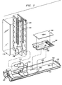
- FIG. 2 shows a splice tray and organizing modules of the cable splicing termination assembly in greater detail;
- FIG. 3 is a side elevation view of the termination assembly of FIG. 1; and
- FIG. 4 is a side elevation view of the termination assembly of FIG. 1 showing several splice trays positioned in an upright manner, and illustrating the routing of tubes containing optical fibers.
- Referring now to FIG. 1A and 1B, which hereinafter will be referred to as FIG. 1, there is shown an optical fiber cable closure which is designated generally by the numeral 20. The
closure 20 includes a cable splicing termination assembly which is designated generally by the numeral 100 and in which optical fibers are spliced/stored and acover 23. Thecover 23 is cylindrically shaped and includes anopen end 25 and aclosed end 27. In order to assemble thecable termination assembly 100 with thecover 23, the cable splicing termination assembly is inserted into theopen end 25 of the cover and moved toward theclosed end 27.Closure 20 is designed to accommodate a plurality of cables to be spliced or can be used to store optical fibers for future splicing to branch cables. - Substantial detail regarding the general construction of cable
splicing termination assembly 100 and cover 23 are contained in U. S. Patents 4,927,227 and 5,185,845 which are hereby incorporated by reference. And although much of the detail is included herein, much is also omitted for the sake of brevity. - As can be seen in FIG. 1, the
cable termination assembly 100 includes acable entry portion 30 and asupport frame 101. Thecable entry portion 30 includes two spacedend plates 34 and 36 - each of which is disc shaped with theend plate 34 being referred to as an outer end plate and theend plate 36 being referred to as an inner end plate. Each of theend plates end plates central stud 38 and three circumferentially-disposed standoffs 39-39 which are molded integrally with theinner end plate 36. Each of the end plates is also provided with three oval-shaped openings with those in theouter end plate 34 being designated 41, 43 and 45; and with those in theinner end plate 36 being designated 47, 48 and 49. Openings in theend plate 34 are aligned with associated ones of the openings in theend plate 36. For example, opening 41 is aligned with theopening - Disposed in the
opening 43 is agrommet 50 which is made from an elastomeric material. Thegrommet 50 includes two passageways 52-52 through which are destined to extend cables 28-28 (see FIG. 4) to be spliced. Similarly, agrommet 54 which is aligned with thegrommet 50 and which includes two passageways 56-56 is disposed in theopening 49. Further, thegrommet 50 is provided with openings 58-58 to allow passage of ground wires therethrough. Although two cables to be spliced are destined to extend through the passageways 52-52 and 56-56 of the alignedgrommets openings inner end plate 36 has a rim thereabout on the inner side of the inner end plate. In this way, the grommets in the inner end plate are prevented from moving through the inner end plate. - Unless it is known from the outset that more than two cables are to be spliced in the
closure 20, the other two sets of aligned openings in the end plates are plugged with dummy plugs 60-60. Advantageously, as more cables need to be spliced in theclosure 20, the dummy plugs are removed and replaced with a pair of grommets identical to thegrommets - Outboard of the
outer end plate 34 is situated aretainer yoke 62 which includes three equiangularly extending ribs 64-64. Thecentral stud 38 which is secured to theend plates knob 61 is turned into the stud to hold the yoke secured in place. Theyoke 62 functions to hold the plugs and grommets in place and to stabilize the closure structure. Each of the ribs 64-64 terminates in across member 65 and includes two strain-relief portions 63-63 which extend angularly therefrom. An end of strain-relief portion 63 is provided with a V-shaped configuration which is such that it provides support for any expected size cable to be spliced with theclosure 20. Each entering cable is secured to an associated strain-relief portion 63 by a cable tie (not shown). The ribs 64-64, as well as the strain-relief portions 63-63 and cross members 65-65, extend for a distance of about 0.75 inch and intersect with a back-upplate 66. No matter which size cable of the expected range of sizes is routed into the closure, the cable engages one of the strain-relief portions 63-63 outside the grommet and hence is prevented from bending excessively at the entrance to the grommet. - Further, between the
yoke 62 and theend plate 34 are disposed three arcuately shaped members 67-67, each of which extends between two pins (not shown) that extend in a direction that is perpendicular to theyoke 62. The members 67-67 are effective to hold the grommets and plugs in place in theouter end plate 34. - Disposed between the
end plates inner grommet 54 to the splice area. Also, a portion of the metallic shield is removed so that only a relatively short length extends beyond the end of the plastic jacket. - A cable
sheath gripping assembly 70, comprising sheath-grip body 71 and sheath-grip clamp 72, attaches to the pair of cables that extend through the grommet openings. Should any two aligned openings in the grommets not have a cable portion therein. a plastic rod is inserted between the grommets and into the openings so as to seal the two aligned openings. Forces are caused to be applied to the jacket of the cable by the turning of bolt (not shown) which extends through anopening 74 inclamp 72 and intoend block 75 which contains a threadedinsert 73. A pair of channels having arcuate ribs are positioned on either side of theend block 75. The ribs are such that they dig into the cable jacket -- thereby clamping the cable and preventing relative movement between the cables and the end plate assembly. Additional detail regarding the construction of the cable sheath griping assembly, and the way it fits into the compact cable closure, is contained in U. S. Patent 5,280,556 which is hereby incorporated by reference. - Each of the end plates cooperates with the
cover 23 to seal the closure against the unintended ingress of contaminants. The outer andinner end plates termination assembly 100 and cover 23) is placed an O-ring which is made from a compliant sealing material. Thecover 23 is formed with astep 147 which. upon assembly, cooperates with the O-ring about the inner end-plate 36 to provide an additional seal. - After the
closure 20 has been assembled, it may be pressure tested at 69 kPa to determine if it leaks. This is accomplished viaport 160, located at the closed end of the cover, where pressurized gas is introduced. The pressure must be removed before opening the closure. - Also provided are facilities for positioning the
closure 20 for splicing operations. An end of thetermination assembly 100 is provided with a slottedopening 170 to receive an end of asupport foot 172. After the support foot is inserted into the opening, the support foot may be placed in engagement with any flat or substantially flat surface to cooperate with theouter end plate 34 to stabilize thetermination assembly 100 so that splicing can be performed. When not being used, thefoot 172 may be stored in an opposite end at the opening and protrude into the cover for future use. - Referring now to FIG. 2, a more detailed description of the cable
splicing termination assembly 100 is provided. Theassembly 100 includes asupport frame 101 having sidewalls 102-102 and anend dam 104 at itsfree end 105. Mounted onframe 101 is anoptical fiber breakout 140 which includes tabs 143-143 that cooperate with slots 103-103 in the frame for securing it relative to the frame.Fiber breakout 140 functions to re-group optical fibers from a cable into various tubes 29-29 (see FIG. 4) for routing to thevarious splice trays 120. Each group of fibers from the cable is received in a channel formed between partitions in one end of thefiber breakout 140. Within thefiber breakout 140, the optical fibers are organized and inserted in predetermined groups into plastic routing tubes. The tubes are arranged so that one end portion of each is received in a channel formed between partitions at the opposite end of the fiber breakout; that is, the end oriented toward thefree end 105 of theframe 101.Fiber breakout cover 139 is positioned on top ofbreakout 140 to protect the bared, coated optical fibers therein. - After the tubes emerge from the
breakout 140, each of the tubes is routed in a retroflexed configuration and directed back toward theinner end plate 36. In that direction, the tubes are routed and secured to selected ones of a plurality of trays 120-120 for the purpose of splicing. Within the free end portion ofsupport frame 101 is disposed afoam pad 117 which is received overpin 121 to cushion fibers which are stored in loops between the breakout 140 and thefree end 105 during handling. - Also mounted on
support frame 101 is awireform 110 which snap locks thereinto. The wireform is illustratively shown as a single piece-part, although it could comprise a pair of spaced-apart parallel tracks that are inserted into bosses, for example, in the frame. As shown,wireform 110 is a generally U-shaped metal structure whose top andbottom sections center section 112. The center section comprises a pair of spaced-apart parallel tracks which function to hold and guidesplice trays 120 mounted thereon. Molded intosupport frame 101 are a number of features 106-106 that are shaped to receive and support thebottom section 113 of the U-shaped wireform without the use of fasteners. In the preferred embodiment of the invention, the top section 111 I ofwireform 110 is bent at a right angle with respect to itscenter section 112. The top section not only limits the upward travel ofsplice trays 120 positioned onparallel tracks 112, it also serves as a support member for storing trays in an upright position while splicing activity takes place in another (horizontally disposed) tray. Preferably the wireform is made from steel because it needs to deal with high stress concentrations when storing trays in the upright position or if the closure is dropped. - Advantageously,
wireform 110 eliminates the need for the stair-stepped hinging arrangements of the prior art. By enabling the trays to be stacked exactly on top of each other, a more compact closure is achieved. Moreover, congestion is minimized in the region where tubes containing optical fibers enter the trays; and it is easier to add splice trays to the closure by using spaced-apart parallel tracks. - Trays 120-120 are secured to frame 101 and individually hold a number of optical fiber splices. Illustratively, each
tray 120 is made of a plastic material such as polycarbonate, and is adapted to be mounted onwireform 110. Eachtray 120 includes a pair of spaced-apart connecting members (cylindrical openings) 128-128 which are positioned to receivewireform 110 so that it can be slideably moved along the wireform. (It is noted at this point that such slideable movement can also be achieved by the use of pins that extend from opposite sides of a tray at one end thereof. These pins can be captured by a pair of parallel grooves that are molded into the sidewalls of the support frame. Naturally, thesupport frame 101 shown in FIG. 2 would need to be modified by extending its sidewalls 102-102 upwardly in the region where the pins are located.) Eachtray 120 also has associated therewith aplate 130 which extends across the tray at the optical fiber entrance end, and includes pins which are received in mating openings in the tray.Plate 130 includes a pair of spaced-apart openings 138-138 which are positioned to accommodatewireform 110.Plate 130 secures incoming tubes of optical fibers or ribbons within channels 123-123. A portion of each tube or ribbon, which is disposed in achannel 123, is wrapped with a foam strip having an adhesive layer that engages surfaces of the tube or ribbons to secure it within the channel. The plate covers these channels thereby securing the tubed fibers or ribbons from unintentional movement. Additionally,tongue 133 serves to restrain loops of slack fiber from being dislodged from thetray 120. - Further, each
tray 120 includes a plurality of overhanging portions 127-127. Optical fibers extending from the tubes which enter the trays through channels 123-123 are routed under these portions 127-127 before being turned in toward splicing portions of the tray. - Mounted within each
tray 120 are one ormore organizing modules 125 for supporting a plurality of commercially available splicing arrangements. Illustratively, eachmodule 125 includes a compliant material (e.g., cellular plastic foam) for holding up to six splices. The compliant material is capable of being compressed as a splicing connector is inserted and to re configure itself about the splicing connector in order to hold it securely within an associated nest. Additional detail regarding the design of these modules 125-125 is contained in U. S. Patent 5,185,845 which has already been incorporated by reference. - After splicing has been completed, the craftsperson places a
protective cover 119 over theoutermost tray 120. (It is noted that the present invention enables the craftsperson to place protective covers over any of the trays because variable tray thickness is possible, whereas the stair-step hinge designs of the prior art are not so accommodating.) The craftsperson then assembles thesplicing termination assembly 100 to thecover 23. Thetermination assembly 100 is inserted into thecover 23 and a clamping band 201 (see FIG. 1) is caused to be disposed about a rim of the cover and theouter end plate 34. Theclamping band 201 is tightened about the cover and the end plate to secure them together and to hold the termination assembly in thecover 23. Each of the end plates cooperate with thecover 23 to seal the closure against the unintended ingress of contaminants or the egress of pressurized air. - Shown in FIGS. 3 and 4 are side elevation views. in partial cross section. of the cable
splicing termination assembly 100 of FIG. 1. In particular. FIG. 3 illustrates the vertical stacking of eight trays 120-1 through 120-8 and the manner in which wireform 110 attaches to supportframe 101. Molding details 106-106 in theframe 101 cooperate with thebottom section 113 of the wireform to secure them together in an easily assembled manner. Uprightparallel tracks 112 maintain the trays in a compact vertical alignment. And although not shown, a "hook and loop" -type fastener (Velcro® fastener for example) wraps around the stack of trays and the support frame to firmly hold them together and prevent unintended relative movement during handling. - FIG. 4 illustrates the manner in which optical fibers are routed within the cable termination assembly. For example, cables 28-28
enter assembly 100 at the left-hand side of FIG. 4 and proceed directly to one end ofbreakout 140 where optical fibers are re-grouped into tubes 29-29. These tubes emerge from the other end ofoptical fiber breakout 140 and are routed to thevarious splice trays 120. The tubes are first routed toward thefree end 105 ofsupport tray 101. and then, in a retroflexed configuration, toward thecable entry end 107. FIG. 4 also illustrates the utility of the top section ofwireform 110. Trays 120-1 through 120-4 are shown in a stored upright position on thetop section 111 ofwireform 110 in order to enable a craftsperson to perform splicing operations within splice tray 120-5. Trays 120-5 through 120-8 are shown in their normal horizontal position attached toparallel track members 112. - Although a particular embodiment of the invention has been shown and described, it is understood that various modifications are possible within the spirit and scope of the invention. These modifications include, but are not limited to the use of non-metallic parallel tracks to hold the trays, the use of other techniques for attaching the parallel tracks to the support frame, and the use of the present invention in a closure that is open at both ends. Additionally, the parallel tracks of the present invention might also comprise grooves in the sidewalls of the support frame which cooperate with pins in the trays and enable the trays to be slideably mounted within the support frame.
Claims (8)
- A compact closure (20) for cables containing optical fiber, said closure comprising a cable termination assembly (100) surrounded by a protective cover (23). the cable termination assembly comprising a support frame (101) and a plurality of fiber connection trays (120) mounted on the support frame for storing loops of fiber therein; each tray being adapted to hold at least one optical fiber connecting arrangement. and each tray including a pair of spaced-apart openings (128) outside the loop of optical fiber through one side of the tray.CHARACTERIZED BYa pair of spaced-apart parallel rods (112) attached to the support frame and extending upwardly therefrom through the openings in each tray, said openings being slideably joined to the pair of parallel rods.
- The closure (20) of claim 1 wherein the parallel rods (112) are cylindrical and metallic, and the openings (128) comprise cylindrical holes in the fiber connection tray (120).
- The closure (20) of claim 2 wherein the parallel rods (112) are made from steel.
- The closure (20) of claim 2 wherein the cylindrical rods (112) comprise a center section of a generally U-shaped wireform (110) whose top and bottom sections (111, 113) reside in different parallel planes - each being perpendicular to the center section.
- The closure (20) of claim 4 wherein the support frame (101) includes a plurality of molded details (106) that are shaped to receive and support the bottom section (113) of the U-shaped wireform (110) without the use of fasteners.
- The closure (20) of claim 1 wherein each tray (120) includes at least one organizing module (125) which is mounted therein, each module including compliant means for holding a plurality of optical fiber connective arrangements which may include different kinds of connective arrangements.
- The optical fiber closure (20) of claim 2, wherein said closure includes optical fiber breakout means (140) into which optical fibers from each cable (28) to be spliced extend for facilitating the transition between optical fibers as grouped in the cables to be spliced and groups of fibers to be spliced on said trays (120), and out of which extend a plurality of tubes (29), each said tube having at least one optical fiber disposed therein and extending from said optical fiber breakout into a tray.
- The closure (20) of claim 1 wherein the cover (23) is substantially cylindrical having a closed end (27) and an open end (25), said cable termination assembly (100) being inserted into the open end of the cover.
Applications Claiming Priority (2)
| Application Number | Priority Date | Filing Date | Title |
|---|---|---|---|
| US08/330,417 US5481639A (en) | 1994-10-28 | 1994-10-28 | Compact closure for optical fiber cable |
| US330417 | 1994-10-28 |
Publications (2)
| Publication Number | Publication Date |
|---|---|
| EP0709701A1 true EP0709701A1 (en) | 1996-05-01 |
| EP0709701B1 EP0709701B1 (en) | 2002-08-07 |
Family
ID=23289685
Family Applications (1)
| Application Number | Title | Priority Date | Filing Date |
|---|---|---|---|
| EP95307426A Expired - Lifetime EP0709701B1 (en) | 1994-10-28 | 1995-10-18 | Compact closure for optical fiber cable |
Country Status (5)
| Country | Link |
|---|---|
| US (1) | US5481639A (en) |
| EP (1) | EP0709701B1 (en) |
| JP (1) | JP3034788B2 (en) |
| CN (1) | CN1087433C (en) |
| DE (1) | DE69527689T2 (en) |
Families Citing this family (46)
| Publication number | Priority date | Publication date | Assignee | Title |
|---|---|---|---|---|
| US5590234A (en) * | 1995-03-31 | 1996-12-31 | Minnesota Mining And Manufacturing Company | Fiber optic splice organizers |
| NZ303594A (en) * | 1995-03-31 | 1999-01-28 | Minnesota Mining & Mfg | Optical fibre splice tray arrangement |
| TW286371B (en) * | 1995-03-31 | 1996-09-21 | Minnesota Mining & Mfg | |
| AU701842B2 (en) * | 1995-04-20 | 1999-02-04 | Preformed Line Products Company | Optical fiber splice case |
| US5631993A (en) * | 1995-04-20 | 1997-05-20 | Preformed Line Products Company | Optical fiber splice case |
| US5611016A (en) * | 1996-06-07 | 1997-03-11 | Lucent Technologies Inc. | Dispersion-balanced optical cable |
| AU4672497A (en) * | 1996-10-10 | 1998-05-05 | Tyco Submarine Systems Ltd. | Submarine fiber-optic cable joint with load-bearing casing |
| US5774618A (en) * | 1996-12-19 | 1998-06-30 | Lucent Technologies Inc. | Compact closure for optical fiber cable |
| JP3722942B2 (en) * | 1997-02-18 | 2005-11-30 | 株式会社フジクラ | Fiber optic cable termination box |
| US5824961A (en) * | 1997-04-30 | 1998-10-20 | Lucent Technologies Inc. | Central strength member anchor for optical fiber cables |
| US5862290A (en) * | 1997-05-01 | 1999-01-19 | Lucent Technologies Inc. | Optical fiber cable splice closure |
| US5907653A (en) * | 1997-05-01 | 1999-05-25 | Lucent Technologies Inc. | Racetrack grommet for optical fiber cable splice closure |
| US5896486A (en) * | 1997-05-01 | 1999-04-20 | Lucent Technologies Inc. | Mass splice tray for optical fibers |
| JP3510460B2 (en) * | 1997-10-09 | 2004-03-29 | 古河電気工業株式会社 | Optical cable connection box |
| WO1999042882A1 (en) * | 1998-02-20 | 1999-08-26 | Alcoa Fujikura Ltd. | Fiber optic splice enclosure |
| US6263141B1 (en) | 1998-09-09 | 2001-07-17 | Adc Telecommunications, Inc. | Optical fiber cable management device including storage tray |
| US6215938B1 (en) * | 1998-09-21 | 2001-04-10 | Adc Telecommunications, Inc. | Fiber optic cabinet and tray |
| US6496640B1 (en) * | 1999-12-16 | 2002-12-17 | Corning Cable Systems Llc | Splice closure with removable and pivotable splice trays, and associated methods |
| US6612515B1 (en) | 2000-08-28 | 2003-09-02 | Adc Telecommunications, Inc. | Telecommunications cable storage spool |
| US6625374B2 (en) | 2001-03-07 | 2003-09-23 | Adc Telecommunications, Inc. | Cable storage spool |
| GB2381081A (en) * | 2001-10-09 | 2003-04-23 | Spirent Plc | Optical fibre splice storage enclosure containing different trays |
| GB0124227D0 (en) * | 2001-10-09 | 2001-11-28 | Spirent Plc | Optical fibre spice storage enclosure |
| US6597845B2 (en) * | 2001-11-07 | 2003-07-22 | Molex Incorporated | Method and apparatus of cross-connecting optical fibers with layered substrates forming fiber optic ribbons |
| CN100374892C (en) * | 2002-04-12 | 2008-03-12 | 泰科电子雷伊化学有限公司 | Optical circuit enclosure |
| GB0314570D0 (en) | 2003-06-23 | 2003-07-30 | Tyco Electronics Raychem Nv | Organiser for optical fibre cables |
| US7027695B2 (en) * | 2003-06-28 | 2006-04-11 | General Dynamics Advanced Information Systems, Inc. | Fiber transition segment for use in optical fiber hydrophone array |
| US6934451B2 (en) * | 2003-06-28 | 2005-08-23 | General Dynamics Advanced Information Systems, Inc. | Mount for use in optical fiber hydrophone array |
| US6865334B2 (en) * | 2003-06-28 | 2005-03-08 | General Dynamics Advanced Information Systems, Inc. | Termination assembly for use in optical fiber hydrophone array |
| US6870997B2 (en) * | 2003-06-28 | 2005-03-22 | General Dynamics Advanced Information Systems, Inc. | Fiber splice tray for use in optical fiber hydrophone array |
| US6879545B2 (en) * | 2003-06-28 | 2005-04-12 | General Dynamics Advanced Information Systems, Inc. | Woven fiber protection cable assembly for use in optical fiber hydrophone array |
| US6904222B2 (en) * | 2003-06-28 | 2005-06-07 | General Dynamics Advanced Information Systems, Inc. | Optical fiber splice protection apparatus for use in optical fiber hydrophone array |
| US7292763B2 (en) * | 2004-03-08 | 2007-11-06 | Adc Telecommunications, Inc. | Fiber access terminal |
| US7045710B1 (en) * | 2005-08-31 | 2006-05-16 | 3M Innovative Properties Company | Enclosure for telecommunication lines and splices |
| US7650055B2 (en) * | 2007-05-31 | 2010-01-19 | Corning Cable Systems Llc | Terminal with internal environmental seal |
| US7697812B2 (en) * | 2008-01-18 | 2010-04-13 | 3M Innovative Properties Company | Enclosure and organizer for telecommunication lines and splices |
| EP2633354A1 (en) | 2010-10-28 | 2013-09-04 | Corning Cable Systems LLC | Impact resistant fiber optic enclosures and related methods |
| MX349876B (en) * | 2011-09-09 | 2017-08-16 | Afl Telecommunications Llc | Splice tray rail system. |
| US9069151B2 (en) | 2011-10-26 | 2015-06-30 | Corning Cable Systems Llc | Composite cable breakout assembly |
| US8873926B2 (en) | 2012-04-26 | 2014-10-28 | Corning Cable Systems Llc | Fiber optic enclosures employing clamping assemblies for strain relief of cables, and related assemblies and methods |
| US10520695B2 (en) | 2013-12-18 | 2019-12-31 | CommScope Connectivity Belgium BVBA | Cable fixation devices and methods |
| JP6031061B2 (en) * | 2014-04-04 | 2016-11-24 | 日本通信電材株式会社 | closure |
| US10509189B2 (en) * | 2015-09-25 | 2019-12-17 | Commscope Technologies Llc | Tray assembly for a fiber optic system |
| BR102016029000B1 (en) * | 2016-12-09 | 2022-09-13 | Furukawa Industrial S.A. Produtos Elétricos | OPTICAL TERMINATION BOX |
| US9829665B1 (en) | 2017-04-27 | 2017-11-28 | Afl Telecommunications Llc | Fiber optic splice enclosures |
| EP3695260A1 (en) | 2017-10-09 | 2020-08-19 | CommScope Connectivity Belgium BVBA | Cable fixation devices and methods |
| US11327231B2 (en) * | 2019-12-05 | 2022-05-10 | Commscope Technologies Llc | Flexible splice protector assembly and method for preparing same |
Citations (8)
| Publication number | Priority date | Publication date | Assignee | Title |
|---|---|---|---|---|
| JPS60138505A (en) * | 1983-12-27 | 1985-07-23 | Furukawa Electric Co Ltd:The | Optical cable connection box |
| DE8528349U1 (en) * | 1985-10-04 | 1985-11-28 | Siemens AG, 1000 Berlin und 8000 München | Receiving device for at least one fiber optic splice cassette |
| DE3724977A1 (en) * | 1987-07-28 | 1989-02-09 | Siemens Ag | Accommodating device for optical waveguides which are plugged together |
| EP0356942A2 (en) * | 1988-08-29 | 1990-03-07 | Gte Control Devices Of Puerto Rico Incorporated | 1550NM fiber distribution panel |
| US4913522A (en) | 1984-04-11 | 1990-04-03 | Nv Raychem Sa | Electrofit fibre optics butt splice |
| EP0367477A2 (en) * | 1988-10-31 | 1990-05-09 | AT&T Corp. | Optical fiber cable closure |
| EP0490644A1 (en) * | 1990-12-13 | 1992-06-17 | AT&T Corp. | Optical fiber cable closure having enhanced storage capability |
| US5280556A (en) | 1992-09-25 | 1994-01-18 | At&T Bell Laboratories | Cable closure which includes a cable sheath gripping assembly |
Family Cites Families (3)
| Publication number | Priority date | Publication date | Assignee | Title |
|---|---|---|---|---|
| NL7900432A (en) * | 1979-01-19 | 1980-07-22 | Nkf Groep Bv | FIBERGLASS CONNECTION SLEEVE. |
| US4266853A (en) * | 1979-03-12 | 1981-05-12 | Northern Telecom Limited | Device for organizing optical fibers and the like |
| US4679896A (en) * | 1985-09-27 | 1987-07-14 | Preformed Line Products Company | Optical fiber splice organizer |
-
1994
- 1994-10-28 US US08/330,417 patent/US5481639A/en not_active Expired - Fee Related
-
1995
- 1995-10-18 DE DE69527689T patent/DE69527689T2/en not_active Expired - Fee Related
- 1995-10-18 EP EP95307426A patent/EP0709701B1/en not_active Expired - Lifetime
- 1995-10-27 CN CN95117682A patent/CN1087433C/en not_active Expired - Fee Related
- 1995-10-30 JP JP7303404A patent/JP3034788B2/en not_active Expired - Fee Related
Patent Citations (10)
| Publication number | Priority date | Publication date | Assignee | Title |
|---|---|---|---|---|
| JPS60138505A (en) * | 1983-12-27 | 1985-07-23 | Furukawa Electric Co Ltd:The | Optical cable connection box |
| US4913522A (en) | 1984-04-11 | 1990-04-03 | Nv Raychem Sa | Electrofit fibre optics butt splice |
| DE8528349U1 (en) * | 1985-10-04 | 1985-11-28 | Siemens AG, 1000 Berlin und 8000 München | Receiving device for at least one fiber optic splice cassette |
| DE3724977A1 (en) * | 1987-07-28 | 1989-02-09 | Siemens Ag | Accommodating device for optical waveguides which are plugged together |
| EP0356942A2 (en) * | 1988-08-29 | 1990-03-07 | Gte Control Devices Of Puerto Rico Incorporated | 1550NM fiber distribution panel |
| EP0367477A2 (en) * | 1988-10-31 | 1990-05-09 | AT&T Corp. | Optical fiber cable closure |
| US4927227A (en) | 1988-10-31 | 1990-05-22 | At&T Bell Laboratories | Optical fiber cable closure |
| EP0490644A1 (en) * | 1990-12-13 | 1992-06-17 | AT&T Corp. | Optical fiber cable closure having enhanced storage capability |
| US5185845A (en) | 1990-12-13 | 1993-02-09 | At&T Bell Laboratories | Optical fiber closure having enhanced storage capability |
| US5280556A (en) | 1992-09-25 | 1994-01-18 | At&T Bell Laboratories | Cable closure which includes a cable sheath gripping assembly |
Non-Patent Citations (1)
| Title |
|---|
| PATENT ABSTRACTS OF JAPAN vol. 009, no. 304 (P - 409) 30 November 1985 (1985-11-30) * |
Also Published As
| Publication number | Publication date |
|---|---|
| EP0709701B1 (en) | 2002-08-07 |
| CN1131280A (en) | 1996-09-18 |
| DE69527689D1 (en) | 2002-09-12 |
| CN1087433C (en) | 2002-07-10 |
| DE69527689T2 (en) | 2002-11-28 |
| JP3034788B2 (en) | 2000-04-17 |
| US5481639A (en) | 1996-01-02 |
| JPH08234025A (en) | 1996-09-13 |
Similar Documents
| Publication | Publication Date | Title |
|---|---|---|
| EP0709701B1 (en) | Compact closure for optical fiber cable | |
| US5185845A (en) | Optical fiber closure having enhanced storage capability | |
| US5097529A (en) | Space-saving optical fiber cable closure | |
| EP0367477B1 (en) | Optical fiber cable closure | |
| US6507691B1 (en) | Fiber optic splice organizer with splicing tray and associated method | |
| US5911027A (en) | Optical fibre organizer having through port extending between opposite faces thereof | |
| CA2171001C (en) | Optical fibre organizer | |
| US5717811A (en) | Optical fiber organizer | |
| US6542688B1 (en) | Optical fiber splicing and connecting assembly | |
| US5751882A (en) | Optical fibre organizer | |
| WO2000065397A1 (en) | Optical fibre organiser | |
| AU697942B2 (en) | Optical fibre organizer |
Legal Events
| Date | Code | Title | Description |
|---|---|---|---|
| PUAI | Public reference made under article 153(3) epc to a published international application that has entered the european phase |
Free format text: ORIGINAL CODE: 0009012 |
|
| AK | Designated contracting states |
Kind code of ref document: A1 Designated state(s): DE FR |
|
| 17P | Request for examination filed |
Effective date: 19961018 |
|
| 17Q | First examination report despatched |
Effective date: 20010404 |
|
| GRAG | Despatch of communication of intention to grant |
Free format text: ORIGINAL CODE: EPIDOS AGRA |
|
| GRAG | Despatch of communication of intention to grant |
Free format text: ORIGINAL CODE: EPIDOS AGRA |
|
| GRAH | Despatch of communication of intention to grant a patent |
Free format text: ORIGINAL CODE: EPIDOS IGRA |
|
| GRAH | Despatch of communication of intention to grant a patent |
Free format text: ORIGINAL CODE: EPIDOS IGRA |
|
| GRAA | (expected) grant |
Free format text: ORIGINAL CODE: 0009210 |
|
| AK | Designated contracting states |
Kind code of ref document: B1 Designated state(s): DE FR |
|
| REF | Corresponds to: |
Ref document number: 69527689 Country of ref document: DE Date of ref document: 20020912 |
|
| PGFP | Annual fee paid to national office [announced via postgrant information from national office to epo] |
Ref country code: FR Payment date: 20021002 Year of fee payment: 8 |
|
| PGFP | Annual fee paid to national office [announced via postgrant information from national office to epo] |
Ref country code: DE Payment date: 20021031 Year of fee payment: 8 |
|
| ET | Fr: translation filed | ||
| PLBE | No opposition filed within time limit |
Free format text: ORIGINAL CODE: 0009261 |
|
| STAA | Information on the status of an ep patent application or granted ep patent |
Free format text: STATUS: NO OPPOSITION FILED WITHIN TIME LIMIT |
|
| 26N | No opposition filed |
Effective date: 20030508 |
|
| PG25 | Lapsed in a contracting state [announced via postgrant information from national office to epo] |
Ref country code: DE Free format text: LAPSE BECAUSE OF NON-PAYMENT OF DUE FEES Effective date: 20040501 |
|
| PG25 | Lapsed in a contracting state [announced via postgrant information from national office to epo] |
Ref country code: FR Free format text: LAPSE BECAUSE OF NON-PAYMENT OF DUE FEES Effective date: 20040630 |
|
| REG | Reference to a national code |
Ref country code: FR Ref legal event code: ST |