EP0709582A2 - Cubic connector structure for connecting frame bars and method of producing same - Google Patents
Cubic connector structure for connecting frame bars and method of producing same Download PDFInfo
- Publication number
- EP0709582A2 EP0709582A2 EP95307540A EP95307540A EP0709582A2 EP 0709582 A2 EP0709582 A2 EP 0709582A2 EP 95307540 A EP95307540 A EP 95307540A EP 95307540 A EP95307540 A EP 95307540A EP 0709582 A2 EP0709582 A2 EP 0709582A2
- Authority
- EP
- European Patent Office
- Prior art keywords
- main part
- forming
- connector
- side walls
- hole
- Prior art date
- Legal status (The legal status is an assumption and is not a legal conclusion. Google has not performed a legal analysis and makes no representation as to the accuracy of the status listed.)
- Withdrawn
Links
Images



Classifications
-
- A—HUMAN NECESSITIES
- A47—FURNITURE; DOMESTIC ARTICLES OR APPLIANCES; COFFEE MILLS; SPICE MILLS; SUCTION CLEANERS IN GENERAL
- A47B—TABLES; DESKS; OFFICE FURNITURE; CABINETS; DRAWERS; GENERAL DETAILS OF FURNITURE
- A47B47/00—Cabinets, racks or shelf units, characterised by features related to dismountability or building-up from elements
- A47B47/0016—Node corner connectors, e.g. cubic
-
- A—HUMAN NECESSITIES
- A47—FURNITURE; DOMESTIC ARTICLES OR APPLIANCES; COFFEE MILLS; SPICE MILLS; SUCTION CLEANERS IN GENERAL
- A47B—TABLES; DESKS; OFFICE FURNITURE; CABINETS; DRAWERS; GENERAL DETAILS OF FURNITURE
- A47B2230/00—Furniture jointing; Furniture with such jointing
- A47B2230/04—Cubic corner parts joining sectional strips for furniture
-
- Y—GENERAL TAGGING OF NEW TECHNOLOGICAL DEVELOPMENTS; GENERAL TAGGING OF CROSS-SECTIONAL TECHNOLOGIES SPANNING OVER SEVERAL SECTIONS OF THE IPC; TECHNICAL SUBJECTS COVERED BY FORMER USPC CROSS-REFERENCE ART COLLECTIONS [XRACs] AND DIGESTS
- Y10—TECHNICAL SUBJECTS COVERED BY FORMER USPC
- Y10T—TECHNICAL SUBJECTS COVERED BY FORMER US CLASSIFICATION
- Y10T403/00—Joints and connections
- Y10T403/34—Branched
- Y10T403/341—Three or more radiating members
-
- Y—GENERAL TAGGING OF NEW TECHNOLOGICAL DEVELOPMENTS; GENERAL TAGGING OF CROSS-SECTIONAL TECHNOLOGIES SPANNING OVER SEVERAL SECTIONS OF THE IPC; TECHNICAL SUBJECTS COVERED BY FORMER USPC CROSS-REFERENCE ART COLLECTIONS [XRACs] AND DIGESTS
- Y10—TECHNICAL SUBJECTS COVERED BY FORMER USPC
- Y10T—TECHNICAL SUBJECTS COVERED BY FORMER US CLASSIFICATION
- Y10T403/00—Joints and connections
- Y10T403/44—Three or more members connected at single locus
-
- Y—GENERAL TAGGING OF NEW TECHNOLOGICAL DEVELOPMENTS; GENERAL TAGGING OF CROSS-SECTIONAL TECHNOLOGIES SPANNING OVER SEVERAL SECTIONS OF THE IPC; TECHNICAL SUBJECTS COVERED BY FORMER USPC CROSS-REFERENCE ART COLLECTIONS [XRACs] AND DIGESTS
- Y10—TECHNICAL SUBJECTS COVERED BY FORMER USPC
- Y10T—TECHNICAL SUBJECTS COVERED BY FORMER US CLASSIFICATION
- Y10T403/00—Joints and connections
- Y10T403/46—Rod end to transverse side of member
- Y10T403/4602—Corner joint
Definitions
- This invention relates to structures for connecting together a plurality of frame bars at their ends and a method of producing such structures.
- the present invention seeks to eliminate such problems of the prior art technology and to provide safe connector structures which do not have any externally protruding parts and can be attached to frame bars securely and easily.
- the present invention seeks to provide methods of producing such connector structures efficiently.
- a connector structure comprising a main part having side walls with three mutually perpendicular quadrangular outer surfaces and a cover piece which similarly has three side walls with mutually perpendicular quadrangular outer surfaces.
- Each of the side walls of the main part has a hole for allowing a screw to pass therethrough.
- a protruding member for engaging with the cover piece is formed on the inner surfaces of the side walls of the main part, and a protrusion is formed on the inner walls of the cover piece.
- the main part of such a connector structure can be produced by a die-casting method by using only one lower mold piece and one upper mold piece.
- the lower mold piece has an indentation with three mutually perpendicular inner surfaces each making a same angle with the vertical direction for forming the three outer surfaces of the main part.
- the upper mold piece has a convex part for forming the inner surface.
- the cover piece can be produced by an ordinary injection molding method by using similarly designed mold pieces.
- frame bars can be connected together securely and the joint is left with smooth external surfaces with no protrusions, the connector structure preferably becoming a cube after the cover piece is attached to the main part by engaging the protrusion from the cover piece with the engagement member on the main part.
- the invention also teaches how easily the main parts and the cover pieces of this invention can be produced by using only two mold pieces which can be moved toward and away from each other linearly.
- a connector structure according to this invention comprises a main part 1 and a cover piece 2.
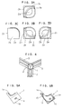
- the main part 1 is made of a metallic material such as aluminum and has three side walls 1a, 1b and 1c, forming a half-open empty space on their internal side, as shown in Figs. 1 and 2.
- the outer surfaces of these side walls 1a, 1b and 1c are mutually perpendicular and are each a square of the same size as the end surfaces of frame bars 3 to be connected thereto.
- the three side walls 1a, 1b, and 1c are each sufficiently thick so as to provide adequate strength required of a connector structure and are each provided with a screw-passing hole 1d at the center.
- the inner surfaces of the three side Walls 1a, 1b and 1c are indented so as to together form a concave surface 15.
- the boundary of this concave surface 15 runs along the peripheries of the three side walls 1a, 1b and 1c, as can be seen in Fig. 1, and protrudes uniquely therefrom, as can be seen in Figs. 1, 5A and 5B, in the direction of an imaginary line which makes the same angle with each of the three mutually perpendicular outer surfaces of the walls 1a, 1b and 1c.
- This unidirectionally protruding boundary of the concave surface 15 serves as an engagement member 1e, as will be explained below more in detail, for tightly attaching the main part 1 to the cover piece 2 when they are in a closed relationship.
- the cover piece 2 is somewhat smaller than the main part 1 but is of a similar structure, as shown in Fig. 3, having three side walls 2a, 2b and 2c with mutually perpendicular outer surfaces to form a half-open empty space on the side of their inner surfaces. These inner surfaces are provided with a protrusion 2e entirely along their peripheries, as shown in Figs. 3A, 3B and 3D, corresponding to the engagement member le on the main part 1 and protruding uniquely in the direction of an imaginary line which makes the same angle with each of the three mutually perpendicular outer surfaces of the side walls 2a, 2b and 2c.
- each side wall 2a, 2b or 2c is substantially square-shaped such that when the main part 1 and the cover piece 2 are thus attached to each other and are in the closed relationship, they together assume a substantially cubic shape, as shown in Fig. 4.
- each frame bar 3 is provided with a screw-receiving opening 3d (tapping hole) at the center of its end surface, as shown in Fig. 1.
- a screw-receiving opening 3d tunnel hole
- one of the side walls 1a, 1b or 1c of the main part 1 is attached to an end surface of one of the frame bars 3 with the screw-passing hole 1d at the center of that side wall aligned with the screw-receiving opening 3d and a screw 4 is passed through them both from the side of the concave surface 15 of the main part 1, thereby securely attaching the main part 1 to the end surface of the first frame bar 3.
- the main part 1 is made of a metallic material such as aluminum
- the cover piece 2 is made of a synthetic resin material such as polyacetal, but other materials may be selected as long as adequate strength can be obtained for the purpose of serving as a connector structure.
- the main part 1 is manufactured by a die-casting method and the cover piece by a general injection molding method, both methods requiring appropriate mold pieces.
- the method of this invention not only requires only two mold pieces but they can be moved toward or away from each other to be engaged together or to be separated from each by moving one of them linearly along a single straight line with respect to the other.
- a lower mold piece 10 for forming the outer surfaces of the side walls 1a, 1b and 1c and an upper mold piece 20 for forming the concave inner surface 15 and the engagement member le therearound, as shown in Fig. 6.
- the lower mold piece 10 has a horizontal top surface provided with an indentation in the form of a triangular pyramid with three mutually perpendicular inner surfaces 11 (as shown more clearly in Fig. 8A) for the purpose of forming the mutually perpendicular outer surfaces of the three side walls 1a, 1b and 1c of the main part 1.
- Each of these three mutually perpendicular inner surfaces 11 makes the same angle with the vertical direction (that is, the direction perpendicular to the horizontal top surface).
- Fig. 5A shows the main part 1 as oriented when formed inside the lower mold piece 10.
- the upper mold piece 20 has a horizontal bottom surface provided with a convex part 22 for forming the concave inner surface 15. Both the inner surfaces 11 of the indentation in the lower mold piece 10 and the convex part 22 of the upper mold piece 20 are provided with small protrusions 10a and 20a for forming the screw-passing holes 1d through the side walls 1a, 1b and 1c. These small hole-forming protrusions 10a and 20a are shaped and positioned with respect to each other as shown in Fig.
- mold pieces are formed, as shown in Figs. 8A and 8B, for example, for achieving mass production such that a plurality of main parts 1 can be produced simultaneously.
- Mold pieces for mass production of the cover pieces 2 by an injection molding method are similarly designed with a pair of upper and lower mold pieces which can be brought towards and moved away from each other by a linear motion along a single straight line (the vertical line) with respect to the other and provide three mutually perpendicular surfaces making a same angle to the direction of this straight line.
- the manner of using the connector structure according to the present invention has been illustrated above with reference only to Figs. 1 and 4, it goes without saying that it can be used in a variety of different ways.
- it may be used for connecting only two frame bars 3 as shown in Fig. 9A.
- a masking cap 5d is inserted into the remaining screw-passing hole ld of the main part 1 such that it can be hidden.
- two of the connector structures of the invention are used, each at one of the longitudinal edge part of the end surfaces.
- a short bar 6 is inserted between the two connector structures to complete a joint without unevenness in the exterior.
- 9C shows a situation where three frame bars 3 with different cross-sectional shapes are connected. It should be clear to a person skilled in the art, from these illustrated examples, how connector structures of this invention can be used in many different situations without leaving any surface protrusions or indentations at the joint.
- the connector structures according to the present invention are capable of connecting two or three frame bars securely at their ends and without leaving surface protrusions or indentations such that externally exposed surfaces are all smooth. This makes the joints not only sightly but also safe for the operators to work around.
- the method of producing such connector structures according to this invention is advantageous in that only two mold pieces are required. This not only simplifies the production process but also reduces the cost of producing the mold significantly.
Landscapes
- Mutual Connection Of Rods And Tubes (AREA)
- Moulds, Cores, Or Mandrels (AREA)
- Moulds For Moulding Plastics Or The Like (AREA)
- Adornments (AREA)
Abstract
A connector structure for connecting together a plurality of elongated frame bars at their ends includes a main part having three side walls with mutually perpendicular quadrangular outer surfaces and a cover piece also having three side walls with mutually perpendicular outer surfaces such that they together assume a cubic form when they are attached to each other in a closed relationship with an engagement member on the inner surfaces of the three walls of the main part and a protrusion on the cover piece engaged to each other. Each side wall of the main part is provided with a throughhole for passing a screw therethrough such that it can be attached to end surface of a frame bar. Such main part is produced by using only two mold pieces, an upper molding piece with a convex part and a lower molding piece with an indentation. The indentation has three inner surfaces, each making a same angle to the vertical direction. Each of the screw-passing throughholes is formed by two small hole-forming protrusions, one protruding vertically downward from the convex part of the upper molding piece and the other protruding vertically upward from one of the sloped inner surfaces of the lower molding piece. Each hole-forming protrusions have a vertical wall such that a pair of upward and downward protrusions can be put next to each other.
Description
- This invention relates to structures for connecting together a plurality of frame bars at their ends and a method of producing such structures.
- For connecting together elongated construction materials such as frame bars at their ends, it has been known, as shown in Fig. 10, to attach an L-
shaped metal bracket 31 on the surface of eachframe bar 3, leaving an end surface 3a of one of them exposed to the exterior. Frame bars thus connected, however, are not sightly because the metal brackets used to connect them together protrude from their side surfaces. Such metal brackets, as well as screws which are used to attach them to the frame bars, can be a source of serious accidents because they can easily catch a part of the worker's clothes. - The present invention seeks to eliminate such problems of the prior art technology and to provide safe connector structures which do not have any externally protruding parts and can be attached to frame bars securely and easily.
- Further, the present invention seeks to provide methods of producing such connector structures efficiently.
- According to the present invention, there is provided a connector structure comprising a main part having side walls with three mutually perpendicular quadrangular outer surfaces and a cover piece which similarly has three side walls with mutually perpendicular quadrangular outer surfaces. Each of the side walls of the main part has a hole for allowing a screw to pass therethrough. A protruding member for engaging with the cover piece is formed on the inner surfaces of the side walls of the main part, and a protrusion is formed on the inner walls of the cover piece. When the main part and the cover piece are attached to each other by engaging the engagement member on the main part and the protrusion from the cover piece, the main part and the cover piece together assume a single cubic shape with smooth outer surfaces.
- The main part of such a connector structure can be produced by a die-casting method by using only one lower mold piece and one upper mold piece. The lower mold piece has an indentation with three mutually perpendicular inner surfaces each making a same angle with the vertical direction for forming the three outer surfaces of the main part. The upper mold piece has a convex part for forming the inner surface. For forming the screw-passing holes through the side walls, while allowing the upper mold piece to be moved towards or away from the lower mold piece linearly along a single straight line, small protrusions are formed both downward from the convex part of the upper mold piece and upward from the inner surfaces of the lower mold piece, both having vertical surfaces such that, as the two mold pieces are moved toward each other, pairs of these protrusions from the upper and lower mold pieces slide against and come to contact with each other across their vertical surfaces.. The cover piece can be produced by an ordinary injection molding method by using similarly designed mold pieces.
- With connector structures according to this invention, frame bars can be connected together securely and the joint is left with smooth external surfaces with no protrusions, the connector structure preferably becoming a cube after the cover piece is attached to the main part by engaging the protrusion from the cover piece with the engagement member on the main part. The invention also teaches how easily the main parts and the cover pieces of this invention can be produced by using only two mold pieces which can be moved toward and away from each other linearly.
- The accompanying drawings, which are incorporated in and form a part of this specification, illustrate an embodiment of the invention and, together with the description, serve to explain the principles of the invention. In the drawings:
- Fig. 1 is a diagonal view of components of a connector structure embodying this invention before being attached to frame bars;
- Figs. 2A, 2B, 2C and 2D (referred to together as Fig. 2) are views of the main part of the connector structure of Fig. 1 as seen respectively from the top (Fig. 2A), from the front (Fig. 2B), from the left-hand side (Fig. 2C) and from the right-hand side (Fig. 2D);
- Figs. 3A, 3B, 3C and 3D (referred to together as Fig. 3) are views of the cover piece of the connector structure of Fig. 1 as seen respectively from the top (Fig. 3A), from the front (Fig. 3B), from the left-hand side (Fig. 3C) and from the right-hand side (Fig. 3D);
- Fig. 4 is a diagonal external view of the connector structure of Fig. 1 used for connecting three frame bars as an example;
- Fig. 5A is a diagonal external view of the main part of Fig. 1 as taken in the direction of
arrows 5 in Fig. 2D, and Fig. 5B is a sectional view of the same taken along line 5-5 of Fig. 2D; - Fig. 6 is a sectional view of portions of mold pieces for the production of the main part;
- Figs. 7A and 7B are parts of Fig. 6 which are enlarged;
- Figs. 8A and 8B are respectively a plan view and a sectional side view of the lower mold piece of Fig. 7A as a whole;
- Figs. 9A, 9B and 9C are external views of connector structures of this invention used in different situations; and
- Fig. 10 is a diagonal external view of two frame bars connected by means of a prior art connector structure.
- As shown in Fig. 1 by way of an example, a connector structure according to this invention comprises a
main part 1 and acover piece 2. Themain part 1 is made of a metallic material such as aluminum and has threeside walls side walls frame bars 3 to be connected thereto. The threeside walls hole 1d at the center. The inner surfaces of the threeside Walls concave surface 15. The boundary of thisconcave surface 15 runs along the peripheries of the threeside walls walls concave surface 15 serves as anengagement member 1e, as will be explained below more in detail, for tightly attaching themain part 1 to thecover piece 2 when they are in a closed relationship. - The
cover piece 2 is somewhat smaller than themain part 1 but is of a similar structure, as shown in Fig. 3, having threeside walls protrusion 2e entirely along their peripheries, as shown in Figs. 3A, 3B and 3D, corresponding to the engagement member le on themain part 1 and protruding uniquely in the direction of an imaginary line which makes the same angle with each of the three mutually perpendicular outer surfaces of theside walls protrusion 2e of thecover piece 2 to slide inside and thereby engage with the engagement member le of themain part 1 as themain part 1 and thecover piece 2 are attached together when they are in the aforementioned closed relationship. The outer surface of eachside wall main part 1 and thecover piece 2 are thus attached to each other and are in the closed relationship, they together assume a substantially cubic shape, as shown in Fig. 4. - Next will be described a manner in which this connector structure may be used for connecting ends of three frame bars such that they will be mutually perpendicular, as shown in Fig. 4. Each
frame bar 3 is provided with a screw-receiving opening 3d (tapping hole) at the center of its end surface, as shown in Fig. 1. First, one of theside walls main part 1 is attached to an end surface of one of theframe bars 3 with the screw-passinghole 1d at the center of that side wall aligned with the screw-receiving opening 3d and ascrew 4 is passed through them both from the side of theconcave surface 15 of themain part 1, thereby securely attaching themain part 1 to the end surface of thefirst frame bar 3. In identical manners, twoother frame bars 3, each with an end surface similarly provided with a screw-receiving opening 3d, are securely attached to the other two side walls of themain part 1. Thecover piece 2 is thereafter attached to themain part 1 by pushing it in the direction of the imaginary line which makes the same angle to all three outer surfaces of theside walls protrusion 2e of thecover piece 2 with the engagement member le on the inner surfaces of themain part 1. Fig. 4 shows the joint thus completed. - The
main part 1 is made of a metallic material such as aluminum, and thecover piece 2 is made of a synthetic resin material such as polyacetal, but other materials may be selected as long as adequate strength can be obtained for the purpose of serving as a connector structure. According to a preferred method of producing connector structures of this invention as described above, themain part 1 is manufactured by a die-casting method and the cover piece by a general injection molding method, both methods requiring appropriate mold pieces. Although many mold pieces are normally required to form a structure with a concave inner surface such as themain part 1 according to this invention, the method of this invention not only requires only two mold pieces but they can be moved toward or away from each other to be engaged together or to be separated from each by moving one of them linearly along a single straight line with respect to the other. - According to this invention, use is made of a
lower mold piece 10 for forming the outer surfaces of theside walls upper mold piece 20 for forming the concaveinner surface 15 and the engagement member le therearound, as shown in Fig. 6. Thelower mold piece 10 has a horizontal top surface provided with an indentation in the form of a triangular pyramid with three mutually perpendicular inner surfaces 11 (as shown more clearly in Fig. 8A) for the purpose of forming the mutually perpendicular outer surfaces of the threeside walls main part 1. Each of these three mutually perpendicularinner surfaces 11 makes the same angle with the vertical direction (that is, the direction perpendicular to the horizontal top surface). Fig. 5A shows themain part 1 as oriented when formed inside thelower mold piece 10. - The
upper mold piece 20 has a horizontal bottom surface provided with aconvex part 22 for forming the concaveinner surface 15. Both theinner surfaces 11 of the indentation in thelower mold piece 10 and theconvex part 22 of theupper mold piece 20 are provided withsmall protrusions holes 1d through theside walls protrusions upper mold piece 20 is lowered vertically, theprotrusions hole 1d. It is to be noted that neither theconvex part 22 of theupper mold piece 20 nor any of theinner surfaces 11 of thelower mold piece 10 has any horizontally protruding part and hence that theupper mold piece 20 can be lifted vertically upward without any hindrance from thelower mold piece 10. - For practical applications, mold pieces are formed, as shown in Figs. 8A and 8B, for example, for achieving mass production such that a plurality of
main parts 1 can be produced simultaneously. Mold pieces for mass production of thecover pieces 2 by an injection molding method are similarly designed with a pair of upper and lower mold pieces which can be brought towards and moved away from each other by a linear motion along a single straight line (the vertical line) with respect to the other and provide three mutually perpendicular surfaces making a same angle to the direction of this straight line. - Although the manner of using the connector structure according to the present invention has been illustrated above with reference only to Figs. 1 and 4, it goes without saying that it can be used in a variety of different ways. For example, it may be used for connecting only two
frame bars 3 as shown in Fig. 9A. In such an application, amasking cap 5d is inserted into the remaining screw-passing hole ld of themain part 1 such that it can be hidden. When two frame bars with a rectangular cross-sectional shape are connected, as shown in Fig. 9B, two of the connector structures of the invention are used, each at one of the longitudinal edge part of the end surfaces. Ashort bar 6 is inserted between the two connector structures to complete a joint without unevenness in the exterior. Fig. 9C shows a situation where threeframe bars 3 with different cross-sectional shapes are connected. It should be clear to a person skilled in the art, from these illustrated examples, how connector structures of this invention can be used in many different situations without leaving any surface protrusions or indentations at the joint. - In summary, the connector structures according to the present invention are capable of connecting two or three frame bars securely at their ends and without leaving surface protrusions or indentations such that externally exposed surfaces are all smooth. This makes the joints not only sightly but also safe for the operators to work around. The method of producing such connector structures according to this invention is advantageous in that only two mold pieces are required. This not only simplifies the production process but also reduces the cost of producing the mold significantly.
Claims (9)
- A connector for connecting together a plurality of frame bars, comprising a main part with plurality of wall elements (1a, 1b, 1c), each wall element being fixedly securable to a respective one of said plurality of frame bars, characterised in that each wall element is arranged to be secured to an end face of the respective frame bar, and the connector forming a corner structure between the frame bars and further including a cover arranged to be fitted to the wall elements and form the exterior surface of the corner structure, and optionallythe connector, having either two or three wall elements.
- The connector of claim 1, wherein one corner structure including the cover comprises a solid structure, optionally a rhombohedron such as a cube.
- A connector according to claim 1 or claim 2 comprising:the main part (1) which comprises three side walls (1a, 1b, 1c) with mutually perpendicular quadrangular outer surfaces and inner surfaces provided with an engagement member (1e) protruding inwardly therefrom, each of said side walls having a screw-passing hole (1d) therethrough; andthe cover (2) comprises three side walls (2a, 2b, 2c) with mutually perpendicular outer surfaces and inner surfaces provided with a protrusion (2e) adapted to engage with said engagement member (1e) when said main part (1) and said cover piece (2) are in a closed relationship, said main part (1) and said cover piece (2) together forming a cubic shape when in said closed relationship.
- The connector structure of any preceding claim, wherein said engagement member (1e) is formed along peripheries of the inner surfaces of the side walls of said main part (1).
- The connector structure of claim 4, wherein the inner surfaces of the side walls (1a, 1b, 1c) of said main part (1) have indentations which together form a concave surface (15) inside said engagement member (1e), said protrusion (2e) on said cover piece (2) being adapted to engage with said concave surface.
- A method of producing the connector structure of any one of the preceding claims, said method comprising the steps of:providing a lower mold piece (10) and an upper mold piece (20), said lower mold piece (10) having an indentation with three mutually perpendicular oblique surfaces (11) each making a same angle with a specified imaginary line, said oblique surfaces (11) having hole-forming upward protrusions (10a) protruding upward therefrom in the direction of said specified imaginary line for providing said screw-passing holes (1d), said upper mold piece (20) having a convex part (22) for forming the inner surfaces of said main part (1), said convex part (22) having hole-forming downward protrusions (20a) protruding downward therefrom, one each of said hole-forming upward and downward protrusions (10a, 20a) serving together to form one of said screw-passing holes (1d); andmoving said upper mold piece (20) linearly with respect to said lower mold piece (10) along said specified imaginary line.
- Mold pieces for producing by a die-casting process a connector part which has three side walls with mutually perpendicular outer surfaces and inner surfaces forming together a concave surface (15), each of said three side walls having therethrough a screw-passing hole (1d) capable of allowing a screw (4) to pass therethrough, said mold pieces comprising an upper mold piece (20) and a lower mold piece (10), said lower mold piece (10) having an indentation with three mutually perpendicular oblique surfaces (11) each making a same angle with an imaginary vertical line, said oblique surfaces (11) having hole-forming upward protrusions (10a) upward therefrom parallel to said imaginary vertical line for providing said screw-passing holes (1d), said upper mold piece (20) having a convex part (22) for forming the inner surfaces of said connector part, said convex part (22) having hole-forming downward protrusions (20a) protruding downward therefrom parallel to said imaginary vertical line, one each of said hole-forming upward and downward protrusions (10a, 20a) serving together as a pair to form one of said screw-passing holes (1d).
- The mold pieces of claim 7, wherein said hole-forming upward and downward protrusions (10a, 20a) have vertical surfaces which are parallel both mutually and to said imaginary vertical line, each pair of said hole-forming upward and downward protrusions (10a, 20a) being adapted to slide against each other over said vertical surfaces and come to be in contact with each other over said vertical surfaces.
- A frame assembly comprising a plurality of frame bars and a connector according to any one of claims 1 to 5.
Applications Claiming Priority (2)
| Application Number | Priority Date | Filing Date | Title |
|---|---|---|---|
| JP290656/94 | 1994-10-31 | ||
| JP29065694A JP3400573B2 (en) | 1994-10-31 | 1994-10-31 | Manufacturing method of connecting member |
Publications (1)
| Publication Number | Publication Date |
|---|---|
| EP0709582A2 true EP0709582A2 (en) | 1996-05-01 |
Family
ID=17758799
Family Applications (1)
| Application Number | Title | Priority Date | Filing Date |
|---|---|---|---|
| EP95307540A Withdrawn EP0709582A2 (en) | 1994-10-31 | 1995-10-24 | Cubic connector structure for connecting frame bars and method of producing same |
Country Status (5)
| Country | Link |
|---|---|
| US (1) | US5580181A (en) |
| EP (1) | EP0709582A2 (en) |
| JP (1) | JP3400573B2 (en) |
| KR (1) | KR970021558A (en) |
| TW (1) | TW293070B (en) |
Cited By (4)
| Publication number | Priority date | Publication date | Assignee | Title |
|---|---|---|---|---|
| WO2011028211A1 (en) | 2009-09-01 | 2011-03-10 | Emerson Network Power, Energy Systems, North America, Inc. | Telecommunications enclosures |
| CN109906193A (en) * | 2016-09-14 | 2019-06-18 | 卡梅尔·保罗·斯托雷斯 | A corner connector and the container containing the connector |
| CN110285118A (en) * | 2019-07-01 | 2019-09-27 | 贵州锦程铝业科技有限公司 | A kind of corner connecting parts applied to sectional material of cabinet body connection |
| GB2625554A (en) * | 2022-12-20 | 2024-06-26 | Haefele Uk Ltd | A Corner Connector |
Families Citing this family (44)
| Publication number | Priority date | Publication date | Assignee | Title |
|---|---|---|---|---|
| DE59504612D1 (en) * | 1994-07-25 | 1999-02-04 | Alusuisse Lonza Services Ag | Fastener |
| US5688086A (en) * | 1996-02-16 | 1997-11-18 | Aluminum Company Of America | Standard corner fittings for aluminum container frames |
| DE29706040U1 (en) * | 1997-04-05 | 1998-07-30 | Pies, Gerrit, 42659 Solingen | Corner connector |
| DE19751165A1 (en) * | 1997-11-19 | 1999-05-20 | Bosch Gmbh Robert | mounting brackets |
| US5918999A (en) * | 1998-03-27 | 1999-07-06 | Lamarca; Guy M. | Geometric spacial frame assembly |
| DE19817421A1 (en) * | 1998-04-18 | 1999-10-21 | Bosch Gmbh Robert | Element for connecting flat protective fence elements |
| US6044990A (en) * | 1998-05-22 | 2000-04-04 | Palmeri; Richard P. | Modular rack system and components therefor |
| CH705434B1 (en) * | 2000-01-05 | 2013-03-15 | Syma Intercontinental Sa | Cube-shaped profile element and sealing strip for this purpose. |
| US6854238B2 (en) * | 2002-11-12 | 2005-02-15 | Alfred Boots | Structural connection system for frameworks |
| USD484780S1 (en) | 2003-04-29 | 2004-01-06 | Daniel Paul Chairs, Llc | Corner coupling for a chair frame |
| DE102006003349A1 (en) * | 2006-01-23 | 2007-08-30 | Bsw-Anlagenbau Gmbh | Equipment cabinet with a cuboid cabinet framework made of profiles, with bolted corner connectors |
| US20080016789A1 (en) * | 2006-07-18 | 2008-01-24 | Boots Alfred H | Spherical hub for modular structure system |
| JP4953307B2 (en) * | 2007-06-28 | 2012-06-13 | 河淳株式会社 | Pedestal cover, pedestal and pedestal structure |
| US7677010B2 (en) * | 2007-07-03 | 2010-03-16 | Boots Alfred H | Modular structural system |
| TWD128306S1 (en) * | 2007-10-24 | 2009-04-11 | 股份有限公司 | Structural post material |
| TWD128304S1 (en) * | 2007-10-24 | 2009-04-11 | 股份有限公司 | Structural post material |
| TWD128305S1 (en) * | 2007-10-24 | 2009-04-11 | 股份有限公司 | Structural post material |
| US8511623B1 (en) * | 2009-07-30 | 2013-08-20 | SNK Innovations, LLC | Conduit hardware and related assemblies and methods |
| CH702646A1 (en) | 2010-02-05 | 2011-08-15 | Rotho Kunststoff Ag | Corner connectors, ESPECIALLY Corner connector for MODULAR FURNITURE SYSTEMS. |
| US8707653B2 (en) * | 2010-07-01 | 2014-04-29 | Michael J. Calleja | Modular truss system with six-way connector boxes |
| US11246231B2 (en) | 2012-02-10 | 2022-02-08 | Chatsworth Products, Inc. | Door closer mechanism for hot/cold aisle air containment room |
| US20140196394A1 (en) | 2013-01-11 | 2014-07-17 | Chatsworth Products, Inc. | Modular thermal isolation barrier for data processing equipment structure |
| USD720608S1 (en) * | 2013-01-22 | 2015-01-06 | Toyoda Products Co., Ltd. | Pipe connector for furniture kits |
| WO2014163964A1 (en) * | 2013-03-13 | 2014-10-09 | Conxtech, Inc. | Modular, faceted, block-and-shell node system for connecting elongate frame elements |
| US10501929B2 (en) * | 2013-09-30 | 2019-12-10 | Drew P. HENRY | Hollow connector sleeve with interlocking components |
| US20150129527A1 (en) * | 2013-11-11 | 2015-05-14 | Atomic Energy Council - Institute Of Nuclear Energy Research | Frame structure of solar cell module |
| US9351427B2 (en) | 2013-12-17 | 2016-05-24 | Chatsworth Products, Inc. | Electronic equipment enclosure |
| US9578772B2 (en) | 2014-09-05 | 2017-02-21 | Emerson Network Power, Energy Systems, North America, Inc. | Cabinet frame enclosures, frame members and corresponding methods |
| WO2017024379A1 (en) * | 2015-08-12 | 2017-02-16 | Akhavan-Tabassi Payman | Knockdown containers and displays with optional lighting features |
| US10501928B2 (en) * | 2015-12-16 | 2019-12-10 | Flexlink Ab | Split connector and modular frame comprising such a split connector |
| US10575633B2 (en) * | 2015-12-22 | 2020-03-03 | LDR Global Industries, LLC | Pipe rack system |
| FR3053486B1 (en) * | 2016-07-01 | 2018-07-20 | Bull Sas | FLOOR LOAD DISTRIBUTION SYSTEM FOR COMPUTER CABINET |
| WO2018022721A1 (en) | 2016-07-26 | 2018-02-01 | Chatsworth Products, Inc. | Features for cable managers and other electronic equipment structures |
| DE102018200069A1 (en) * | 2018-01-04 | 2019-07-04 | Robert Bosch Gmbh | Connector for cable ducts |
| US10206506B1 (en) * | 2018-07-09 | 2019-02-19 | Shenter Enterprise Co., Ltd. | Frame with connecting and positioning structure |
| JP2020010974A (en) * | 2018-07-20 | 2020-01-23 | 株式会社オカムラ | Furniture with top plate |
| US10368499B1 (en) * | 2018-08-14 | 2019-08-06 | Yi-Ho Lin | Combination-type glass-greenhouse |
| KR101939981B1 (en) * | 2018-09-13 | 2019-01-18 | (주)동서엔지니어링 | Eco-friendly River Crib for Ecological Restoration |
| USD944079S1 (en) * | 2020-06-12 | 2022-02-22 | The Boeing Company | Corner bracket fitting for use in an attachment system |
| US11702205B2 (en) | 2020-06-12 | 2023-07-18 | The Boeing Company | Monument having attachment system with corner bracket fitting |
| TWI770599B (en) * | 2020-09-04 | 2022-07-11 | 賴祥瑞 | Modular connection device |
| US12297642B1 (en) | 2021-10-11 | 2025-05-13 | Truly Modular Systems | Modular interlocking assembly system |
| USD1106508S1 (en) * | 2022-06-14 | 2025-12-16 | Spacecube IP Pty Ltd | Construction element |
| USD1060738S1 (en) * | 2023-01-10 | 2025-02-04 | Production Resource Group, L.L.C. | Lightweight truss member for portable staging systems |
Family Cites Families (4)
| Publication number | Priority date | Publication date | Assignee | Title |
|---|---|---|---|---|
| US4012153A (en) * | 1975-03-21 | 1977-03-15 | Pidgeon Martin J | Structural connection means |
| ZA761548B (en) * | 1976-03-12 | 1977-10-26 | Serbert Ind Ltd | Connector |
| CA1259467A (en) * | 1985-12-05 | 1989-09-19 | Cedric Marsh | Tubular bars in latticed trusses |
| FR2667656B1 (en) * | 1990-10-04 | 1993-06-25 | Tout Pour Le Grain | TUBE ASSEMBLY SYSTEM. |
-
1994
- 1994-10-31 JP JP29065694A patent/JP3400573B2/en not_active Expired - Lifetime
-
1995
- 1995-09-29 US US08/536,006 patent/US5580181A/en not_active Expired - Lifetime
- 1995-10-21 KR KR1019950036522A patent/KR970021558A/en not_active Withdrawn
- 1995-10-21 TW TW084111163A patent/TW293070B/zh not_active IP Right Cessation
- 1995-10-24 EP EP95307540A patent/EP0709582A2/en not_active Withdrawn
Non-Patent Citations (1)
| Title |
|---|
| None |
Cited By (10)
| Publication number | Priority date | Publication date | Assignee | Title |
|---|---|---|---|---|
| WO2011028211A1 (en) | 2009-09-01 | 2011-03-10 | Emerson Network Power, Energy Systems, North America, Inc. | Telecommunications enclosures |
| CN102754536A (en) * | 2009-09-01 | 2012-10-24 | 艾默生网络能源系统北美公司 | Telecom cabinet |
| EP2474213A4 (en) * | 2009-09-01 | 2014-03-12 | Emerson Network Power Energy | TELECOMMUNICATION BOXES |
| CN102754536B (en) * | 2009-09-01 | 2015-07-08 | 艾默生网络能源系统北美公司 | Telecom cabinet |
| CN109906193A (en) * | 2016-09-14 | 2019-06-18 | 卡梅尔·保罗·斯托雷斯 | A corner connector and the container containing the connector |
| EP3512784A4 (en) * | 2016-09-14 | 2020-04-01 | Storace, Carmel Paul | Corner connector and a container comprising same |
| US10954030B2 (en) | 2016-09-14 | 2021-03-23 | Carmel Paul Storace | Corner connector and a container comprising same |
| CN110285118A (en) * | 2019-07-01 | 2019-09-27 | 贵州锦程铝业科技有限公司 | A kind of corner connecting parts applied to sectional material of cabinet body connection |
| GB2625554A (en) * | 2022-12-20 | 2024-06-26 | Haefele Uk Ltd | A Corner Connector |
| GB2625554B (en) * | 2022-12-20 | 2025-01-15 | Haefele Uk Ltd | A Corner Connector |
Also Published As
| Publication number | Publication date |
|---|---|
| JP3400573B2 (en) | 2003-04-28 |
| US5580181A (en) | 1996-12-03 |
| KR970021558A (en) | 1997-05-28 |
| TW293070B (en) | 1996-12-11 |
| JPH08128421A (en) | 1996-05-21 |
Similar Documents
| Publication | Publication Date | Title |
|---|---|---|
| US5580181A (en) | Cubic connector structure for connecting frame bars and method of producing same | |
| US4323319A (en) | Structural connecting member | |
| US3767237A (en) | Miter frame corner construction | |
| JPH0238687A (en) | Compression-molded door assembly | |
| JPS636333Y2 (en) | ||
| JPH0740004Y2 (en) | Locking device for wall panel etc. to the column | |
| EP0511279B1 (en) | Interlocking device for joining together ceiling or wall elements | |
| KR0129573Y1 (en) | Sectional furniture | |
| JPH0115832Y2 (en) | ||
| JP3352014B2 (en) | Unit room wall panel connection structure | |
| JPH0135912Y2 (en) | ||
| JPS5844726Y2 (en) | Extrusion corner structure of external wall panels for buildings | |
| KR900001304Y1 (en) | Device for connecting wall-pannels | |
| JPH0742184Y2 (en) | Wiring device mounting frame | |
| KR940006641Y1 (en) | Prefabricating grid for window | |
| JPH0229184Y2 (en) | ||
| JPH0348343Y2 (en) | ||
| JPS6334056Y2 (en) | ||
| JPH019913Y2 (en) | ||
| JPH11172847A (en) | Structure for building material | |
| JP2742428B2 (en) | Fastening method of plate material | |
| CN209686980U (en) | A kind of unit-combination type bone ash storage frame | |
| JPH07103Y2 (en) | Side plates for supporting shelf boards on panels, etc. | |
| JPS5790211A (en) | Manufacturing method for vehicle's door sash | |
| JPH026222Y2 (en) |
Legal Events
| Date | Code | Title | Description |
|---|---|---|---|
| PUAI | Public reference made under article 153(3) epc to a published international application that has entered the european phase |
Free format text: ORIGINAL CODE: 0009012 |
|
| AK | Designated contracting states |
Kind code of ref document: A2 Designated state(s): DE FR GB NL SE |
|
| STAA | Information on the status of an ep patent application or granted ep patent |
Free format text: STATUS: THE APPLICATION IS DEEMED TO BE WITHDRAWN |
|
| 18D | Application deemed to be withdrawn |
Effective date: 19990504 |