EP0709246B1 - Automated clutch control and calibration - Google Patents
Automated clutch control and calibration Download PDFInfo
- Publication number
- EP0709246B1 EP0709246B1 EP95307333A EP95307333A EP0709246B1 EP 0709246 B1 EP0709246 B1 EP 0709246B1 EP 95307333 A EP95307333 A EP 95307333A EP 95307333 A EP95307333 A EP 95307333A EP 0709246 B1 EP0709246 B1 EP 0709246B1
- Authority
- EP
- European Patent Office
- Prior art keywords
- clutch
- input shaft
- transmission
- causing
- engine
- Prior art date
- Legal status (The legal status is an assumption and is not a legal conclusion. Google has not performed a legal analysis and makes no representation as to the accuracy of the status listed.)
- Expired - Lifetime
Links
- 238000013459 approach Methods 0.000 claims abstract description 19
- 230000005540 biological transmission Effects 0.000 claims description 25
- 238000000034 method Methods 0.000 claims description 15
- 230000009347 mechanical transmission Effects 0.000 claims description 13
- 238000012545 processing Methods 0.000 claims description 8
- 239000000446 fuel Substances 0.000 claims description 4
- 230000007935 neutral effect Effects 0.000 claims description 3
- 230000000979 retarding effect Effects 0.000 claims 7
- 238000012544 monitoring process Methods 0.000 claims 2
- 230000004043 responsiveness Effects 0.000 description 3
- 238000010276 construction Methods 0.000 description 2
- 238000012546 transfer Methods 0.000 description 2
- 238000004364 calculation method Methods 0.000 description 1
- 230000000881 depressing effect Effects 0.000 description 1
- 239000012530 fluid Substances 0.000 description 1
- 230000000977 initiatory effect Effects 0.000 description 1
- 238000009877 rendering Methods 0.000 description 1
- 230000004044 response Effects 0.000 description 1
- 238000013022 venting Methods 0.000 description 1
Images


Classifications
-
- B—PERFORMING OPERATIONS; TRANSPORTING
- B60—VEHICLES IN GENERAL
- B60W—CONJOINT CONTROL OF VEHICLE SUB-UNITS OF DIFFERENT TYPE OR DIFFERENT FUNCTION; CONTROL SYSTEMS SPECIALLY ADAPTED FOR HYBRID VEHICLES; ROAD VEHICLE DRIVE CONTROL SYSTEMS FOR PURPOSES NOT RELATED TO THE CONTROL OF A PARTICULAR SUB-UNIT
- B60W10/00—Conjoint control of vehicle sub-units of different type or different function
- B60W10/04—Conjoint control of vehicle sub-units of different type or different function including control of propulsion units
- B60W10/06—Conjoint control of vehicle sub-units of different type or different function including control of propulsion units including control of combustion engines
-
- B—PERFORMING OPERATIONS; TRANSPORTING
- B60—VEHICLES IN GENERAL
- B60W—CONJOINT CONTROL OF VEHICLE SUB-UNITS OF DIFFERENT TYPE OR DIFFERENT FUNCTION; CONTROL SYSTEMS SPECIALLY ADAPTED FOR HYBRID VEHICLES; ROAD VEHICLE DRIVE CONTROL SYSTEMS FOR PURPOSES NOT RELATED TO THE CONTROL OF A PARTICULAR SUB-UNIT
- B60W10/00—Conjoint control of vehicle sub-units of different type or different function
- B60W10/02—Conjoint control of vehicle sub-units of different type or different function including control of driveline clutches
-
- B—PERFORMING OPERATIONS; TRANSPORTING
- B60—VEHICLES IN GENERAL
- B60W—CONJOINT CONTROL OF VEHICLE SUB-UNITS OF DIFFERENT TYPE OR DIFFERENT FUNCTION; CONTROL SYSTEMS SPECIALLY ADAPTED FOR HYBRID VEHICLES; ROAD VEHICLE DRIVE CONTROL SYSTEMS FOR PURPOSES NOT RELATED TO THE CONTROL OF A PARTICULAR SUB-UNIT
- B60W10/00—Conjoint control of vehicle sub-units of different type or different function
- B60W10/04—Conjoint control of vehicle sub-units of different type or different function including control of propulsion units
-
- B—PERFORMING OPERATIONS; TRANSPORTING
- B60—VEHICLES IN GENERAL
- B60W—CONJOINT CONTROL OF VEHICLE SUB-UNITS OF DIFFERENT TYPE OR DIFFERENT FUNCTION; CONTROL SYSTEMS SPECIALLY ADAPTED FOR HYBRID VEHICLES; ROAD VEHICLE DRIVE CONTROL SYSTEMS FOR PURPOSES NOT RELATED TO THE CONTROL OF A PARTICULAR SUB-UNIT
- B60W10/00—Conjoint control of vehicle sub-units of different type or different function
- B60W10/10—Conjoint control of vehicle sub-units of different type or different function including control of change-speed gearings
-
- B—PERFORMING OPERATIONS; TRANSPORTING
- B60—VEHICLES IN GENERAL
- B60W—CONJOINT CONTROL OF VEHICLE SUB-UNITS OF DIFFERENT TYPE OR DIFFERENT FUNCTION; CONTROL SYSTEMS SPECIALLY ADAPTED FOR HYBRID VEHICLES; ROAD VEHICLE DRIVE CONTROL SYSTEMS FOR PURPOSES NOT RELATED TO THE CONTROL OF A PARTICULAR SUB-UNIT
- B60W10/00—Conjoint control of vehicle sub-units of different type or different function
- B60W10/10—Conjoint control of vehicle sub-units of different type or different function including control of change-speed gearings
- B60W10/11—Stepped gearings
-
- B—PERFORMING OPERATIONS; TRANSPORTING
- B60—VEHICLES IN GENERAL
- B60W—CONJOINT CONTROL OF VEHICLE SUB-UNITS OF DIFFERENT TYPE OR DIFFERENT FUNCTION; CONTROL SYSTEMS SPECIALLY ADAPTED FOR HYBRID VEHICLES; ROAD VEHICLE DRIVE CONTROL SYSTEMS FOR PURPOSES NOT RELATED TO THE CONTROL OF A PARTICULAR SUB-UNIT
- B60W30/00—Purposes of road vehicle drive control systems not related to the control of a particular sub-unit, e.g. of systems using conjoint control of vehicle sub-units
- B60W30/18—Propelling the vehicle
-
- B—PERFORMING OPERATIONS; TRANSPORTING
- B60—VEHICLES IN GENERAL
- B60W—CONJOINT CONTROL OF VEHICLE SUB-UNITS OF DIFFERENT TYPE OR DIFFERENT FUNCTION; CONTROL SYSTEMS SPECIALLY ADAPTED FOR HYBRID VEHICLES; ROAD VEHICLE DRIVE CONTROL SYSTEMS FOR PURPOSES NOT RELATED TO THE CONTROL OF A PARTICULAR SUB-UNIT
- B60W30/00—Purposes of road vehicle drive control systems not related to the control of a particular sub-unit, e.g. of systems using conjoint control of vehicle sub-units
- B60W30/18—Propelling the vehicle
- B60W30/1819—Propulsion control with control means using analogue circuits, relays or mechanical links
-
- F—MECHANICAL ENGINEERING; LIGHTING; HEATING; WEAPONS; BLASTING
- F16—ENGINEERING ELEMENTS AND UNITS; GENERAL MEASURES FOR PRODUCING AND MAINTAINING EFFECTIVE FUNCTIONING OF MACHINES OR INSTALLATIONS; THERMAL INSULATION IN GENERAL
- F16D—COUPLINGS FOR TRANSMITTING ROTATION; CLUTCHES; BRAKES
- F16D13/00—Friction clutches
- F16D13/22—Friction clutches with axially-movable clutching members
- F16D13/38—Friction clutches with axially-movable clutching members with flat clutching surfaces, e.g. discs
- F16D13/385—Friction clutches with axially-movable clutching members with flat clutching surfaces, e.g. discs double clutches, i.e. comprising two friction disc mounted on one driven shaft
-
- F—MECHANICAL ENGINEERING; LIGHTING; HEATING; WEAPONS; BLASTING
- F16—ENGINEERING ELEMENTS AND UNITS; GENERAL MEASURES FOR PRODUCING AND MAINTAINING EFFECTIVE FUNCTIONING OF MACHINES OR INSTALLATIONS; THERMAL INSULATION IN GENERAL
- F16D—COUPLINGS FOR TRANSMITTING ROTATION; CLUTCHES; BRAKES
- F16D48/00—External control of clutches
- F16D48/06—Control by electric or electronic means, e.g. of fluid pressure
- F16D48/066—Control of fluid pressure, e.g. using an accumulator
-
- B—PERFORMING OPERATIONS; TRANSPORTING
- B60—VEHICLES IN GENERAL
- B60W—CONJOINT CONTROL OF VEHICLE SUB-UNITS OF DIFFERENT TYPE OR DIFFERENT FUNCTION; CONTROL SYSTEMS SPECIALLY ADAPTED FOR HYBRID VEHICLES; ROAD VEHICLE DRIVE CONTROL SYSTEMS FOR PURPOSES NOT RELATED TO THE CONTROL OF A PARTICULAR SUB-UNIT
- B60W2510/00—Input parameters relating to a particular sub-units
- B60W2510/02—Clutches
- B60W2510/0208—Clutch engagement state, e.g. engaged or disengaged
- B60W2510/0225—Clutch actuator position
-
- B—PERFORMING OPERATIONS; TRANSPORTING
- B60—VEHICLES IN GENERAL
- B60W—CONJOINT CONTROL OF VEHICLE SUB-UNITS OF DIFFERENT TYPE OR DIFFERENT FUNCTION; CONTROL SYSTEMS SPECIALLY ADAPTED FOR HYBRID VEHICLES; ROAD VEHICLE DRIVE CONTROL SYSTEMS FOR PURPOSES NOT RELATED TO THE CONTROL OF A PARTICULAR SUB-UNIT
- B60W2710/00—Output or target parameters relating to a particular sub-units
- B60W2710/02—Clutches
- B60W2710/021—Clutch engagement state
- B60W2710/022—Clutch actuator position
-
- B—PERFORMING OPERATIONS; TRANSPORTING
- B60—VEHICLES IN GENERAL
- B60W—CONJOINT CONTROL OF VEHICLE SUB-UNITS OF DIFFERENT TYPE OR DIFFERENT FUNCTION; CONTROL SYSTEMS SPECIALLY ADAPTED FOR HYBRID VEHICLES; ROAD VEHICLE DRIVE CONTROL SYSTEMS FOR PURPOSES NOT RELATED TO THE CONTROL OF A PARTICULAR SUB-UNIT
- B60W2710/00—Output or target parameters relating to a particular sub-units
- B60W2710/02—Clutches
- B60W2710/021—Clutch engagement state
- B60W2710/023—Clutch engagement rate
-
- B—PERFORMING OPERATIONS; TRANSPORTING
- B60—VEHICLES IN GENERAL
- B60W—CONJOINT CONTROL OF VEHICLE SUB-UNITS OF DIFFERENT TYPE OR DIFFERENT FUNCTION; CONTROL SYSTEMS SPECIALLY ADAPTED FOR HYBRID VEHICLES; ROAD VEHICLE DRIVE CONTROL SYSTEMS FOR PURPOSES NOT RELATED TO THE CONTROL OF A PARTICULAR SUB-UNIT
- B60W2710/00—Output or target parameters relating to a particular sub-units
- B60W2710/06—Combustion engines, Gas turbines
- B60W2710/0644—Engine speed
- B60W2710/065—Idle condition
-
- F—MECHANICAL ENGINEERING; LIGHTING; HEATING; WEAPONS; BLASTING
- F16—ENGINEERING ELEMENTS AND UNITS; GENERAL MEASURES FOR PRODUCING AND MAINTAINING EFFECTIVE FUNCTIONING OF MACHINES OR INSTALLATIONS; THERMAL INSULATION IN GENERAL
- F16D—COUPLINGS FOR TRANSMITTING ROTATION; CLUTCHES; BRAKES
- F16D2500/00—External control of clutches by electric or electronic means
- F16D2500/30—Signal inputs
- F16D2500/306—Signal inputs from the engine
- F16D2500/3067—Speed of the engine
-
- F—MECHANICAL ENGINEERING; LIGHTING; HEATING; WEAPONS; BLASTING
- F16—ENGINEERING ELEMENTS AND UNITS; GENERAL MEASURES FOR PRODUCING AND MAINTAINING EFFECTIVE FUNCTIONING OF MACHINES OR INSTALLATIONS; THERMAL INSULATION IN GENERAL
- F16D—COUPLINGS FOR TRANSMITTING ROTATION; CLUTCHES; BRAKES
- F16D2500/00—External control of clutches by electric or electronic means
- F16D2500/30—Signal inputs
- F16D2500/308—Signal inputs from the transmission
- F16D2500/3081—Signal inputs from the transmission from the input shaft
- F16D2500/30816—Speed of the input shaft
-
- F—MECHANICAL ENGINEERING; LIGHTING; HEATING; WEAPONS; BLASTING
- F16—ENGINEERING ELEMENTS AND UNITS; GENERAL MEASURES FOR PRODUCING AND MAINTAINING EFFECTIVE FUNCTIONING OF MACHINES OR INSTALLATIONS; THERMAL INSULATION IN GENERAL
- F16D—COUPLINGS FOR TRANSMITTING ROTATION; CLUTCHES; BRAKES
- F16D2500/00—External control of clutches by electric or electronic means
- F16D2500/30—Signal inputs
- F16D2500/308—Signal inputs from the transmission
- F16D2500/3082—Signal inputs from the transmission from the output shaft
- F16D2500/30825—Speed of the output shaft
-
- F—MECHANICAL ENGINEERING; LIGHTING; HEATING; WEAPONS; BLASTING
- F16—ENGINEERING ELEMENTS AND UNITS; GENERAL MEASURES FOR PRODUCING AND MAINTAINING EFFECTIVE FUNCTIONING OF MACHINES OR INSTALLATIONS; THERMAL INSULATION IN GENERAL
- F16D—COUPLINGS FOR TRANSMITTING ROTATION; CLUTCHES; BRAKES
- F16D2500/00—External control of clutches by electric or electronic means
- F16D2500/30—Signal inputs
- F16D2500/314—Signal inputs from the user
- F16D2500/31406—Signal inputs from the user input from pedals
- F16D2500/3144—Accelerator pedal position
-
- F—MECHANICAL ENGINEERING; LIGHTING; HEATING; WEAPONS; BLASTING
- F16—ENGINEERING ELEMENTS AND UNITS; GENERAL MEASURES FOR PRODUCING AND MAINTAINING EFFECTIVE FUNCTIONING OF MACHINES OR INSTALLATIONS; THERMAL INSULATION IN GENERAL
- F16D—COUPLINGS FOR TRANSMITTING ROTATION; CLUTCHES; BRAKES
- F16D2500/00—External control of clutches by electric or electronic means
- F16D2500/30—Signal inputs
- F16D2500/314—Signal inputs from the user
- F16D2500/3146—Signal inputs from the user input from levers
- F16D2500/31466—Gear lever
-
- F—MECHANICAL ENGINEERING; LIGHTING; HEATING; WEAPONS; BLASTING
- F16—ENGINEERING ELEMENTS AND UNITS; GENERAL MEASURES FOR PRODUCING AND MAINTAINING EFFECTIVE FUNCTIONING OF MACHINES OR INSTALLATIONS; THERMAL INSULATION IN GENERAL
- F16D—COUPLINGS FOR TRANSMITTING ROTATION; CLUTCHES; BRAKES
- F16D2500/00—External control of clutches by electric or electronic means
- F16D2500/50—Problem to be solved by the control system
- F16D2500/501—Relating the actuator
- F16D2500/5012—Accurate determination of the clutch positions, e.g. treating the signal from the position sensor, or by using two position sensors for determination
-
- F—MECHANICAL ENGINEERING; LIGHTING; HEATING; WEAPONS; BLASTING
- F16—ENGINEERING ELEMENTS AND UNITS; GENERAL MEASURES FOR PRODUCING AND MAINTAINING EFFECTIVE FUNCTIONING OF MACHINES OR INSTALLATIONS; THERMAL INSULATION IN GENERAL
- F16D—COUPLINGS FOR TRANSMITTING ROTATION; CLUTCHES; BRAKES
- F16D2500/00—External control of clutches by electric or electronic means
- F16D2500/50—Problem to be solved by the control system
- F16D2500/502—Relating the clutch
- F16D2500/50245—Calibration or recalibration of the clutch touch-point
-
- F—MECHANICAL ENGINEERING; LIGHTING; HEATING; WEAPONS; BLASTING
- F16—ENGINEERING ELEMENTS AND UNITS; GENERAL MEASURES FOR PRODUCING AND MAINTAINING EFFECTIVE FUNCTIONING OF MACHINES OR INSTALLATIONS; THERMAL INSULATION IN GENERAL
- F16D—COUPLINGS FOR TRANSMITTING ROTATION; CLUTCHES; BRAKES
- F16D2500/00—External control of clutches by electric or electronic means
- F16D2500/70—Details about the implementation of the control system
- F16D2500/704—Output parameters from the control unit; Target parameters to be controlled
- F16D2500/70402—Actuator parameters
- F16D2500/7041—Position
-
- F—MECHANICAL ENGINEERING; LIGHTING; HEATING; WEAPONS; BLASTING
- F16—ENGINEERING ELEMENTS AND UNITS; GENERAL MEASURES FOR PRODUCING AND MAINTAINING EFFECTIVE FUNCTIONING OF MACHINES OR INSTALLATIONS; THERMAL INSULATION IN GENERAL
- F16D—COUPLINGS FOR TRANSMITTING ROTATION; CLUTCHES; BRAKES
- F16D2500/00—External control of clutches by electric or electronic means
- F16D2500/70—Details about the implementation of the control system
- F16D2500/704—Output parameters from the control unit; Target parameters to be controlled
- F16D2500/70452—Engine parameters
- F16D2500/70454—Engine speed
-
- F—MECHANICAL ENGINEERING; LIGHTING; HEATING; WEAPONS; BLASTING
- F16—ENGINEERING ELEMENTS AND UNITS; GENERAL MEASURES FOR PRODUCING AND MAINTAINING EFFECTIVE FUNCTIONING OF MACHINES OR INSTALLATIONS; THERMAL INSULATION IN GENERAL
- F16D—COUPLINGS FOR TRANSMITTING ROTATION; CLUTCHES; BRAKES
- F16D2500/00—External control of clutches by electric or electronic means
- F16D2500/70—Details about the implementation of the control system
- F16D2500/704—Output parameters from the control unit; Target parameters to be controlled
- F16D2500/70464—Transmission parameters
- F16D2500/70466—Input shaft
- F16D2500/70472—Input shaft speed
-
- F—MECHANICAL ENGINEERING; LIGHTING; HEATING; WEAPONS; BLASTING
- F16—ENGINEERING ELEMENTS AND UNITS; GENERAL MEASURES FOR PRODUCING AND MAINTAINING EFFECTIVE FUNCTIONING OF MACHINES OR INSTALLATIONS; THERMAL INSULATION IN GENERAL
- F16D—COUPLINGS FOR TRANSMITTING ROTATION; CLUTCHES; BRAKES
- F16D2500/00—External control of clutches by electric or electronic means
- F16D2500/70—Details about the implementation of the control system
- F16D2500/704—Output parameters from the control unit; Target parameters to be controlled
- F16D2500/70464—Transmission parameters
- F16D2500/70488—Selection of the gear ratio
-
- F—MECHANICAL ENGINEERING; LIGHTING; HEATING; WEAPONS; BLASTING
- F16—ENGINEERING ELEMENTS AND UNITS; GENERAL MEASURES FOR PRODUCING AND MAINTAINING EFFECTIVE FUNCTIONING OF MACHINES OR INSTALLATIONS; THERMAL INSULATION IN GENERAL
- F16D—COUPLINGS FOR TRANSMITTING ROTATION; CLUTCHES; BRAKES
- F16D2500/00—External control of clutches by electric or electronic means
- F16D2500/70—Details about the implementation of the control system
- F16D2500/71—Actions
- F16D2500/7106—Gearshift to neutral
Definitions
- the present invention relates to the control and calibration of an automated master friction clutch as utilized in an at least partially automated mechanical transmission system.
- Vehicular automated mechanical transmission systems comprising a multiple-speed mechanical transmission drivingly connected to a fuel-controlled engine by means of an automatically actuated vehicle master friction clutch are well known in the prior art, as may be seen by reference to U.S. Pats. No.4,081,065; 4,361,060; 4,527,447; 4,638,898; 4,648,290; 4,714,144; 4,873,637; 5,275,267; 5,293,316; 5,314,050 and 5,316,116.
- a clutch control parameter value such as a clutch actuator position, which corresponded to the "touch point” or "point of incipient engagement” of the clutch, i . e ., that point or position during engagement of the master clutch at which the master dutch just began to transmit torque.
- the clutch touch point was determined or calibrated during a system startup routine and was thereafter subject to updating during ongoing vehicle operations.
- the responsiveness of vehicular automated master clutch control is improved, as compared to the prior art, by defining, during calibration operations, a control parameter value corresponding to an "approach point" as well as to the touch point, wherein the approach point is a point intermediate full disengagement and the touch point, preferably almost to the touch point.
- control parameter value corresponding to approach point is determined by slowly moving from full disengagement toward engagement, with the input shaft brake off, and sensing for initial rotation of the input shaft, while the control parameter value corresponding to touch point is determined in the same manner, except that the input shaft brake is active so that input shaft initial increased rotational speed is indicative of at least minimal clutch torque transfer.
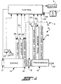
- Fig. 1 is a schematic illustration of a vehicular automated mechanical transmission system having an automated master friction clutch.
- Fig. 2 is a cross-sectional view of a typical master friction dutch of the type controlled by the clutch control and calibration of the present invention.
- Fig. 3 is a graphical illustration of one embodiment of the touch point and approach point calibration of the present invention.
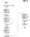
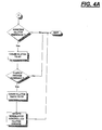
- Figs. 4 and 4A are schematic illustrations, in flow chart format, of the automated vehicular master friction clutch calibration and control of the present invention.
- Fig. 1 illustrates a semi-automatic mechanical transmission system, 10, of the type particularly advantageously utilizing the automated master clutch control and calibration method and system of the present invention.
- Semi-automated mechanical transmission system 10 comprises a multiple-speed, change-gear mechanical tranmission 12 driven by a throttle-controlled heat engine 14, such as a well-known diesel engine, through an automatically controlled master friction clutch 16.
- a throttle-controlled heat engine 14 such as a well-known diesel engine
- Semi-automated transmission systems of this general type may be seen by reference to U.S. Pats. No. 4,648,290; 4,930,081 and 5,157,607, the disclosures of which are incorporated herein by reference.
- Semi-automatic mechanical transmission system 10 is typically intended for heavy-duty vehicle use and the output of transmission 12 is output shaft 20, which is adapted for driving connection to an appropriate vehicle component, such as the differential of a drive axle, a transfer case or the like, as well known in the prior art.
- the automated system will include at least one of an engine brake 17 and/or an input shaft brake 18.
- the aforementioned drivetrain components are acted upon and/or monitored by several devices, examples of each of which are known in the prior art.
- These devices include a throttle pedal position monitor assembly 22, which senses the position or setting of the operator-controlled vehicle throttle pedal 24, a throttle control device 26, which controls the supply of fuel to the engine, an engine speed sensor 28, which senses the rotational speed of the engine, a clutch operator 30 operable to selectively engage and disengage master friction clutch 16, an input shaft speed sensor 32 for providing a signal indicative of the rotational speed of the transmission input shaft, a transmission operator 34, which is effective to shift transmission 12 and/or to provide input signals indicative of the transmission engaged ratio, and an output shaft speed sensor 36 for providing a signal indicative of the rotational speed of transmission output shaft 20.
- Semi-automated mechanical transmission system 10 may also include a selector device 1 by which the vehicle operator selects engagement of a particular gear ratio and/or a mode of transmission operation and a display 2 for providing transmission system information to the operator. Additionally, the vehicle may be provided with a manually operated clutch pedal 3 by which the vehicle operator may override the system and disengage the master clutch.
- the aforementioned devices supply information to and/or accept command output signals from a central processing unit or control 38.
- the central processing unit may include analog and/or digital or electronic calculation and logic circuitry, which is preferably microprocessor-based.
- An electrical power source (not shown) and/or a source of pressurized fluid (not shown) provides electrical and/or pneumatic and/or hydraulic power to the various sensing, operating and/or processing units.
- Drivetrain components and controls therefor of the type described above are known in the prior art and may be appreciated in greater detail by reference to U.S. Pats. No. 4,478,851; 4,019,614; 4,038,889 and 4,401,200.
- Sensors 22, 28, 32, 34, 36 and 1 and the sensors associated with operators 26, 30, 18 and 34 may be of any known type or construction for generating analog or digital signals proportional to or indicative of the parameter monitored thereby.
- operators 26, 30 and 34 may be of any known electrical, mechanical, pneumatic, hydraulic and/or electro-pneumatic type for executing operations in response to command signals from the central processing unit 38.
- the engine 14 may be electronically controlled over a data bus conforming to one of the SAE J1922, SAE J1939, ISO 11898 or similar protocols.
- a typical master friction clutch 16 of the type to be automatically controlled and calibrated by the control and calibration system of the present invention may be seen by reference to Fig. 2. It is understood, of course, that the specific construction of the clutch and actuator therefor are shown for illustrative purposes only and that the control and calibration system of the present invention is suitable for use in connection with clutches and/or operators therefor of differing structures. Further, in theory, the automated clutch and calibration method and system of the present invention is also suitable for use with so-called freestanding autoclutches associated with manually operated transmissions.
- Clutch 16 is a typical two-plate mechanical spring-applied clutch which is mounted to an engine flywheel 42. Internal lugs 44 on the inner radius of the flywheel 42 correspond to slots in the clutch pressure plate 46 and intermediate plate 48, causing these elements to rotate at engine speed. They are, however, free to move in an axial direction. Clutch-driven disks 50 are splined to the transmission input shaft 52 for rotation therewith. Clutch torque is provided by engaging springs 54 acting through levers 56 to apply pressure to pressure plate 46. This pressure squeezes the driven disks 50 and intermediate plate 48 between the pressure plate 46 and the engine flywheel 42. The magnitude of the clutch torque is proportional to this pressure.
- the force provided by the spring 54 on the pressure plate 46 may be controlled by the axial position of the throw-out bearing assembly 58.
- Throw-out bearing assembly 58 may be moved in the axial direction by a control lever 60 mounted on a shaft 59.
- the shaft 59 is mounted in a clutch housing such that pivotal movement of the clutch control lever 60 will cause an axial movement of the throw-out bearing assembly 58. In this manner, movement of the control lever 60 can vary the force on pressure plate 46 and, therefore, the available clutch torque.
- a magnetic pick-up 28A is mounted in the clutch housing and detects tooth passage of the toothed rotor 62 located on the outer radius of the engine flywheel 42 to provide a signal proportional to engine speed.
- Pivotal movement of the control lever 60 is controlled by a piston cylinder and control valve assembly 61.
- Lever 60 and assembly 61 comprise the clutch actuator 30.
- Control valve V may be as disclosed in aforementioned U.S. Pats. No. 4,081,065 and 4,361,060, comprising fine and coarse ports for both pressurizing and venting the chambers of the cylinder for modulated and rapid movement of lever 60.
- a sensor 70 for sensing clutch actuator pressure and/or a sensor 72 for sensing lever/piston position may be provided for providing input signals to controller 38.
- the automated clutch control and calibration method and system of the present invention when utilized in connection with the automated mechanical transmission system 10, comprises a portion of the central processing unit 38.
- the automated clutch control and calibration method and system of the present invention may be separate and distinct from any transmission system control devices.
- the central processing unit may utilize discreet logic components or be a programmed (by means of software and/or firmware) microprocessor. If a microprocessor is utilized, the discreet logic components/circuits, such as comparators, etc., are replaced by algorithm routines and/or subroutines, etc., as is known.
- the automated clutch control and calibration system of the present invention controls and calibrates operation of the vehicular master friction clutch 16 to engage and disengage same in accordance with current and/or stored parameters and logic rules.
- the automatic dutch control system preferably will be similar to the clutch control systems illustrated and described in aforementioned U.S. Pats. No.4,401,200; 4,081,065; 4,361,060 and/or 3,752,284.
- the master clutch in at least the start-from-stop mode of operation, the master clutch must be modulated between a fully disengaged and a fully engaged condition, or maintained at a predetermined partially engaged condition, in accordance with certain parameters which usually include at least engine speed and throttle position, to achieve an acceptably smooth start without stalling or flaring of the vehicle engine. Accordingly, in the modulated modes of clutch engagement, especially in the start-from-stop mode of operation, the clutch 16 is utilized as an essential control element of the automated mechanical transmission system.
- dutch 16 can exercise no control over the system during that portion of the engagement when it moves from the fully disengaged to the incipient engagement position, it is highly desirable to move the clutch as rapidly as possible between these positions during a modulated clutch engagement operation and then to control the degree of engagement of the clutch in a modulated manner, according to sensed, calculated and/or stored inputs and logic rules from the incipient engagement to fully engaged conditions thereof. It is known in the prior art (see aforementioned U.S. Pat. No. 4,646,891) to determine the dutch actuator 30 condition corresponding to the clutch incipient engagement condition and, in the modulated mode of operation, to switch the actuator from the rapid, unmodulated to the modulated mode of operation just prior to the occurrence of the predicted incipient engagement condition.
- the automated clutch control of the prior art is improved by rendering the automated clutch control more responsive and minimizing the possibility of overshooting the incipient engagement condition.
- This is accomplished by providing a clutch control calibration technique for determining the value of a clutch control parameter indicative of the clutch approach point, as well as a clutch actuator control parameter value indicative of the clutch incipient engagement point, wherein the clutch approach point is intermediate the fully disengaged point and the point of incipient engagement, is immediately adjacent the point of incipient engagement and preferably is a point at which the clutch will transmit torque from the engine to the transmission input shaft on an intermediate basis, provided the transmission input shaft is subject to a minimum resistance to rotation thereof.
- the master clutch upon completion of a clutch disengagement, while awaiting a command to initiate a modulated clutch engagement operation, the master clutch is moved to and dwells at the approach point. Thereafter, upon a command to engage the master clutch in a modulated manner, modulated engagement of the master clutch may commence by moving to the point of incipient engagement and then modulating the clutch to full engagement thereof without waiting for the master clutch to move from the fully disengaged condition to the point of incipient engagement and further minimizing the possibility of overshooting the point of incipient engagement.
- Points AP and TP represent values of a clutch control parameter, such as actuator pressure and/or voltage or an actuator position, as is known in the prior art.
- a clutch control parameter such as actuator pressure and/or voltage or an actuator position
- the values of the control parameters representing the approach point and the touch point may be periodically updated to account for wear and/or changes in the clutch operating temperature and the like.
- the controller 38 In operation, assuming the vehicle has been brought to a stop, upon disengaging the master dutch and shifting into the new start ratio, while awaiting the command to begin engaging the clutch for the start-from-stop operation, the controller 38 will command that the clutch 16 be moved to and dwell at the approach point AP. Thereafter, as the vehicle operator indicates his/her desire to launch the vehicle by depressing the throttle pedal, the control 38 will cause the dutch to move quickly to the touch point and then to begin a modulated, controlled engagement of vehicle master clutch.
- the automated clutch control and calibration method and system of the present invention is symbolically illustrated, in flow chart format, in Figs. 4 and 4A.
Landscapes
- Engineering & Computer Science (AREA)
- Chemical & Material Sciences (AREA)
- Combustion & Propulsion (AREA)
- Mechanical Engineering (AREA)
- Transportation (AREA)
- General Engineering & Computer Science (AREA)
- Fluid Mechanics (AREA)
- Physics & Mathematics (AREA)
- Automation & Control Theory (AREA)
- Hydraulic Clutches, Magnetic Clutches, Fluid Clutches, And Fluid Joints (AREA)
- Mechanical Operated Clutches (AREA)
- Sewing Machines And Sewing (AREA)
- Control Of Driving Devices And Active Controlling Of Vehicle (AREA)
Abstract
Description
- The present invention relates to the control and calibration of an automated master friction clutch as utilized in an at least partially automated mechanical transmission system.
- Vehicular automated mechanical transmission systems comprising a multiple-speed mechanical transmission drivingly connected to a fuel-controlled engine by means of an automatically actuated vehicle master friction clutch are well known in the prior art, as may be seen by reference to U.S. Pats. No.4,081,065; 4,361,060; 4,527,447; 4,638,898; 4,648,290; 4,714,144; 4,873,637; 5,275,267; 5,293,316; 5,314,050 and 5,316,116.
- To improve the controllability and responsiveness of the prior art master clutch control systems, it was known to determine a clutch control parameter value, such as a clutch actuator position, which corresponded to the "touch point" or "point of incipient engagement" of the clutch, i.e., that point or position during engagement of the master clutch at which the master dutch just began to transmit torque. The clutch touch point was determined or calibrated during a system startup routine and was thereafter subject to updating during ongoing vehicle operations.
- During a controlled master clutch engagement, the master clutch was moved rapidly from its disengaged position to the touch point/point of incipient engagement, and then was further engaged in a controlled, modulated manner according to the applicable clutch control logic. Examples of such clutch control logic may be seen by reference to U.S. Pats. No. 4,646,891; 4,899,858 and 5,337,874, which discloses the features of the preamble of claim 1 and 4.
- According to the present invention, the responsiveness of vehicular automated master clutch control is improved, as compared to the prior art, by defining, during calibration operations, a control parameter value corresponding to an "approach point" as well as to the touch point, wherein the approach point is a point intermediate full disengagement and the touch point, preferably almost to the touch point. After full disengagement of the master clutch, when a required clutch engagement is expected, the clutch is moved to and dwells at the approach point, awaiting initiation of clutch engagement. The clutch may then be moved even more quickly and with less risk of overshoot to the touch point for commencement of controlled, modulated further engagement.
- By way of example, to illustrate both a calibration technique and the relative values of control parameters corresponding to master clutch touch point and master dutch approach point, assuming some type of input shaft brake/upshift brake, with the vehicle at rest, the control parameter value corresponding to approach point is determined by slowly moving from full disengagement toward engagement, with the input shaft brake off, and sensing for initial rotation of the input shaft, while the control parameter value corresponding to touch point is determined in the same manner, except that the input shaft brake is active so that input shaft initial increased rotational speed is indicative of at least minimal clutch torque transfer.
- Accordingly, it is an object of the present invention to provide a new and improved control and calibration method and system to improve responsiveness of automated vehicular master clutches. This and other objects and advantages of the present invention will become apparent from a reading of the detailed description of the preferred embodiment taken in connection with the drawings.
- Fig. 1 is a schematic illustration of a vehicular automated mechanical transmission system having an automated master friction clutch.
- Fig. 2 is a cross-sectional view of a typical master friction dutch of the type controlled by the clutch control and calibration of the present invention.
- Fig. 3 is a graphical illustration of one embodiment of the touch point and approach point calibration of the present invention.
- Figs. 4 and 4A are schematic illustrations, in flow chart format, of the automated vehicular master friction clutch calibration and control of the present invention.
- Fig. 1 illustrates a semi-automatic mechanical transmission system, 10, of the type particularly advantageously utilizing the automated master clutch control and calibration method and system of the present invention. Semi-automated mechanical transmission system 10 comprises a multiple-speed, change-gear
mechanical tranmission 12 driven by a throttle-controlledheat engine 14, such as a well-known diesel engine, through an automatically controlledmaster friction clutch 16. Semi-automated transmission systems of this general type may be seen by reference to U.S. Pats. No. 4,648,290; 4,930,081 and 5,157,607, the disclosures of which are incorporated herein by reference. It is understood, however, that the automated clutch control and calibration method and system of the present invention is also applicable to other types of fully or partially automated mechanical transmission systems, such as, for example, those illustrated in U.S. Pats. No. 4,361,060; 4,860,861; 5,261,288 and 5,305,213. - Semi-automatic mechanical transmission system 10 is typically intended for heavy-duty vehicle use and the output of
transmission 12 isoutput shaft 20, which is adapted for driving connection to an appropriate vehicle component, such as the differential of a drive axle, a transfer case or the like, as well known in the prior art. Preferably, the automated system will include at least one of anengine brake 17 and/or aninput shaft brake 18. The aforementioned drivetrain components are acted upon and/or monitored by several devices, examples of each of which are known in the prior art. These devices include a throttle pedalposition monitor assembly 22, which senses the position or setting of the operator-controlledvehicle throttle pedal 24, athrottle control device 26, which controls the supply of fuel to the engine, anengine speed sensor 28, which senses the rotational speed of the engine, aclutch operator 30 operable to selectively engage and disengagemaster friction clutch 16, an inputshaft speed sensor 32 for providing a signal indicative of the rotational speed of the transmission input shaft, a transmission operator 34, which is effective to shifttransmission 12 and/or to provide input signals indicative of the transmission engaged ratio, and an outputshaft speed sensor 36 for providing a signal indicative of the rotational speed oftransmission output shaft 20. Semi-automated mechanical transmission system 10 may also include a selector device 1 by which the vehicle operator selects engagement of a particular gear ratio and/or a mode of transmission operation and adisplay 2 for providing transmission system information to the operator. Additionally, the vehicle may be provided with a manually operated clutch pedal 3 by which the vehicle operator may override the system and disengage the master clutch. - The aforementioned devices supply information to and/or accept command output signals from a central processing unit or
control 38. The central processing unit may include analog and/or digital or electronic calculation and logic circuitry, which is preferably microprocessor-based. An electrical power source (not shown) and/or a source of pressurized fluid (not shown) provides electrical and/or pneumatic and/or hydraulic power to the various sensing, operating and/or processing units. Drivetrain components and controls therefor of the type described above are known in the prior art and may be appreciated in greater detail by reference to U.S. Pats. No. 4,478,851; 4,019,614; 4,038,889 and 4,401,200. -
Sensors operators operators central processing unit 38. Theengine 14 may be electronically controlled over a data bus conforming to one of the SAE J1922, SAE J1939, ISO 11898 or similar protocols. - A typical
master friction clutch 16 of the type to be automatically controlled and calibrated by the control and calibration system of the present invention may be seen by reference to Fig. 2. It is understood, of course, that the specific construction of the clutch and actuator therefor are shown for illustrative purposes only and that the control and calibration system of the present invention is suitable for use in connection with clutches and/or operators therefor of differing structures. Further, in theory, the automated clutch and calibration method and system of the present invention is also suitable for use with so-called freestanding autoclutches associated with manually operated transmissions. -
Clutch 16, illustrated, is a typical two-plate mechanical spring-applied clutch which is mounted to anengine flywheel 42.Internal lugs 44 on the inner radius of theflywheel 42 correspond to slots in theclutch pressure plate 46 andintermediate plate 48, causing these elements to rotate at engine speed. They are, however, free to move in an axial direction. Clutch-drivendisks 50 are splined to thetransmission input shaft 52 for rotation therewith. Clutch torque is provided by engagingsprings 54 acting throughlevers 56 to apply pressure topressure plate 46. This pressure squeezes the drivendisks 50 andintermediate plate 48 between thepressure plate 46 and theengine flywheel 42. The magnitude of the clutch torque is proportional to this pressure. - The force provided by the
spring 54 on thepressure plate 46 may be controlled by the axial position of the throw-outbearing assembly 58. Throw-out bearingassembly 58 may be moved in the axial direction by acontrol lever 60 mounted on ashaft 59. Theshaft 59 is mounted in a clutch housing such that pivotal movement of theclutch control lever 60 will cause an axial movement of the throw-outbearing assembly 58. In this manner, movement of thecontrol lever 60 can vary the force onpressure plate 46 and, therefore, the available clutch torque. A magnetic pick-up 28A is mounted in the clutch housing and detects tooth passage of thetoothed rotor 62 located on the outer radius of theengine flywheel 42 to provide a signal proportional to engine speed. - Pivotal movement of the
control lever 60 is controlled by a piston cylinder andcontrol valve assembly 61.Lever 60 andassembly 61 comprise theclutch actuator 30. Control valve V may be as disclosed in aforementioned U.S. Pats. No. 4,081,065 and 4,361,060, comprising fine and coarse ports for both pressurizing and venting the chambers of the cylinder for modulated and rapid movement oflever 60. A sensor 70 for sensing clutch actuator pressure and/or asensor 72 for sensing lever/piston position may be provided for providing input signals to controller 38. - The automated clutch control and calibration method and system of the present invention, when utilized in connection with the automated mechanical transmission system 10, comprises a portion of the
central processing unit 38. As indicated above, the automated clutch control and calibration method and system of the present invention may be separate and distinct from any transmission system control devices. The central processing unit may utilize discreet logic components or be a programmed (by means of software and/or firmware) microprocessor. If a microprocessor is utilized, the discreet logic components/circuits, such as comparators, etc., are replaced by algorithm routines and/or subroutines, etc., as is known. - The automated clutch control and calibration system of the present invention controls and calibrates operation of the vehicular master friction clutch 16 to engage and disengage same in accordance with current and/or stored parameters and logic rules. The automatic dutch control system preferably will be similar to the clutch control systems illustrated and described in aforementioned U.S. Pats. No.4,401,200; 4,081,065; 4,361,060 and/or 3,752,284.
- Typically, in at least the start-from-stop mode of operation, the master clutch must be modulated between a fully disengaged and a fully engaged condition, or maintained at a predetermined partially engaged condition, in accordance with certain parameters which usually include at least engine speed and throttle position, to achieve an acceptably smooth start without stalling or flaring of the vehicle engine. Accordingly, in the modulated modes of clutch engagement, especially in the start-from-stop mode of operation, the clutch 16 is utilized as an essential control element of the automated mechanical transmission system. As the dutch 16 can exercise no control over the system during that portion of the engagement when it moves from the fully disengaged to the incipient engagement position, it is highly desirable to move the clutch as rapidly as possible between these positions during a modulated clutch engagement operation and then to control the degree of engagement of the clutch in a modulated manner, according to sensed, calculated and/or stored inputs and logic rules from the incipient engagement to fully engaged conditions thereof. It is known in the prior art (see aforementioned U.S. Pat. No. 4,646,891) to determine the
dutch actuator 30 condition corresponding to the clutch incipient engagement condition and, in the modulated mode of operation, to switch the actuator from the rapid, unmodulated to the modulated mode of operation just prior to the occurrence of the predicted incipient engagement condition. - According to the present invention, the automated clutch control of the prior art is improved by rendering the automated clutch control more responsive and minimizing the possibility of overshooting the incipient engagement condition. This is accomplished by providing a clutch control calibration technique for determining the value of a clutch control parameter indicative of the clutch approach point, as well as a clutch actuator control parameter value indicative of the clutch incipient engagement point, wherein the clutch approach point is intermediate the fully disengaged point and the point of incipient engagement, is immediately adjacent the point of incipient engagement and preferably is a point at which the clutch will transmit torque from the engine to the transmission input shaft on an intermediate basis, provided the transmission input shaft is subject to a minimum resistance to rotation thereof. According to the clutch control of the present invention, upon completion of a clutch disengagement, while awaiting a command to initiate a modulated clutch engagement operation, the master clutch is moved to and dwells at the approach point. Thereafter, upon a command to engage the master clutch in a modulated manner, modulated engagement of the master clutch may commence by moving to the point of incipient engagement and then modulating the clutch to full engagement thereof without waiting for the master clutch to move from the fully disengaged condition to the point of incipient engagement and further minimizing the possibility of overshooting the point of incipient engagement.
- An example of the clutch calibration technique of the present invention as utilized for semi-automated transmission system 10 may be seen by reference to Fig. 3. With the vehicle stationary (OS = 0),
transmission 12 in neutral (GR = N), theengine 14 at idle and the input shaft brake disengaged, theclutch actuator 30 is caused to slowly move the clutch from the fully disengaged condition toward the engaged condition thereof while input shaft rotational speed (IS) is monitored. As is represented byline 76, at a certain point, the input shaft will begin to move, and this is taken as the approach point (indicated as "AP" in Fig. 3). The same procedure is repeated, except with the input shaft brake applied, as indicated byline 78, and the point at which input shaft speed is sensed is taken as the touch point or point of incipient engagement (indicated as point "TP" in Fig. 3). Points AP and TP represent values of a clutch control parameter, such as actuator pressure and/or voltage or an actuator position, as is known in the prior art. As is also known in the prior art (see, for example, aforementioned U.S. Pat. No. 5,337,874), the values of the control parameters representing the approach point and the touch point may be periodically updated to account for wear and/or changes in the clutch operating temperature and the like. - In operation, assuming the vehicle has been brought to a stop, upon disengaging the master dutch and shifting into the new start ratio, while awaiting the command to begin engaging the clutch for the start-from-stop operation, the
controller 38 will command that the clutch 16 be moved to and dwell at the approach point AP. Thereafter, as the vehicle operator indicates his/her desire to launch the vehicle by depressing the throttle pedal, thecontrol 38 will cause the dutch to move quickly to the touch point and then to begin a modulated, controlled engagement of vehicle master clutch. The automated clutch control and calibration method and system of the present invention is symbolically illustrated, in flow chart format, in Figs. 4 and 4A.
Claims (5)
- A method for controlling an automated vehicular master friction clutch (16) drivingly interposed between an engine (14) and an input shaft (52) of a multiple-speed transmission (12), said clutch having a fully disengaged condition position, a touch point condition position (TP) at which the clutch will just begin to transmit torque, and an approach point condition position (AP) intermediate said fully disengaged condition position and touch point condition position, said method characterized by:(a) determining a value (AP) of said clutch control parameter indicative of said clutch being at the approach point condition thereof; and(b) after disengaging said clutch and while awaiting a clutch engagement command, causing said clutch to assume and remain in the approach point condition thereof.
- The method of claim 1 wherein said transmission has a controllable input shaft retarding device (18) associated therewith; said value (AP) being determined while said device is inactive.
- The method of claim 1 wherein said clutch is associated with a vehicular automated mechanical transmission system, said transmission has a controllable input shaft retarding device associated therewith and said system further comprises an electronic controller (38) for receiving input signals including a signal indicative of rotational speed of said input shaft (IS) and for processing same according to predetermined logic rules to issue command output signals to at least an engine fuel control (26), a clutch operator (30), said input shaft retarding device and a transmission operator (34);
step (a) comprising (i) causing the engine retarding device (18) to be released, (ii) causing the engine to idle, (iii) causing the transmission to be in neutral, (iv) causing the clutch to be slowly engaged while monitoring current values of said clutch control parameter and input shaft rotational speed and (v) upon sensing initial increased rotation of said input shaft, setting said value equal to the then current value of said clutch control parameter. - A control system for controlling an automated vehicular master friction clutch (16) drivingly interposed between an engine (14) and an input shaft (52) of a multiple-speed transmission (12), said clutch having an approach point condition intermediate between a fully disengaged condition and a touch point condition (TP), at which the clutch will just begin to transmit torque, said control system characterized by:means for determining a value (AP) of a clutch control parameter indicative of said clutch being at the approach point condition thereof; andmeans effective, after disengaging said clutch and while awaiting a clutch engagement command, for causing said clutch to assume and remain in the approach point condition thereof.
- The control system of claim 4 wherein said clutch is associated with a vehicular automated mechanical transmission system, said transmission has a controllable input shaft retarding device (18) associated therewith and said system further comprises an electronic controller (38) for receiving input signals including a signal indicative of rotational speed of said input shaft (IS) and for processing same according to predetermined logic rules to issue command output signals to at least an engine fuel control (26), a clutch operator (30), said input shaft retarding device (18) and a transmission operator (34);
said approad point determining means comprising means for (i) causing the engine retarding device to be released, (ii) causing the engine to idle, (iii) causing the transmission to be in neutral, (iv) causing the clutch to be slowly engaged while monitoring current values of said clutch control parameter and input shaft rotational speed and (v) upon sensing initial increased rotation of said input shaft, setting said value equal to the then current value of said clutch control parameter.
Applications Claiming Priority (2)
| Application Number | Priority Date | Filing Date | Title |
|---|---|---|---|
| GB9421350A GB9421350D0 (en) | 1994-10-24 | 1994-10-24 | Automated clutch control and calibration |
| GB9421350 | 1994-10-24 |
Publications (3)
| Publication Number | Publication Date |
|---|---|
| EP0709246A2 EP0709246A2 (en) | 1996-05-01 |
| EP0709246A3 EP0709246A3 (en) | 1998-03-18 |
| EP0709246B1 true EP0709246B1 (en) | 2001-07-25 |
Family
ID=10763264
Family Applications (1)
| Application Number | Title | Priority Date | Filing Date |
|---|---|---|---|
| EP95307333A Expired - Lifetime EP0709246B1 (en) | 1994-10-24 | 1995-10-16 | Automated clutch control and calibration |
Country Status (10)
| Country | Link |
|---|---|
| US (1) | US5624350A (en) |
| EP (1) | EP0709246B1 (en) |
| JP (1) | JPH08210381A (en) |
| KR (1) | KR100285405B1 (en) |
| AT (1) | ATE203470T1 (en) |
| BR (1) | BR9504866A (en) |
| CA (1) | CA2159663C (en) |
| DE (1) | DE69521866T2 (en) |
| ES (1) | ES2160672T3 (en) |
| GB (1) | GB9421350D0 (en) |
Cited By (1)
| Publication number | Priority date | Publication date | Assignee | Title |
|---|---|---|---|---|
| EP2147841A2 (en) | 2008-07-24 | 2010-01-27 | ZF Friedrichshafen AG | Method for controlling an automated drive |
Families Citing this family (42)
| Publication number | Priority date | Publication date | Assignee | Title |
|---|---|---|---|---|
| NO314174B1 (en) * | 1995-12-18 | 2003-02-10 | Luk Getriebe Systeme Gmbh | Motor vehicles |
| US6001044A (en) * | 1995-12-18 | 1999-12-14 | Luk Getriebe-Systeme Gmbh | Motor vehicle |
| DE19630014C2 (en) * | 1996-07-25 | 1998-05-20 | Daimler Benz Ag | Automatically controlled clutch |
| DE19712871A1 (en) * | 1997-03-27 | 1998-10-01 | Bosch Gmbh Robert | Coupling system |
| US6309325B1 (en) * | 1997-04-17 | 2001-10-30 | Transmission Tsp, S.A. De C.V. | Method and apparatus for operating a clutch in an automated mechanical transmission |
| US6227999B1 (en) * | 1997-07-09 | 2001-05-08 | Transmisiones Tsp, S.A. De C.V. | Method and apparatus for operating a clutch in an automated mechanical transmission |
| US5993350A (en) * | 1997-12-01 | 1999-11-30 | Lawrie; Robert E. | Automated manual transmission clutch controller |
| JPH11247890A (en) * | 1998-02-27 | 1999-09-14 | Isuzu Motors Ltd | Method of specifying half-clutch stroke value and abnormality diagnosis method |
| US6050379A (en) * | 1998-07-10 | 2000-04-18 | Chrysler Corporation | Algorithm for electro-mechanical clutch actuator |
| US6085606A (en) * | 1998-11-03 | 2000-07-11 | Eaton Corporation | Mechanical transmission with reduced ratio steps in upper transmission ratios |
| US5980428A (en) * | 1998-11-13 | 1999-11-09 | Eaton Corporation | Vehicle launch automated master clutch control |
| US6022295A (en) * | 1998-11-12 | 2000-02-08 | Eaton Corporation | Touch point identification for vehicle master clutch |
| US6071211A (en) * | 1998-11-18 | 2000-06-06 | Eaton Corporation | Idle drive torque control for automated vehicle master clutch |
| US6332257B1 (en) * | 1999-04-30 | 2001-12-25 | Chrysler Corporation | Method of converting an existing vehicle powertrain to a hybrid powertrain system |
| SE517743C2 (en) * | 1999-09-03 | 2002-07-09 | Volvo Lastvagnar Ab | Drive unit for a motor vehicle and ways of identifying the traction position of an automated clutch included in the drive unit |
| GB2361980A (en) * | 2000-05-05 | 2001-11-07 | Eaton Corp | Dry clutch control system using idle drive torque so as to provide vehicle crawl speed |
| DE10032366A1 (en) * | 2000-07-04 | 2002-01-17 | Mannesmann Sachs Ag | Determining predefined actuation setting for automated frictional coupling involves correcting transferred coupling torque depending on coupling torque/actuation point relationship |
| US6494810B1 (en) | 2001-05-30 | 2002-12-17 | Eaton Corporation | Clutch calibration and control |
| WO2002101258A2 (en) * | 2001-06-13 | 2002-12-19 | Luk Lamellen Und Kupplungsbau Beteiligungs Kg | Clutch actuation device and methods for determining clutch parameters |
| DE10351906A1 (en) * | 2002-11-11 | 2004-05-27 | Luk Lamellen Und Kupplungsbau Beteiligungs Kg | Clutch engaging point method for adapting a clutch's point of engagement in an automatic gearbox presets measuring torque on the clutch as a clutch torque |
| US6916271B2 (en) * | 2003-08-07 | 2005-07-12 | Caterpillar Inc | Method and apparatus for calibrating a marine trolling valve |
| US20050109141A1 (en) * | 2003-11-25 | 2005-05-26 | Devore James H. | Automated mechanical transmission system |
| SE525163C2 (en) * | 2004-01-14 | 2004-12-14 | Volvo Lastvagnar Ab | Drive units for motor vehicles and method for determining the characteristics of the drive unit clutch |
| US7048106B2 (en) * | 2004-03-26 | 2006-05-23 | Cnh America Llc | Power take-off control system and method |
| US7139653B2 (en) * | 2004-07-15 | 2006-11-21 | International Truck Intellectual Property Company, Llc | Common control interface for diverse automated manual transmissions |
| EP1630628B1 (en) * | 2004-08-24 | 2009-09-09 | LuK Lamellen und Kupplungsbau Beteiligungs KG | Method for reducing position oscillations of an actuator controlled by a position controller of an automatic clutch |
| DE102007002343A1 (en) | 2007-01-16 | 2008-07-17 | Zf Friedrichshafen Ag | Method for dynamically determining a clutch resting point |
| US7731630B2 (en) * | 2007-02-08 | 2010-06-08 | Caterpillar Inc. | Calibration system for hydraulic transmission |
| DE102008023360A1 (en) * | 2007-05-31 | 2008-12-04 | Luk Lamellen Und Kupplungsbau Beteiligungs Kg | Method for plausibility checking of the position of the clutch actuator of a clutch, method for determining the touch point of a clutch and device for carrying out the method |
| DE102007036405B4 (en) * | 2007-07-27 | 2009-04-23 | Getrag Getriebe- Und Zahnradfabrik Hermann Hagenmeyer Gmbh & Cie Kg | Method for switching a stepped gear of a motor vehicle as a function of the drive shaft speed |
| DE102008000770A1 (en) * | 2008-03-19 | 2009-09-24 | Robert Bosch Gmbh | Method and device for closing a clutch |
| US8738256B2 (en) * | 2008-07-01 | 2014-05-27 | Eaton Corporation | Automatic calibration of the torque transfer touch point in an electrically actuated clutch in a hybrid vehicle |
| US8577570B2 (en) * | 2009-04-17 | 2013-11-05 | Honda Motor Co., Ltd. | Touch point calibration method for a motor vehicle |
| DE102010024941A1 (en) * | 2009-07-16 | 2011-01-20 | Luk Lamellen Und Kupplungsbau Beteiligungs Kg | Kupplungstastpunkte |
| US20110098897A1 (en) * | 2009-10-22 | 2011-04-28 | Matthew Richard Busdiecker | Method of identifying a release bearing touch point in a clutch system |
| SE535679C2 (en) * | 2011-03-14 | 2012-11-06 | Scania Cv Ab | Method and system for determining a contact point for a connection |
| KR101406422B1 (en) * | 2012-11-09 | 2014-06-13 | 기아자동차주식회사 | Touch point searching method for clutch |
| US9115772B2 (en) | 2013-09-30 | 2015-08-25 | Cnh Industrial America Llc | System and method for automatically calibrating the clutches within a transmission of a work vehicle |
| US9759275B2 (en) * | 2014-12-10 | 2017-09-12 | Ford Global Technologies, Llc | Electronic control of manual transmission clutch |
| US10082184B2 (en) | 2015-03-02 | 2018-09-25 | Rolls-Royce Corporation | System and method for eliminating adverse clutch vibratory responses |
| CN109469689B (en) * | 2018-12-26 | 2023-10-13 | 黄淮学院 | Stepping motor type automobile clutch |
| KR102333632B1 (en) * | 2020-01-14 | 2021-12-01 | 국방과학연구소 | Vehicle Control Apparatus and Method |
Citations (2)
| Publication number | Priority date | Publication date | Assignee | Title |
|---|---|---|---|---|
| US4646891A (en) * | 1985-01-31 | 1987-03-03 | Eaton Corporation | Automatic clutch control |
| US5337874A (en) * | 1993-03-19 | 1994-08-16 | Eaton Corporation | Method/system for determining clutch touch point |
Family Cites Families (30)
| Publication number | Priority date | Publication date | Assignee | Title |
|---|---|---|---|---|
| US3089572A (en) * | 1961-06-07 | 1963-05-14 | Cincinnati Milling Machine Co | Machine tool drive system control mechanism |
| GB1342623A (en) | 1971-02-23 | 1974-01-03 | Ford Motor Co | Friction clutch control system |
| DE2456509C3 (en) | 1974-11-29 | 1978-11-02 | Frieseke & Hoepfner Gmbh, 8520 Erlangen | Electrical control device for the clutch actuation of a clutch of a motor vehicle, in particular a truck, which is held engaged by spring force |
| US4038889A (en) | 1975-05-14 | 1977-08-02 | Fmc Corporation | Electronic transmission controller |
| US4081065A (en) * | 1976-12-23 | 1978-03-28 | Smyth Robert Ralston | Controlled power clutch |
| US4361060A (en) * | 1978-01-24 | 1982-11-30 | Smyth Robert Ralston | Mechanical automatic transmission |
| DE2946497A1 (en) | 1979-11-17 | 1981-06-11 | Volkswagenwerk Ag, 3180 Wolfsburg | DEVICE FOR AUTOMATIC CLUTCH ACTUATION |
| US4478851A (en) | 1980-02-12 | 1984-10-23 | Synthelabo | Benzylidene derivatives and compositions containing them |
| US4527447A (en) | 1982-12-06 | 1985-07-09 | Eaton Corporation | Automatic mechanical transmission system |
| GB8418749D0 (en) | 1984-07-23 | 1984-08-30 | Eaton Ltd | Semi-automatic transmission control |
| US4930081A (en) | 1984-07-23 | 1990-05-29 | Eaton Corporation | Semi-automatic mechanical transmission control and control method |
| US4638898A (en) * | 1985-12-19 | 1987-01-27 | Eaton Corporation | Clutch control system and clutch assembly using same |
| US4714144A (en) * | 1986-04-18 | 1987-12-22 | Eaton Corporation | Method for controlling AMT system start from stop operation |
| US4860861A (en) | 1987-09-17 | 1989-08-29 | Eaton Corporation | Torque converter lock-up and disconnect clutch structure |
| DE3737899A1 (en) * | 1987-11-07 | 1989-08-03 | Sachs Systemtechnik Gmbh | DEVICE FOR AUTOMATICALLY OPERATING A FRICTION CLUTCH |
| US4873637A (en) * | 1988-02-10 | 1989-10-10 | Eaton Corporation | Control for vehicle start from stop operation |
| US4874070A (en) * | 1988-02-10 | 1989-10-17 | Eaton Corporation | Control for AMT system start from stop operation |
| US4899858A (en) * | 1989-03-02 | 1990-02-13 | Eaton Corporation | Method and control system for updating of control parameter value indicative of master clutch point of incipient engagement |
| GB9001273D0 (en) | 1990-01-19 | 1990-03-21 | Eaton Corp | Control and method for controlling amt system including in-gear fault detection & tolerance |
| US5065891A (en) * | 1990-07-19 | 1991-11-19 | Casey Robert G | Removable or fixed inner ring device for trash receptacle liners |
| US5056639A (en) * | 1990-09-10 | 1991-10-15 | Zahnradfabrik Friedrichshafen Ag | Device and method for the control of an automatic vehicle clutch |
| US5305213A (en) | 1991-05-09 | 1994-04-19 | Eaton Corporation | Driveline torque limit control strategy-using SAE J1922 type engine control |
| US5293316A (en) | 1991-10-07 | 1994-03-08 | Eaton Corporation | Closed loop launch and creep control for automatic clutch |
| US5275267A (en) * | 1991-10-07 | 1994-01-04 | Eaton Corporation | Closed loop launch and creep control for automatic clutch with robust algorithm |
| US5337868A (en) * | 1992-01-02 | 1994-08-16 | Eaton Corporation | Touch point identification for automatic clutch controller |
| JP3401268B2 (en) * | 1992-03-06 | 2003-04-28 | ジヤトコ株式会社 | Automatic transmission clutch control method and device |
| US5314050A (en) * | 1992-12-09 | 1994-05-24 | Eaton Corporation | Clutch mode control logic |
| US5316116A (en) * | 1992-12-09 | 1994-05-31 | Eaton Corporation | Engine control method for use with automatic clutch control |
| US5261288A (en) | 1992-12-18 | 1993-11-16 | Eaton Corporation | Enhanced missed shift from neutral recovery for automated or semi-automated mechanical transmission system |
| US5393274A (en) * | 1993-07-19 | 1995-02-28 | Eaton Corporation | Touch point identification algorithm for automatic clutch controller |
-
1994
- 1994-10-24 GB GB9421350A patent/GB9421350D0/en active Pending
-
1995
- 1995-08-28 US US08/520,360 patent/US5624350A/en not_active Expired - Lifetime
- 1995-10-02 CA CA002159663A patent/CA2159663C/en not_active Expired - Fee Related
- 1995-10-16 ES ES95307333T patent/ES2160672T3/en not_active Expired - Lifetime
- 1995-10-16 EP EP95307333A patent/EP0709246B1/en not_active Expired - Lifetime
- 1995-10-16 AT AT95307333T patent/ATE203470T1/en not_active IP Right Cessation
- 1995-10-16 DE DE69521866T patent/DE69521866T2/en not_active Expired - Lifetime
- 1995-10-17 JP JP7293573A patent/JPH08210381A/en active Pending
- 1995-10-20 BR BR9504866A patent/BR9504866A/en not_active IP Right Cessation
- 1995-10-24 KR KR1019950036808A patent/KR100285405B1/en not_active Expired - Fee Related
Patent Citations (2)
| Publication number | Priority date | Publication date | Assignee | Title |
|---|---|---|---|---|
| US4646891A (en) * | 1985-01-31 | 1987-03-03 | Eaton Corporation | Automatic clutch control |
| US5337874A (en) * | 1993-03-19 | 1994-08-16 | Eaton Corporation | Method/system for determining clutch touch point |
Cited By (2)
| Publication number | Priority date | Publication date | Assignee | Title |
|---|---|---|---|---|
| EP2147841A2 (en) | 2008-07-24 | 2010-01-27 | ZF Friedrichshafen AG | Method for controlling an automated drive |
| DE102008040678A1 (en) | 2008-07-24 | 2010-01-28 | Zf Friedrichshafen Ag | Method for controlling an automated transmission |
Also Published As
| Publication number | Publication date |
|---|---|
| DE69521866D1 (en) | 2001-08-30 |
| CA2159663C (en) | 2001-08-14 |
| KR100285405B1 (en) | 2001-12-17 |
| KR960014695A (en) | 1996-05-22 |
| US5624350A (en) | 1997-04-29 |
| EP0709246A3 (en) | 1998-03-18 |
| ES2160672T3 (en) | 2001-11-16 |
| GB9421350D0 (en) | 1994-12-07 |
| JPH08210381A (en) | 1996-08-20 |
| BR9504866A (en) | 1997-09-02 |
| CA2159663A1 (en) | 1996-04-25 |
| ATE203470T1 (en) | 2001-08-15 |
| EP0709246A2 (en) | 1996-05-01 |
| DE69521866T2 (en) | 2002-04-11 |
Similar Documents
| Publication | Publication Date | Title |
|---|---|---|
| US5624350A (en) | Automated clutch control and calibration | |
| US4899858A (en) | Method and control system for updating of control parameter value indicative of master clutch point of incipient engagement | |
| US6602161B2 (en) | Arrangement for operating the clutch in the power train of a motor vehicle | |
| US4646891A (en) | Automatic clutch control | |
| EP0686789B1 (en) | Method for decreasing ratio changing time in powertrain systems | |
| EP1000794A2 (en) | Vehicle launch automated master clutch control | |
| US5529548A (en) | Vehicle launch engine fuel control | |
| US6364813B1 (en) | Method and apparatus for operating a clutch in an automated mechanical transmission | |
| US6227999B1 (en) | Method and apparatus for operating a clutch in an automated mechanical transmission | |
| US6223874B1 (en) | Apparatus for operating a clutch in an automated mechanical transmission | |
| US6309325B1 (en) | Method and apparatus for operating a clutch in an automated mechanical transmission | |
| US6319173B1 (en) | Method and apparatus for operating a clutch in an automated mechanical transmission | |
| US6059691A (en) | Method and apparatus for operating a clutch in an automated mechanical transmission | |
| US6206803B1 (en) | Method and apparatus for operating a clutch in an automated mechanical transmission | |
| US6213916B1 (en) | Apparatus for operating a clutch in an automated mechanical transmission | |
| US6047800A (en) | Automatic clutch | |
| US6397998B1 (en) | Apparatus for operating a clutch in an automated mechanical transmission | |
| US20020193203A1 (en) | Method and apparatus for operating a clutch in an automated mechanical transmission | |
| WO1998046907A2 (en) | Method and apparatus for operating a clutch in an automated mechanical transmission |
Legal Events
| Date | Code | Title | Description |
|---|---|---|---|
| PUAI | Public reference made under article 153(3) epc to a published international application that has entered the european phase |
Free format text: ORIGINAL CODE: 0009012 |
|
| AK | Designated contracting states |
Kind code of ref document: A2 Designated state(s): AT DE ES FR GB IT NL SE |
|
| PUAL | Search report despatched |
Free format text: ORIGINAL CODE: 0009013 |
|
| AK | Designated contracting states |
Kind code of ref document: A3 Designated state(s): AT DE ES FR GB IT NL SE |
|
| 17P | Request for examination filed |
Effective date: 19980618 |
|
| 17Q | First examination report despatched |
Effective date: 19991207 |
|
| GRAG | Despatch of communication of intention to grant |
Free format text: ORIGINAL CODE: EPIDOS AGRA |
|
| RIC1 | Information provided on ipc code assigned before grant |
Free format text: 7B 60K 41/02 A, 7F 16D 48/06 B |
|
| GRAG | Despatch of communication of intention to grant |
Free format text: ORIGINAL CODE: EPIDOS AGRA |
|
| GRAH | Despatch of communication of intention to grant a patent |
Free format text: ORIGINAL CODE: EPIDOS IGRA |
|
| GRAH | Despatch of communication of intention to grant a patent |
Free format text: ORIGINAL CODE: EPIDOS IGRA |
|
| GRAH | Despatch of communication of intention to grant a patent |
Free format text: ORIGINAL CODE: EPIDOS IGRA |
|
| GRAH | Despatch of communication of intention to grant a patent |
Free format text: ORIGINAL CODE: EPIDOS IGRA |
|
| GRAA | (expected) grant |
Free format text: ORIGINAL CODE: 0009210 |
|
| AK | Designated contracting states |
Kind code of ref document: B1 Designated state(s): AT DE ES FR GB IT NL SE |
|
| REF | Corresponds to: |
Ref document number: 203470 Country of ref document: AT Date of ref document: 20010815 Kind code of ref document: T |
|
| REF | Corresponds to: |
Ref document number: 69521866 Country of ref document: DE Date of ref document: 20010830 |
|
| ITF | It: translation for a ep patent filed | ||
| REG | Reference to a national code |
Ref country code: ES Ref legal event code: FG2A Ref document number: 2160672 Country of ref document: ES Kind code of ref document: T3 |
|
| ET | Fr: translation filed | ||
| REG | Reference to a national code |
Ref country code: GB Ref legal event code: IF02 |
|
| PLBE | No opposition filed within time limit |
Free format text: ORIGINAL CODE: 0009261 |
|
| STAA | Information on the status of an ep patent application or granted ep patent |
Free format text: STATUS: NO OPPOSITION FILED WITHIN TIME LIMIT |
|
| 26N | No opposition filed | ||
| PGFP | Annual fee paid to national office [announced via postgrant information from national office to epo] |
Ref country code: AT Payment date: 20040914 Year of fee payment: 10 |
|
| PGFP | Annual fee paid to national office [announced via postgrant information from national office to epo] |
Ref country code: NL Payment date: 20040921 Year of fee payment: 10 |
|
| PGFP | Annual fee paid to national office [announced via postgrant information from national office to epo] |
Ref country code: FR Payment date: 20041004 Year of fee payment: 10 |
|
| PGFP | Annual fee paid to national office [announced via postgrant information from national office to epo] |
Ref country code: ES Payment date: 20041026 Year of fee payment: 10 |
|
| PG25 | Lapsed in a contracting state [announced via postgrant information from national office to epo] |
Ref country code: IT Free format text: LAPSE BECAUSE OF NON-PAYMENT OF DUE FEES;WARNING: LAPSES OF ITALIAN PATENTS WITH EFFECTIVE DATE BEFORE 2007 MAY HAVE OCCURRED AT ANY TIME BEFORE 2007. THE CORRECT EFFECTIVE DATE MAY BE DIFFERENT FROM THE ONE RECORDED. Effective date: 20051016 Ref country code: AT Free format text: LAPSE BECAUSE OF NON-PAYMENT OF DUE FEES Effective date: 20051016 |
|
| PG25 | Lapsed in a contracting state [announced via postgrant information from national office to epo] |
Ref country code: ES Free format text: LAPSE BECAUSE OF NON-PAYMENT OF DUE FEES Effective date: 20051017 |
|
| PG25 | Lapsed in a contracting state [announced via postgrant information from national office to epo] |
Ref country code: NL Free format text: LAPSE BECAUSE OF NON-PAYMENT OF DUE FEES Effective date: 20060501 |
|
| PG25 | Lapsed in a contracting state [announced via postgrant information from national office to epo] |
Ref country code: FR Free format text: LAPSE BECAUSE OF NON-PAYMENT OF DUE FEES Effective date: 20060630 |
|
| NLV4 | Nl: lapsed or anulled due to non-payment of the annual fee |
Effective date: 20060501 |
|
| REG | Reference to a national code |
Ref country code: FR Ref legal event code: ST Effective date: 20060630 |
|
| REG | Reference to a national code |
Ref country code: ES Ref legal event code: FD2A Effective date: 20051017 |
|
| PGFP | Annual fee paid to national office [announced via postgrant information from national office to epo] |
Ref country code: GB Payment date: 20140925 Year of fee payment: 20 |
|
| PGFP | Annual fee paid to national office [announced via postgrant information from national office to epo] |
Ref country code: SE Payment date: 20141007 Year of fee payment: 20 Ref country code: DE Payment date: 20141028 Year of fee payment: 20 |
|
| REG | Reference to a national code |
Ref country code: DE Ref legal event code: R071 Ref document number: 69521866 Country of ref document: DE |
|
| REG | Reference to a national code |
Ref country code: GB Ref legal event code: PE20 Expiry date: 20151015 |
|
| REG | Reference to a national code |
Ref country code: SE Ref legal event code: EUG |
|
| PG25 | Lapsed in a contracting state [announced via postgrant information from national office to epo] |
Ref country code: GB Free format text: LAPSE BECAUSE OF EXPIRATION OF PROTECTION Effective date: 20151015 |