EP0708607B1 - Uni-directionally sizable bracelet assembly and closure means therefor - Google Patents
Uni-directionally sizable bracelet assembly and closure means therefor Download PDFInfo
- Publication number
- EP0708607B1 EP0708607B1 EP94922528A EP94922528A EP0708607B1 EP 0708607 B1 EP0708607 B1 EP 0708607B1 EP 94922528 A EP94922528 A EP 94922528A EP 94922528 A EP94922528 A EP 94922528A EP 0708607 B1 EP0708607 B1 EP 0708607B1
- Authority
- EP
- European Patent Office
- Prior art keywords
- band
- opening
- body portion
- closure
- closure means
- Prior art date
- Legal status (The legal status is an assumption and is not a legal conclusion. Google has not performed a legal analysis and makes no representation as to the accuracy of the status listed.)
- Expired - Lifetime
Links
- 238000003780 insertion Methods 0.000 claims description 4
- 230000037431 insertion Effects 0.000 claims description 4
- 210000000707 wrist Anatomy 0.000 description 11
- 210000003423 ankle Anatomy 0.000 description 6
- 229960000074 biopharmaceutical Drugs 0.000 description 6
- 210000003414 extremity Anatomy 0.000 description 6
- 210000002683 foot Anatomy 0.000 description 6
- 238000004519 manufacturing process Methods 0.000 description 4
- 239000000463 material Substances 0.000 description 4
- 230000008901 benefit Effects 0.000 description 3
- 238000010276 construction Methods 0.000 description 3
- 238000005520 cutting process Methods 0.000 description 3
- 210000004247 hand Anatomy 0.000 description 3
- 230000014759 maintenance of location Effects 0.000 description 3
- 238000000034 method Methods 0.000 description 3
- 230000000717 retained effect Effects 0.000 description 3
- 239000003562 lightweight material Substances 0.000 description 2
- 238000012986 modification Methods 0.000 description 2
- 230000004048 modification Effects 0.000 description 2
- 229920003023 plastic Polymers 0.000 description 2
- 238000004026 adhesive bonding Methods 0.000 description 1
- 238000005452 bending Methods 0.000 description 1
- 210000000078 claw Anatomy 0.000 description 1
- 230000005484 gravity Effects 0.000 description 1
- 238000001746 injection moulding Methods 0.000 description 1
- 238000000465 moulding Methods 0.000 description 1
- 125000000391 vinyl group Chemical group [H]C([*])=C([H])[H] 0.000 description 1
- 229920002554 vinyl polymer Polymers 0.000 description 1
- 238000003466 welding Methods 0.000 description 1
Images
Classifications
-
- G—PHYSICS
- G09—EDUCATION; CRYPTOGRAPHY; DISPLAY; ADVERTISING; SEALS
- G09F—DISPLAYING; ADVERTISING; SIGNS; LABELS OR NAME-PLATES; SEALS
- G09F3/00—Labels, tag tickets, or similar identification or indication means; Seals; Postage or like stamps
- G09F3/005—Identification bracelets, e.g. secured to the arm of a person
-
- A—HUMAN NECESSITIES
- A44—HABERDASHERY; JEWELLERY
- A44C—PERSONAL ADORNMENTS, e.g. JEWELLERY; COINS
- A44C5/00—Bracelets; Wrist-watch straps; Fastenings for bracelets or wrist-watch straps
- A44C5/18—Fasteners for straps, chains or the like
- A44C5/20—Fasteners for straps, chains or the like for open straps, chains or the like
- A44C5/2076—Fasteners for straps, chains or the like for open straps, chains or the like with the two ends of the strap or chain abutting each other or sliding in the main plane or a plane parallel to the main plane of these two ends
-
- Y—GENERAL TAGGING OF NEW TECHNOLOGICAL DEVELOPMENTS; GENERAL TAGGING OF CROSS-SECTIONAL TECHNOLOGIES SPANNING OVER SEVERAL SECTIONS OF THE IPC; TECHNICAL SUBJECTS COVERED BY FORMER USPC CROSS-REFERENCE ART COLLECTIONS [XRACs] AND DIGESTS
- Y10—TECHNICAL SUBJECTS COVERED BY FORMER USPC
- Y10T—TECHNICAL SUBJECTS COVERED BY FORMER US CLASSIFICATION
- Y10T24/00—Buckles, buttons, clasps, etc.
- Y10T24/14—Bale and package ties, hose clamps
- Y10T24/1498—Plastic band
Definitions
- This invention relates to closure means for bracelets such as identification bands, and specifically to an improved closure which may be adjusted in one direction (such as for tightening the band) but not in an opposite direction (such as loosening the bracelet).
- identification bracelets are substantial, both in traditional areas such as hospital patient admissions and in relatively new applications such as crowd control and patron identification.
- such bracelets are assembled around a wearer's wrist and some attachment means affixes the ends of the band together in a fixed, non-changing circumference that is large enough to be comfortable for the wearer but small enough to prevent the band from being slipped over the wearer's hand.
- Identification bands can also be used to identify objects.
- a bracelet that can be affixed to a person or object and subsequently reduced in circumference, or "tightened". For example, newborn babies frequently lose weight and correspondingly lose "size” during the first few days after their births. Among other places, this "size” loss occurs in the wrists, hands, feet and ankles of the infant. As the infant's hands and feet “shrink", a fixed-circumference bracelet becomes looser and looser, eventually becoming so loose that it may be slipped over the infant's hand or foot. When this occurs, the bracelet ceases to function properly because it no longer identifies the infant with the intended degree of certainty, and may in fact completely cease to identify the infant (depending on whether the separated bracelet remains adjacent the infant or not). It therefore becomes desirable to reduce the likelihood that an identification bracelet assembly could be inadvertently slipped off of a newborn's wrist or ankle because of the reduced size of the infant's hand or foot.
- One bracelet product that provides this "downsizability" is distributed by Bio-Logics Products, Inc. It incorporates a relatively complex, multi-part closure assembly including a roller, a ramped wedgelike insert, and a retaining sleeve having multiple openings therein. The roller and wedge insert are retained within the sleeve, and are intended to permit the bracelet to be tightened but not loosened.
- the Bio-Logics device In addition to the complex manufacture and assembly required for the Bio-Logics device, it can be manipulated rather easily after assembly so that it does not accomplish its intended purpose. Specifically, if the Bio-Logics device is oriented at the proper angle, gravity can pull the Bio-Logics roller element out of its "wedging" engagement, making it possible to loosen and even completely undo the Bio-Logics bracelet assembly (and thereby remove it from the person or object). Obviously, the Bio-Logics device (and all other bracelet devices of which the inventor is aware) leaves much to be desired in terms of addressing the needs for a reliable, adjustable bracelet of this type.
- the GB-A-1 291 172 discloses a strap which has teeth on one surface and a fastening member integral with the strap and at one end of the strap, the said fastening member having a slot opening at the end of the strap into which the free end of the strap can be inserted and a claw which is spaced from and disposed in a position facing the toothed surface of the strap and is arranged to engage the teeth in the strap.
- the closure includes a body portion, with attachment means on the body portion for attaching the first end of a band thereto.
- the closure further includes an opening in the body portion for receiving the second end of the band after the band encircles the person or object, and unidirectional gripping means such as engagement members formed integrally with the body portion for engaging the second end of the band after it has been inserted through the opening.
- the preferred engagement members are configured and oriented to permit further insertion of the second end of the band through the opening but to prevent detachment of the second end from the closure. In the preferred embodiment, this is accomplished by preventing retraction of the second end of the band from the opening.
- An additional object of the invention is the provision of bracelet closure of the foregoing type, in which the unidirectional engagement means includes one or more protruding teeth that contact the second end of the band after the second end has been inserted a sufficient distance through the opening.
- the teeth are oriented to permit the second end of the band to slide past them as it is inserted further through the opening but to prevent retraction of the second end from the opening by "biting" into the second end when attempts are made to withdraw it from the opening.
- Another object of the present invention is the provision of a bracelet closure of the aforementioned character, which further includes an urging portion on the opposite side of the opening from the protruding unidirectional gripping engagement teeth.
- the urging portion urges the second end of the band into operable abutting contact with the protruding teeth or other engagement means.
- Yet another object of this invention is the provision of a bracelet closure of the aforementioned character, in which the body portion of the closure constitutes a sleeve having an approximately rectangular cross-section, and having an upper wall, a lower wall, and two side walls connecting the upper wall and the lower wall to each other.
- the lower wall has one or more deformable mounting posts on a surface facing the upper wall
- the first end of the band means has one or more openings therein to matingly engage the mounting post or posts. After the first end has been mounted on the mounting post, the post is deformed to retain the first end thereon.
- the upper wall of the sleeve has an opening therein to facilitate the necessary deformation of the mounting post.
- Still another object of this invention is the provision of a an identification bracelet assembly having a closure of the aforementioned character, in which the bracelet has a first end and a second end adapted to lie adjacent each other after the bracelet has been assembled in an encircling relationship about the object to be identified.
- closure means of the present invention is defined in claim 1.
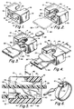
- a preferred embodiment of a unidirectional closure means 10 is shown for use with an identification bracelet or band 20 and constructed in accordance with the teachings of the invention.
- the closure means 10 is preferably manufactured as an integral piece of plastic or other suitably strong, lightweight material, by injection molding or other suitable process.
- the band 20 is preferably fabricated from plastic or vinyl or other suitably flexible, lightweight material, and may be adapted to include identifying information thereon or to otherwise serve an identifying function relating to an object or person.
- the manufacture, design and identification features of bands such as band 20 are known and understood by those of ordinary skill in the art, and may include multi-layer laminates (see FIGS. 3-5, for example) or other constructions.
- identifying function can be accomplished in a wide variety of ways, including, by way of further example, placing identifying indicia on the closure means itself, color coding the band 20 and/or the closure means 10, etc.
- the band 20 includes a first end 22 and a second end 24, FIGS. 3-6, remote from the first end 22.
- the band as well as its first and second ends, is sized and shaped so that it can encircle the object or person to be identified (such as, for example, by encircling a person's wrist) and be usefully retained thereon. In the preferred embodiment, this retention is accomplished by unidirectionally adjustable closure means 10 which retains the first and second ends adjacent each other about the object, as will now be described in further detail.
- the closure means 10 is preferably configured as a sleeve or body portion 12 having a generally rectangular cross-section. This cross-section is formed by an upper wall 14, a lower wall 16, and sidewalls 18 and 19 connecting the upper and lower walls 14 and 16.
- the lower wall 16 has an upper surface 30 on which a mounting post 32 is disposed, preferably by integrally molding the mounting post 32 with the body portion 12.
- the band means 20 includes an opening 26 near the first end 22 of the band, which opening is configured to matingly engage the mounting post 32.
- the mounting post 32 is preferably deformed such as by bending (as illustrated in FIG. 3) or otherwise, so that the first end 22 cannot be easily removed or detached from the body portion 12.
- the upper wall 14 preferably includes an opening 17 therein. The opening 17 facilitates automated or manual access to the mounting post with an appropriate tool to accomplish the deformation.
- a plurality of mounting posts 32 could be provided integrally molded with the body portion 12.
- band means 20 would include a correspondingly configured multiplicity of openings 26 to matingly engage the plurality of mounting posts.
- the upper wall 14 would preferably include a corresponding plurality of openings 17 therein.
- the bracelet means 20 is assembled about the object or person to be identified.
- the bracelet 20 is assembled about the newborn's wrist or ankle in an encircling relationship.
- the second end 24, FIGS. 3 and 4 is inserted through an opening 15 (FIGS. 1 and 5) in the body portion or sleeve 12.
- the second end 24 can be inserted and pulled through the opening 15 in a first direction (as indicated by the arrows in FIGS. 3 and 4) until the bracelet forms a ring (see FIG. 6) of a desirable size.
- the circumference of the ring is preferably large enough to permit the child to be comfortable but small enough so that the bracelet cannot easily be slipped over the infant's hand or foot.
- excess length of the second end 24 can be severed from the rest of the bracelet by cutting or the like, FIG. 6.
- the bracelet assembly can be removed from the object or person by, for example, cutting the band means 20 or by otherwise destroying or damaging the bracelet.
- the second end 24 is retained by the closure means 10 by unidirectional gripping or engagement means 40 such as one or more engagement members or protruding teeth 42.
- the teeth 42 include biting extremities 44 and preferably are configured and oriented to protrude into the center of the sleeve 12 so that the extremities 44 contact the second end 24 of the band means 20.
- the sleeve 12 preferably includes an urging portion 46 such as one or more curved shoulders, FIGS. 2-5.
- the urging portion 46 is configured and dimensioned to help urge the second end 24 against the biting extremities 44.
- one important benefit of this invention is that it permits the second end 24 to slide further in the first direction relative to the closure means 10, but prevents any such relative motion in the second and opposite direction.
- this is of substantial benefit, for example, when a newborn child loses weight and its wrists, hands, feet and ankles "shrink". In such circumstances, the bracelet can simply be "tightened” an appropriate amount to ensure the desired retention of the bracelet on the infant.
- the teeth 42 are preferably fabricated integrally with the rest of the closure means 10. Because of this unitary fabrication, the unit cost for materials and assembly of the closure 10 and the complete bracelet assembly is reduced, and the overall manufacture and assembly process is simplified. Those skilled in the art will understand that the particular material from which the closure 10 is fabricated, and the specific dimensions of the teeth 42, the urging portion 46 and the opening 15 are selected to ensure the ready insertion of the second end 24 through the sleeve 12 as well as the desired engagement of the teeth 42 with the second end 24.
- the materials and dimensions of the teeth 42 and their biting extremities 44 must be such as to achieve the necessary contact between the teeth and the second end 24, even when no movement of the second end 24 relative to the closure means 10 occurs.
- the teeth must be properly engaged with the second end 24 at all relevant times. Absent such proper engagement, the second end 24 could be withdrawn from the closure and the bracelet removed from the desired encircling relationship about the object or the wearer's wrist or ankle.
- the thickness of the band or bracelet 20 is a factor in determining the specific dimensions of the teeth, etc.
Landscapes
- Physics & Mathematics (AREA)
- General Physics & Mathematics (AREA)
- Engineering & Computer Science (AREA)
- Theoretical Computer Science (AREA)
- Adornments (AREA)
- Buckles (AREA)
- Measurement Of The Respiration, Hearing Ability, Form, And Blood Characteristics Of Living Organisms (AREA)
- Professional, Industrial, Or Sporting Protective Garments (AREA)
Description
Claims (6)
- A closure means (10) for an identification band (20) which band has first and second ends (22,24) and is adapted to encircle a portion of a person or an object to be identified, comprising the combination of: a body portion (12); attachment means on said body portion (12) for attaching the first end (22) of the band (20) to said body portion (10); an opening (15) in said body portion (12) for receiving the second end (24) of the band (20) after the band encircles the portion of the person or object; unidirectional engagement means (40) formed integrally as a unitary structure with said body portion (12) for engaging the second end (24) of the band (20) after it has been inserted through said opening (15), said engagement means (40) being configured and oriented to permit further insertion of the second end (24) of the band (20) through said opening (15) but to prevent retraction of the second end (24) of the band (20) from said opening (15), characterised in that the second end (24) having a smooth surface on at least a portion thereof, and in that said engagement means (40) constituting infinitely adjustable engagement means (40) capable of engaging the second end (24) at any position along its length within a given range by biting into the smooth surface.
- The closure means (10) of claim 2, in which said unidirectional engagement means (40) includes one or more protruding teeth (40) having a biting extremity (44) in abutting contact with the second end (24) of the band (20) after the second end (24) has been inserted a sufficient distance through said opening (15), said biting extremity (44) being oriented to permit the second end (24) of the band (20) to slide past said biting extremity (44) as the second end (24) is inserted further through said opening (15) but to prevent retraction of the second end (24) from said opening (15).
- The closure means (10) of claim 1, in which said closure means (10) further includes an urging portion (46) on an opposite side of said opening (15) from said unidirectional engagement means (40), to urge the second end (24) of the band (20) into operably abutting contact with said engagement means (40).
- The closure means (10) of claim 1 or claim 2 or claim 3, in which said body portion (12) constitutes a sleeve (12) having an approximately rectangular cross-section, said sleeve (12) having an upper wall (14), a lower wall (16), and two side walls (18,19) connecting said upper wall (14) and said lower wall (16) to each other; said lower wall (14) having one or more deformable mounting posts (32) on a surface (30) facing said upper wall (14), and said first end (22) of said band means (20) having one or more corresponding openings (26) therein to matingly engage said mounting post or posts (32), after which said mounting post or posts (32) are deformed to maintain said operable attachment of said body portion (12) to said first end (22) of said band means (20).
- The closure means (10) of claim 4, in which said upper wall (14) includes one or more openings (17) therein to facilitate said deformation of said mounting post or posts (32).
- The closure means (10) of claims 1-5 in which said closure means (10) constitutes means for permitting the tightening of said band means (20) about the person or object after the initial assembly of said band means (20) about the person or object, in which said subsequent tightening can be to any size within said same or a similar given range.
Applications Claiming Priority (3)
| Application Number | Priority Date | Filing Date | Title |
|---|---|---|---|
| US91260 | 1993-07-15 | ||
| US08/091,260 US5479797A (en) | 1993-07-15 | 1993-07-15 | Unidirectionally sizeable bracelet assembly and closure means therefor |
| PCT/US1994/007796 WO1995002343A1 (en) | 1993-07-15 | 1994-07-11 | Uni-directionally sizable bracelet assembly and closure means therefor |
Publications (3)
| Publication Number | Publication Date |
|---|---|
| EP0708607A1 EP0708607A1 (en) | 1996-05-01 |
| EP0708607A4 EP0708607A4 (en) | 1996-06-26 |
| EP0708607B1 true EP0708607B1 (en) | 2000-06-07 |
Family
ID=22226857
Family Applications (1)
| Application Number | Title | Priority Date | Filing Date |
|---|---|---|---|
| EP94922528A Expired - Lifetime EP0708607B1 (en) | 1993-07-15 | 1994-07-11 | Uni-directionally sizable bracelet assembly and closure means therefor |
Country Status (7)
| Country | Link |
|---|---|
| US (1) | US5479797A (en) |
| EP (1) | EP0708607B1 (en) |
| JP (1) | JPH09500301A (en) |
| AU (1) | AU679547B2 (en) |
| DE (1) | DE69424870T2 (en) |
| ES (1) | ES2148337T3 (en) |
| WO (1) | WO1995002343A1 (en) |
Families Citing this family (28)
| Publication number | Priority date | Publication date | Assignee | Title |
|---|---|---|---|---|
| GB2290940A (en) * | 1994-07-05 | 1996-01-17 | Decca Jewellery Company Limite | Adjustable bracelet |
| USD383379S (en) * | 1995-12-11 | 1997-09-09 | Keegan Jonathan D | Electrical securing cord |
| US5848454A (en) * | 1996-11-12 | 1998-12-15 | Kojima; Kimberly | Strapping system and fastener therefor |
| US7374081B2 (en) * | 1997-03-12 | 2008-05-20 | Precision Dynamics Corporation | Identification device having reusable transponder |
| US7198190B2 (en) * | 1997-03-12 | 2007-04-03 | Dodge Juhan | Identification device having reusable transponder |
| US5941019A (en) * | 1997-12-23 | 1999-08-24 | Nursery Supplies, Inc. | Nursery container with attachment device |
| ATE471088T1 (en) * | 1998-04-23 | 2010-07-15 | Builmatel Co Ltd | BUCKLE |
| US6453519B1 (en) | 1999-08-06 | 2002-09-24 | Sagoma Plastics Corporation | Buckle |
| US6655063B2 (en) | 2001-10-22 | 2003-12-02 | Teresa S. Goodin | Safe and secure baby identification system |
| US7316358B2 (en) * | 2002-03-18 | 2008-01-08 | Precision Dynamics Corporation | Identification band with adhesively attached coupling elements |
| US7204425B2 (en) * | 2002-03-18 | 2007-04-17 | Precision Dynamics Corporation | Enhanced identification appliance |
| US20030174049A1 (en) * | 2002-03-18 | 2003-09-18 | Precision Dynamics Corporation | Wearable identification appliance that communicates with a wireless communications network such as bluetooth |
| US20050205202A1 (en) * | 2003-03-24 | 2005-09-22 | Precision Dynamics Corporation | Continuous lamination of RFID tags and inlets |
| US20040188010A1 (en) * | 2003-03-24 | 2004-09-30 | Chaoui Sam M. | Continuous lamination of RFID bands and inlets |
| JP2007504064A (en) * | 2003-05-22 | 2007-03-01 | フィジカル システムズ インコーポレイテッド | Cable ties |
| US20050091896A1 (en) * | 2003-10-30 | 2005-05-05 | Kotik Mark M. | Identification band with detachable machine-readable lables |
| US7188764B2 (en) * | 2004-12-16 | 2007-03-13 | Precision Dynamics Corporation | Method for effecting ticket-based transactions using a wristband |
| US8336239B2 (en) * | 2006-11-09 | 2012-12-25 | St. John Companies, Inc. | Wristband and clasp therefor |
| US7631449B2 (en) * | 2006-11-09 | 2009-12-15 | The St. John Companies, Inc. | Wristband and clasp therefor |
| TWM326400U (en) * | 2007-03-06 | 2008-02-01 | Swepo Co Ltd | Structure of identifying ring |
| US8028450B2 (en) * | 2008-07-31 | 2011-10-04 | Typenex Medical, Llc | Recipient verification systems and methods of use including recipient identification |
| USD622128S1 (en) | 2009-09-25 | 2010-08-24 | MCL Design, Inc. | Hinge |
| USD673071S1 (en) * | 2010-08-30 | 2012-12-25 | Cube Services, Inc. | Wrist band clasp |
| US9299271B2 (en) | 2010-10-05 | 2016-03-29 | Xpress Systems, Llc | Tear-resistant wristband |
| WO2017083965A1 (en) * | 2015-11-17 | 2017-05-26 | Rivard Louis-Philippe | Tie wrap connector and strap kit |
| USD782053S1 (en) | 2016-01-05 | 2017-03-21 | Rhonda Ferguson-Shakir | Diagnostic wrist band |
| USD782052S1 (en) | 2016-01-05 | 2017-03-21 | Rhonda Ferguson-Shakir | Diagnostic wrist band |
| USD974207S1 (en) * | 2020-02-05 | 2023-01-03 | Baby Minder LLC | Child car seat belt buckle safety indicator |
Family Cites Families (11)
| Publication number | Priority date | Publication date | Assignee | Title |
|---|---|---|---|---|
| US3106028A (en) * | 1960-05-26 | 1963-10-08 | John G Baumgartner | Identification band |
| US3279107A (en) * | 1964-03-04 | 1966-10-18 | John G Baumgartner | Identification band |
| GB1291172A (en) * | 1970-02-05 | 1972-10-04 | Steer Dev Ltd Peter | Straps |
| US3800450A (en) * | 1972-03-31 | 1974-04-02 | Laugherty Inc | Identification band |
| GB1544163A (en) * | 1976-09-27 | 1979-04-11 | Promex Plastics Ltd | Identification band |
| US4183119A (en) * | 1978-05-15 | 1980-01-15 | Dennison Manufacturing Company | Harnessing device with gripper rails |
| US4499680A (en) * | 1982-01-29 | 1985-02-19 | Coburn James A | Identification band |
| US4616436A (en) * | 1985-01-17 | 1986-10-14 | Woskin Irvin S De | Identification band |
| US5102075A (en) * | 1990-01-04 | 1992-04-07 | Tyton Corporation | Bundle tie |
| US5031943A (en) * | 1990-04-02 | 1991-07-16 | Edge Technology Corporation | Closure strap for flexible containers |
| CA2047945C (en) * | 1990-08-02 | 1995-04-04 | William A. Fortsch | Cable tie having improved locking barb |
-
1993
- 1993-07-15 US US08/091,260 patent/US5479797A/en not_active Expired - Lifetime
-
1994
- 1994-07-11 WO PCT/US1994/007796 patent/WO1995002343A1/en not_active Ceased
- 1994-07-11 DE DE69424870T patent/DE69424870T2/en not_active Expired - Fee Related
- 1994-07-11 EP EP94922528A patent/EP0708607B1/en not_active Expired - Lifetime
- 1994-07-11 AU AU73600/94A patent/AU679547B2/en not_active Ceased
- 1994-07-11 ES ES94922528T patent/ES2148337T3/en not_active Expired - Lifetime
- 1994-07-11 JP JP7504661A patent/JPH09500301A/en active Pending
Also Published As
| Publication number | Publication date |
|---|---|
| DE69424870T2 (en) | 2000-10-19 |
| EP0708607A4 (en) | 1996-06-26 |
| US5479797A (en) | 1996-01-02 |
| WO1995002343A1 (en) | 1995-01-26 |
| AU679547B2 (en) | 1997-07-03 |
| DE69424870D1 (en) | 2000-07-13 |
| AU7360094A (en) | 1995-02-13 |
| ES2148337T3 (en) | 2000-10-16 |
| EP0708607A1 (en) | 1996-05-01 |
| JPH09500301A (en) | 1997-01-14 |
Similar Documents
| Publication | Publication Date | Title |
|---|---|---|
| US5479797A (en) | Unidirectionally sizeable bracelet assembly and closure means therefor | |
| US3106028A (en) | Identification band | |
| US5414903A (en) | Single use, disposable dental bib holder system | |
| US6446474B1 (en) | Key operable restraining device with spike engaging member | |
| US5323554A (en) | Tube identification band | |
| US5320097A (en) | Endotracheal tube holding and securing device | |
| US4523586A (en) | Protective cover for a limb or a cast | |
| US5979095A (en) | Identification bracelet and clasp construction therefor | |
| EP1495459B1 (en) | An information band | |
| US7861443B2 (en) | Identification tag and releasable attachment clip | |
| US9668551B2 (en) | Clasp system | |
| CA2222387A1 (en) | Plastic fastener for threaded blind aperture | |
| EP4115763A1 (en) | Wristband and wrist wearable device | |
| US6976327B2 (en) | Safe and secure baby identification system | |
| US5245732A (en) | Jewelry clasp | |
| AU598338B2 (en) | Novel preset necktie | |
| US4998327A (en) | Traction hook and rope lock | |
| US6513685B1 (en) | Ring securing device | |
| US20060272367A1 (en) | Attachable restraining device | |
| EP0742159A1 (en) | A bundling strap assembly | |
| JPH0613516U (en) | Tie | |
| US7228821B2 (en) | Adjustable quick release pet collar | |
| US5203057A (en) | Piggy back jewelry catch | |
| US1561631A (en) | Antithumb-sucking device | |
| EP1009250A4 (en) | Jewelry retention system |
Legal Events
| Date | Code | Title | Description |
|---|---|---|---|
| PUAI | Public reference made under article 153(3) epc to a published international application that has entered the european phase |
Free format text: ORIGINAL CODE: 0009012 |
|
| 17P | Request for examination filed |
Effective date: 19960119 |
|
| AK | Designated contracting states |
Kind code of ref document: A1 Designated state(s): DE ES FR GB IT NL SE |
|
| A4 | Supplementary search report drawn up and despatched |
Effective date: 19960508 |
|
| AK | Designated contracting states |
Kind code of ref document: A4 Designated state(s): DE ES FR GB IT NL SE |
|
| 17Q | First examination report despatched |
Effective date: 19981113 |
|
| GRAG | Despatch of communication of intention to grant |
Free format text: ORIGINAL CODE: EPIDOS AGRA |
|
| GRAG | Despatch of communication of intention to grant |
Free format text: ORIGINAL CODE: EPIDOS AGRA |
|
| GRAH | Despatch of communication of intention to grant a patent |
Free format text: ORIGINAL CODE: EPIDOS IGRA |
|
| GRAH | Despatch of communication of intention to grant a patent |
Free format text: ORIGINAL CODE: EPIDOS IGRA |
|
| GRAA | (expected) grant |
Free format text: ORIGINAL CODE: 0009210 |
|
| AK | Designated contracting states |
Kind code of ref document: B1 Designated state(s): DE ES FR GB IT NL SE |
|
| REF | Corresponds to: |
Ref document number: 69424870 Country of ref document: DE Date of ref document: 20000713 |
|
| ITF | It: translation for a ep patent filed | ||
| ET | Fr: translation filed | ||
| REG | Reference to a national code |
Ref country code: ES Ref legal event code: FG2A Ref document number: 2148337 Country of ref document: ES Kind code of ref document: T3 |
|
| PLBE | No opposition filed within time limit |
Free format text: ORIGINAL CODE: 0009261 |
|
| STAA | Information on the status of an ep patent application or granted ep patent |
Free format text: STATUS: NO OPPOSITION FILED WITHIN TIME LIMIT |
|
| 26N | No opposition filed | ||
| REG | Reference to a national code |
Ref country code: GB Ref legal event code: IF02 |
|
| PGFP | Annual fee paid to national office [announced via postgrant information from national office to epo] |
Ref country code: SE Payment date: 20050714 Year of fee payment: 12 Ref country code: NL Payment date: 20050714 Year of fee payment: 12 |
|
| PGFP | Annual fee paid to national office [announced via postgrant information from national office to epo] |
Ref country code: ES Payment date: 20050719 Year of fee payment: 12 |
|
| PG25 | Lapsed in a contracting state [announced via postgrant information from national office to epo] |
Ref country code: SE Free format text: LAPSE BECAUSE OF NON-PAYMENT OF DUE FEES Effective date: 20060712 |
|
| PG25 | Lapsed in a contracting state [announced via postgrant information from national office to epo] |
Ref country code: NL Free format text: LAPSE BECAUSE OF NON-PAYMENT OF DUE FEES Effective date: 20070201 |
|
| EUG | Se: european patent has lapsed | ||
| NLV4 | Nl: lapsed or anulled due to non-payment of the annual fee |
Effective date: 20070201 |
|
| REG | Reference to a national code |
Ref country code: ES Ref legal event code: FD2A Effective date: 20060712 |
|
| PG25 | Lapsed in a contracting state [announced via postgrant information from national office to epo] |
Ref country code: ES Free format text: LAPSE BECAUSE OF NON-PAYMENT OF DUE FEES Effective date: 20060712 |
|
| PGFP | Annual fee paid to national office [announced via postgrant information from national office to epo] |
Ref country code: DE Payment date: 20080722 Year of fee payment: 15 |
|
| PGFP | Annual fee paid to national office [announced via postgrant information from national office to epo] |
Ref country code: FR Payment date: 20090716 Year of fee payment: 16 |
|
| PGFP | Annual fee paid to national office [announced via postgrant information from national office to epo] |
Ref country code: GB Payment date: 20090720 Year of fee payment: 16 |
|
| PGFP | Annual fee paid to national office [announced via postgrant information from national office to epo] |
Ref country code: IT Payment date: 20090723 Year of fee payment: 16 |
|
| PG25 | Lapsed in a contracting state [announced via postgrant information from national office to epo] |
Ref country code: DE Free format text: LAPSE BECAUSE OF NON-PAYMENT OF DUE FEES Effective date: 20100202 |
|
| GBPC | Gb: european patent ceased through non-payment of renewal fee |
Effective date: 20100711 |
|
| REG | Reference to a national code |
Ref country code: FR Ref legal event code: ST Effective date: 20110331 |
|
| PG25 | Lapsed in a contracting state [announced via postgrant information from national office to epo] |
Ref country code: IT Free format text: LAPSE BECAUSE OF NON-PAYMENT OF DUE FEES Effective date: 20100711 Ref country code: FR Free format text: LAPSE BECAUSE OF NON-PAYMENT OF DUE FEES Effective date: 20100802 |
|
| PG25 | Lapsed in a contracting state [announced via postgrant information from national office to epo] |
Ref country code: GB Free format text: LAPSE BECAUSE OF NON-PAYMENT OF DUE FEES Effective date: 20100711 |