EP0708425B1 - A clip assembly - Google Patents
A clip assembly Download PDFInfo
- Publication number
- EP0708425B1 EP0708425B1 EP19950202711 EP95202711A EP0708425B1 EP 0708425 B1 EP0708425 B1 EP 0708425B1 EP 19950202711 EP19950202711 EP 19950202711 EP 95202711 A EP95202711 A EP 95202711A EP 0708425 B1 EP0708425 B1 EP 0708425B1
- Authority
- EP
- European Patent Office
- Prior art keywords
- clip member
- leaf spring
- clip
- housing
- clip assembly
- Prior art date
- Legal status (The legal status is an assumption and is not a legal conclusion. Google has not performed a legal analysis and makes no representation as to the accuracy of the status listed.)
- Expired - Lifetime
Links
Images

Classifications
-
- G—PHYSICS
- G08—SIGNALLING
- G08B—SIGNALLING OR CALLING SYSTEMS; ORDER TELEGRAPHS; ALARM SYSTEMS
- G08B3/00—Audible signalling systems; Audible personal calling systems
- G08B3/10—Audible signalling systems; Audible personal calling systems using electric transmission; using electromagnetic transmission
- G08B3/1008—Personal calling arrangements or devices, i.e. paging systems
- G08B3/1016—Personal calling arrangements or devices, i.e. paging systems using wireless transmission
- G08B3/1025—Paging receivers with audible signalling details
- G08B3/1058—Pager holders or housings
-
- A—HUMAN NECESSITIES
- A45—HAND OR TRAVELLING ARTICLES
- A45F—TRAVELLING OR CAMP EQUIPMENT: SACKS OR PACKS CARRIED ON THE BODY
- A45F5/00—Holders or carriers for hand articles; Holders or carriers for use while travelling or camping
- A45F5/02—Fastening articles to the garment
-
- A—HUMAN NECESSITIES
- A45—HAND OR TRAVELLING ARTICLES
- A45F—TRAVELLING OR CAMP EQUIPMENT: SACKS OR PACKS CARRIED ON THE BODY
- A45F2200/00—Details not otherwise provided for in A45F
- A45F2200/05—Holder or carrier for specific articles
- A45F2200/0516—Portable handheld communication devices, e.g. mobile phone, pager, beeper, PDA, smart phone
Definitions
- the present invention relates to a clip assembly for use with a portable electric or electronic apparatus, in particular a portable electronic telecommunication device such as a portable cordless or mobile telephone, a radio pager and the like.
- Clip assemblies of the type according to the present invention comprise a clip member or a clip hook which is resiliently biased towards the body or housing of a device to which the clip assembly is attached.
- an object such as a piece of garment, a pocket, or a belt can be received between the clip member and the body or housing of the device.
- the clip assembly can be either directly connected to the body or housing of the device or by a separate attachment member or mounting bracket.
- US-A-3,710,423 discloses a clamping device for clamping an article to a perforated board.
- the resilient biasing means are secured to the board by a separate mounting bracket.
- Prior art clip assemblies such as disclosed by EP-A-0,552,962; US-A-4,780,934 and US-A-4,536,925 generally comprise a support structure having a hinge shaft, a separate attachment member or mounting bracket to which the clip assembly is fixedly mounted, fastening lugs on the clip member and the attachment member for supporting the shaft, and biasing means formed by small torsion springs or small leaf springs.
- the biasing springs act on the clip member at or near the hinge point thereof.
- the support and biasing structure of these known clip assemblies is structurally rather complicated, comprising a number of small parts, which are not only difficult to assemble but are also prone to damage.
- an external force is exerted on the clip member, for example when the portable strikes upon a table or the like or when the portable hooks behind an arm of a chair or another object and is forcefully removed, besides breakage of a lug or lugs the clip assemblies can fall to pieces and are then difficult to reassemble.
- US-A-5,016,326 discloses a clip assembly comprising a clip member or a clip hook and biasing leaf spring means.
- One end of the clip member is pivotally mounted at the body or housing of a device, such that an opposite receiving end of the clip member can be raised from the body or housing of the device for the receipt of a piece of garment or another object.
- One end of the leaf spring means engages the clip member at its pivot point whereas an opposite end of the leaf spring means extends in the direction of the receiving end of the clip member and is supported by the body or housing of the device.
- the receiving opening of this known device is, however, limited to such part of the receiving end of the clip member which, if viewed from its pivot point, projects beyond the support point of the leaf spring means at the body or housing of the device.
- a first object of the invention is to provide a clip assembly of the type having a pivotable clip member or clip hook and biasing means, which clip assembly is compact in size and relatively easy to assemble with as little as possible small and/or separate parts, and without the need for a separate support of the biasing means at the body or housing to which the clip assembly is attached.
- a clip assembly for attachment to a body or housing, comprising an elongated clip member having a first end and a second end, hinge means arranged between said first end and second end for pivotally mounting the clip member, and leaf spring means extending in longitudinal direction of the clip member for biasing the first end of the clip member toward the body or housing and wherein a first end of the leaf spring means engages the clip member at a position between the first end and the second end thereof, characterized in that a second end of the leaf spring means extends freely in the direction of the second end of the clip member, the leaf spring means having a spring force so that when attached to a body or housing the second end of the leaf spring means is urged towards the body or housing.
- the clip assembly according to the invention with its longitudinally extending leaf spring means, combines a small size with a high biasing force, i.e. clamping or holding force, which is an important advantage in view of the trend towards smaller sizes for portable telecommunication devices and the like.
- the leaf spring means With the clip assembly of the invention the leaf spring means, with their second end, extend freely in the direction of the second end of the clip member, such that there is no need for a separate support of the leaf spring means at the body or housing of the device to which the clip assembly is to be attached.
- the clip assembly of the invention comprises a common single mounting point, i.e. its hinge means for pivotally mounting the clip assembly to a body or housing of a device, such that attachment of the clip assembly can be established without having to use a separate attachment member, mounting bracket etc.
- the hinge means are advantageously configured for releasable attachment by snap fitting on the body or housing. Suitable snap fittings are known per se in practice.
- an object projecting a certain distance beyond the first end of the clip member in the direction of the second end of the clip member can be received between the clip member and the body or housing of a device without impeding the biasing force of the leaf spring means. Accordingly, a relatively large receiving opening is provided for the receipt of an object.
- leaf spring means used in the present description and the claims is to be construed as comprising any resilient means having a spring action comparable to a leaf spring.
- the leaf spring means comprise at least one single leaf spring, the first end of which is attached the clip member at or near the first end thereof.
- the leaf spring can be made of a plastic material or a metal.
- the leaf spring is attached to the clip member by means of a separate grip piece provided at the first end of the clip member, for frictionally holding the clip to a piece of a garment or the like.
- the clip member is provided, at its outwardly facing surface, with a recess which connects to an opening for receiving the grip piece.
- the grip piece has a first part which closes off the recess and a second part which, through the opening, extends from the clip member in the direction of the body or housing.
- This second part of the grip piece has a slit for receiving the first end of the leaf spring, such that in its assembled state the first end of the leaf spring is positioned and held in the recess by means of the grip piece.
- the clip piece which is preferably made of rubber, an easy to assemble and to reassemble clip assembly is provided.
- the recess and the leaf spring are provided with complementary connecting projections and cut outs.
- the projections are preferably formed in the recess and are inclined towards the first end of the clip member, in order to provide a self latching effect of the leaf spring and the clip member during and after their assembly.
- the leaf spring means are integrally formed with the clip member and may comprise a pair of lip shaped leaf springs positioned at each side of the clip member.
- the lips can be made out of the plane of the clip member, for example in the form of a single loop shaped configuration which extends from part of the circumference of the clip member. It is, however, also possible to use separate lip shaped leaf spring means which are completely or partly embedded in or covered by the material of the clip member.
- the clip assembly is just comprised of one single piece.
- the clip assembly according to the invention is designed for use without a separate attachment member, it will be understood that whenever a separate attachment member is preferred or needed, e.g. in case of replacement of a prior art clip assembly by the clip assembly of the invention, the latter can be provided mounted at such attachment member. This while maintaining all the other features and advantages as mentioned above.
- the invention relates also to a portable electronic apparatus, in particular a portable electronic telecommunication device such as a cordless or mobile telephone or radio pager, comprising the novel and inventive clip assembly as described above.
- a portable electronic apparatus in particular a portable electronic telecommunication device such as a cordless or mobile telephone or radio pager, comprising the novel and inventive clip assembly as described above.
- Fig. 1 is a schematic side view illustrating a cordless portable telephone provided with a clip assembly according to the invention.
- Figs. 2 and 3 are schematic cross sections on an enlarged scale through part of the portable telephone shown in Fig. 1, illustrating the clip assembly in different positions.
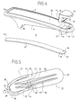
- Fig. 4 is a schematic perspective exploded view of the clip assembly shown in Figs. 2 and 3, illustrating the several parts of the clip assembly before assembly thereof.
- Fig. 5 is a schematic perspective view of the clip assembly according the invention, illustrating a clip member and leaf spring means integrally formed with the clip member.
- Fig. 1 shows in a side view a cordless or mobile portable telephone 1, having a plastic body or housing 2 with a front face 3, provided with several push buttons 4 for operating the telephone, and a back or rear face 5, to which a clip assembly 6 according to the present invention is attached.
- the clip assembly 6 comprises an elongated plastic clip member or clip hook 7 which is pivotally connected to the rear face 5 of the body or housing 2.
- Fig. 2 shows, on an enlarged scale, part of the clip assembly 6 and the body or housing 2 of Fig. 1.
- the clip assembly comprises biasing means in the form of a leaf spring 8 and hinge means in the form of a support section 9 which is formed as an integral part of the clip member 7.
- the support section 9 has a protruding shaft like attachment part 10 which is configured for pivotally releasable snap insertion into a complementary recess 11 of the body or housing 2.
- the support section 9 is positioned between a first end 12 and a second end 13 of the clip member 7, such that the hinge point formed by the attachment part 10 is closer to the second end 13.
- the clip member 7 terminates in a barb-like projection 14.
- the clip member 7 is also provided with a grip piece 15 of rubber or the like.
- a part 16 of this grip piece 15 is received in a recess 19 formed in the outwardly facing surface 20 of the clip member 7, whereas another part 17 of the grip piece 15, making right angles with the part 16, is received in a through opening 21 which connects to the recess 19 adjacent the projection 14, viewed in the direction of the second end 13 of the clip member 7.
- the part 17 of the grip piece 15 is dimensioned such that, when assembled, this part 17 projects from the clip member 7 to form with the projection 14 an integral barb shaped end of the clip member 7.
- the biasing leaf spring 8 which can be of plastic or a suitable metal such as stainless steel, has a first end 23 which is attached to the clip member 7 at its first end 12, and a second end 24 which extends freely in the direction of the second end 13 of the clip member 7 beyond the hinge point thereof. At its first end 23 the leaf spring 8 is received in the recess 19 through a slit or slot 18 in the part 17 of the grip piece 15.
- the leaf spring 8 has a spring force or tension which urges the clip member 7 with its first end 12 towards the rear face 5 of the body or housing 2 until it is stopped by the grip piece 15 making contact with the rear face 5, and urges the second end 24 of the leaf spring 8 towards and against the rear face 5 of the body or housing 2, as shown.
- Fig. 3 shows the clip member 7 in a lifted position, such that there is formed a receiving opening 22 between the rear face 5 and the grip piece 15, i.e. the first end 12 of the clip member 7, for receiving a piece of garment or a belt or the like, not shown.
- the clip member 7 can be lifted either by pushing its second end 13 towards the rear face 5 of the body or housing or by raising the first receiving end 12 of the clip member 7 with respect to the rear face 5 of the body or housing 2.
- the clip member 7, under the biasing force of the leaf spring 8, returns to the position shown in Fig. 2.
- the piece of garment is clamped to the body or housing 2 by the clip member 7, i.e. its grip piece 15.
- the clamping strength depends mainly on the spring characteristics of the leaf spring 8, its dimensions and the positions at which the leaf spring engages the clip member 7 and the body or housing 2.
- the grip piece 15 of rubber provides an additional frictional force to the piece of garment.
- the support section 9 is shaped such that the leaf spring 8 from its first end 23 extends for the greater part within the circumference of the clip member 7. Accordingly, an object received in the receiving opening 22 will not impede or otherwise have an influence on or is obstructed by the leaf spring 8.
- the mechanical force exerted on the clip member 7 is properly distributed along the length thereof.
- the clip member 7 is biased for the greater part by the relatively high spring force of the leaf spring 8 acting in longitudinal direction thereof.
- the clamping force of the clip assembly can be further controlled by limiting the travel of the second free end 24 of the leaf spring 8, for example by providing at the rear side or back 5 of the body or housing 2 a groove in which the second end 24 is received and/or can slide (not shown).
- Fig. 4 shows the several parts of the clip assembly 6 in their disassembled form.
- the recess 19 in the clip member 7 is provided with two semi-circular projections 25, of which only one is shown. These projections are raised in the direction of the first end 12 and towards the outwardly facing side 20 of the clip member 7.
- the leaf spring 8 is at its first end 23 provided with complementary semi-circular like cut outs 26, as shown.
- the clip assembly 6 can be very easily assembled by pushing the grip piece 15 into the recess 19 of the clip member 7, as shown, while simultaneously inserting the leaf spring 8 with its first end 23 through the slot 18 of the grip piece 15 into the recess 19.
- the corresponding semi-circular protrusions and cut outs 25, 26 will snap into each other in a self-aligning manner.
- the grip piece 15 and the leaf spring 8 hold each other in position without the need for additional fixing means such as screws, rivets or the like. It will be understood that by the absence of small parts, the clip assembly is very easily to assemble and to reassemble in case it has been fallen to pieces, without a need for special tools or skills. Further, the clip member and leaf spring can be kept in stock as spare parts.
- the opening 21 is also very advantageously from a moulding point of view.
- the mould has to be provided with a relatively complicated structure of mould slide means.
- the projection 14 at the first end 12 can be formed in one step with the opening 21, such that a relatively simple single mould slide structure for forming the attachment part 10 suffices.
- Fig. 5 illustrates a further embodiment of a clip assembly 27 based on the concept of the invention.
- a elongated plastic clip member 28 having a first end 29 and a second end 30 and leaf spring means 31.
- the leaf spring means 31 take the form of two lip shaped leaf springs 32, 33 each positioned at a longitudinal edge of the clip member 28. With their first ends 34 the leaf springs 32, 33 are connected to the clip member 28 between the first end 29 and the second end 30 thereof, whereas the second ends 35 of the leaf springs 32, 33 are mutually connected to form a single loop shaped configuration which extends in the direction of the second end 30 of the clip member 28.
- the clip member comprises hinge means in the form of two parallel support sections 36 which are formed as an integral part of the clip member 28.
- the support sections 36 have protruding attachment parts 37, each comprising oppositely directed semi-spherical protrusions 38 which are configured for pivotally releasable snap insertion in complementary recesses provided in the body or housing to which the clip member is to be attached, or in a separate attachment member, not shown.
- the loop shaped spring means 31 and the support sections 36 are formed in one piece from the material of the clip member 28. As indicated by a dot/dashed line 39 it is also possible to have separate leaf spring means embedded in or covered by the plastic of the clip member 28. It will be understood that this is a very attractive embodiment, because the clip assembly as a whole comprises essentially one single part.
- the support or hinge sections 9, 36 of the clip assemblies 6, 27 can be mutually substituted or replaced by other known support sections. It is of course not mandatory to use releasable support means, in particular the snap fittings shown.
- the clip assembly is further not restricted to the use of plastic material or the connection of the leaf spring 8 to the clip member 7 by means of the grip piece 15. Such connection can also be made by means of screws, rivets and the like or by embedding the first end 23 of the leaf spring 8 in the clip member 7.
Description
- The present invention relates to a clip assembly for use with a portable electric or electronic apparatus, in particular a portable electronic telecommunication device such as a portable cordless or mobile telephone, a radio pager and the like.
- Clip assemblies of the type according to the present invention comprise a clip member or a clip hook which is resiliently biased towards the body or housing of a device to which the clip assembly is attached. By lifting the clip member against its biasing force, an object such as a piece of garment, a pocket, or a belt can be received between the clip member and the body or housing of the device. After release of the clip member, due to the biasing force acting on the clip member, the device and the object are mutually firmly clamped. The clip assembly can be either directly connected to the body or housing of the device or by a separate attachment member or mounting bracket.
- US-A-3,710,423 discloses a clamping device for clamping an article to a perforated board. In use, the resilient biasing means are secured to the board by a separate mounting bracket.
- Prior art clip assemblies, such as disclosed by EP-A-0,552,962; US-A-4,780,934 and US-A-4,536,925 generally comprise a support structure having a hinge shaft, a separate attachment member or mounting bracket to which the clip assembly is fixedly mounted, fastening lugs on the clip member and the attachment member for supporting the shaft, and biasing means formed by small torsion springs or small leaf springs. The biasing springs act on the clip member at or near the hinge point thereof.
- The support and biasing structure of these known clip assemblies is structurally rather complicated, comprising a number of small parts, which are not only difficult to assemble but are also prone to damage. In particular, if an external force is exerted on the clip member, for example when the portable strikes upon a table or the like or when the portable hooks behind an arm of a chair or another object and is forcefully removed, besides breakage of a lug or lugs the clip assemblies can fall to pieces and are then difficult to reassemble.
- US-A-5,016,326 discloses a clip assembly comprising a clip member or a clip hook and biasing leaf spring means. One end of the clip member is pivotally mounted at the body or housing of a device, such that an opposite receiving end of the clip member can be raised from the body or housing of the device for the receipt of a piece of garment or another object. One end of the leaf spring means engages the clip member at its pivot point whereas an opposite end of the leaf spring means extends in the direction of the receiving end of the clip member and is supported by the body or housing of the device.
- The receiving opening of this known device is, however, limited to such part of the receiving end of the clip member which, if viewed from its pivot point, projects beyond the support point of the leaf spring means at the body or housing of the device.
- A first object of the invention is to provide a clip assembly of the type having a pivotable clip member or clip hook and biasing means, which clip assembly is compact in size and relatively easy to assemble with as little as possible small and/or separate parts, and without the need for a separate support of the biasing means at the body or housing to which the clip assembly is attached.
- It is a second object of the invention to provide a clip assembly which can be easily attached to a device without having to exercise special technical skills.
- It is a third object of the invention to provide a clip assembly which, as a safety measure, automatically releases from the body or housing to which it is attached in case a detachment force exceeding a certain threshold is exerted on the clip member.
- According to the invention, starting from US-A-5,016,326 as prior art reference, there is provided a clip assembly for attachment to a body or housing, comprising an elongated clip member having a first end and a second end, hinge means arranged between said first end and second end for pivotally mounting the clip member, and leaf spring means extending in longitudinal direction of the clip member for biasing the first end of the clip member toward the body or housing and wherein a first end of the leaf spring means engages the clip member at a position between the first end and the second end thereof, characterized in that a second end of the leaf spring means extends freely in the direction of the second end of the clip member, the leaf spring means having a spring force so that when attached to a body or housing the second end of the leaf spring means is urged towards the body or housing.
- The clip assembly according to the invention, with its longitudinally extending leaf spring means, combines a small size with a high biasing force, i.e. clamping or holding force, which is an important advantage in view of the trend towards smaller sizes for portable telecommunication devices and the like.
- With the clip assembly of the invention the leaf spring means, with their second end, extend freely in the direction of the second end of the clip member, such that there is no need for a separate support of the leaf spring means at the body or housing of the device to which the clip assembly is to be attached.
- The clip assembly of the invention comprises a common single mounting point, i.e. its hinge means for pivotally mounting the clip assembly to a body or housing of a device, such that attachment of the clip assembly can be established without having to use a separate attachment member, mounting bracket etc.
- In the arrangement according to the invention, in order to provide for a releasable attachment, the hinge means are advantageously configured for releasable attachment by snap fitting on the body or housing. Suitable snap fittings are known per se in practice.
- By a proper design of the snap fitting, as a safety measure, automatic release of the attachment of the clip assembly can be obtained in those cases, for example, when the portable strikes upon a table or the like or when the portable hooks behind an arm of a chair or another object causing a forceful detachment of the clip assembly. With such a measure damage of the clip assembly and/or the hinge means and the body or housing of a device can be effectively avoided. By having the leaf spring means attached to the clip member, the connection can be easily restored by snapping the clip assembly and the body or housing together.
- By shaping the clip member such that the leaf spring means, from the first end of the clip member, extend for the greater part within the circumference of the clip member, an object projecting a certain distance beyond the first end of the clip member in the direction of the second end of the clip member can be received between the clip member and the body or housing of a device without impeding the biasing force of the leaf spring means. Accordingly, a relatively large receiving opening is provided for the receipt of an object.
- The term leaf spring means used in the present description and the claims is to be construed as comprising any resilient means having a spring action comparable to a leaf spring.
- In an embodiment of the invention the leaf spring means comprise at least one single leaf spring, the first end of which is attached the clip member at or near the first end thereof. With such a separate leaf spring, by properly selecting its spring characteristics, the biasing of the clip member can be relatively accurately set to meet the conditions required. The leaf spring can be made of a plastic material or a metal.
- In a preferred embodiment of the invention, the leaf spring is attached to the clip member by means of a separate grip piece provided at the first end of the clip member, for frictionally holding the clip to a piece of a garment or the like.
- In a yet further embodiment for mounting the grip piece, the clip member is provided, at its outwardly facing surface, with a recess which connects to an opening for receiving the grip piece. The grip piece has a first part which closes off the recess and a second part which, through the opening, extends from the clip member in the direction of the body or housing. This second part of the grip piece has a slit for receiving the first end of the leaf spring, such that in its assembled state the first end of the leaf spring is positioned and held in the recess by means of the grip piece.
- This construction is very simple and avoids the need for separate joint means such as screws, rivets or the like, for connecting the leaf spring to the clip member. By using the clip piece, which is preferably made of rubber, an easy to assemble and to reassemble clip assembly is provided. For locking the leaf spring in the recess of the clip member, in another embodiment of the invention, the recess and the leaf spring are provided with complementary connecting projections and cut outs. The projections are preferably formed in the recess and are inclined towards the first end of the clip member, in order to provide a self latching effect of the leaf spring and the clip member during and after their assembly.
- In a still further embodiment of the invention the leaf spring means are integrally formed with the clip member and may comprise a pair of lip shaped leaf springs positioned at each side of the clip member. Advantageously, the lips can be made out of the plane of the clip member, for example in the form of a single loop shaped configuration which extends from part of the circumference of the clip member. It is, however, also possible to use separate lip shaped leaf spring means which are completely or partly embedded in or covered by the material of the clip member.
- Such an integral embodiment of the clip member and the leaf spring means is preferred from an assembling point of view. By having also the hinge means integrally formed with the clip member, the clip assembly is just comprised of one single piece.
- Although the clip assembly according to the invention is designed for use without a separate attachment member, it will be understood that whenever a separate attachment member is preferred or needed, e.g. in case of replacement of a prior art clip assembly by the clip assembly of the invention, the latter can be provided mounted at such attachment member. This while maintaining all the other features and advantages as mentioned above.
- The invention relates also to a portable electronic apparatus, in particular a portable electronic telecommunication device such as a cordless or mobile telephone or radio pager, comprising the novel and inventive clip assembly as described above.
- Fig. 1 is a schematic side view illustrating a cordless portable telephone provided with a clip assembly according to the invention.
- Figs. 2 and 3 are schematic cross sections on an enlarged scale through part of the portable telephone shown in Fig. 1, illustrating the clip assembly in different positions.
- Fig. 4 is a schematic perspective exploded view of the clip assembly shown in Figs. 2 and 3, illustrating the several parts of the clip assembly before assembly thereof.
- Fig. 5 is a schematic perspective view of the clip assembly according the invention, illustrating a clip member and leaf spring means integrally formed with the clip member.
- The invention will now be described and illustrated with reference to exemplary embodiments to which the invention is, however, not limited. It will be understood that the invention is neither limited to its use with portable electric or electronic apparatuses such as a cordless or mobile portable telephone.
- Fig. 1 shows in a side view a cordless or mobile portable telephone 1, having a plastic body or
housing 2 with afront face 3, provided with several push buttons 4 for operating the telephone, and a back orrear face 5, to which a clip assembly 6 according to the present invention is attached. The clip assembly 6 comprises an elongated plastic clip member orclip hook 7 which is pivotally connected to therear face 5 of the body orhousing 2. - Fig. 2 shows, on an enlarged scale, part of the clip assembly 6 and the body or
housing 2 of Fig. 1. Besides theclip member 7, the clip assembly comprises biasing means in the form of aleaf spring 8 and hinge means in the form of asupport section 9 which is formed as an integral part of theclip member 7. Thesupport section 9 has a protruding shaft likeattachment part 10 which is configured for pivotally releasable snap insertion into acomplementary recess 11 of the body orhousing 2. As illustrated, thesupport section 9 is positioned between afirst end 12 and asecond end 13 of theclip member 7, such that the hinge point formed by theattachment part 10 is closer to thesecond end 13. - At its
first end 12, theclip member 7 terminates in a barb-like projection 14. At itsfirst end 12 theclip member 7 is also provided with agrip piece 15 of rubber or the like. Apart 16 of thisgrip piece 15 is received in arecess 19 formed in the outwardly facingsurface 20 of theclip member 7, whereas anotherpart 17 of thegrip piece 15, making right angles with thepart 16, is received in a throughopening 21 which connects to therecess 19 adjacent theprojection 14, viewed in the direction of thesecond end 13 of theclip member 7. Thepart 17 of thegrip piece 15 is dimensioned such that, when assembled, thispart 17 projects from theclip member 7 to form with theprojection 14 an integral barb shaped end of theclip member 7. - The biasing
leaf spring 8, which can be of plastic or a suitable metal such as stainless steel, has afirst end 23 which is attached to theclip member 7 at itsfirst end 12, and asecond end 24 which extends freely in the direction of thesecond end 13 of theclip member 7 beyond the hinge point thereof. At itsfirst end 23 theleaf spring 8 is received in therecess 19 through a slit orslot 18 in thepart 17 of thegrip piece 15. Theleaf spring 8 has a spring force or tension which urges theclip member 7 with itsfirst end 12 towards therear face 5 of the body orhousing 2 until it is stopped by thegrip piece 15 making contact with therear face 5, and urges thesecond end 24 of theleaf spring 8 towards and against therear face 5 of the body orhousing 2, as shown. - Fig. 3 shows the
clip member 7 in a lifted position, such that there is formed a receivingopening 22 between therear face 5 and thegrip piece 15, i.e. thefirst end 12 of theclip member 7, for receiving a piece of garment or a belt or the like, not shown. Theclip member 7 can be lifted either by pushing itssecond end 13 towards therear face 5 of the body or housing or by raising the first receivingend 12 of theclip member 7 with respect to therear face 5 of the body orhousing 2. - By removing such a lifting force, the
clip member 7, under the biasing force of theleaf spring 8, returns to the position shown in Fig. 2. In cases where there is inserted an object such as a piece of garment between thegrip piece 15 and therear side 5 of the body orhousing 2, the piece of garment is clamped to the body orhousing 2 by theclip member 7, i.e. itsgrip piece 15. The clamping strength depends mainly on the spring characteristics of theleaf spring 8, its dimensions and the positions at which the leaf spring engages theclip member 7 and the body orhousing 2. Thegrip piece 15 of rubber provides an additional frictional force to the piece of garment. - From Figs. 2 and 3 it can be seen that the
support section 9 is shaped such that theleaf spring 8 from itsfirst end 23 extends for the greater part within the circumference of theclip member 7. Accordingly, an object received in the receivingopening 22 will not impede or otherwise have an influence on or is obstructed by theleaf spring 8. - By spacing apart the positions at which the
leaf spring 8 engages theclip member 7 and the body orhousing 2, respectively, the mechanical force exerted on theclip member 7 is properly distributed along the length thereof. Further, in the arrangement of the invention, theclip member 7 is biased for the greater part by the relatively high spring force of theleaf spring 8 acting in longitudinal direction thereof. This means that with a relatively small sized clip assembly 6 according to the invention, a relatively high clamping or holding force can be provided. The clamping force of the clip assembly can be further controlled by limiting the travel of the secondfree end 24 of theleaf spring 8, for example by providing at the rear side or back 5 of the body or housing 2 a groove in which thesecond end 24 is received and/or can slide (not shown). - Fig. 4 shows the several parts of the clip assembly 6 in their disassembled form. The
recess 19 in theclip member 7 is provided with twosemi-circular projections 25, of which only one is shown. These projections are raised in the direction of thefirst end 12 and towards the outwardly facingside 20 of theclip member 7. Theleaf spring 8 is at itsfirst end 23 provided with complementary semi-circular likecut outs 26, as shown. - The clip assembly 6 can be very easily assembled by pushing the
grip piece 15 into therecess 19 of theclip member 7, as shown, while simultaneously inserting theleaf spring 8 with itsfirst end 23 through theslot 18 of thegrip piece 15 into therecess 19. The corresponding semi-circular protrusions and cutouts grip piece 15 and theleaf spring 8 hold each other in position without the need for additional fixing means such as screws, rivets or the like. It will be understood that by the absence of small parts, the clip assembly is very easily to assemble and to reassemble in case it has been fallen to pieces, without a need for special tools or skills. Further, the clip member and leaf spring can be kept in stock as spare parts. - The
opening 21 is also very advantageously from a moulding point of view. In order to provide for multiple protrusions at on side of a body or housing, such as theattachment part 10 and the barb-like projection 14 of theclip member 7, the mould has to be provided with a relatively complicated structure of mould slide means. However, with theclip member 7 of the invention, theprojection 14 at thefirst end 12 can be formed in one step with theopening 21, such that a relatively simple single mould slide structure for forming theattachment part 10 suffices. - Fig. 5 illustrates a further embodiment of a
clip assembly 27 based on the concept of the invention. There is shown a elongated plastic clip member 28, having afirst end 29 and asecond end 30 and leaf spring means 31. The leaf spring means 31 take the form of two lip shapedleaf springs 32, 33 each positioned at a longitudinal edge of the clip member 28. With their first ends 34 theleaf springs 32, 33 are connected to the clip member 28 between thefirst end 29 and thesecond end 30 thereof, whereas the second ends 35 of theleaf springs 32, 33 are mutually connected to form a single loop shaped configuration which extends in the direction of thesecond end 30 of the clip member 28. - The clip member comprises hinge means in the form of two
parallel support sections 36 which are formed as an integral part of the clip member 28. Thesupport sections 36 have protrudingattachment parts 37, each comprising oppositely directedsemi-spherical protrusions 38 which are configured for pivotally releasable snap insertion in complementary recesses provided in the body or housing to which the clip member is to be attached, or in a separate attachment member, not shown. - In the embodiment shown in Fig. 5, the loop shaped spring means 31 and the
support sections 36 are formed in one piece from the material of the clip member 28. As indicated by a dot/dashedline 39 it is also possible to have separate leaf spring means embedded in or covered by the plastic of the clip member 28. It will be understood that this is a very attractive embodiment, because the clip assembly as a whole comprises essentially one single part. - A skilled person will understood that the support or hinge
sections clip assemblies 6, 27 can be mutually substituted or replaced by other known support sections. It is of course not mandatory to use releasable support means, in particular the snap fittings shown. The clip assembly is further not restricted to the use of plastic material or the connection of theleaf spring 8 to theclip member 7 by means of thegrip piece 15. Such connection can also be made by means of screws, rivets and the like or by embedding thefirst end 23 of theleaf spring 8 in theclip member 7.
Claims (10)
- A clip assembly (6; 27) for attachment to a body or housing (2), comprising an elongated clip member (7; 28) having a first end (12; 29) and a second end (13; 31), hinge means (10; 36, 37, 38) arranged between said first end (12; 29) and second end (13; 31) for pivotally mounting the clip member (7; 28), and leaf spring means (8; 32, 33) extending in longitudinal direction of the clip member (7; 28) for biasing the first end (12; 29) of the clip member (7; 28) toward the body or housing (2), and wherein a first end (23; 34) of the leaf spring means (8; 32, 33) engages the clip member (7; 28) at a position between the first end (12; 29) and the second end (13; 34) thereof, characterised in that a second end (24; 35) of the leaf spring means (8; 32, 33) extends freely in the direction of the second end (13; 34) of the clip member (7; 28), said leaf spring means (8; 32, 33) having a spring force so that when attached to a body or housing (2) said second end (24; 35) of the leaf spring means (8; 32, 33) is urged towards said body or housing (2).
- A clip assembly according to Claim 1, wherein said leaf spring means comprise at least one separate leaf spring (8), a first end (23) of said leaf spring (8) engaging the clip member (7) essentially at its first end (12).
- A clip assembly according to Claim 2, wherein the clip member (7) at its first end (12) is provided with a grip piece (15) for holding the clip member (7) to an object, said leaf spring (8) being attached to the clip member (7) by means of said grip piece (15).
- A clip assembly according to Claim 3, wherein the clip member (7), at an outwardly facing surface (20), is provided with a recess (19) which connects to an opening (21) for receiving said grip piece (15), said grip piece (15) having a first part (16) which closes off said recess (19) and a second part (17) which projects through said opening (21) from the clip member (7) in the direction of the body or housing (2), wherein said second part (17) of said grip piece (15) has a slit (18) for receiving said first end (23) of said leaf spring (8), so that in its assembled state said first end (23) of said leaf spring (8) is latched in said recess (19) by said grip piece (15).
- A clip assembly according to Claim 4, wherein said recess (19) is provided with projections (25) which connect to complementary cut outs (26) of said leaf spring (8), said projections (25) are inclined towards the first end (12) of the clip member (7), in order to provide a self latching effect of said leaf spring (8) and clip member (7).
- A clip assembly according to any of the previous Claims, wherein the clip member (7) has an outer circumference (9) shaped to receive part of the leaf spring means (8) extending from the clip member (7).
- A clip assembly according to Claim 1, wherein the leaf spring means (32, 33) are integrally formed with or partly or completely embedded in the clip member (27).
- A clip assembly according to Claim 7, wherein the leaf spring means comprise a pair of leaf springs (32, 33) positioned at each side of the clip member (27), said leaf springs (32, 33) having the shape of elongated lips, and wherein said leaf springs (32, 33) at their second ends (35) connect to each other, such that a single loop shaped configuration is formed which extends at part of the circumference of the clip member (27).
- A clip assembly according to any of the preceding Claims, wherein said hinge means are configured for releasable attachment by snap fitting means (10, 11; 37, 38).
- A portable electronic apparatus, in particular a portable electronic telecommunication device (1), comprising a clip assembly (6; 27) according to any of the previous Claims.
Priority Applications (1)
| Application Number | Priority Date | Filing Date | Title |
|---|---|---|---|
| EP19950202711 EP0708425B1 (en) | 1994-10-18 | 1995-10-09 | A clip assembly |
Applications Claiming Priority (3)
| Application Number | Priority Date | Filing Date | Title |
|---|---|---|---|
| EP94203019 | 1994-10-18 | ||
| EP94203019 | 1994-10-18 | ||
| EP19950202711 EP0708425B1 (en) | 1994-10-18 | 1995-10-09 | A clip assembly |
Publications (2)
| Publication Number | Publication Date |
|---|---|
| EP0708425A1 EP0708425A1 (en) | 1996-04-24 |
| EP0708425B1 true EP0708425B1 (en) | 2001-03-07 |
Family
ID=26136661
Family Applications (1)
| Application Number | Title | Priority Date | Filing Date |
|---|---|---|---|
| EP19950202711 Expired - Lifetime EP0708425B1 (en) | 1994-10-18 | 1995-10-09 | A clip assembly |
Country Status (1)
| Country | Link |
|---|---|
| EP (1) | EP0708425B1 (en) |
Family Cites Families (6)
| Publication number | Priority date | Publication date | Assignee | Title |
|---|---|---|---|---|
| US3710423A (en) | 1971-05-14 | 1973-01-16 | M Zimpleman | Clamping device |
| US4536925A (en) | 1983-10-11 | 1985-08-27 | Motorola, Inc. | Belt clip assembly with a controlled failure mode |
| GB2150202B (en) * | 1983-11-26 | 1987-06-24 | Standard Telephones Cables Ltd | Pocket broadcast receiver clip |
| US4780934A (en) | 1986-11-21 | 1988-11-01 | Maxcom Electronics, Inc. | Clip mechanism for pager |
| US5016326A (en) | 1989-08-09 | 1991-05-21 | Goldenberg Michael P | Belt clip |
| FI94582C (en) | 1992-01-23 | 1995-09-25 | Nokia Mobile Phones Ltd | Fastener |
-
1995
- 1995-10-09 EP EP19950202711 patent/EP0708425B1/en not_active Expired - Lifetime
Also Published As
| Publication number | Publication date |
|---|---|
| EP0708425A1 (en) | 1996-04-24 |
Similar Documents
| Publication | Publication Date | Title |
|---|---|---|
| US5678281A (en) | Clip assembly | |
| US4419794A (en) | Portable fastening device | |
| US5164749A (en) | Clip for mounting sunglass lenses on spectacles | |
| CA1281171C (en) | Rule clip holder for belt or the like | |
| US4299344A (en) | Mount for portable radio communication unit | |
| EP0552962B1 (en) | A clip assembly | |
| CA1313514C (en) | Housing and holder assembly for a portable communication apparatus | |
| US5217150A (en) | Belt buckle with a cutting tool incorporated therein | |
| EP0571385B1 (en) | Improvements in or relating to electrical connectors | |
| US4100653A (en) | Device for attaching a microphone-speaker to an article of clothing | |
| GB2343705A (en) | Holder for portable apparatus | |
| CA2050904A1 (en) | Telephone head support | |
| GB2252786A (en) | Radio pager clip attachment | |
| EP1174955A3 (en) | Connector and connector structure | |
| JPS6369160A (en) | Connector pinch member for ribbon cable connector | |
| JPH10203315A (en) | Wiper arm mounting structure of wiper blade assembly | |
| SI0987394T1 (en) | Hinge | |
| EP0708425B1 (en) | A clip assembly | |
| EP1022808A3 (en) | Connecting terminal | |
| US4866812A (en) | Wiperblade of windshield wiper | |
| KR20010032994A (en) | One-piece catch | |
| US5687493A (en) | Combined retaining member for an electric appliance | |
| CN218415211U (en) | Connector with a locking member | |
| KR0140016Y1 (en) | Fixing device of buckle for leather belt | |
| KR900001755Y1 (en) | Hat with radio |
Legal Events
| Date | Code | Title | Description |
|---|---|---|---|
| PUAI | Public reference made under article 153(3) epc to a published international application that has entered the european phase |
Free format text: ORIGINAL CODE: 0009012 |
|
| AK | Designated contracting states |
Kind code of ref document: A1 Designated state(s): DE ES FR GB IT NL SE |
|
| 17P | Request for examination filed |
Effective date: 19961009 |
|
| 17Q | First examination report despatched |
Effective date: 19981211 |
|
| GRAG | Despatch of communication of intention to grant |
Free format text: ORIGINAL CODE: EPIDOS AGRA |
|
| GRAG | Despatch of communication of intention to grant |
Free format text: ORIGINAL CODE: EPIDOS AGRA |
|
| GRAH | Despatch of communication of intention to grant a patent |
Free format text: ORIGINAL CODE: EPIDOS IGRA |
|
| GRAH | Despatch of communication of intention to grant a patent |
Free format text: ORIGINAL CODE: EPIDOS IGRA |
|
| GRAA | (expected) grant |
Free format text: ORIGINAL CODE: 0009210 |
|
| AK | Designated contracting states |
Kind code of ref document: B1 Designated state(s): DE ES FR GB IT NL SE |
|
| PG25 | Lapsed in a contracting state [announced via postgrant information from national office to epo] |
Ref country code: ES Free format text: THE PATENT HAS BEEN ANNULLED BY A DECISION OF A NATIONAL AUTHORITY Effective date: 20010307 |
|
| REF | Corresponds to: |
Ref document number: 69520252 Country of ref document: DE Date of ref document: 20010412 |
|
| ITF | It: translation for a ep patent filed |
Owner name: FUMERO BREVETTI S.N.C. |
|
| ET | Fr: translation filed | ||
| REG | Reference to a national code |
Ref country code: GB Ref legal event code: IF02 |
|
| PLBE | No opposition filed within time limit |
Free format text: ORIGINAL CODE: 0009261 |
|
| STAA | Information on the status of an ep patent application or granted ep patent |
Free format text: STATUS: NO OPPOSITION FILED WITHIN TIME LIMIT |
|
| 26N | No opposition filed | ||
| PGFP | Annual fee paid to national office [announced via postgrant information from national office to epo] |
Ref country code: IT Payment date: 20071029 Year of fee payment: 13 |
|
| PGFP | Annual fee paid to national office [announced via postgrant information from national office to epo] |
Ref country code: SE Payment date: 20071029 Year of fee payment: 13 |
|
| PGFP | Annual fee paid to national office [announced via postgrant information from national office to epo] |
Ref country code: NL Payment date: 20081024 Year of fee payment: 14 |
|
| PGFP | Annual fee paid to national office [announced via postgrant information from national office to epo] |
Ref country code: DE Payment date: 20081201 Year of fee payment: 14 |
|
| PGFP | Annual fee paid to national office [announced via postgrant information from national office to epo] |
Ref country code: FR Payment date: 20081018 Year of fee payment: 14 |
|
| EUG | Se: european patent has lapsed | ||
| PGFP | Annual fee paid to national office [announced via postgrant information from national office to epo] |
Ref country code: GB Payment date: 20081029 Year of fee payment: 14 |
|
| PG25 | Lapsed in a contracting state [announced via postgrant information from national office to epo] |
Ref country code: IT Free format text: LAPSE BECAUSE OF NON-PAYMENT OF DUE FEES Effective date: 20081009 |
|
| REG | Reference to a national code |
Ref country code: NL Ref legal event code: V1 Effective date: 20100501 |
|
| REG | Reference to a national code |
Ref country code: FR Ref legal event code: ST Effective date: 20100630 |
|
| PG25 | Lapsed in a contracting state [announced via postgrant information from national office to epo] |
Ref country code: SE Free format text: LAPSE BECAUSE OF NON-PAYMENT OF DUE FEES Effective date: 20081010 Ref country code: NL Free format text: LAPSE BECAUSE OF NON-PAYMENT OF DUE FEES Effective date: 20100501 Ref country code: FR Free format text: LAPSE BECAUSE OF NON-PAYMENT OF DUE FEES Effective date: 20091102 Ref country code: DE Free format text: LAPSE BECAUSE OF NON-PAYMENT OF DUE FEES Effective date: 20100501 |
|
| PG25 | Lapsed in a contracting state [announced via postgrant information from national office to epo] |
Ref country code: GB Free format text: LAPSE BECAUSE OF NON-PAYMENT OF DUE FEES Effective date: 20091009 |