EP0708358B1 - Light-quantity control device - Google Patents
Light-quantity control device Download PDFInfo
- Publication number
- EP0708358B1 EP0708358B1 EP95118783A EP95118783A EP0708358B1 EP 0708358 B1 EP0708358 B1 EP 0708358B1 EP 95118783 A EP95118783 A EP 95118783A EP 95118783 A EP95118783 A EP 95118783A EP 0708358 B1 EP0708358 B1 EP 0708358B1
- Authority
- EP
- European Patent Office
- Prior art keywords
- light
- quantity control
- aperture
- diaphragm
- control member
- Prior art date
- Legal status (The legal status is an assumption and is not a legal conclusion. Google has not performed a legal analysis and makes no representation as to the accuracy of the status listed.)
- Expired - Lifetime
Links
- 230000033001 locomotion Effects 0.000 claims description 8
- 230000008859 change Effects 0.000 description 31
- 238000001514 detection method Methods 0.000 description 31
- 230000005540 biological transmission Effects 0.000 description 6
- 238000010586 diagram Methods 0.000 description 6
- 230000009471 action Effects 0.000 description 5
- 230000009467 reduction Effects 0.000 description 5
- 230000004069 differentiation Effects 0.000 description 4
- 238000013016 damping Methods 0.000 description 2
- 230000004044 response Effects 0.000 description 2
Images



Classifications
-
- G—PHYSICS
- G03—PHOTOGRAPHY; CINEMATOGRAPHY; ANALOGOUS TECHNIQUES USING WAVES OTHER THAN OPTICAL WAVES; ELECTROGRAPHY; HOLOGRAPHY
- G03B—APPARATUS OR ARRANGEMENTS FOR TAKING PHOTOGRAPHS OR FOR PROJECTING OR VIEWING THEM; APPARATUS OR ARRANGEMENTS EMPLOYING ANALOGOUS TECHNIQUES USING WAVES OTHER THAN OPTICAL WAVES; ACCESSORIES THEREFOR
- G03B7/00—Control of exposure by setting shutters, diaphragms or filters, separately or conjointly
- G03B7/08—Control effected solely on the basis of the response, to the intensity of the light received by the camera, of a built-in light-sensitive device
- G03B7/091—Digital circuits
- G03B7/095—Digital circuits for control of aperture
-
- G—PHYSICS
- G03—PHOTOGRAPHY; CINEMATOGRAPHY; ANALOGOUS TECHNIQUES USING WAVES OTHER THAN OPTICAL WAVES; ELECTROGRAPHY; HOLOGRAPHY
- G03B—APPARATUS OR ARRANGEMENTS FOR TAKING PHOTOGRAPHS OR FOR PROJECTING OR VIEWING THEM; APPARATUS OR ARRANGEMENTS EMPLOYING ANALOGOUS TECHNIQUES USING WAVES OTHER THAN OPTICAL WAVES; ACCESSORIES THEREFOR
- G03B7/00—Control of exposure by setting shutters, diaphragms or filters, separately or conjointly
- G03B7/08—Control effected solely on the basis of the response, to the intensity of the light received by the camera, of a built-in light-sensitive device
- G03B7/081—Analogue circuits
- G03B7/085—Analogue circuits for control of aperture
-
- G—PHYSICS
- G03—PHOTOGRAPHY; CINEMATOGRAPHY; ANALOGOUS TECHNIQUES USING WAVES OTHER THAN OPTICAL WAVES; ELECTROGRAPHY; HOLOGRAPHY
- G03B—APPARATUS OR ARRANGEMENTS FOR TAKING PHOTOGRAPHS OR FOR PROJECTING OR VIEWING THEM; APPARATUS OR ARRANGEMENTS EMPLOYING ANALOGOUS TECHNIQUES USING WAVES OTHER THAN OPTICAL WAVES; ACCESSORIES THEREFOR
- G03B7/00—Control of exposure by setting shutters, diaphragms or filters, separately or conjointly
- G03B7/08—Control effected solely on the basis of the response, to the intensity of the light received by the camera, of a built-in light-sensitive device
- G03B7/10—Control effected solely on the basis of the response, to the intensity of the light received by the camera, of a built-in light-sensitive device a servo-motor providing energy to move the setting member
Definitions
- This invention relates to a light-quantity control device for use in a video camera or the like.
- Document US-4 470 679 discloses a central shutter for cameras, wherein a polygonal diaphragm is provided, the leaves of which can be actuated by means of a diaphragm actuator control curve cam. To this end, a plurality of diaphragm leaves is arranged in an interlocking state, each to be movable in accordance with a driving force of a diaphragm actuator being mounted rotatably on an annular projection provided concentrically to the shutter light passage. A coil spring is further used for biassing a setting lever with a certain tension.
- document EP-A-0 388 139 discloses a light-quantity control device having a speed controller of a motor for adjusting a light amount control member of a camera, wherein a drive source information is used to control the rotational speed of the drive source.
- the amount of rotation of the rotor magnet of the motor is linearily detected and evaluated to obtain an output signal which serves as a control parameter for correcting the driving speed information.
- a correcting means provides a new driving speed information as the corrected value to the driving means.
- figures 7 or 8 refer to such a light-quantity control device.
- Fig. 7 shows in a circuit diagram the essential arrangement of the control circuit of the conventional light-quantity control device.
- a motor part 3 is arranged to drive a light-quantity control member.
- the motor part 3 includes a driving coil 4 for causing a magnet, rotor 5 to rotate according to the output of a power amplifier 2 which is arranged to make into a motor driving signal a speed error signal output from a differential amplifier 1 which is arranged to compare a light-quantity control signal with a speed control signal; the magnet rotor 5 which is arranged to move the light-quantity control member; a damping coil 6 which is arranged to detect the rotating speed of the magnet rotor 5; and a magnetic sensitive element 7 which is arranged to detect the position of the magnet rotor 5.
- a signal output from the damping coil 6 is input to the differential amplifier 1 as the speed control signal via a signal amplifier 9.
- a Linear position detection signal which is output from the magnetic sensitive element 7 is converted into a linear aperture-value detection signal and output via
- Fig. 8 shows in a circuit diagram the essential arrangement of the control circuit of another light-quantity control device which has been proposed also in the past.
- a motor part 13 is arranged to drive a light-quantity control member.
- the motor part 13 includes a driving coil 14 for causing a magnet rotor 15 to rotate according to the output of a power amplifier 12 which is arranged to make into a motor driving signal a speed error signal output from a differential amplifier 11 which compares a light-quantity control signal with a speed control signal; the magnet rotor 15 which is arranged to move the light quantity control member; and a magnetic sensitive element 17 which is arranged to detect the position of the magnet rotor 15.
- a linear position detection signal which is output from the magnetic sensitive element 17 is converted into a linear aperture-value detection signal and is output via a differential amplifier 18. Further, the linear aperture-value detection signal is converted into a speed control signal by a differentiation circuit 19. The speed control signal is inputted to the differential amplifier 11.
- the speed control signal is an output proportional to the rotating speed of the magnet rotor but not proportional to a rate of change per unit time of the area of an aperture (aperture value).
- speed control thus can be performed with a constant strength in relation to the rotating speed of the magnet rotor, the speed control is not uniformly performed in relation to a rate of change per unit time of the quantity of light which is an essential target for the control.
- an action of the light-quantity control member becomes too slow at a large aperture (on the side of a maximum aperture) and too fast at a small aperture (on the side of a minimum aperture) under the above-stated conventional speed control.
- hunting tends to take place on the side of a minimum aperture in the event of an excessive quantity of light and, moreover, the response time of the light-quantity control member becomes too slow in shifting the aperture from a maximum position to a minimum position.
- the aperture-value detection signal is a linear position detection signal which is in proportion to the amount of driving of the magnet rotor but not in proportion to a rate of change of the area of an aperture. The accuracy of detecting an aperture value, therefore, excessively degrades on the side of the minimum aperture.
- a diaphragm device of a video camera or the like is in a circular shape having at least three blades
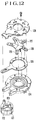
- a ring-shaped member 120 as shown in Fig. 12, for opening and closing the diaphragm blades in an interlocking relation.
- a lever 122 which is connected to the rotation shaft of a motor 121 is arranged to engage the diaphragm blades 125, 126 and 127 through the ring-shaped member 120.
- a cover plate 128 which is arranged to prevent the diaphragm blades from coming off the diaphragm unit and also to provide a sliding face for the diaphragm blades.
- the diaphragm blades 125, 126 and 127 cannot be smoothly turned (opened and closed), because a load for rotating the ring-shaped member 120 is large and because the amount of space in the direction of the plate thickness of the diaphragm blades 125 to 127 cannot be kept constant due to unevenness of the ring-shaped member 120 in the direction of the plate thickness thereof. Besides, a reduction in thickness and size of the device is limited by a space required for the ring-shaped member 120. The conventional arrangement thus has caused difficulty also in reducing the weight of the light-quantity control device.
- Another problem with the conventional arrangement lies in that the presence of the lever 122 in the path of driving force transmission to the diaphragm blades degrades the efficiency of the driving force transmission.
- a further problem lies in that the presence of the cover plate 128 increases a sliding resistance of the diaphragm blades.
- a still further problem lies in that these members require spaces for them and thus limits a possible reduction in thickness and size of the device. The presence of these members also makes a reduction in weight difficult.
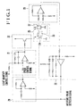
- Fig. 1 is a circuit diagram showing in outline the arrangement of the control part of a light-quantity control device which is arranged as a first embodiment of this invention.
- Fig. 2 is an exploded oblique view showing the light-quantity control device arranged as the first embodiment.
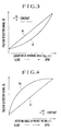
- Fig. 3 is a graph showing a position detection signal obtained with a rate of change of the area of an aperture assumed to be constant.
- Fig. 4 is a graph showing a position detection signal obtained with a rate of change of the angle of rotation of a magnet rotor assumed to be constant.
- Fig. 5 is a graph showing a speed control signal obtained with a rate of change per unit time of the area of an aperture assumed to be constant.
- Fig. 1 is a circuit diagram showing in outline the arrangement of the control part of a light-quantity control device which is arranged as a first embodiment of this invention.
- Fig. 2 is an exploded oblique view showing the light-quantity control device arranged as the first embodiment.
- Fig. 6 is a graph showing a speed control signal obtained with the rotating speed of a magnet rotor assumed to be constant.
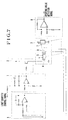
- Fig. 7 is a circuit diagram showing the essential arrangement of the control circuit of a light-quantity control device of the prior art.
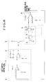
- Fig. 8 is a circuit diagram showing the essential arrangement of the control circuit of another light-quantity control device previously proposed.
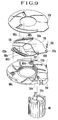
- Fig. 9 is an exploded oblique view showing a light-quantity control device arranged as a second embodiment of this invention.
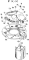
- Fig. 10 is an exploded oblique view showing a light-quantity control device arranged as a third embodiment of the invention.
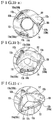
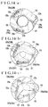
- FIG. 11(a), 11(b) and 11(c) show the action of the diaphragm blades of the light-quantity control device shown in Fig. 10.
- Fig. 12 is an exploded oblique view showing the light-quantity control device of the prior art.
- Fig. 13 is an exploded oblique view showing a light-quantity control device which is arranged as a fourth embodiment of the invention.
- Figs. 14(a), 14(b) and 14(c) show the action of the diaphragm blades of the light-quantity control device shown in Fig. 13.
- Fig. 1 is a circuit diagram showing in outline the arrangement of the control part of a light-quantity control device which is arranged as the first embodiment of this invention.
- a differential amplifier 21 is arranged to compare a light-quantity control signal with a speed control signal.
- a power amplifier 22 is arranged to make a speed error signal outputted from the differential amplifier 21 into a signal for driving a magnet rotor 25.
- a motor part 23 includes a driving coil 24, the magnet rotor 25 and a magnetic sensitive element 27 and is arranged to drive light-quantity control members 34 and 35 which will be described later herein.
- the driving coil 24 is arranged to cause the magnet rotor 25 to rotate according to the output signal of the power amplifier 22.
- the magnet rotor 25 is arranged to rotate for driving the light-quantity control members 34 and 35.
- the magnetic sensitive element 27 is arranged to linearly detect the position of the magnet rotor 25.
- a differential amplifier 28 is arranged to amplify and adjust the output of the magnetic sensitive element 27 to a given linear value.
- a differentiation circuit 29 is arranged to convert the linear output of a function generator 30 into the speed control signal.
- the function generator 30 is arranged to convert the position detection signal of the differential amplifier 28 which is in a linear form into a position detection signal having a rate of change proportional to a rate of change of the area of an aperture and to output the thus-converted position detection signal as an aperture-value detection signal.
- Fig. 2 shows in an exploded oblique view the above-stated light-quantity control device.
- a reference numeral 23 denotes the above-stated motor part.
- a diaphragm base plate 31 is arranged to carry the motor part 23 on one side thereof and to carry, on the other side, diaphragm blades 34 and 35 which are employed as the above-stated light-quantity control members.
- the base plate 31 has an aperture part.
- a driving arm 32 is arranged to transmit the driving force of the motor part 23 to the diaphragm blades 34 and 35.
- a spring 33 is arranged to constantly urge the diaphragm blades 34 and 35 to move in the direction of closing the diaphragm.
- the diaphragm blades 34 and 35 which are employed as the light-quantity control members control the quantity of light by making a sliding movement in such a way as to vary an amount of opening of the aperture.
- a cover 36 is arranged to house the diaphragm blades 34 and 35 and has an aperture part 37.
- the light-quantity control signal is first applied to the driving coil 24 via the differential amplifier 21 and the power amplifier 22.
- the driving coil 24 is energized to rotate the magnet rotor 25.
- the diaphragm blades 34 and 35 are driven by the rotation of the magnet rotor 25.
- the rotating position of the magnet rotor 25 is linearly detected by the magnetic sensitive element 27.
- the output signal of the magnetic sensitive element 27 is inputted via the differential amplifier 28 to the function generator 30 as a position detection signal in a given linear form.
- the function generator 30 converts the linear position detection signal into a linear position detection signal which is proportional to a rate of change of the area of the aperture as shown by a line V 0 in Fig. 3 or Fig. 4.
- the function generator 30 then outputs the thus-converted linear position detection signal as an aperture-value detection signal.
- the aperture-value detection signal which is linear relative to a rate of change of the area of the aperture is inputted to the differentiation circuit 29.
- the differentiation circuit 29 then outputs a speed control signal which is proportional to the inclination of the linear aperture-value detection signal. More specifically, the speed control signal is proportional to a rate of change per unit time of the area of the aperture, as shown by a line V 3 in Figs. 5 and 6.
- This speed control signal is inputted to the differential amplifier 21 to be compared with the light-quantity control signal.
- the differential amplifier 21 outputs a speed error signal which serves to prevent the light-quantity control signal from abruptly changing.
- the speed error signal passes through the power amplifier 22 to energize with current the driving coil 24.
- the driving coil 24 then causes the magnet rotor 25 to rotate.
- the rotation of the magnet rotor 25 drives the diaphragm blades 34 and 35 to speedily set the quantity of light at an apposite value.
- the function generator 30 and the differential amplifier 29 cause the speed control signal to be proportional to a rate of change per unit time of the area of the aperture and not proportional to the rotating speed of the magnet rotor 25.
- the speed control signal is an output which is proportional to a rate of change per unit time of the quantity of light which is the essential target for the control, so that speed control can be always appositely performed.
- Fig. 3 shows the position detection signal (the aperture-value detection signal) obtained when the diaphragm blades are moved from a closed position to a fully open position with a rate of change of the area of the aperture "ds/s" assumed to be constant.
- a line V 0 represents the aperture-value detection signal according to this embodiment of the invention.
- Another line V 1 represents an aperture-value detection signal obtained by the conventional device. The logarithm of the area of the aperture with "2" taken as a base thereof, which is shown on the axis of abscissa, makes a rate of change of the area of the aperture "ds/s" constant relative to equally spaced graduations. It is apparent from the illustration that the conventional position detection signal V 1 is improved to become the position detection signal V 0 of this embodiment having a rate of change proportional to a rate of change of the area of the aperture (having a constant inclination).
- Fig. 4 shows the position detection signal (the aperture-value detection signal) obtained with a rate of change of the angle of rotation of the magnet rotor "d ⁇ / ⁇ " assumed to be constant, in contrast to the case where a rate of change of the area of the aperture "ds/s" is assumed to be constant as shown in Fig. 3.
- the conventional aperture-value detection signal V 1 has a rate of change proportional to the rate of change of the angle of rotation "d ⁇ / ⁇ " (having a constant inclination).
- Fig. 5 shows the speed control signal obtained with a rate of change per unit time of the area of the aperture "ds/s ⁇ d/dt" assumed to be constant.
- a line V 3 represents the speed control signal according to this embodiment of the invention.
- Another line V 2 represents the conventional speed control signal.
- the conventional speed control signal V 2 is improved to become the speed control signal V 3 of this embodiment having a constant output where the rate of change per unit time of the area of the aperture "ds/s ⁇ d/dt" is assumed to be constant.
- Fig. 6 shows the speed control signal obtained with the speed of rotation of the magnet rotor "d ⁇ /dt" assumed to be constant, in contrast to the case where the rate of change ds/s ⁇ d/dt is assumed to be constant as shown in Fig. 5.
- the conventional speed control signal V 2 has a constant output where the speed of rotation of the magnet rotor "d ⁇ /dt" is constant.
- the first embodiment of this invention is arranged to perform speed control proportional to a rate of change per unit time of the area of the aperture.
- This arrangement enables the light-quantity control device to always adequately perform the speed control in relation to a change of the quantity of light. Therefore, the hunting which would occur at a stopped-down aperture (on the side of the minimum aperture) in the event of an excessive quantity of light can be minimized, and the response speed from the maximum aperture to the minimum aperture can be increased.
- the light-quantity control thus can be stably and speedily carried out with a high degree of accuracy.
- the accuracy of detecting an aperture value attainable on the side of the minimum aperture can be enhanced by means of the position detection signal which has a rate of change proportional to a rate of change of the area of the aperture.
- This arrangement contributes to the accuracy of automatic focusing performed by using aperture value information and also to the accuracy of aperture correction to be made by a so-called intelligent automatic iris device.
- the stability of control on the side of the minimum aperture in conjunction with the highly accurate aperture-value detection signal for a stopped-down aperture enables the manual stop to be accurately positioned on its minimum aperture side.
- a motor 101 serves as a drive source.
- a spring 103 is provided for returning diaphragm blades in the direction of closing them.
- a base plate 104 is provided for a diaphragm device.
- Diaphragm blades 105, 106 and 107 serve as light-quantity control members.
- a cover plate 108 is arranged to keep the diaphragm blades 105, 106 and 107 between it and the base plate 104.
- the rotation shaft 101a of the motor 101 is connected, by press fitting or the like, to a hole 105d which is provided in the dowel 105b of the diaphragm blade 105.
- the diaphragm blade 105 is arranged to be turnable (or swingable) on a hole 104a provided in the base plate 104.
- Other diaphragm blades 106 and 107 are respectively arranged to be turnable around dowels 106a and 107a which engage holes 104b and 104c provided in the base plate 104.
- each of the dowels 106b and 107b is provided with a stepped part which is arranged to secure a space required for preventing interference between the diaphragm blades 105 and 106 or between the diaphragm blades 106 and 107.
- the second embodiment described is arranged to obviate the necessity of use of any parts other than the diaphragm blades in opening and closing the diaphragm blades in an interlocking state.
- the driving force of the motor 101 can be transmitted with a minimal amount of loss to the diaphragm blades.
- the driving force thus can be efficiently transmitted.
- interference between the diaphragm blades can be minimized to lessen a working load on the diaphragm blades for a smooth operation.
- the efficiency of driving force transmission can be enhanced by the absence of the driving lever 122 which is included in the conventional device shown in Fig. 12.
- Fig. 10 shows a third embodiment of this invention.
- a motor 101 serves as a drive source.
- a spring 110 is arranged to return diaphragm blades in the direction of closing them.
- a base plate 109 is provided for a diaphragm device.
- Diaphragm blades 112, 113 and 114 are arranged to serve as light-quantity control members.
- Blade turning shafts 115 are provided for turning or swinging the diaphragm blades.
- the rotation shaft 101a of the motor 101 is connected, by press fitting or the like, to a hole 112d provided in the dowel 112b of the diaphragm blade 112.
- the diaphragm blade 112 is thus arranged to be turnable on a hole 109a provided in the base plate 109.
- the diaphragm blades 113 and 114 are respectively arranged to turn or swing around the parts 115b of the blade turning shafts 115 which engage holes 113a and 114a provided in the diaphragm blades 113 and 114.
- Parts 115a of the shafts 115 are connected, by press fitting or the like, to holes 109b and 109c provided in the base plate 109, respectively.
- the diaphragm blades 113 and 114 are rotatably held respectively at spaces provided between the base plate 109 and stepped parts 115c of the shafts 115.
- the diaphragm blade 112 which is connected to the shaft 101a of the motor 101 turns (opens or closes).
- the diaphragm blade 113 is caused to turn (open or close) by a dowel 113b which engages a cam-like slot 112c formed in the diaphragm blade 112.
- the diaphragm blade 114 is caused, also at the same time, to turn (open or close) by a dowel 114b which engages a cam-like slot 113c formed in the diaphragm blade 113.
- Figs. 11(a), 11(b) and 11(c) show the actions of the diaphragm blades 112, 113 and 114.
- each of the dowels 113b and 114b is provided with a stepped part which is arranged to prevent interference between the diaphragm blades 112 and 113 or between the diaphragm blades 113 and 114.
- Fig. 13 is an exploded oblique view showing a light-quantity control device which is arranged according to this invention as the fourth embodiment thereof.
- a motor 121 serves as a drive source.
- a lever 122 is provided for transmitting the driving force of the motor 121 to diaphragm blades.
- a spring 123 is provided for returning the diaphragm blades in the direction of closing them.
- a base plate 124 is provided for a diaphragm device. Diaphragm blades 125, 126 and 127 serve as light-quantity control members.
- a cover plate 128 is arranged to keep the diaphragm blades 125, 126 and 127 between it and the base plate 124.
- the diaphragm blade 125 is arranged to turn or swing on a hole 125b which engages a pin 124a provided on the base plate 124.
- Other diaphragm blades 126 and 127 are arranged to turn or swing on dowels 126a and 127a which engage holes 124b and 124c provided in the base plate 124, respectively.
- the diaphragm blade 126 is caused to turn (open or close) by a dowel 126b which engages a cam-like slot 125c formed in the diaphragm blade 125.
- the diaphragm blade 127 is caused to turn (open or close) by a dowel 127b which engages a cam-like slot 126c formed in the diaphragm blade 126.
- Figs. 14(a), 14(b) and 14(c) show the actions of the diaphragm blades 125, 126 and 127.
- each of the dowels 126b and 127b is provided with a stepped part which is arranged to secure a space for preventing interference between the diaphragm blades 125 and 126 or between the diaphragm blades 126 and 127.
- the arrangement of the embodiment shown in Fig. 13 requires no parts other than the diaphragm blades in opening and closing the diaphragm blades in an interlocking state. Therefore, the loss of the driving force of the motor 121 in transmitting the driving force to the diaphragm blades can be lessened for efficient driving force transmission. Further, the interference between the diaphragm blades can be lessened to reduce a working load on the diaphragm blades for a smooth operation.
- the return spring 123 is carried by a guide shaft 124e provided on the base plate 124 with one end of the return spring 123 connected to a spring engaging part 122b of the lever 122 and the other end to a spring engaging part 124d of the base plate 124.
- the fourth embodiment of the invention is, as apparent from the above description, arranged to have the return spring 123 mountable and dismountable in a unitized state.
- the return spring 123 is, therefore, replaceable without dismounting the motor 121, so that the working load can be easily adjusted.
- the coil part of the return spring 123 is disposed more outward than the outer diameter of a cylindrical part of the motor 121. Therefore, the position of the motor 121 in the axial direction of its cylindrical shape is shiftable toward the base plate 124 to an extent corresponding to the space of the coil part of the return spring 123. This arrangement permits a reduction in size of the device by minimizing the protruding amount of the motor 121.
Landscapes
- Physics & Mathematics (AREA)
- General Physics & Mathematics (AREA)
- Diaphragms For Cameras (AREA)
- Exposure Or Original Feeding In Electrophotography (AREA)
- Facsimile Scanning Arrangements (AREA)
- Endoscopes (AREA)
Description
- This invention relates to a light-quantity control device for use in a video camera or the like.
- Document US-4 470 679 discloses a central shutter for cameras, wherein a polygonal diaphragm is provided, the leaves of which can be actuated by means of a diaphragm actuator control curve cam. To this end, a plurality of diaphragm leaves is arranged in an interlocking state, each to be movable in accordance with a driving force of a diaphragm actuator being mounted rotatably on an annular projection provided concentrically to the shutter light passage. A coil spring is further used for biassing a setting lever with a certain tension.
- Moreover, document EP-A-0 388 139 discloses a light-quantity control device having a speed controller of a motor for adjusting a light amount control member of a camera, wherein a drive source information is used to control the rotational speed of the drive source. The amount of rotation of the rotor magnet of the motor is linearily detected and evaluated to obtain an output signal which serves as a control parameter for correcting the driving speed information. A correcting means provides a new driving speed information as the corrected value to the driving means.
- In detail, figures 7 or 8 refer to such a light-quantity control device.
- Fig. 7 shows in a circuit diagram the essential arrangement of the control circuit of the conventional light-quantity control device. Referring to Fig. 7, a
motor part 3 is arranged to drive a light-quantity control member. Themotor part 3 includes a driving coil 4 for causing a magnet,rotor 5 to rotate according to the output of apower amplifier 2 which is arranged to make into a motor driving signal a speed error signal output from adifferential amplifier 1 which is arranged to compare a light-quantity control signal with a speed control signal; themagnet rotor 5 which is arranged to move the light-quantity control member; adamping coil 6 which is arranged to detect the rotating speed of themagnet rotor 5; and a magneticsensitive element 7 which is arranged to detect the position of themagnet rotor 5. A signal output from thedamping coil 6 is input to thedifferential amplifier 1 as the speed control signal via asignal amplifier 9. A Linear position detection signal which is output from the magneticsensitive element 7 is converted into a linear aperture-value detection signal and output via adifferential amplifier 8. - Fig. 8 shows in a circuit diagram the essential arrangement of the control circuit of another light-quantity control device which has been proposed also in the past. In the device, a
motor part 13 is arranged to drive a light-quantity control member. Themotor part 13 includes a driving coil 14 for causing amagnet rotor 15 to rotate according to the output of apower amplifier 12 which is arranged to make into a motor driving signal a speed error signal output from a differential amplifier 11 which compares a light-quantity control signal with a speed control signal; themagnet rotor 15 which is arranged to move the light quantity control member; and a magnetic sensitive element 17 which is arranged to detect the position of themagnet rotor 15. A linear position detection signal which is output from the magnetic sensitive element 17 is converted into a linear aperture-value detection signal and is output via adifferential amplifier 18. Further, the linear aperture-value detection signal is converted into a speed control signal by adifferentiation circuit 19. The speed control signal is inputted to the differential amplifier 11. - In each of the conventional devices described, the speed control signal is an output proportional to the rotating speed of the magnet rotor but not proportional to a rate of change per unit time of the area of an aperture (aperture value). Although speed control thus can be performed with a constant strength in relation to the rotating speed of the magnet rotor, the speed control is not uniformly performed in relation to a rate of change per unit time of the quantity of light which is an essential target for the control. In other words, with respect to a change of the quantity of light, an action of the light-quantity control member becomes too slow at a large aperture (on the side of a maximum aperture) and too fast at a small aperture (on the side of a minimum aperture) under the above-stated conventional speed control. Under such a control, hunting tends to take place on the side of a minimum aperture in the event of an excessive quantity of light and, moreover, the response time of the light-quantity control member becomes too slow in shifting the aperture from a maximum position to a minimum position.
- Further, in the case of the conventional device, the aperture-value detection signal is a linear position detection signal which is in proportion to the amount of driving of the magnet rotor but not in proportion to a rate of change of the area of an aperture. The accuracy of detecting an aperture value, therefore, excessively degrades on the side of the minimum aperture.
- In a case where a diaphragm device of a video camera or the like is in a circular shape having at least three blades, it has been necessary to employ a ring-
shaped member 120, as shown in Fig. 12, for opening and closing the diaphragm blades in an interlocking relation. Alever 122 which is connected to the rotation shaft of amotor 121 is arranged to engage thediaphragm blades member 120. Further, there is provided acover plate 128 which is arranged to prevent the diaphragm blades from coming off the diaphragm unit and also to provide a sliding face for the diaphragm blades. - In accordance with the above-stated conventional arrangement, however, the
diaphragm blades shaped member 120 is large and because the amount of space in the direction of the plate thickness of thediaphragm blades 125 to 127 cannot be kept constant due to unevenness of the ring-shaped member 120 in the direction of the plate thickness thereof. Besides, a reduction in thickness and size of the device is limited by a space required for the ring-shaped member 120. The conventional arrangement thus has caused difficulty also in reducing the weight of the light-quantity control device. - In addition to these problems, another problem with the conventional arrangement lies in that the presence of the
lever 122 in the path of driving force transmission to the diaphragm blades degrades the efficiency of the driving force transmission. A further problem lies in that the presence of thecover plate 128 increases a sliding resistance of the diaphragm blades. A still further problem lies in that these members require spaces for them and thus limits a possible reduction in thickness and size of the device. The presence of these members also makes a reduction in weight difficult. - Other conventional light-quantity control devices are disclosed in JP-A-63294540 and US-A-3 984 847.
- It is one aspect of the invention to provide a light-quantity control device as defined in
claim 1 which is capable of performing speed control always apposite to a rate of change in the quantity of light by virtue of speed control means arranged in the device to perform the speed control in proportion to a rate of change per unit time of the area of the device aperture. - It is another aspect of the invention to provide a light-quantity control device which has the rotation shaft of a driving part connected to a central rotation shaft of a diaphragm blade in such a way as to allow the rotary motion of the driving part to be directly converted into the rotary motion of the diaphragm blade, so that the diaphragm blade can be driven with a small driving force.
- It is a still further aspect of the invention to provide a light-quantity control device which permits a reduction in size and weight thereof by virtue of the arrangement thereof, wherein a plurality of diaphragm blades are interconnected through projections and cam-like slots which are formed on and in the diaphragm blades and arranged to engage each other in such a manner that a driving force which is transmitted to a specific diaphragm blade is transmitted also to other diaphragm blades.
- These and other aspect and features of the invention will become apparent from the following detailed description of embodiments thereof taken in connection with the accompanying drawings.
- Fig. 1 is a circuit diagram showing in outline the arrangement of the control part of a light-quantity control device which is arranged as a first embodiment of this invention. Fig. 2 is an exploded oblique view showing the light-quantity control device arranged as the first embodiment. Fig. 3 is a graph showing a position detection signal obtained with a rate of change of the area of an aperture assumed to be constant. Fig. 4 is a graph showing a position detection signal obtained with a rate of change of the angle of rotation of a magnet rotor assumed to be constant. Fig. 5 is a graph showing a speed control signal obtained with a rate of change per unit time of the area of an aperture assumed to be constant. Fig. 6 is a graph showing a speed control signal obtained with the rotating speed of a magnet rotor assumed to be constant. Fig. 7 is a circuit diagram showing the essential arrangement of the control circuit of a light-quantity control device of the prior art. Fig. 8 is a circuit diagram showing the essential arrangement of the control circuit of another light-quantity control device previously proposed. Fig. 9 is an exploded oblique view showing a light-quantity control device arranged as a second embodiment of this invention. Fig. 10 is an exploded oblique view showing a light-quantity control device arranged as a third embodiment of the invention. Figs. 11(a), 11(b) and 11(c) show the action of the diaphragm blades of the light-quantity control device shown in Fig. 10. Fig. 12 is an exploded oblique view showing the light-quantity control device of the prior art. Fig. 13 is an exploded oblique view showing a light-quantity control device which is arranged as a fourth embodiment of the invention. Figs. 14(a), 14(b) and 14(c) show the action of the diaphragm blades of the light-quantity control device shown in Fig. 13.
- A first embodiment of this invention is described with reference to Figs. 1 to 6 as follows:
- Fig. 1 is a circuit diagram showing in outline the arrangement of the control part of a light-quantity control device which is arranged as the first embodiment of this invention. Referring to Fig. 1, a
differential amplifier 21 is arranged to compare a light-quantity control signal with a speed control signal. Apower amplifier 22 is arranged to make a speed error signal outputted from thedifferential amplifier 21 into a signal for driving amagnet rotor 25. Amotor part 23 includes a driving coil 24, themagnet rotor 25 and a magneticsensitive element 27 and is arranged to drive light-quantity control members magnet rotor 25 to rotate according to the output signal of thepower amplifier 22. Themagnet rotor 25 is arranged to rotate for driving the light-quantity control members sensitive element 27 is arranged to linearly detect the position of themagnet rotor 25. Adifferential amplifier 28 is arranged to amplify and adjust the output of the magneticsensitive element 27 to a given linear value. Adifferentiation circuit 29 is arranged to convert the linear output of afunction generator 30 into the speed control signal. Thefunction generator 30 is arranged to convert the position detection signal of thedifferential amplifier 28 which is in a linear form into a position detection signal having a rate of change proportional to a rate of change of the area of an aperture and to output the thus-converted position detection signal as an aperture-value detection signal. - Fig. 2 shows in an exploded oblique view the above-stated light-quantity control device. In Fig. 2, a
reference numeral 23 denotes the above-stated motor part. Adiaphragm base plate 31 is arranged to carry themotor part 23 on one side thereof and to carry, on the other side,diaphragm blades base plate 31 has an aperture part. A drivingarm 32 is arranged to transmit the driving force of themotor part 23 to thediaphragm blades spring 33 is arranged to constantly urge thediaphragm blades diaphragm blades cover 36 is arranged to house thediaphragm blades aperture part 37. - With the embodiment arranged as described above, the light-quantity control signal is first applied to the driving coil 24 via the
differential amplifier 21 and thepower amplifier 22. As a result, the driving coil 24 is energized to rotate themagnet rotor 25. Thediaphragm blades magnet rotor 25. The rotating position of themagnet rotor 25 is linearly detected by the magneticsensitive element 27. The output signal of the magneticsensitive element 27 is inputted via thedifferential amplifier 28 to thefunction generator 30 as a position detection signal in a given linear form. Thefunction generator 30 converts the linear position detection signal into a linear position detection signal which is proportional to a rate of change of the area of the aperture as shown by a line V0 in Fig. 3 or Fig. 4. Thefunction generator 30 then outputs the thus-converted linear position detection signal as an aperture-value detection signal. - The aperture-value detection signal which is linear relative to a rate of change of the area of the aperture is inputted to the
differentiation circuit 29. Thedifferentiation circuit 29 then outputs a speed control signal which is proportional to the inclination of the linear aperture-value detection signal. More specifically, the speed control signal is proportional to a rate of change per unit time of the area of the aperture, as shown by a line V3 in Figs. 5 and 6. This speed control signal is inputted to thedifferential amplifier 21 to be compared with the light-quantity control signal. As a result, thedifferential amplifier 21 outputs a speed error signal which serves to prevent the light-quantity control signal from abruptly changing. The speed error signal passes through thepower amplifier 22 to energize with current the driving coil 24. The driving coil 24 then causes themagnet rotor 25 to rotate. The rotation of themagnet rotor 25 drives thediaphragm blades function generator 30 and thedifferential amplifier 29 cause the speed control signal to be proportional to a rate of change per unit time of the area of the aperture and not proportional to the rotating speed of themagnet rotor 25. In other words, the speed control signal is an output which is proportional to a rate of change per unit time of the quantity of light which is the essential target for the control, so that speed control can be always appositely performed. - Fig. 3 shows the position detection signal (the aperture-value detection signal) obtained when the diaphragm blades are moved from a closed position to a fully open position with a rate of change of the area of the aperture "ds/s" assumed to be constant. In Fig. 3, a line V0 represents the aperture-value detection signal according to this embodiment of the invention. Another line V1 represents an aperture-value detection signal obtained by the conventional device. The logarithm of the area of the aperture with "2" taken as a base thereof, which is shown on the axis of abscissa, makes a rate of change of the area of the aperture "ds/s" constant relative to equally spaced graduations. It is apparent from the illustration that the conventional position detection signal V1 is improved to become the position detection signal V0 of this embodiment having a rate of change proportional to a rate of change of the area of the aperture (having a constant inclination).
- Fig. 4 shows the position detection signal (the aperture-value detection signal) obtained with a rate of change of the angle of rotation of the magnet rotor "d/" assumed to be constant, in contrast to the case where a rate of change of the area of the aperture "ds/s" is assumed to be constant as shown in Fig. 3. As apparent from Fig. 4, the conventional aperture-value detection signal V1 has a rate of change proportional to the rate of change of the angle of rotation "d/" (having a constant inclination).
- Fig. 5 shows the speed control signal obtained with a rate of change per unit time of the area of the aperture "ds/s·d/dt" assumed to be constant. In Fig. 5, a line V3 represents the speed control signal according to this embodiment of the invention. Another line V2 represents the conventional speed control signal. As apparent from Fig. 5, the conventional speed control signal V2 is improved to become the speed control signal V3 of this embodiment having a constant output where the rate of change per unit time of the area of the aperture "ds/s·d/dt" is assumed to be constant.
- Fig. 6 shows the speed control signal obtained with the speed of rotation of the magnet rotor "d/dt" assumed to be constant, in contrast to the case where the rate of change ds/s·d/dt is assumed to be constant as shown in Fig. 5. As apparent from Fig. 6, the conventional speed control signal V2 has a constant output where the speed of rotation of the magnet rotor "d/dt" is constant.
- As described above, the first embodiment of this invention is arranged to perform speed control proportional to a rate of change per unit time of the area of the aperture. This arrangement enables the light-quantity control device to always adequately perform the speed control in relation to a change of the quantity of light. Therefore, the hunting which would occur at a stopped-down aperture (on the side of the minimum aperture) in the event of an excessive quantity of light can be minimized, and the response speed from the maximum aperture to the minimum aperture can be increased. The light-quantity control thus can be stably and speedily carried out with a high degree of accuracy.
- Further, the accuracy of detecting an aperture value attainable on the side of the minimum aperture can be enhanced by means of the position detection signal which has a rate of change proportional to a rate of change of the area of the aperture. This arrangement contributes to the accuracy of automatic focusing performed by using aperture value information and also to the accuracy of aperture correction to be made by a so-called intelligent automatic iris device. In the case of a manual stop, the stability of control on the side of the minimum aperture in conjunction with the highly accurate aperture-value detection signal for a stopped-down aperture enables the manual stop to be accurately positioned on its minimum aperture side.
- Next, a light-quantity control device which is arranged according to this invention as a second embodiment thereof is described below with reference to Fig. 9:
- Referring to Fig. 9, a
motor 101 serves as a drive source. Aspring 103 is provided for returning diaphragm blades in the direction of closing them. Abase plate 104 is provided for a diaphragm device.Diaphragm blades cover plate 108 is arranged to keep thediaphragm blades base plate 104. - The
rotation shaft 101a of themotor 101 is connected, by press fitting or the like, to ahole 105d which is provided in thedowel 105b of thediaphragm blade 105. Thediaphragm blade 105 is arranged to be turnable (or swingable) on ahole 104a provided in thebase plate 104.Other diaphragm blades dowels holes base plate 104. When theshaft 101a of themotor 101 makes a reciprocating turning motion, thediaphragm blade 105 which is connected to theshaft 101a of themotor 101 turns (opens or closes). At the same time, thediaphragm blade 106 is caused to turn (open or close) by thedowel 106b which engages a cam-like slot 105c formed in thediaphragm blade 105. Further, at the same time, thediaphragm blade 107 is caused to turn (open or close) by thedowel 107b which engages a cam-like slot 106c formed in thediaphragm blade 106. Incidentally, each of thedowels diaphragm blades diaphragm blades - The second embodiment described is arranged to obviate the necessity of use of any parts other than the diaphragm blades in opening and closing the diaphragm blades in an interlocking state. The driving force of the
motor 101 can be transmitted with a minimal amount of loss to the diaphragm blades. The driving force thus can be efficiently transmitted. Further, interference between the diaphragm blades can be minimized to lessen a working load on the diaphragm blades for a smooth operation. The efficiency of driving force transmission can be enhanced by the absence of the drivinglever 122 which is included in the conventional device shown in Fig. 12. - Fig. 10 shows a third embodiment of this invention. Referring to Fig. 10, a
motor 101 serves as a drive source. Aspring 110 is arranged to return diaphragm blades in the direction of closing them. Abase plate 109 is provided for a diaphragm device.Diaphragm blades Blade turning shafts 115 are provided for turning or swinging the diaphragm blades. Therotation shaft 101a of themotor 101 is connected, by press fitting or the like, to ahole 112d provided in thedowel 112b of thediaphragm blade 112. Thediaphragm blade 112 is thus arranged to be turnable on ahole 109a provided in thebase plate 109. Thediaphragm blades parts 115b of theblade turning shafts 115 which engageholes diaphragm blades Parts 115a of theshafts 115 are connected, by press fitting or the like, toholes base plate 109, respectively. Thediaphragm blades base plate 109 and steppedparts 115c of theshafts 115. - When the
motor 101 makes a reciprocating turning motion, thediaphragm blade 112 which is connected to theshaft 101a of themotor 101 turns (opens or closes). At the same time, thediaphragm blade 113 is caused to turn (open or close) by adowel 113b which engages a cam-like slot 112c formed in thediaphragm blade 112. Thediaphragm blade 114 is caused, also at the same time, to turn (open or close) by adowel 114b which engages a cam-like slot 113c formed in thediaphragm blade 113. Figs. 11(a), 11(b) and 11(c) show the actions of thediaphragm blades dowels diaphragm blades diaphragm blades - The second and third embodiments described above give the following advantages:
- (1) No parts other than the diaphragm blades are necessary for opening and closing the diaphragm blades in an interlocking state. The loss of the driving force of the motor in transmitting to the driving force to the diaphragm blades can be lessened, so that the driving force transmission can be efficiently carried out.
- (2) Interference between diaphragm blades can be minimized. Therefore, the working load on the diaphragm blades can be lessened for a smooth operation.
- (3) The absence of the
member 120, the drivinglever 122 and thecover plate 128 shown in Fig. 12 enhances the efficiency of driving force transmission. -
- A fourth embodiment of the invention is described below with reference to Figs. 13, 14(a), 14(b) and 14(c):
- Fig. 13 is an exploded oblique view showing a light-quantity control device which is arranged according to this invention as the fourth embodiment thereof. Referring to Fig. 13, a
motor 121 serves as a drive source. Alever 122 is provided for transmitting the driving force of themotor 121 to diaphragm blades. Aspring 123 is provided for returning the diaphragm blades in the direction of closing them. Abase plate 124 is provided for a diaphragm device.Diaphragm blades cover plate 128 is arranged to keep thediaphragm blades base plate 124. - The
diaphragm blade 125 is arranged to turn or swing on ahole 125b which engages apin 124a provided on thebase plate 124.Other diaphragm blades dowels holes base plate 124, respectively. When the shaft of themotor 121 makes a reciprocating turning motion, thelever 122 turns. Thediaphragm blade 125 is then caused to turn (open or close) jointly by apin 122a provided on thelever 122 and ahole 125a formed in thediaphragm blade 125. At the same time, thediaphragm blade 126 is caused to turn (open or close) by adowel 126b which engages a cam-like slot 125c formed in thediaphragm blade 125. Further, at the same time, thediaphragm blade 127 is caused to turn (open or close) by adowel 127b which engages a cam-like slot 126c formed in thediaphragm blade 126. Figs. 14(a), 14(b) and 14(c) show the actions of thediaphragm blades dowels diaphragm blades diaphragm blades - The arrangement of the embodiment shown in Fig. 13 requires no parts other than the diaphragm blades in opening and closing the diaphragm blades in an interlocking state. Therefore, the loss of the driving force of the
motor 121 in transmitting the driving force to the diaphragm blades can be lessened for efficient driving force transmission. Further, the interference between the diaphragm blades can be lessened to reduce a working load on the diaphragm blades for a smooth operation. - Further, the
return spring 123 is carried by a guide shaft 124e provided on thebase plate 124 with one end of thereturn spring 123 connected to a spring engaging part 122b of thelever 122 and the other end to aspring engaging part 124d of thebase plate 124. - The fourth embodiment of the invention is, as apparent from the above description, arranged to have the
return spring 123 mountable and dismountable in a unitized state. Thereturn spring 123 is, therefore, replaceable without dismounting themotor 121, so that the working load can be easily adjusted. Further, the coil part of thereturn spring 123 is disposed more outward than the outer diameter of a cylindrical part of themotor 121. Therefore, the position of themotor 121 in the axial direction of its cylindrical shape is shiftable toward thebase plate 124 to an extent corresponding to the space of the coil part of thereturn spring 123. This arrangement permits a reduction in size of the device by minimizing the protruding amount of themotor 121.
Claims (8)
- A light-quantity control device comprising:characterized in thata) a drive source (101);b) a plurality of light-quantity control members (105, 106, 107) arranged to be moved by said drive source (101), said light-quantity control members having a shape defining an aperture which varies according to the movement of said light-quantity control members (105, 106, 107);
c) said plurality of light-quantity control members comprises a first light-quantity control member being movable by said drive source (101) and a second light-quantity control member connected to said first light-quantity control member so as to be movable by the movement of said first light-quantity control member. - A device according to claim 1, characterized in that a swinging force is applied by a rotatory output of said drive source (101) at the center of swing of said first light-quantity control member.
- A device according to claim 1, characterized in that a swinging force is applied by a rotatory output of said drive source (101) at a point deviating from the center of swing of said first light-quantity control member.
- A device according to claims 2 and 3, characterized in that said plurality of light-quantity control members are interconnected by slots in said members and projections from said members which are inserted into the slots, and wherein the amount of opening of said aperture is varied by the interlocking swinging of said plurality of light-quantity control member when said first light-quantity control member is driven to be swung by said drive source (101).
- A device according to claim 2,
characterized in that said first light-quantity control member is directly secured to an output shaft of said drive source (101). - A device according to claim 3,
characterized in that said first light-quantity control member is arranged to be swung by a lever (122) which is secured to an output shaft of said drive source (101). - A device according to claim 4,
characterized in that said projections have diameters mutually different, each of which is arranged in such a way as to give some clearance between faces of said light-quantity control members when said light-quantity control members overlap each other. - A device according to claim 4,
characterized in that a motor is employed as said drive source (101), wherein rotation of an output shaft of said motor is transmitted to a lever (122), and wherein said first light-quantity control member is swung by said lever.
Applications Claiming Priority (13)
| Application Number | Priority Date | Filing Date | Title |
|---|---|---|---|
| JP2419082A JP2571982B2 (en) | 1990-12-25 | 1990-12-25 | Light amount control device and optical apparatus having light amount control device |
| JP41908290 | 1990-12-25 | ||
| JP419082/90 | 1990-12-25 | ||
| JP12132491 | 1991-05-27 | ||
| JP12132591 | 1991-05-27 | ||
| JP12132391 | 1991-05-27 | ||
| JP121325/91 | 1991-05-27 | ||
| JP3121323A JP2765768B2 (en) | 1991-05-27 | 1991-05-27 | Light control device |
| JP12132491A JPH05232542A (en) | 1991-05-27 | 1991-05-27 | Light quantity controller |
| JP121324/91 | 1991-05-27 | ||
| JP3121325A JP2765769B2 (en) | 1991-05-27 | 1991-05-27 | Light control device |
| JP121323/91 | 1991-05-27 | ||
| EP91122211A EP0492617B1 (en) | 1990-12-25 | 1991-12-24 | Light-quantity control device |
Related Parent Applications (2)
| Application Number | Title | Priority Date | Filing Date |
|---|---|---|---|
| EP91122211.5 Division | 1991-12-24 | ||
| EP91122211A Division EP0492617B1 (en) | 1990-12-25 | 1991-12-24 | Light-quantity control device |
Publications (3)
| Publication Number | Publication Date |
|---|---|
| EP0708358A2 EP0708358A2 (en) | 1996-04-24 |
| EP0708358A3 EP0708358A3 (en) | 1997-06-04 |
| EP0708358B1 true EP0708358B1 (en) | 2000-03-22 |
Family
ID=27470770
Family Applications (2)
| Application Number | Title | Priority Date | Filing Date |
|---|---|---|---|
| EP91122211A Expired - Lifetime EP0492617B1 (en) | 1990-12-25 | 1991-12-24 | Light-quantity control device |
| EP95118783A Expired - Lifetime EP0708358B1 (en) | 1990-12-25 | 1991-12-24 | Light-quantity control device |
Family Applications Before (1)
| Application Number | Title | Priority Date | Filing Date |
|---|---|---|---|
| EP91122211A Expired - Lifetime EP0492617B1 (en) | 1990-12-25 | 1991-12-24 | Light-quantity control device |
Country Status (4)
| Country | Link |
|---|---|
| US (3) | US5646769A (en) |
| EP (2) | EP0492617B1 (en) |
| CA (1) | CA2058396C (en) |
| DE (2) | DE69131039T2 (en) |
Families Citing this family (23)
| Publication number | Priority date | Publication date | Assignee | Title |
|---|---|---|---|---|
| JP2746509B2 (en) * | 1992-12-09 | 1998-05-06 | キヤノン電子株式会社 | Light control device |
| US5414460A (en) * | 1993-06-08 | 1995-05-09 | Eastman Kodak Company | Mechanical aperture for controlling illumination level |
| US6325554B1 (en) | 2000-03-15 | 2001-12-04 | Eastman Kodak Company | Camera with electrostatic light valve that functions as image reflecting mirror for viewfinder |
| US6443637B1 (en) | 2000-03-15 | 2002-09-03 | Eastman Kodak Company | Camera with electrostatic light valve that functions as diaphragm |
| JP3802870B2 (en) * | 2002-12-20 | 2006-07-26 | 株式会社タムロン | Light control device |
| US7394497B2 (en) * | 2003-03-27 | 2008-07-01 | Fujifilm Corporation | Camera with variable aperture member |
| JP4540322B2 (en) * | 2003-09-29 | 2010-09-08 | Hoya株式会社 | Inter-image corresponding point detection apparatus and inter-image corresponding point detection method |
| KR101281445B1 (en) | 2003-10-29 | 2013-07-02 | 칼 짜이스 에스엠테 게엠베하 | Diaphragm changing device |
| JP4250516B2 (en) * | 2003-12-08 | 2009-04-08 | キヤノン株式会社 | Light amount adjusting device, optical device and photographing device |
| US20050226612A1 (en) * | 2004-04-08 | 2005-10-13 | Asia Optical Co., Inc. | Automatic diaphragm assembly with a variable aperture for a lens |
| US7553094B2 (en) * | 2004-07-01 | 2009-06-30 | Canon Kabushiki Kaisha | Light quantity adjusting apparatus, image pickup apparatus and optical apparatus |
| JP2006018019A (en) * | 2004-07-01 | 2006-01-19 | Canon Inc | Light amount adjusting device, imaging device, and optical device |
| JP3983235B2 (en) * | 2004-08-20 | 2007-09-26 | ニスカ株式会社 | Light intensity adjustment device |
| KR100933294B1 (en) | 2007-11-29 | 2009-12-22 | 삼성전자주식회사 | Shutter and micro camera module having same |
| JP5373433B2 (en) * | 2009-02-27 | 2013-12-18 | 日本電産コパル株式会社 | Camera aperture device |
| KR20110081700A (en) * | 2010-01-08 | 2011-07-14 | 삼성전자주식회사 | Light shielding device and manufacturing method thereof |
| TWI468848B (en) * | 2010-03-04 | 2015-01-11 | Hon Hai Prec Ind Co Ltd | Mechanical shutter and portable electronic device with same |
| CN102193272B (en) * | 2010-03-05 | 2015-09-09 | 鸿富锦精密工业(深圳)有限公司 | Mechanical shutter and adopt the portable electron device of this mechanical shutter |
| KR20120068569A (en) | 2010-12-17 | 2012-06-27 | 삼성전자주식회사 | Light screening apparatus and electronic device including the same |
| KR101878719B1 (en) | 2011-06-24 | 2018-07-16 | 삼성전자 주식회사 | Light screening apparatus and its fabricating method |
| JP6172955B2 (en) * | 2013-01-30 | 2017-08-02 | キヤノン株式会社 | Light amount adjusting device, lens barrel and imaging device |
| US9134588B2 (en) * | 2013-08-08 | 2015-09-15 | Canon Kabushiki Kaisha | Stop apparatus, and lens apparatus and image pickup apparatus having the same |
| TWI648590B (en) * | 2017-07-13 | 2019-01-21 | 致能機電工業股份有限公司 | Mobile device with variable aperture function |
Family Cites Families (14)
| Publication number | Priority date | Publication date | Assignee | Title |
|---|---|---|---|---|
| US3984847A (en) * | 1973-09-29 | 1976-10-05 | Olympus Optical Co., Ltd. | Electric eye exposure apparatus for use in a camera having a bladed shutter mechanism |
| US4335947A (en) * | 1979-11-21 | 1982-06-22 | Balda-Werke Photographische Gerate Und Kunststoff Gmbh & Co., Kg | Camera shutter assembly |
| JPS5919471A (en) * | 1982-07-24 | 1984-01-31 | Asahi Optical Co Ltd | Iris control circuit of video camera |
| US4470679A (en) | 1983-02-03 | 1984-09-11 | Franz Starp | Central shutter for cameras, especially professional cameras |
| US5134435A (en) * | 1985-04-25 | 1992-07-28 | Canon Kabushiki Kaisha | Camera |
| US4716432A (en) * | 1986-04-24 | 1987-12-29 | Eastman Kodak Company | Exposure control apparatus |
| JPS62188744U (en) * | 1986-05-21 | 1987-12-01 | ||
| US4862207A (en) * | 1987-05-21 | 1989-08-29 | Olympus Optical Company Limited | Diaphragm apparatus for camera |
| JP2563334B2 (en) * | 1987-05-27 | 1996-12-11 | オリンパス光学工業株式会社 | Aperture mechanism |
| JPH02156233A (en) * | 1988-12-08 | 1990-06-15 | Nikon Corp | Squeezing device |
| JPH02239782A (en) | 1989-03-14 | 1990-09-21 | Canon Electron Inc | Luminous quantity controller |
| US5313244A (en) * | 1989-06-28 | 1994-05-17 | Asahi Kogaku Kogyo Kabushiki Kaisha | Camera |
| US5115261A (en) * | 1989-07-25 | 1992-05-19 | Asahi Kogaku Kogyo Kabushiki Kaisha | Photographing light quantity controller for endoscope |
| US4978991A (en) * | 1989-12-29 | 1990-12-18 | Polaroid Corporation | Open-loop stepper motor controlled shutter |
-
1991
- 1991-12-23 CA CA002058396A patent/CA2058396C/en not_active Expired - Lifetime
- 1991-12-24 EP EP91122211A patent/EP0492617B1/en not_active Expired - Lifetime
- 1991-12-24 DE DE69131039T patent/DE69131039T2/en not_active Expired - Lifetime
- 1991-12-24 EP EP95118783A patent/EP0708358B1/en not_active Expired - Lifetime
- 1991-12-24 DE DE69132075T patent/DE69132075T2/en not_active Expired - Fee Related
-
1995
- 1995-03-24 US US08/409,541 patent/US5646769A/en not_active Expired - Lifetime
- 1995-04-06 US US08/417,829 patent/US5749015A/en not_active Expired - Lifetime
- 1995-04-06 US US08/417,826 patent/US5646770A/en not_active Expired - Lifetime
Also Published As
| Publication number | Publication date |
|---|---|
| DE69132075D1 (en) | 2000-04-27 |
| US5646769A (en) | 1997-07-08 |
| DE69132075T2 (en) | 2000-09-14 |
| US5646770A (en) | 1997-07-08 |
| EP0492617B1 (en) | 1999-03-24 |
| EP0492617A2 (en) | 1992-07-01 |
| CA2058396C (en) | 1995-05-30 |
| DE69131039D1 (en) | 1999-04-29 |
| CA2058396A1 (en) | 1992-06-26 |
| EP0492617A3 (en) | 1993-05-26 |
| DE69131039T2 (en) | 1999-10-21 |
| EP0708358A3 (en) | 1997-06-04 |
| EP0708358A2 (en) | 1996-04-24 |
| US5749015A (en) | 1998-05-05 |
Similar Documents
| Publication | Publication Date | Title |
|---|---|---|
| EP0492617B1 (en) | Light-quantity control device | |
| KR100229112B1 (en) | Aperture Control Method and Aperture Driving Device | |
| US6350068B1 (en) | Quantity-of-light adjusting device and optical apparatus having the same | |
| US4975725A (en) | Aperture and focus adjusting device for a camera | |
| US5237357A (en) | Aperture and focus adjusting device for a camera | |
| US5117137A (en) | Stepping motor for use in a camera with multiple shutters | |
| US4918480A (en) | Electromagnetic shutter for camera | |
| US4731626A (en) | Diaphragm device for camera | |
| EP0520912B1 (en) | Iris drive mechanism | |
| JP3723645B2 (en) | Method and apparatus for adjusting aperture origin of aperture mechanism | |
| US4636041A (en) | Aperture device for zoom lens | |
| US5138355A (en) | Aperture and focus adjusting device for a camera | |
| US6535691B1 (en) | Lens drive and lens shutter unit | |
| US4614416A (en) | Operation control device for camera | |
| JPH02254431A (en) | Camera with aperture diameter regulating device | |
| JP2614351B2 (en) | Light amount control device having position detecting device | |
| JPS6020105Y2 (en) | Camera light aperture device | |
| JP3110179B2 (en) | Signal detection device for camera shutter | |
| JPH0641224Y2 (en) | A diaphragm device driven by a motor | |
| JP3192043B2 (en) | Exposure control device | |
| JPH07319005A (en) | Light control device | |
| JPS59219074A (en) | Aperture device of video camera | |
| JPH05257057A (en) | Mobile diaphragm mechanism | |
| JP2000352657A (en) | Zoom lens | |
| JP2515029Y2 (en) | Camera shutter device |
Legal Events
| Date | Code | Title | Description |
|---|---|---|---|
| PUAI | Public reference made under article 153(3) epc to a published international application that has entered the european phase |
Free format text: ORIGINAL CODE: 0009012 |
|
| AC | Divisional application: reference to earlier application |
Ref document number: 492617 Country of ref document: EP |
|
| AK | Designated contracting states |
Kind code of ref document: A2 Designated state(s): DE FR GB NL |
|
| PUAL | Search report despatched |
Free format text: ORIGINAL CODE: 0009013 |
|
| AK | Designated contracting states |
Kind code of ref document: A3 Designated state(s): DE FR GB NL |
|
| 17P | Request for examination filed |
Effective date: 19971118 |
|
| GRAG | Despatch of communication of intention to grant |
Free format text: ORIGINAL CODE: EPIDOS AGRA |
|
| 17Q | First examination report despatched |
Effective date: 19990406 |
|
| GRAG | Despatch of communication of intention to grant |
Free format text: ORIGINAL CODE: EPIDOS AGRA |
|
| GRAH | Despatch of communication of intention to grant a patent |
Free format text: ORIGINAL CODE: EPIDOS IGRA |
|
| GRAH | Despatch of communication of intention to grant a patent |
Free format text: ORIGINAL CODE: EPIDOS IGRA |
|
| GRAA | (expected) grant |
Free format text: ORIGINAL CODE: 0009210 |
|
| AC | Divisional application: reference to earlier application |
Ref document number: 492617 Country of ref document: EP |
|
| AK | Designated contracting states |
Kind code of ref document: B1 Designated state(s): DE FR GB NL |
|
| PG25 | Lapsed in a contracting state [announced via postgrant information from national office to epo] |
Ref country code: NL Free format text: LAPSE BECAUSE OF FAILURE TO SUBMIT A TRANSLATION OF THE DESCRIPTION OR TO PAY THE FEE WITHIN THE PRESCRIBED TIME-LIMIT Effective date: 20000322 Ref country code: FR Free format text: LAPSE BECAUSE OF FAILURE TO SUBMIT A TRANSLATION OF THE DESCRIPTION OR TO PAY THE FEE WITHIN THE PRESCRIBED TIME-LIMIT Effective date: 20000322 |
|
| REF | Corresponds to: |
Ref document number: 69132075 Country of ref document: DE Date of ref document: 20000427 |
|
| EN | Fr: translation not filed | ||
| NLV1 | Nl: lapsed or annulled due to failure to fulfill the requirements of art. 29p and 29m of the patents act | ||
| PLBE | No opposition filed within time limit |
Free format text: ORIGINAL CODE: 0009261 |
|
| STAA | Information on the status of an ep patent application or granted ep patent |
Free format text: STATUS: NO OPPOSITION FILED WITHIN TIME LIMIT |
|
| 26N | No opposition filed | ||
| PG25 | Lapsed in a contracting state [announced via postgrant information from national office to epo] |
Ref country code: DE Free format text: LAPSE BECAUSE OF NON-PAYMENT OF DUE FEES Effective date: 20011002 |
|
| REG | Reference to a national code |
Ref country code: GB Ref legal event code: IF02 |
|
| PGFP | Annual fee paid to national office [announced via postgrant information from national office to epo] |
Ref country code: GB Payment date: 20101222 Year of fee payment: 20 |
|
| REG | Reference to a national code |
Ref country code: GB Ref legal event code: PE20 Expiry date: 20111223 |
|
| PG25 | Lapsed in a contracting state [announced via postgrant information from national office to epo] |
Ref country code: GB Free format text: LAPSE BECAUSE OF EXPIRATION OF PROTECTION Effective date: 20111223 |