EP0708327B1 - Method and apparatus for thermal impedance evaluation of packaged semiconductor components - Google Patents
Method and apparatus for thermal impedance evaluation of packaged semiconductor components Download PDFInfo
- Publication number
- EP0708327B1 EP0708327B1 EP95870116A EP95870116A EP0708327B1 EP 0708327 B1 EP0708327 B1 EP 0708327B1 EP 95870116 A EP95870116 A EP 95870116A EP 95870116 A EP95870116 A EP 95870116A EP 0708327 B1 EP0708327 B1 EP 0708327B1
- Authority
- EP
- European Patent Office
- Prior art keywords
- temperature
- thermal
- power
- semiconductor chip
- electrical parameter
- Prior art date
- Legal status (The legal status is an assumption and is not a legal conclusion. Google has not performed a legal analysis and makes no representation as to the accuracy of the status listed.)
- Expired - Lifetime
Links
- 239000004065 semiconductor Substances 0.000 title claims abstract description 69
- 238000000034 method Methods 0.000 title claims abstract description 35
- 238000011156 evaluation Methods 0.000 title description 5
- 239000007788 liquid Substances 0.000 claims abstract description 52
- 238000005259 measurement Methods 0.000 claims abstract description 44
- 230000004044 response Effects 0.000 claims abstract description 36
- 230000001351 cycling effect Effects 0.000 claims abstract description 11
- 238000011065 in-situ storage Methods 0.000 claims abstract description 8
- 230000015556 catabolic process Effects 0.000 claims abstract description 6
- 238000006731 degradation reaction Methods 0.000 claims abstract description 6
- 239000012530 fluid Substances 0.000 claims description 35
- 238000012544 monitoring process Methods 0.000 claims description 6
- RVZRBWKZFJCCIB-UHFFFAOYSA-N perfluorotributylamine Chemical compound FC(F)(F)C(F)(F)C(F)(F)C(F)(F)N(C(F)(F)C(F)(F)C(F)(F)C(F)(F)F)C(F)(F)C(F)(F)C(F)(F)C(F)(F)F RVZRBWKZFJCCIB-UHFFFAOYSA-N 0.000 claims description 4
- 238000009835 boiling Methods 0.000 claims description 3
- 229920002545 silicone oil Polymers 0.000 claims description 3
- 125000004122 cyclic group Chemical group 0.000 claims description 2
- 230000003134 recirculating effect Effects 0.000 claims description 2
- 238000012546 transfer Methods 0.000 description 25
- 238000010438 heat treatment Methods 0.000 description 17
- 238000001816 cooling Methods 0.000 description 8
- BASFCYQUMIYNBI-UHFFFAOYSA-N platinum Chemical compound [Pt] BASFCYQUMIYNBI-UHFFFAOYSA-N 0.000 description 8
- 238000012360 testing method Methods 0.000 description 8
- 230000001052 transient effect Effects 0.000 description 7
- 230000006870 function Effects 0.000 description 6
- 238000002847 impedance measurement Methods 0.000 description 6
- XLYOFNOQVPJJNP-UHFFFAOYSA-N water Substances O XLYOFNOQVPJJNP-UHFFFAOYSA-N 0.000 description 6
- 238000010276 construction Methods 0.000 description 5
- 238000003860 storage Methods 0.000 description 5
- 238000011088 calibration curve Methods 0.000 description 4
- 230000007613 environmental effect Effects 0.000 description 4
- 229910052697 platinum Inorganic materials 0.000 description 4
- 230000032683 aging Effects 0.000 description 3
- 230000008901 benefit Effects 0.000 description 3
- 238000010586 diagram Methods 0.000 description 3
- AQZYBQIAUSKCCS-UHFFFAOYSA-N perfluorotripentylamine Chemical compound FC(F)(F)C(F)(F)C(F)(F)C(F)(F)C(F)(F)N(C(F)(F)C(F)(F)C(F)(F)C(F)(F)C(F)(F)F)C(F)(F)C(F)(F)C(F)(F)C(F)(F)C(F)(F)F AQZYBQIAUSKCCS-UHFFFAOYSA-N 0.000 description 3
- 238000000926 separation method Methods 0.000 description 3
- 238000010561 standard procedure Methods 0.000 description 3
- 239000000758 substrate Substances 0.000 description 3
- 230000008859 change Effects 0.000 description 2
- 230000007547 defect Effects 0.000 description 2
- 230000001066 destructive effect Effects 0.000 description 2
- 230000017525 heat dissipation Effects 0.000 description 2
- 230000001133 acceleration Effects 0.000 description 1
- 238000004364 calculation method Methods 0.000 description 1
- 239000000919 ceramic Substances 0.000 description 1
- 238000012512 characterization method Methods 0.000 description 1
- 230000008602 contraction Effects 0.000 description 1
- 239000012809 cooling fluid Substances 0.000 description 1
- 230000007423 decrease Effects 0.000 description 1
- 230000032798 delamination Effects 0.000 description 1
- 238000005516 engineering process Methods 0.000 description 1
- 238000002474 experimental method Methods 0.000 description 1
- 230000010354 integration Effects 0.000 description 1
- 230000003993 interaction Effects 0.000 description 1
- 238000011835 investigation Methods 0.000 description 1
- 238000012886 linear function Methods 0.000 description 1
- 239000000463 material Substances 0.000 description 1
- 238000000691 measurement method Methods 0.000 description 1
- 238000004806 packaging method and process Methods 0.000 description 1
- 238000012805 post-processing Methods 0.000 description 1
- 238000012545 processing Methods 0.000 description 1
- 238000003672 processing method Methods 0.000 description 1
- 230000003252 repetitive effect Effects 0.000 description 1
- 230000035882 stress Effects 0.000 description 1
- 238000010998 test method Methods 0.000 description 1
- LFQCEHFDDXELDD-UHFFFAOYSA-N tetramethyl orthosilicate Chemical compound CO[Si](OC)(OC)OC LFQCEHFDDXELDD-UHFFFAOYSA-N 0.000 description 1
- 230000007704 transition Effects 0.000 description 1
Images



Classifications
-
- G—PHYSICS
- G01—MEASURING; TESTING
- G01N—INVESTIGATING OR ANALYSING MATERIALS BY DETERMINING THEIR CHEMICAL OR PHYSICAL PROPERTIES
- G01N25/00—Investigating or analyzing materials by the use of thermal means
- G01N25/18—Investigating or analyzing materials by the use of thermal means by investigating thermal conductivity
Definitions
- the present invention relates to an apparatus and method for measuring the thermal impedance of packaged semiconductor chips.
- the operating temperature is one of the most important factors affecting the reliability and performance of semiconductor chips.
- Large scale integration of integrated circuits leads to a higher power density, and means more and more heat dissipation per surface area of the semiconductor chip.
- Materials, packages, processing and cooling methods of semiconductor chips have to meet strong requirements to keep the operating temperature below a critical junction temperature specified by the manufacturer and which must not be exceeded or failure of the semiconductor chip will occur.
- Especially high technology and power devices must effectively transfer heat to the ambient.
- Thermal performance of packaged semiconductor chips is traditionally expressed by the steady-state junction-to-case thermal resistance between junction and some reference location at the package.
- Standard measurement procedures such as SEMI G30-88, SEMI G43-87, MIL-STD-883C, Method 1012 should maintain consistent and repetitive results. These methods offer a choice of using either a fluid bath or a heat-sink environment and both assume that the measured thermal resistance is independent of such environmental choice. Unfortunately, the environmental conditions (e.g.
- thermocouple in contact with the package surface. Attachment of a thermocouple heavily disturbs the heat transfer between package and environment. Large system disturbance errors are thus introduced in the measurement chain, resulting in huge uncertainties of the actual thermal resistance value.
- thermal impedance defined as the transient thermal resistance
- MIL-STD-750C Thermal impedance measurement techniques are described in MIL-STD-750C for various devices, such as diodes and transistors. The environmental conditions are not specified, though it is assumed that the package reference location is kept at a constant temperature.
- US patent No. 4.840.495 describes a method and apparatus for measuring the thermal resistance of a chip assembly including a semiconductor chip which is glued on a substrate. This method requires the semiconductor chip being accessible at the heat source side. Though, in a lot of applications a semiconductor chip is enclosed in some type of package which prevents a direct contact at the chip heat source. Thus it is not possible, with the methods of the prior art, to measure the thermal resistance of fully packaged semiconductor chips.
- thermometers Due to the inaccessibility of the packaged semiconductor chip, an indirect but non destructive method is used to determine the junction temperature, which is defined as highest temperature. Temperature sensitive electrical parameters on the chip can be used as thermometers for indirect sensing of chip temperature.
- said at least one measuring unit is formed by a temperature sensor for measuring the temperature of the fluid in said bath; and said apparatus further comprises means for adjusting the temperature of said bath; means for measuring the value of a temperature sensitive electrical parameter of the semiconductor chip being evaluated; means for forcing a small current to allow measurement of said temperature sensitive electrical parameter; means for dissipating electrical power in said semiconductor chip; switching means for switching said power rapidly on and off; means for measuring the value of said electrical power; and means for monitoring and storing the value of said temperature sensitive electrical parameter as function of time.
- said thermostatic bath is filled with a dielectric, fluid and more particularly, said dielectric fluid is a silicone oil or Fluorinert liquid with boiling point above 100°C and pour point less than -25°C.
- the present invention aims at solving the problems related to the mentioned standard methods for measuring the steady-state and transient thermal performance of semiconductor chips.
- the apparatus therefor further comprises a pump means for recirculating said fluid in said bath.
- a uniform, reproducible, stable, and accurate thermal boundary condition can be created and achieved for the packaged chip as well during calibration of the temperature sensitive electrical parameter as during the actual thermal response measurement.
- said apparatus further comprises means to create one or more impinging liquid jets that are directed with a predetermined angle, preferably substantially perpendicularly, relative to the surfaces of the packaged semiconductor chip being evaluated. Therefore, an appropriate submerged liquid jet impingement cooling scheme has been constructed.
- the required fluid outlet velocity can be achieved, and said one or more liquid jets impinging at one or more package surfaces can be created with a perfect reliability.
- said liquid jet creating means comprise at least one nozzle.
- the number and diameter of said nozzles, and capacity of said pump is chosen to ensure that the external temperature drop between package and fluid never exceeds a pre-determined value.
- the convective heat transfer between fluid and package is characterised by such high heat transfer coefficients, that the package surface is quasi-isothermal and its temperature always approximates the liquid temperature. Measurement of the liquid temperature can be performed by an accurate platinum resistance thermometer, without disturbing the heat transfer between package and liquid.
- a measuring apparatus for performing the method according to a preferred combination in the present invention is remarkable in that it includes said thermostatic bath unit with said circulator pump and liquid jet impingement construction, and filled with a dielectric liquid, the liquid temperature being measured with a temperature sensor, a current source to supply the small calibration current during calibration and thermal response measurement, a power supply to dissipate the power during thermal response measurement, a digital storage oscilloscope or multimeter to capture and store the response of the temperature sensitive electrical parameter, and a wave form generator or I/O interface to rapidly apply and remove the power pulse to the chip under test.
- the method of the present invention includes a calibrating step which is carried out by controlling the temperature of said liquid over a range of pre-set temperature values and recording the value of the temperature sensitive electrical parameter and the value of the liquid temperature when thermal equilibrium is reached at each temperature setpoint, and wherein an electrical power pulse is dissipated in the semiconductor chip during said thermal response measurement step.
- said electrical power is measured; the value of a temperature sensitive electrical parameter is monitored and stored as function of time during and/or after the application said power pulse; and wherein the response of said temperature sensitive electrical parameter is converted into a temperature response using the data obtained in the calibrating step.
- said temperature sensitive electrical parameter yields the highest temperature of the semiconductor chip.
- said temperature sensitive electrical parameter is chosen in such a way to obtain a linear relationship between said temperature sensitive electrical parameter and temperature.
- the method of the invention further comprises the step of monitoring in-situ thermal degradation of the packaged semiconductor chip by alternating the calibration and thermal response measurement step with a power cycling step.
- the measurement method can thus be applied more particularly for measuring in-situ thermal degradation in the semiconductor chip and package due to power cycling. Power cycles induce temperature cycles which may affect on-chip electrical parameters and cause defects such as cracks, voids, delamination in the semiconductor chip and package.
- the method of the present invention thus allows power cycling and thermal impedance evaluation using the same apparatus. Changes in thermal impedance can be monitored in-situ during a long period of thermal loading. A temperature cycle is induced by heating the semiconductor junction region for a short period, followed by thermal equilibrium at the liquid temperature. After a certain number of such cycles, a thermal impedance measurement is performed. The present invention can thus be used to monitor the thermal degradation of semiconductor chips.
- said power cycling step includes the application of a pulsed power signal.
- the transient thermal impedance is an extremely important characteristic of a semiconductor chip. It contains a lot of information about the thermal properties of the semiconductor chip and chip attach region. Due to the difference in thermal time constants of the semiconductor chip and the package, the thermal impedance is much more sensitive to the presence of voids and cracks than the steady-state thermal resistance.
- the chip thermal time constant is generally some orders of magnitude smaller than that of the package.
- the amplitude, period and duty cycle of said power signal form is chosen in such a way to get the maximum junction temperature near a critical temperature, and to allow thermal equilibrium between to successive power pulses.
- the thermal performance is determined by two important characteristics, the steady-state thermal resistance between junction and (quasi)-isothermal case, and the thermal impedance when a heating pulse is applied to the junction region of the semiconductor chip.
- the steady-state thermal resistance between junction and case is obtained by increasing the heating pulse duration length until the junction temperature reaches equilibrium.
- the power cycling step preferably further comprises the step of controlling the fluid temperature at a low value e. g., between -50°C and 0°C.
- the method of measurement of thermal impedance according to the invention is remarkable in that it comprises a calibration step to derive the relationship between an on-chip temperature sensitive electrical parameter and temperature, being performed by immersing the packaged semiconductor chip in a thermostatic bath with circulator pump and filled with a dielectric liquid, thereby providing a perfectly stable, uniform and accurate temperature chamber.
- the method of measurement of thermal impedance is further characterised in that it comprises a thermal response measurement step while the semiconductor chip is immersed in the fluid bath and cooled by one or more impinging liquid jets, comprising the application of a power pulse, removal of the power pulse, capturing and storing of the temperature sensitive electrical parameter during heating and/or cooling down, converting the response of this parameter to temperature using the previously derived calibration relationship, and calculating the thermal impedance from the junction thermal response, the measured liquid temperature, and measured heating power.
- it can be used for monitoring in-situ change of thermal impedance due to thermal degradation, by alternating a certain number of power cycles in the semiconductor chip with a thermal impedance measurement, without the need for supplementary apparatus.
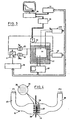
- Figure 1 represents a block diagram of a set-up apparatus according to an embodiment of the present invention.
- Figure 2 represents a block diagram similar to that of figure 1, showing an apparatus for the calibration step of the temperature sensitive electrical parameters according to the present invention.
- Figure 3 represents a block diagram of a measurement set-up apparatus according to a further embodiment of the present invention for the thermal response measurement step.
- Figure 4 is a graph representing a liquid jet impingement construction used to create one or more parallel impinging liquid jets on the main surfaces of the packaged semiconductor chip according to a variant of the present invention.
- Figures 5 and 8 represent typical calibration curves obtained by the measurement system related to the present invention.
- Figures 6 and 7 show curves representing average convective heat transfer coefficient as function of the number of outlet nozzles and nozzle diameter with as working fluids water, resp. FC-70.
- the apparatus for the measurement set-up as schematically shown in figure 1, wherein 9 represents a thermal impedance evaluation system comprises a processing unit, e.g. a computer 10, that may be equipped with instrument control software, and connected to the measurement and control instruments by means of a GPIB interface 11.
- a thermostatic fluid bath 12 is included in the apparatus.
- the bath vessel is filled with a dielectric fluid 13, such as silicone oil or a fluorinert liquid.
- a fluid with a boiling point above 100°C and a pour point below -25°C is selected.
- An I/O interface 18 is used for controlling the setpoint of the thermostatic bath.
- Said bath 12 serves as a controlled temperature environment capable of maintaining the whole semiconductor chip and package 14 within +/- 0.1°C of the liquid temperature during calibration step of the temperature sensitive electrical parameters.
- the semiconductor chip 14 is immersed in said liquid 13, and is surrounded by a liquid jet impingement construction 15, comprising a tubing system 35, 36 and one or more nozzles 37 which are directed towards one or more package surfaces.
- a circulator pump 16 provides the required flow rate indicated by the direction of arrow referenced with F to obtain one or more high velocity impinging liquid jets 38 on the package surfaces of the semiconductor chip 14.
- the liquid temperature is measured using a temperature sensor 17, which may be a platinum thermometer.
- a multimeter 22 is destined to read the value of the temperature sensitive electrical parameter during the calibration step, and the value of the heating voltage and heating current during the power pulse application of the thermal response measurement step.
- the second multimeter 21 reads the output of the temperature sensor 17 during the calibration and thermal response step.
- a constant current source 23 is also included in the apparatus. This current source provides a fixed small current during the calibration and thermal response measurement, as shown in figure 2 and 3. The current is set in the range 100 ⁇ A to 100 mA.
- a power supply 24 provides the heating power in the semiconductor chip under test during the thermal response measurement step.
- an electronic switch 5 is used to apply and remove the heating power during the thermal response measurement step, or during an ageing test.
- This electronic switch is controlled by a wave form generator 26 or an I/O interface.
- a digital storage oscilloscope 25 or digital storage multimeter is included in the apparatus.
- the described instruments 21 ... 26 are controlled by the computer over a GPIB-interface 11.
- the measured data is read and stored for post-processing purposes.
- the method of thermal impedance measurement according to the present invention consists of two major steps: a calibration step and a thermal response measurement step.
- the calibration step is performed by immersing the packaged semiconductor chip under test in the thermostatic bath 12 that acts as temperature controlled environment. During this calibration step, the temperature of the semiconductor chip is externally governed by the liquid, the value of the temperature sensitive electrical parameter is measured and recorded at different pre-set temperature setpoints.
- the apparatus required for the calibration of the voltage drop of a forward polarised diode 14 is shown in figure 2.
- the device is heated for a certain time period by applying an electrical power pulse at the junction region of the semiconductor chip.
- the dissipated power is measured.
- its heating and/or cooling response is monitored as function of time on the digital storage oscilloscope 25 or multimeter. Then, the stored response of the temperature sensitive electrical parameter is converted into a temperature response according to the relationship derived in the calibration step.
- the calibration is done by immersing the chip into a thermostatic bath, filled with a dielectric liquid.
- an appropriate temperature sensitive electrical parameter inside the chip must be calibrated versus temperature.
- the temperature sensitive electrical parameter and the magnitude of the calibration current shall be chosen so that the value of the parameter is a linear function over the normal operating temperature range of the chip.
- the electrical parameter should yield the maximum temperature inside the chip.
- Useful temperature sensitive electrical parameters are the forward diode voltage for power diodes, base-emitter voltage for bipolar transistors, source-drain diode voltage or gate-source threshold voltage for MOSFETs.
- the temperature of the bath is varied over a certain range, e.g. 10 - 100°C.
- a thermostatic bath is the most accurate kind of controllable temperature environment.
- the temperature of the dielectric liquid is measured, e.g. by a platinum resistance thermometer and the value of the temperature sensitive electrical parameter is recorded.
- the data is automatically regressed and the correlation coefficients are stored in a file directly accessible to the control software during subsequent response measurement.
- the heat dissipation in the chip has to be minimised to be sure that the internal temperature is equal to the liquid temperature. This can be accomplished by choosing the measurement current in the range 100 ⁇ A for small devices to 100 mA for larger ones.
- Figure 5 shows the calibration curve for the forward polarised base-emitter voltage of an npn bipolar transistor as function of temperature. This curve was constructed for a calibration current equal to 100 ⁇ A and represents a linear relationship between temperature sensitive electrical parameter TSEP and temperature T. The collector-base voltage was set to 15V.
- Figure 8 shows an analogue calibration curve for the gate-source voltage versus temperature for an N-channel TMOS power FET transistor.
- the calibration drain-source current is 100 ⁇ A.
- the drain-gate voltage was set to 15V.
- Figure 3 represents the measurement set-up for the thermal response measurement step.
- the chip under test 14 is immersed in the thermostatic fluid bath 12 while the liquid temperature is maintained at a pre-set value.
- the liquid is recirculated in the bath by means of a pump.
- the packaged semiconductor chip is cooled by one or more submerged impinging liquid jets, using a construction as shown in figure 4.
- One or more impinging liquid jets 38 are directed substantially perpendicular to the surfaces of the packaged semiconductor chip 14 under test.
- One or more nozzles 37 in the outlet plane 39 increase the outlet velocity to obtain the liquid jets 38.
- the convective heat transfer between fluid and package is characterised by such high heat transfer coefficients, that the package surface is quasi-isothermal and its temperature approximates the liquid temperature.
- the number and diameter of said nozzles 37, and capacity of said pump is chosen to ensure that the external temperature drop between package and fluid never exceeds a pre-determined value.
- the reference package temperature is then obtained by measuring the controlled liquid temperature. Measurement of the liquid temperature can be performed by an accurate platinum resistance thermometer, without disturbing the heat transfer between package and liquid. For obtaining large heat transfer coefficients at a surface is involved the use of one or more impinging jets.
- Convective heat transfer coefficients of the order of 10.000W/m 2 may be achieved using liquid impinging jets. These high convective heat transfer coefficients are wellsuited to improve the thermal characterisation of electronic packages in a fluid bath environment.
- a big advantage of impingement cooling is the small external temperature difference between case and fluid.
- a simple calculation, assuming a heat transfer coefficient of 40.000 W/m 2 K shows that the external convective thermal resistance for a 2cm by 2cm surface area is as low as 0,0625 K/W, which is much smaller than the experimental measurement accuracy obtained by the actual R jc standard methods.
- the optimal nozzle outlet configuration i.e. number of parallel nozzles, nozzle diameter ⁇ , and nozzle-to-package separation distance, a fundamental understanding of the hydrodynamic and thermal conditions of an impinging jet flow is required.
- Liquid jet inpingement cooling schemes can be divided into two categories: free surface jet impingement and submerged jet impingement.
- a free surface jet is discharged into an ambient gas, while a submerged jet is discharged into a stagnant fluid of the same type.
- These two types of impinging jets significantly differ in their hydrodynamic and thermal performance.
- a free surface jet flow is characterised by a very small shear stress at the liquid/gas interface. In the absence of gravitational acceleration, the jet diameter and the nozzle exit velocity are preserved until impingement on the target surface. This hydrodynamic behaviour causes the convective heat transfer between fluid and surface to be independent of the nozzle-to-surface separation distance.
- a submerged liquid jet is characterised by a shear layer between jet and the surrounding fluid.
- the local and average convective heat transfer coefficients are affected by nozzle exit velocity profile, jet turbulence, jet Reynolds number, nozzle-to-surface distance, and the size of the target surface.
- Several correlations for the average Nusselt number are available in literature. Womac et al. proposed an area-weighted combination of correlations for the two surface regions; the impingement region was assumed to extend to a radius of 1,9 and to be followed by transition to a turbulent wall jet region.
- the same correlation can be used to calculate the average convective heat transfer coefficient.
- the lenght L in equations (4) (5) and (6) has to be replaced by the pitch P between the nozzles.
- the use of multiple jets has the potential to maintain a greater degree of temperature uniformity across the surface. Though jet interactions may influence the local heat transfer conditions.
- the Womac correlation (4) for single and multiple unconfined circular jets was then used to calculate the optimal number of parallel jets and the optimal nozzle outlet diameter.
- the actual flow rate was determined as the intersect of the circulation pump characteristic (thermostatic bath) and the load curve of the tubes and nozzle contractions.
- the outlet flow rate of the circulation pump is split into two parallel flows which are impinged substantially perpendicularly to the top and bottom surfaces of the package.
- a schematic view of the proposed mounting arrangement is given in figure 4.
- the optimal nozzle diameter ⁇ of both water and FC-70 can be obtained from the graphs in figure 6 respectively 7, showing each in the upper right corner the amount of nozzles for each corresponding symbol.
- the thermal response measurement step starts with the adjustment of the heating current I H and the measurement current I M , which must be equal to the calibration current.
- the value of I H is usually at least two orders of magnitude greater than the value of I M .
- An electronic switch 5 allows one to rapidly apply and remove the heating current from the test chip, while the small measurement current I H is always flowing.
- the switch 5 can take two positions: an open position A and a closed position B.
- the position of switch 5 is controlled by a wave form generator 26 or I/O interface.
- the switch is in open position A, the value of the temperature sensitive electrical parameter is measured which provides the initial device temperature. Then the device is heated for a short period of time, by switching the switch 5 to the closed position B.
- the dissipated power is measured as the product of the heating current I H and the heating voltage V H resulting from application of this current.
- the switch 5 is again moved to the open position A and the heating and/or cooling response of the temperature sensitive electrical parameter is stored in memory of the digital storage oscilloscope 25 or multimeter. Next, the response of the temperature sensitive electrical parameter is converted into a temperature response using the calibration curve.
- the invention thus represents a non-destructive and reproducible test method to evaluate the steady-state and transient thermal performance of electronic chips.
- the measurement procedure related to the present invention allows a qualitative evaluation of the mechanical integrity of the semiconductor chip and chip attach based on the thermal characteristics.
- the described apparatus offers the possibility to trace ageing of electronic chips due to power and temperature cycling.
- a power pulse is applied to the semiconductor chip while it is immersed in a thermostatic fluid bath.
- the temperature of the bath is kept at very low temperature, e.g. -25°C, using the submerged impingement construction.
- the power dissipation has to be adjusted as high as the junction temperature reaches its maximum specified operating temperature. This induces a thermal load cycle, creating a large thermal mismatch between the different layers of the packaged semiconductor chip.
- the junction region of the chip is allowed to reach thermal equilibrium with the fluid.
- the power and temperature cycle can now be repeated. Those power cycles can be alternated with thermal impedance measurements, consisting of calibration step and thermal response measurement step as described previously.
- Alternating the power cycles at regular time intervals with a thermal impedance measurement provides the in-situ change of thermal impedance, and allows investigation of the ageing kinetics under thermal load condition.
- a remarkable advantage of the present invention is the minimal requirement of knowledge and experience about the measurement set-up due to the fact that all measurements are completely controlled by the operating software. Initialisation and configuration of the instrumentation system is done automatically.
- thermostatic bath with submerged liquid jet impingement scheme creates a very stable, uniform, reproducible and accurate temperature chamber. This allows a very accurate calibration of the temperature sensitive electrical parameters and accurate knowledge of the package reference temperature during thermal response measurement.
Landscapes
- Physics & Mathematics (AREA)
- Health & Medical Sciences (AREA)
- Life Sciences & Earth Sciences (AREA)
- Chemical & Material Sciences (AREA)
- Analytical Chemistry (AREA)
- Biochemistry (AREA)
- General Health & Medical Sciences (AREA)
- General Physics & Mathematics (AREA)
- Immunology (AREA)
- Pathology (AREA)
- Testing Of Individual Semiconductor Devices (AREA)
- Investigating Or Analyzing Materials Using Thermal Means (AREA)
- Testing Or Measuring Of Semiconductors Or The Like (AREA)
Abstract
Description
- The present invention relates to an apparatus and method for measuring the thermal impedance of packaged semiconductor chips.
- The operating temperature is one of the most important factors affecting the reliability and performance of semiconductor chips. Large scale integration of integrated circuits leads to a higher power density, and means more and more heat dissipation per surface area of the semiconductor chip. Materials, packages, processing and cooling methods of semiconductor chips have to meet strong requirements to keep the operating temperature below a critical junction temperature specified by the manufacturer and which must not be exceeded or failure of the semiconductor chip will occur. Especially high technology and power devices must effectively transfer heat to the ambient.
- Thermal performance of packaged semiconductor chips is traditionally expressed by the steady-state junction-to-case thermal resistance between junction and some reference location at the package. The thermal resistance is defined as Rth=(Tj-Tref)/P, wherein Tj denotes the highest chip temperature further referred to as the junction temperature, Tref is some reference temperature at the package, and P denotes the electrical power being dissipated in the semiconductor chip. Standard measurement procedures such as SEMI G30-88, SEMI G43-87, MIL-STD-883C, Method 1012 should maintain consistent and repetitive results. These methods offer a choice of using either a fluid bath or a heat-sink environment and both assume that the measured thermal resistance is independent of such environmental choice. Unfortunately, the environmental conditions (e.g. flow field in fluid bath, circulation rate) may strongly influence the measured junction-to-case thermal resistance. As a result, strong differences in thermal resistance can be measured when using the same standard method in different environmental conditions. Moreover, according to the mentioned standards, the reference temperature is measured using a thermocouple in contact with the package surface. Attachment of a thermocouple heavily disturbs the heat transfer between package and environment. Large system disturbance errors are thus introduced in the measurement chain, resulting in huge uncertainties of the actual thermal resistance value.
- As the reliability of semiconductor chips does not only depend on the steady-state temperature, but also on temperature changes and gradients, measurement of the transient thermal behaviour of semiconductor chips has gained increasing importance. The thermal impedance, defined as the transient thermal resistance, contains a lot of information concerning the semiconductor chip integrity and chip attach quality. Thermal impedance measurement techniques are described in MIL-STD-750C for various devices, such as diodes and transistors. The environmental conditions are not specified, though it is assumed that the package reference location is kept at a constant temperature.
- There are disclosed in "Journal de la Physique, Part 3, Number 3, April 1993, Paris, of Pierre Paris, Jean-Marie Hausonne et Jean Lostec, for "Appareil permettant la caractérisation thermique de substrats et matériaux à forte conductibilité pour micro-électronique" an apparatus and method for characterising the thermal conductivity of substrates used in semiconductor packaging. This method is limited to measure the thermal properties of ceramic substrate samples and cannot be applied to packaged semiconductor chips.
- US patent No. 4.840.495 describes a method and apparatus for measuring the thermal resistance of a chip assembly including a semiconductor chip which is glued on a substrate. This method requires the semiconductor chip being accessible at the heat source side. Though, in a lot of applications a semiconductor chip is enclosed in some type of package which prevents a direct contact at the chip heat source. Thus it is not possible, with the methods of the prior art, to measure the thermal resistance of fully packaged semiconductor chips.
- Due to the inaccessibility of the packaged semiconductor chip, an indirect but non destructive method is used to determine the junction temperature, which is defined as highest temperature. Temperature sensitive electrical parameters on the chip can be used as thermometers for indirect sensing of chip temperature.
- It is an object of the present invention to provide a solution for the aforementioned problems and to provide an apparatus and a method for accurate and reproducible measurement of the thermal impedance of packaged semiconductor chips, particularly with a high circuit density.
- Accordingly, there is provided according to the present invention an apparatus for evaluating the thermal impedance of a packaged semiconductor chip according to claim 1.
- It is further object of the present invention to provide a method and apparatus for in-situ monitoring the presence and growth of defects in the semiconductor chip and package under power cycling.
- According to a further embodiment of the invention, said at least one measuring unit is formed by a temperature sensor for measuring the temperature of the fluid in said bath; and said apparatus further comprises means for adjusting the temperature of said bath; means for measuring the value of a temperature sensitive electrical parameter of the semiconductor chip being evaluated; means for forcing a small current to allow measurement of said temperature sensitive electrical parameter; means for dissipating electrical power in said semiconductor chip; switching means for switching said power rapidly on and off; means for measuring the value of said electrical power; and means for monitoring and storing the value of said temperature sensitive electrical parameter as function of time.
- According to a preferred embodiment of the invention, said thermostatic bath is filled with a dielectric, fluid and more particularly, said dielectric fluid is a silicone oil or Fluorinert liquid with boiling point above 100°C and pour point less than -25°C.
- More specifically, the present invention aims at solving the problems related to the mentioned standard methods for measuring the steady-state and transient thermal performance of semiconductor chips. According to a further preferred embodiment of the present invention, the apparatus therefor further comprises a pump means for recirculating said fluid in said bath. Therewith, a uniform, reproducible, stable, and accurate thermal boundary condition can be created and achieved for the packaged chip as well during calibration of the temperature sensitive electrical parameter as during the actual thermal response measurement.
- According to a variant of the present invention, said apparatus further comprises means to create one or more impinging liquid jets that are directed with a predetermined angle, preferably substantially perpendicularly, relative to the surfaces of the packaged semiconductor chip being evaluated. Therefore, an appropriate submerged liquid jet impingement cooling scheme has been constructed.
- In connection with said circulator pump, the required fluid outlet velocity can be achieved, and said one or more liquid jets impinging at one or more package surfaces can be created with a perfect reliability.
- According to a preferred embodiment of the latter, said liquid jet creating means comprise at least one nozzle.
- According to a further preferred embodiment thereof, the number and diameter of said nozzles, and capacity of said pump is chosen to ensure that the external temperature drop between package and fluid never exceeds a pre-determined value. The convective heat transfer between fluid and package is characterised by such high heat transfer coefficients, that the package surface is quasi-isothermal and its temperature always approximates the liquid temperature. Measurement of the liquid temperature can be performed by an accurate platinum resistance thermometer, without disturbing the heat transfer between package and liquid.
- A measuring apparatus for performing the method according to a preferred combination in the present invention is remarkable in that it includes said thermostatic bath unit with said circulator pump and liquid jet impingement construction, and filled with a dielectric liquid, the liquid temperature being measured with a temperature sensor, a current source to supply the small calibration current during calibration and thermal response measurement, a power supply to dissipate the power during thermal response measurement, a digital storage oscilloscope or multimeter to capture and store the response of the temperature sensitive electrical parameter, and a wave form generator or I/O interface to rapidly apply and remove the power pulse to the chip under test.
- There is also provided a method for measuring the thermal impedance of packaged semiconductor chips by means of an apparatus according to claim 1, comprising the steps of claim 10.
- More specifically, the method of the present invention includes a calibrating step which is carried out by controlling the temperature of said liquid over a range of pre-set temperature values and recording the value of the temperature sensitive electrical parameter and the value of the liquid temperature when thermal equilibrium is reached at each temperature setpoint, and wherein an electrical power pulse is dissipated in the semiconductor chip during said thermal response measurement step.
- Still further, said electrical power is measured; the value of a temperature sensitive electrical parameter is monitored and stored as function of time during and/or after the application said power pulse; and wherein the response of said temperature sensitive electrical parameter is converted into a temperature response using the data obtained in the calibrating step.
- It can further specifically be provided that said temperature sensitive electrical parameter yields the highest temperature of the semiconductor chip.
- According to an advantageous embodiment of the method in the present invention, said temperature sensitive electrical parameter is chosen in such a way to obtain a linear relationship between said temperature sensitive electrical parameter and temperature.
- Another drawback of the traditional methods described in the mentioned standards is their limitation to momentary evaluation of the thermal resistance, i.e. the evolution in time due to power or temperature cycles cannot be monitored using the same equipment. The traditional methods require the test chip to be transferred to another apparatus in order to subject it to temperature cycles.
- According to a preferred embodiment of the method of the invention, it further comprises the step of monitoring in-situ thermal degradation of the packaged semiconductor chip by alternating the calibration and thermal response measurement step with a power cycling step. The measurement method can thus be applied more particularly for measuring in-situ thermal degradation in the semiconductor chip and package due to power cycling. Power cycles induce temperature cycles which may affect on-chip electrical parameters and cause defects such as cracks, voids, delamination in the semiconductor chip and package.
- The method of the present invention thus allows power cycling and thermal impedance evaluation using the same apparatus. Changes in thermal impedance can be monitored in-situ during a long period of thermal loading. A temperature cycle is induced by heating the semiconductor junction region for a short period, followed by thermal equilibrium at the liquid temperature. After a certain number of such cycles, a thermal impedance measurement is performed. The present invention can thus be used to monitor the thermal degradation of semiconductor chips.
- More specifically, said power cycling step includes the application of a pulsed power signal. The transient thermal impedance is an extremely important characteristic of a semiconductor chip. It contains a lot of information about the thermal properties of the semiconductor chip and chip attach region. Due to the difference in thermal time constants of the semiconductor chip and the package, the thermal impedance is much more sensitive to the presence of voids and cracks than the steady-state thermal resistance. The chip thermal time constant is generally some orders of magnitude smaller than that of the package. By heating the device with a power pulse, short enough such that the heat energy only has the time to flow through the chip and into the chip attach area, the temperature rise includes only the chip and chip attach resistance. In addition, for devices working under pulsed power operation conditions, it is the transient thermal impedance which determines by how much and for how long the DC power dissipation level of the device can safely be exceeded.
- According to a further preferred embodiment, the amplitude, period and duty cycle of said power signal form is chosen in such a way to get the maximum junction temperature near a critical temperature, and to allow thermal equilibrium between to successive power pulses.
- In the present invention, the thermal performance is determined by two important characteristics, the steady-state thermal resistance between junction and (quasi)-isothermal case, and the thermal impedance when a heating pulse is applied to the junction region of the semiconductor chip. In the present method according to the invention, the steady-state thermal resistance between junction and case is obtained by increasing the heating pulse duration length until the junction temperature reaches equilibrium.
- In order to create a large temperature difference between package and junction which exceeds a pre-determined value, the power cycling step preferably further comprises the step of controlling the fluid temperature at a low value e. g., between -50°C and 0°C.
- In a preferred mutual combination, the method of measurement of thermal impedance according to the invention is remarkable in that it comprises a calibration step to derive the relationship between an on-chip temperature sensitive electrical parameter and temperature, being performed by immersing the packaged semiconductor chip in a thermostatic bath with circulator pump and filled with a dielectric liquid, thereby providing a perfectly stable, uniform and accurate temperature chamber. The method of measurement of thermal impedance according to the invention is further characterised in that it comprises a thermal response measurement step while the semiconductor chip is immersed in the fluid bath and cooled by one or more impinging liquid jets, comprising the application of a power pulse, removal of the power pulse, capturing and storing of the temperature sensitive electrical parameter during heating and/or cooling down, converting the response of this parameter to temperature using the previously derived calibration relationship, and calculating the thermal impedance from the junction thermal response, the measured liquid temperature, and measured heating power.
- According to a further embodiment according to the invention it can be used for monitoring in-situ change of thermal impedance due to thermal degradation, by alternating a certain number of power cycles in the semiconductor chip with a thermal impedance measurement, without the need for supplementary apparatus.
- Further features and advantages of the invention will become clear from the detailed description of an exemplary embodiment, in conjunction with the drawings.
- Figure 1 represents a block diagram of a set-up apparatus according to an embodiment of the present invention.
- Figure 2 represents a block diagram similar to that of figure 1, showing an apparatus for the calibration step of the temperature sensitive electrical parameters according to the present invention.
- Figure 3 represents a block diagram of a measurement set-up apparatus according to a further embodiment of the present invention for the thermal response measurement step.
- Figure 4 is a graph representing a liquid jet impingement construction used to create one or more parallel impinging liquid jets on the main surfaces of the packaged semiconductor chip according to a variant of the present invention.
- Figures 5 and 8 represent typical calibration curves obtained by the measurement system related to the present invention.
- Figures 6 and 7 show curves representing average convective heat transfer coefficient as function of the number of outlet nozzles and nozzle diameter with as working fluids water, resp. FC-70.
- The apparatus for the measurement set-up as schematically shown in figure 1, wherein 9 represents a thermal impedance evaluation system, comprises a processing unit, e.g. a computer 10, that may be equipped with instrument control software, and connected to the measurement and control instruments by means of a GPIB interface 11. A thermostatic fluid bath 12 is included in the apparatus. The bath vessel is filled with a dielectric fluid 13, such as silicone oil or a fluorinert liquid. Preferably, a fluid with a boiling point above 100°C and a pour point below -25°C is selected. An I/O interface 18 is used for controlling the setpoint of the thermostatic bath. Said bath 12 serves as a controlled temperature environment capable of maintaining the whole semiconductor chip and package 14 within +/- 0.1°C of the liquid temperature during calibration step of the temperature sensitive electrical parameters. The semiconductor chip 14 is immersed in said liquid 13, and is surrounded by a liquid jet impingement construction 15, comprising a tubing system 35, 36 and one or more nozzles 37 which are directed towards one or more package surfaces. A circulator pump 16 provides the required flow rate indicated by the direction of arrow referenced with F to obtain one or more high velocity impinging liquid jets 38 on the package surfaces of the semiconductor chip 14. The liquid temperature is measured using a temperature sensor 17, which may be a platinum thermometer.
- A multimeter 22 is destined to read the value of the temperature sensitive electrical parameter during the calibration step, and the value of the heating voltage and heating current during the power pulse application of the thermal response measurement step. The second multimeter 21 reads the output of the temperature sensor 17 during the calibration and thermal response step.
- A constant current source 23 is also included in the apparatus. This current source provides a fixed small current during the calibration and thermal response measurement, as shown in figure 2 and 3. The current is set in the range 100 µA to 100 mA.
- A power supply 24 provides the heating power in the semiconductor chip under test during the thermal response measurement step.
- As shown in figure 3, an electronic switch 5 is used to apply and remove the heating power during the thermal response measurement step, or during an ageing test. This electronic switch is controlled by a wave form generator 26 or an I/O interface.
- In order to record the temperature sensitive electrical parameter as function of time during heating and/or cooling of the semiconductor chip, a digital storage oscilloscope 25 or digital storage multimeter is included in the apparatus.
- The described instruments 21 ... 26 are controlled by the computer over a GPIB-interface 11. The measured data is read and stored for post-processing purposes.
- The method of thermal impedance measurement according to the present invention consists of two major steps: a calibration step and a thermal response measurement step.
- The calibration step is performed by immersing the packaged semiconductor chip under test in the thermostatic bath 12 that acts as temperature controlled environment. During this calibration step, the temperature of the semiconductor chip is externally governed by the liquid, the value of the temperature sensitive electrical parameter is measured and recorded at different pre-set temperature setpoints. The apparatus required for the calibration of the voltage drop of a forward polarised diode 14 is shown in figure 2.
- During the thermal response measurement step, the device is heated for a certain time period by applying an electrical power pulse at the junction region of the semiconductor chip. The dissipated power is measured. Depending on the art of the temperature sensitive electrical parameter, its heating and/or cooling response is monitored as function of time on the digital storage oscilloscope 25 or multimeter. Then, the stored response of the temperature sensitive electrical parameter is converted into a temperature response according to the relationship derived in the calibration step.
- The calibration is done by immersing the chip into a thermostatic bath, filled with a dielectric liquid. In order to characterise the transient thermal behaviour of semiconductor chips in an indirect way, an appropriate temperature sensitive electrical parameter inside the chip must be calibrated versus temperature. The temperature sensitive electrical parameter and the magnitude of the calibration current shall be chosen so that the value of the parameter is a linear function over the normal operating temperature range of the chip. In addition the electrical parameter should yield the maximum temperature inside the chip. Useful temperature sensitive electrical parameters are the forward diode voltage for power diodes, base-emitter voltage for bipolar transistors, source-drain diode voltage or gate-source threshold voltage for MOSFETs.
- The temperature of the bath is varied over a certain range, e.g. 10 - 100°C. A thermostatic bath is the most accurate kind of controllable temperature environment.
- Once the value of the temperature sensitive electrical parameter has stabilised, the temperature of the dielectric liquid is measured, e.g. by a platinum resistance thermometer and the value of the temperature sensitive electrical parameter is recorded. The data is automatically regressed and the correlation coefficients are stored in a file directly accessible to the control software during subsequent response measurement. During the calibration step, the heat dissipation in the chip has to be minimised to be sure that the internal temperature is equal to the liquid temperature. This can be accomplished by choosing the measurement current in the range 100 µA for small devices to 100 mA for larger ones.
- Figure 5 shows the calibration curve for the forward polarised base-emitter voltage of an npn bipolar transistor as function of temperature. This curve was constructed for a calibration current equal to 100 µA and represents a linear relationship between temperature sensitive electrical parameter TSEP and temperature T. The collector-base voltage was set to 15V.
- Figure 8 shows an analogue calibration curve for the gate-source voltage versus temperature for an N-channel TMOS power FET transistor. The calibration drain-source current is 100µA. The drain-gate voltage was set to 15V.
- Figure 3 represents the measurement set-up for the thermal response measurement step. The chip under test 14 is immersed in the thermostatic fluid bath 12 while the liquid temperature is maintained at a pre-set value. The liquid is recirculated in the bath by means of a pump.
- The packaged semiconductor chip is cooled by one or more submerged impinging liquid jets, using a construction as shown in figure 4. One or more impinging liquid jets 38 are directed substantially perpendicular to the surfaces of the packaged semiconductor chip 14 under test. One or more nozzles 37 in the outlet plane 39 increase the outlet velocity to obtain the liquid jets 38. The convective heat transfer between fluid and package is characterised by such high heat transfer coefficients, that the package surface is quasi-isothermal and its temperature approximates the liquid temperature. The number and diameter of said nozzles 37, and capacity of said pump is chosen to ensure that the external temperature drop between package and fluid never exceeds a pre-determined value. The reference package temperature is then obtained by measuring the controlled liquid temperature. Measurement of the liquid temperature can be performed by an accurate platinum resistance thermometer, without disturbing the heat transfer between package and liquid.
For obtaining large heat transfer coefficients at a surface is involved the use of one or more impinging jets. - Convective heat transfer coefficients of the order of 10.000W/m2 may be achieved using liquid impinging jets. These high convective heat transfer coefficients are wellsuited to improve the thermal characterisation of electronic packages in a fluid bath environment. A big advantage of impingement cooling is the small external temperature difference between case and fluid. A simple calculation, assuming a heat transfer coefficient of 40.000 W/m2K shows that the external convective thermal resistance for a 2cm by 2cm surface area is as low as 0,0625 K/W, which is much smaller than the experimental measurement accuracy obtained by the actual Rjc standard methods. In order to find the optimal nozzle outlet configuration, i.e. number of parallel nozzles, nozzle diameter , and nozzle-to-package separation distance, a fundamental understanding of the hydrodynamic and thermal conditions of an impinging jet flow is required.
- Liquid jet inpingement cooling schemes can be divided into two categories: free surface jet impingement and submerged jet impingement. A free surface jet is discharged into an ambient gas, while a submerged jet is discharged into a stagnant fluid of the same type. These two types of impinging jets significantly differ in their hydrodynamic and thermal performance. A free surface jet flow is characterised by a very small shear stress at the liquid/gas interface. In the absence of gravitational acceleration, the jet diameter and the nozzle exit velocity are preserved until impingement on the target surface. This hydrodynamic behaviour causes the convective heat transfer between fluid and surface to be independent of the nozzle-to-surface separation distance. A submerged liquid jet is characterised by a shear layer between jet and the surrounding fluid. Experiments with both water and FC-77 have shown that the convective heat transfer coefficient is higher for a submerged jet with S/d=3 than for a free surface jet, for Red > 4000. The higher Nusselt numbers obtained with the submerged jet can be attributed to heat transfer enhancement by turbulence generated in the free shear layer of the jet. For submerged jets, the Nusselt number (and heat transfer coefficient) is quasi independant of S/d for 1 < S/d < 4. This can be explained by the fact that, for 1 < S/d < 4, the heat source is still located within the potential core of the jet. Furthermore the Nusselt number decreases with increasing S/d ratio for large separation distances. The highest heat transfer coefficients are thus obtained for submerged jets and small S/d values, i.e. S/d ≤ 4.
- For an unconfined, submerged circular jet, the local and average convective heat transfer coefficients are affected by nozzle exit velocity profile, jet turbulence, jet Reynolds number, nozzle-to-surface distance, and the size of the target surface. At this point, the ratio S/d is set at a fixed value S/d= 4...5. The size of the target surface depends on the chip and package size. To be useful for most package types, a heater surface with length L = 25 mm is presumed. Several correlations for the average Nusselt number are available in literature. Womac et al. proposed an area-weighted combination of correlations for the two surface regions; the impingement region was assumed to extend to a radius of 1,9 and to be followed by transition to a turbulent wall jet region.where

- m = 0,5
- n = 0,8
- C1 = 0,785
- C2 = 0,0257 and L* denotes the average lenght of the wall region:
-
- For multiple, unconfined submerged jet configurations, the same correlation can be used to calculate the average convective heat transfer coefficient. In this case, the lenght L in equations (4) (5) and (6) has to be replaced by the pitch P between the nozzles. The use of multiple jets has the potential to maintain a greater degree of temperature uniformity across the surface. Though jet interactions may influence the local heat transfer conditions.
- The Womac correlation (4) for single and multiple unconfined circular jets was then used to calculate the optimal number of parallel jets and the optimal nozzle outlet diameter. The actual flow rate was determined as the intersect of the circulation pump characteristic (thermostatic bath) and the load curve of the tubes and nozzle contractions. The outlet flow rate of the circulation pump is split into two parallel flows which are impinged substantially perpendicularly to the top and bottom surfaces of the package. A schematic view of the proposed mounting arrangement is given in figure 4. The optimal nozzle diameter of both water and FC-70 can be obtained from the graphs in figure 6 respectively 7, showing each in the upper right corner the amount of nozzles for each corresponding symbol.
- It appears that water has much better thermal properties than fluorinert liquids. When using water as the cooling fluid, heat transfer coefficients in the order of 40.000 W/m2K can be obtained for an array of 5 x 5 nozzles with diameter = 0,5 mm. Also for fluorinert FC-70, an array of multiple small nozzles yields the highest heat transfer coefficients. The optimal nozzle outlet diameter is somewhat larger than for water; and the accompanying average heat transfer coefficient is about ten times smaller. Though, comparing to an initial value of about 100 to 200 W/m2K, the heat transfer coefficient has increased significantly and more important, the flow field is well-defined, resulting in reproducible values for Rja which will approximate Rjc. The graphs below were calculated for a circulation pump with a maximum flow rate of 15 litre/min and maximum pressure drop of 480 mbar.
- The thermal response measurement step starts with the adjustment of the heating current IH and the measurement current IM, which must be equal to the calibration current. The value of IH is usually at least two orders of magnitude greater than the value of IM.
- An electronic switch 5 allows one to rapidly apply and remove the heating current from the test chip, while the small measurement current IH is always flowing. The switch 5 can take two positions: an open position A and a closed position B. The position of switch 5 is controlled by a wave form generator 26 or I/O interface. When the switch is in open position A, the value of the temperature sensitive electrical parameter is measured which provides the initial device temperature. Then the device is heated for a short period of time, by switching the switch 5 to the closed position B. The dissipated power is measured as the product of the heating current IH and the heating voltage VH resulting from application of this current. After an adjustable pulse duration, the switch 5 is again moved to the open position A and the heating and/or cooling response of the temperature sensitive electrical parameter is stored in memory of the digital storage oscilloscope 25 or multimeter. Next, the response of the temperature sensitive electrical parameter is converted into a temperature response using the calibration curve.
- The invention thus represents a non-destructive and reproducible test method to evaluate the steady-state and transient thermal performance of electronic chips. The measurement procedure related to the present invention allows a qualitative evaluation of the mechanical integrity of the semiconductor chip and chip attach based on the thermal characteristics.
- In addition, the described apparatus offers the possibility to trace ageing of electronic chips due to power and temperature cycling. To realise a cyclic thermal load, a power pulse is applied to the semiconductor chip while it is immersed in a thermostatic fluid bath. In order to create a large temperature difference between package surface and the semiconductor junction during power dissipation, the temperature of the bath is kept at very low temperature, e.g. -25°C, using the submerged impingement construction. The power dissipation has to be adjusted as high as the junction temperature reaches its maximum specified operating temperature. This induces a thermal load cycle, creating a large thermal mismatch between the different layers of the packaged semiconductor chip. After this power pulse, the junction region of the chip is allowed to reach thermal equilibrium with the fluid. The power and temperature cycle can now be repeated. Those power cycles can be alternated with thermal impedance measurements, consisting of calibration step and thermal response measurement step as described previously.
- Alternating the power cycles at regular time intervals with a thermal impedance measurement provides the in-situ change of thermal impedance, and allows investigation of the ageing kinetics under thermal load condition.
- A remarkable advantage of the present invention is the minimal requirement of knowledge and experience about the measurement set-up due to the fact that all measurements are completely controlled by the operating software. Initialisation and configuration of the instrumentation system is done automatically.
- Furthermore, the thermostatic bath with submerged liquid jet impingement scheme creates a very stable, uniform, reproducible and accurate temperature chamber. This allows a very accurate calibration of the temperature sensitive electrical parameters and accurate knowledge of the package reference temperature during thermal response measurement.
Claims (16)
- An apparatus comprising :characterised in thata) a thermostatic fluid bath (12); andb) at least one measuring unit (17) for measuring the temperature of the fluid (13) of said bath;
said thermostatic fluid bath (12) is provided obtaining a uniform, stable and accurate thermal boundary condition;
said apparatus is provided for evaluating the thermal impedance of a packaged semiconductor chip; and
said apparatus further comprises:c) means (5,23,24,26) for dissipating power in the semiconductor chip;d) means (22) for determining the value of the dissipated power; ande) means (22) for determining the value of a temperature sensitive electrical parameter of the semiconductor chip. - The apparatus as claimed in claim 1, further comprising a liquid jet impinging assembly in said thermostatic fluid bath, said impinging assembly being provided to create at least one impinging liquid jet (38) that are directed with a predetermined angle, preferably substantially perpendicularly, relative to the surfaces of the packaged semiconductor chip (14) being evaluated.
- The apparatus as claimed in claim 2, wherein said liquid jet impinging assembly comprises at least one nozzle (37).
- The apparatus as claimed in any one of the preceding claims, further comprising a pump means (16) for recirculating said fluid (13) in said bath.
- The apparatus as claimed in claim 4 in combination with claim 3, wherein the number and diameter of said nozzles (37), and capacity of said pump (16) is chosen to ensure that the external temperature drop between package and fluid (13) never exceeds a pre-determined value.
- The apparatus as claimed in any one of the preceding claims, wherein said means (5,23,24,26) for dissipating power in the semiconductor chip comprises means for providing a cyclic thermal load on the chip.
- The apparatus as claimed in any one of the preceding claims, wherein said at least one measuring unit is formed by a temperature sensor for measuring the temperature of the fluid in said bath; and said apparatus further comprises means for adjusting the temperature of said bath; means for forcing a small current to allow measurement of said temperature sensitive electrical parameter; switching means for switching said power rapidly on and off; and means for monitoring and storing the value of said temperature sensitive electrical parameter as function of time.
- The apparatus as claimed in any one of the preceding claims, wherein said thermostatic bath (12) is filled with a dielectric fluid.
- The apparatus as claimed in claim 8, wherein said dielectric fluid is a silicone oil or Fluorinert liquid with boiling point above 100°C and pour point less than -25°C.
- A method for measuring the thermal impedance of packaged semiconductor chips by means of an apparatus as claimed in one of the preceding claims comprising the steps of:whereina) immersing the packaged semiconductor chip (14) in a bath (12) filled with a dielectric liquid (13);b) calibrating an on-chip temperature sensitive electrical parameter; andc) measuring a thermal response;
said calibrating step is carried out by controlling the temperature of said liquid (13) over a range of pre-set temperature values and recording the value of the temperature sensitive electrical parameter and the value of the liquid temperature when thermal equilibrium is reached at each temperature setpoint, and
said thermal response measurement step is carried out by dissipating electrical power in the semiconductor chip; determining the value of the dissipated electrical power; determining the value of the temperature sensitive electrical parameter; and converting the response of said temperature sensitive electrical parameter is into a temperature response using the data obtained in the calibrating step. - The method as claimed in the preceding claim, wherein said temperature sensitive electrical parameter yields the highest temperature of the semiconductor chip.
- The method as claimed in the preceding claim, wherein said temperature sensitive electrical parameter is chosen in such a way to obtain a linear relationship between said temperature sensitive electrical parameter and temperature.
- The method as claimed in the preceding claim further comprising the step of monitoring in-situ thermal degradation of the packaged semiconductor chip by alternating the calibration and thermal response measurement step with a power cycling step.
- The method as claimed in the preceding claim, wherein said power cycling step includes the application of a pulsed power signal.
- The method as claimed in the preceding claim, wherein the amplitude, period and duty cycle of said power signal form are chosen in such a way to get the maximum junction temperature near a critical temperature, and to allow thermal equilibrium between two successive power pulses.
- The method as claimed in one of the claims 13 to 15, wherein the power cycling step is further characterised by controlling the fluid temperature at a low value e. g., between -50°C and 0°C, in order to create a large temperature difference between package and junction, which exceeds a pre-determined value.
Applications Claiming Priority (4)
| Application Number | Priority Date | Filing Date | Title |
|---|---|---|---|
| BE9400949A BE1008808A3 (en) | 1994-10-19 | 1994-10-19 | DEVICE AND METHOD FOR EVALUATING THE THERMAL RESISTANCE OF A SEMICONDUCTOR COMPONENT. |
| BE9400949 | 1994-10-19 | ||
| WOPCT/BE95/00085 | 1995-09-18 | ||
| BE9500085 | 1995-09-18 |
Publications (2)
| Publication Number | Publication Date |
|---|---|
| EP0708327A1 EP0708327A1 (en) | 1996-04-24 |
| EP0708327B1 true EP0708327B1 (en) | 2003-07-23 |
Family
ID=3888426
Family Applications (1)
| Application Number | Title | Priority Date | Filing Date |
|---|---|---|---|
| EP95870116A Expired - Lifetime EP0708327B1 (en) | 1994-10-19 | 1995-10-19 | Method and apparatus for thermal impedance evaluation of packaged semiconductor components |
Country Status (6)
| Country | Link |
|---|---|
| US (2) | US5795063A (en) |
| EP (1) | EP0708327B1 (en) |
| JP (1) | JP3872120B2 (en) |
| AT (1) | ATE245811T1 (en) |
| BE (1) | BE1008808A3 (en) |
| DE (1) | DE69531329T2 (en) |
Cited By (2)
| Publication number | Priority date | Publication date | Assignee | Title |
|---|---|---|---|---|
| RU2744716C1 (en) * | 2020-01-27 | 2021-03-15 | федеральное государственное бюджетное образовательное учреждение высшего образования "Ульяновский государственный технический университет" | Method of determining thermal resistance of digital integral microcircuits |
| EP4303549A1 (en) | 2022-07-07 | 2024-01-10 | Mitsubishi Electric R&D Centre Europe B.V. | Process for monitoring thermal resistances in a power electronic system |
Families Citing this family (40)
| Publication number | Priority date | Publication date | Assignee | Title |
|---|---|---|---|---|
| JPH10160597A (en) * | 1996-11-28 | 1998-06-19 | Fenwall Controls Of Japan Ltd | Temperature detection device and its calibration device |
| US7978805B1 (en) * | 1999-07-26 | 2011-07-12 | Massachusetts Institute Of Technology | Liquid gallium cooled high power neutron source target |
| US6984064B1 (en) * | 2002-07-31 | 2006-01-10 | Advanced Micro Devices, Inc. | Thermal transfer measurement of an integrated circuit |
| TWM242691U (en) * | 2003-09-19 | 2004-09-01 | Tatung Co | Automatic test system apparatus |
| JP2005181222A (en) * | 2003-12-22 | 2005-07-07 | Renesas Technology Corp | Manufacturing method of semiconductor device |
| US7191413B2 (en) * | 2004-01-28 | 2007-03-13 | Gradient Design Automation, Inc. | Method and apparatus for thermal testing of semiconductor chip designs |
| US20090048801A1 (en) * | 2004-01-28 | 2009-02-19 | Rajit Chandra | Method and apparatus for generating thermal test vectors |
| US20090224356A1 (en) * | 2004-01-28 | 2009-09-10 | Rajit Chandra | Method and apparatus for thermally aware design improvement |
| US7472363B1 (en) | 2004-01-28 | 2008-12-30 | Gradient Design Automation Inc. | Semiconductor chip design having thermal awareness across multiple sub-system domains |
| US20090077508A1 (en) * | 2004-01-28 | 2009-03-19 | Rubin Daniel I | Accelerated life testing of semiconductor chips |
| US7248988B2 (en) * | 2004-03-01 | 2007-07-24 | Transmeta Corporation | System and method for reducing temperature variation during burn in |
| US8286111B2 (en) * | 2004-03-11 | 2012-10-09 | Gradient Design Automation Inc. | Thermal simulation using adaptive 3D and hierarchical grid mechanisms |
| US8019580B1 (en) | 2007-04-12 | 2011-09-13 | Gradient Design Automation Inc. | Transient thermal analysis |
| EP1960921A1 (en) * | 2005-12-17 | 2008-08-27 | Gradient Design Automation, Inc. | Simulation of ic temperature distributions using an adaptive 3d grid |
| US7507019B2 (en) | 2006-05-19 | 2009-03-24 | Covidien Ag | Thermometer calibration |
| US20070268952A1 (en) * | 2006-05-19 | 2007-11-22 | Sherwood Services Ag | Thermometer calibration by immersion in non-electrically conductive liquid |
| US7549792B2 (en) | 2006-10-06 | 2009-06-23 | Covidien Ag | Electronic thermometer with selectable modes |
| CN101435852B (en) * | 2008-12-12 | 2010-08-25 | 北京工业大学 | A method for measuring light efficiency degradation parameters of junction semiconductor light-emitting devices by electrical method |
| US8490679B2 (en) | 2009-06-25 | 2013-07-23 | International Business Machines Corporation | Condenser fin structures facilitating vapor condensation cooling of coolant |
| US8014150B2 (en) | 2009-06-25 | 2011-09-06 | International Business Machines Corporation | Cooled electronic module with pump-enhanced, dielectric fluid immersion-cooling |
| US8059405B2 (en) | 2009-06-25 | 2011-11-15 | International Business Machines Corporation | Condenser block structures with cavities facilitating vapor condensation cooling of coolant |
| US7885074B2 (en) | 2009-06-25 | 2011-02-08 | International Business Machines Corporation | Direct jet impingement-assisted thermosyphon cooling apparatus and method |
| US8018720B2 (en) | 2009-06-25 | 2011-09-13 | International Business Machines Corporation | Condenser structures with fin cavities facilitating vapor condensation cooling of coolant |
| CN102221566B (en) * | 2011-03-31 | 2013-04-10 | 北京大学 | Method for testing thermal boundary resistance between different materials by utilizing DC source |
| RU2463618C1 (en) * | 2011-04-08 | 2012-10-10 | Федеральное государственное бюджетное образовательное учреждение высшего профессионального образования "Ульяновский государственный технический университет" | Method for determining thermal impedance of cmos digital integrated microcircuits |
| EP2568268A1 (en) * | 2011-09-07 | 2013-03-13 | kk-electronic a/s | Method for estimating the temperature of a semiconductor chip |
| US9323870B2 (en) | 2012-05-01 | 2016-04-26 | Advanced Micro Devices, Inc. | Method and apparatus for improved integrated circuit temperature evaluation and IC design |
| US10156512B2 (en) * | 2013-03-01 | 2018-12-18 | Futurewei Technologies, Inc. | System and method for measuring thermal reliability of multi-chip modules |
| US9442025B2 (en) * | 2013-10-30 | 2016-09-13 | Apple Inc. | System and method for calibrating temperatures sensor for integrated circuits |
| CN103792476B (en) * | 2014-01-17 | 2016-08-17 | 中国空间技术研究院 | Thermo-resistance measurement method for semiconductor device |
| RU2581628C2 (en) * | 2014-02-03 | 2016-04-20 | Федеральное государственное бюджетное образовательное учреждение высшего профессионального образования "Воронежский государственный технический университет" | Quartz reactor to study temperature relationship of electric resistance of high resistor objects |
| RU2630191C1 (en) * | 2016-03-09 | 2017-09-05 | Федеральное государственное бюджетное образовательное учреждение высшего профессионального образования "Ульяновский государственный технический университет" | Method of measuring thermal impedance of semiconductor diodes using amplitude-pulse modulation of the grapping capacity |
| EP3523821B1 (en) * | 2016-10-06 | 2022-03-09 | Agile POWER SWITCH 3D - INTEGRATION aPSI3D | A method of determining thermal impedance of a sintering layer and a corresponding measurement system |
| EP3594669B1 (en) * | 2018-07-13 | 2021-08-25 | Technische Hochschule Ingolstadt | Thermal analysis of semiconductor devices |
| RU2720185C1 (en) * | 2019-08-02 | 2020-04-27 | федеральное государственное бюджетное образовательное учреждение высшего образования "Ульяновский государственный технический университет" | Method for measuring thermal resistance of transition-housing and thermal constants of transition-housing of crystals of semiconductor articles in an electronic module |
| EP4056972B1 (en) * | 2021-03-09 | 2025-05-07 | Mitsubishi Electric R & D Centre Europe B.V. | A method and a device for determining the junction temperature of a power semiconductor |
| CN114544031B (en) * | 2022-01-26 | 2025-03-21 | 深圳市兴威帆电子技术有限公司 | Chip temperature parameter calibration method, device, equipment and storage medium |
| CN115014820A (en) * | 2022-04-21 | 2022-09-06 | 中国核电工程有限公司 | Method for testing heat dissipation characteristic of nuclear power station pit ventilation system |
| DE102022122829B3 (en) * | 2022-09-08 | 2024-02-08 | Infineon Technologies Ag | Method and device for monitoring thermal impedance |
| CN116582102B (en) * | 2023-07-13 | 2023-09-29 | 东晶电子金华有限公司 | Method for improving packaging technology of quartz crystal resonator |
Family Cites Families (19)
| Publication number | Priority date | Publication date | Assignee | Title |
|---|---|---|---|---|
| DE224968C (en) * | ||||
| US2587622A (en) * | 1947-06-27 | 1952-03-04 | Leonard D Jaffe | Method and apparatus for measuring heat flow during quenching of metals |
| US3045473A (en) * | 1959-03-26 | 1962-07-24 | Armstrong Cork Co | Apparatus for measuring thermal conductivity |
| US3242716A (en) * | 1963-10-07 | 1966-03-29 | James E Webb | Apparatus for measuring thermal conductivity |
| US3572093A (en) * | 1969-08-12 | 1971-03-23 | Us Navy | Thermal testing instrument |
| DE2044225B2 (en) * | 1970-09-07 | 1973-03-08 | PROCEDURE FOR DETERMINING AND QUICKLY DETECTING THE INTERNAL THERMAL RESISTANCE FOR SEMI-CONDUCTOR COMPONENTS OF THE SAME TYPE | |
| SU697894A1 (en) * | 1978-03-06 | 1979-11-15 | Днепропетровский Металлургический Институт | Method of determining thermal conductivity of unsticking coating |
| US4236483A (en) * | 1979-07-09 | 1980-12-02 | Nashua Corporation | Metering roll with fixed sliders |
| JPS56161649A (en) * | 1980-05-16 | 1981-12-12 | Fujitsu Ltd | Measuring method of thermal resistance of semiconductor package |
| JPS5819514A (en) * | 1981-07-28 | 1983-02-04 | Oval Eng Co Ltd | Automatic inspection device |
| US4412752A (en) * | 1981-09-21 | 1983-11-01 | International Harvester Co. | Method and apparatus for determining the cooling characteristics of a quenching medium |
| JPS58195145A (en) * | 1982-05-10 | 1983-11-14 | Kazuo Amaya | Method for measuring specific heat |
| DD224968B1 (en) * | 1983-12-20 | 1989-06-14 | Seghers A Mikroelektronik Veb | MEASURING PROCEDURE FOR DETERMINING THE INTERNAL WEATHER RESISTANCE OF SEMICONDUCTOR COMPONENTS |
| FR2592489B1 (en) * | 1985-12-27 | 1988-02-12 | Bull Sa | METHOD AND DEVICE FOR MEASURING THE THERMAL RESISTANCE OF AN ELEMENT SUCH AS AN EQUIPMENT OF HIGH DENSITY INTEGRATED CIRCUITS. |
| US4713612A (en) * | 1986-07-14 | 1987-12-15 | Hughes Aircraft Company | Method and apparatus for determination of junction-to-case thermal resistance for a hybrid circuit element |
| US4734641A (en) * | 1987-03-09 | 1988-03-29 | Tektronix, Inc. | Method for the thermal characterization of semiconductor packaging systems |
| US4861167A (en) * | 1988-09-28 | 1989-08-29 | Cornell Research Foundation, Inc. | Line-heat-source thermal conductivity measuring system |
| US5039228A (en) * | 1989-11-02 | 1991-08-13 | The United States Of America As Represented By The Secretary Of The Navy | Fixtureless environmental stress screening apparatus |
| US5302022A (en) * | 1992-12-22 | 1994-04-12 | Vlsi Technology, Inc. | Technique for measuring thermal resistance of semiconductor packages and materials |
-
1994
- 1994-10-19 BE BE9400949A patent/BE1008808A3/en not_active IP Right Cessation
-
1995
- 1995-10-19 AT AT95870116T patent/ATE245811T1/en not_active IP Right Cessation
- 1995-10-19 JP JP27146495A patent/JP3872120B2/en not_active Expired - Lifetime
- 1995-10-19 EP EP95870116A patent/EP0708327B1/en not_active Expired - Lifetime
- 1995-10-19 DE DE69531329T patent/DE69531329T2/en not_active Expired - Lifetime
- 1995-10-19 US US08/543,867 patent/US5795063A/en not_active Expired - Lifetime
-
1996
- 1996-11-27 US US08/757,238 patent/US5927853A/en not_active Expired - Lifetime
Cited By (3)
| Publication number | Priority date | Publication date | Assignee | Title |
|---|---|---|---|---|
| RU2744716C1 (en) * | 2020-01-27 | 2021-03-15 | федеральное государственное бюджетное образовательное учреждение высшего образования "Ульяновский государственный технический университет" | Method of determining thermal resistance of digital integral microcircuits |
| EP4303549A1 (en) | 2022-07-07 | 2024-01-10 | Mitsubishi Electric R&D Centre Europe B.V. | Process for monitoring thermal resistances in a power electronic system |
| WO2024009534A1 (en) | 2022-07-07 | 2024-01-11 | Mitsubishi Electric Corporation | Method for measuring temperature or thermal resistance, monitoring the thermal resistance |
Also Published As
| Publication number | Publication date |
|---|---|
| ATE245811T1 (en) | 2003-08-15 |
| JP3872120B2 (en) | 2007-01-24 |
| JPH08254512A (en) | 1996-10-01 |
| US5795063A (en) | 1998-08-18 |
| EP0708327A1 (en) | 1996-04-24 |
| DE69531329D1 (en) | 2003-08-28 |
| DE69531329T2 (en) | 2004-04-22 |
| BE1008808A3 (en) | 1996-08-06 |
| US5927853A (en) | 1999-07-27 |
Similar Documents
| Publication | Publication Date | Title |
|---|---|---|
| US5795063A (en) | Method and apparatus for thermal impedance evaluation of packaged semiconductor components | |
| US6476627B1 (en) | Method and apparatus for temperature control of a device during testing | |
| Dupont et al. | Comparison of junction temperature evaluations in a power IGBT module using an IR camera and three thermosensitive electrical parameters | |
| US4734641A (en) | Method for the thermal characterization of semiconductor packaging systems | |
| US6039471A (en) | Device for simulating dissipation of thermal power by a board supporting an electronic component | |
| Székely | Enhancing reliability with thermal transient testing | |
| KR102703947B1 (en) | Temperature control device, temperature control method, and inspection device | |
| US5713666A (en) | Thermal testing apparatus and method | |
| JP4122009B2 (en) | Electromechanical subassembly and method for thermally coupling an electronic device to a heat exchange member | |
| Schweitzer | The junction-to-case thermal resistance: A boundary condition dependent thermal metric | |
| Schweitzer et al. | How to evaluate transient dual interface measurements of the Rth-JC of power semiconductor packages | |
| Poppe et al. | Suggestions for extending the scope of the transient dual interface method | |
| CN112327125A (en) | Method and device for monitoring crusting thermal resistance state of power semiconductor device and storage medium | |
| Christiaens et al. | Experimental thermal characterisation of electronic packages in a fluid bath environment | |
| Zahn | Steady state thermal characterization of multiple output devices using linear superposition theory and a non-linear matrix multiplier | |
| Siegal | An introduction to diode thermal measurements | |
| Farkas | Fundamentals of Thermal Transient Measurements | |
| Schweitzer | Transient dual interface measurement of the Rth-JC of power semiconductor packages | |
| Cian | DeveloDment and Analvsis of an Automated Test System for the Thermal Characterization of IC Packaging Technologies | |
| Tian et al. | Investigation on Reading Discrepancy of Type T and Type J Thermocouples | |
| TEMMERMAN et al. | EXPERIMENTAL THERMAL CHARACTERISATION OF ELECTRONIC PACKAGES IN A FLUID BATH ENVIRONMENT | |
| Christiaens et al. | Evaluation of structural degradation in packaged semiconductor components using a transient thermal characterisation technique | |
| O'Flaherty et al. | Validation of numerical models of ceramic pin grid array packages | |
| Long et al. | A fresh look at thermal resistance in electronic packages | |
| Ludwig et al. | Characterisation of die attach for power devices using thermal impedance measurement practice and experiment |
Legal Events
| Date | Code | Title | Description |
|---|---|---|---|
| PUAI | Public reference made under article 153(3) epc to a published international application that has entered the european phase |
Free format text: ORIGINAL CODE: 0009012 |
|
| AK | Designated contracting states |
Kind code of ref document: A1 Designated state(s): AT BE CH DE DK ES FR GB GR IE IT LI LU NL PT SE |
|
| AX | Request for extension of the european patent |
Free format text: SI PAYMENT 951120 |
|
| RAX | Requested extension states of the european patent have changed |
Free format text: SI PAYMENT 951120 |
|
| 17P | Request for examination filed |
Effective date: 19960509 |
|
| 17Q | First examination report despatched |
Effective date: 19991223 |
|
| GRAH | Despatch of communication of intention to grant a patent |
Free format text: ORIGINAL CODE: EPIDOS IGRA |
|
| GRAH | Despatch of communication of intention to grant a patent |
Free format text: ORIGINAL CODE: EPIDOS IGRA |
|
| GRAA | (expected) grant |
Free format text: ORIGINAL CODE: 0009210 |
|
| AK | Designated contracting states |
Designated state(s): AT BE CH DE DK ES FR GB GR IE IT LI LU NL PT SE |
|
| AX | Request for extension of the european patent |
Extension state: SI |
|
| PG25 | Lapsed in a contracting state [announced via postgrant information from national office to epo] |
Ref country code: NL Free format text: LAPSE BECAUSE OF FAILURE TO SUBMIT A TRANSLATION OF THE DESCRIPTION OR TO PAY THE FEE WITHIN THE PRESCRIBED TIME-LIMIT Effective date: 20030723 Ref country code: LI Free format text: LAPSE BECAUSE OF FAILURE TO SUBMIT A TRANSLATION OF THE DESCRIPTION OR TO PAY THE FEE WITHIN THE PRESCRIBED TIME-LIMIT Effective date: 20030723 Ref country code: IT Free format text: LAPSE BECAUSE OF FAILURE TO SUBMIT A TRANSLATION OF THE DESCRIPTION OR TO PAY THE FEE WITHIN THE PRE;WARNING: LAPSES OF ITALIAN PATENTS WITH EFFECTIVE DATE BEFORE 2007 MAY HAVE OCCURRED AT ANY TIME BEFORE 2007. THE CORRECT EFFECTIVE DATE MAY BE DIFFERENT FROM THE ONE RECORDED.SCRIBED TIME-LIMIT Effective date: 20030723 Ref country code: CH Free format text: LAPSE BECAUSE OF FAILURE TO SUBMIT A TRANSLATION OF THE DESCRIPTION OR TO PAY THE FEE WITHIN THE PRESCRIBED TIME-LIMIT Effective date: 20030723 Ref country code: AT Free format text: LAPSE BECAUSE OF FAILURE TO SUBMIT A TRANSLATION OF THE DESCRIPTION OR TO PAY THE FEE WITHIN THE PRESCRIBED TIME-LIMIT Effective date: 20030723 |
|
| REG | Reference to a national code |
Ref country code: GB Ref legal event code: FG4D |
|
| REG | Reference to a national code |
Ref country code: CH Ref legal event code: EP |
|
| REG | Reference to a national code |
Ref country code: IE Ref legal event code: FG4D |
|
| REF | Corresponds to: |
Ref document number: 69531329 Country of ref document: DE Date of ref document: 20030828 Kind code of ref document: P |
|
| PG25 | Lapsed in a contracting state [announced via postgrant information from national office to epo] |
Ref country code: LU Free format text: LAPSE BECAUSE OF NON-PAYMENT OF DUE FEES Effective date: 20031019 |
|
| PG25 | Lapsed in a contracting state [announced via postgrant information from national office to epo] |
Ref country code: IE Free format text: LAPSE BECAUSE OF NON-PAYMENT OF DUE FEES Effective date: 20031020 |
|
| PG25 | Lapsed in a contracting state [announced via postgrant information from national office to epo] |
Ref country code: SE Free format text: LAPSE BECAUSE OF FAILURE TO SUBMIT A TRANSLATION OF THE DESCRIPTION OR TO PAY THE FEE WITHIN THE PRESCRIBED TIME-LIMIT Effective date: 20031023 Ref country code: GR Free format text: LAPSE BECAUSE OF FAILURE TO SUBMIT A TRANSLATION OF THE DESCRIPTION OR TO PAY THE FEE WITHIN THE PRESCRIBED TIME-LIMIT Effective date: 20031023 Ref country code: DK Free format text: LAPSE BECAUSE OF FAILURE TO SUBMIT A TRANSLATION OF THE DESCRIPTION OR TO PAY THE FEE WITHIN THE PRESCRIBED TIME-LIMIT Effective date: 20031023 |
|
| PG25 | Lapsed in a contracting state [announced via postgrant information from national office to epo] |
Ref country code: ES Free format text: LAPSE BECAUSE OF FAILURE TO SUBMIT A TRANSLATION OF THE DESCRIPTION OR TO PAY THE FEE WITHIN THE PRESCRIBED TIME-LIMIT Effective date: 20031103 |
|
| NLV1 | Nl: lapsed or annulled due to failure to fulfill the requirements of art. 29p and 29m of the patents act | ||
| PG25 | Lapsed in a contracting state [announced via postgrant information from national office to epo] |
Ref country code: PT Free format text: LAPSE BECAUSE OF FAILURE TO SUBMIT A TRANSLATION OF THE DESCRIPTION OR TO PAY THE FEE WITHIN THE PRESCRIBED TIME-LIMIT Effective date: 20031223 |
|
| REG | Reference to a national code |
Ref country code: CH Ref legal event code: PL |
|
| ET | Fr: translation filed | ||
| PLBE | No opposition filed within time limit |
Free format text: ORIGINAL CODE: 0009261 |
|
| STAA | Information on the status of an ep patent application or granted ep patent |
Free format text: STATUS: NO OPPOSITION FILED WITHIN TIME LIMIT |
|
| 26N | No opposition filed |
Effective date: 20040426 |
|
| REG | Reference to a national code |
Ref country code: IE Ref legal event code: MM4A |
|
| PGFP | Annual fee paid to national office [announced via postgrant information from national office to epo] |
Ref country code: GB Payment date: 20140924 Year of fee payment: 20 |
|
| PGFP | Annual fee paid to national office [announced via postgrant information from national office to epo] |
Ref country code: DE Payment date: 20140924 Year of fee payment: 20 Ref country code: FR Payment date: 20141021 Year of fee payment: 20 |
|
| PGFP | Annual fee paid to national office [announced via postgrant information from national office to epo] |
Ref country code: BE Payment date: 20140922 Year of fee payment: 20 |
|
| REG | Reference to a national code |
Ref country code: DE Ref legal event code: R071 Ref document number: 69531329 Country of ref document: DE |
|
| REG | Reference to a national code |
Ref country code: GB Ref legal event code: PE20 Expiry date: 20151018 |
|
| PG25 | Lapsed in a contracting state [announced via postgrant information from national office to epo] |
Ref country code: GB Free format text: LAPSE BECAUSE OF EXPIRATION OF PROTECTION Effective date: 20151018 |