EP0707908B1 - Twin-roll type continuous casting method - Google Patents
Twin-roll type continuous casting method Download PDFInfo
- Publication number
- EP0707908B1 EP0707908B1 EP95913413A EP95913413A EP0707908B1 EP 0707908 B1 EP0707908 B1 EP 0707908B1 EP 95913413 A EP95913413 A EP 95913413A EP 95913413 A EP95913413 A EP 95913413A EP 0707908 B1 EP0707908 B1 EP 0707908B1
- Authority
- EP
- European Patent Office
- Prior art keywords
- casting
- twin
- rolling
- temperature
- continuous casting
- Prior art date
- Legal status (The legal status is an assumption and is not a legal conclusion. Google has not performed a legal analysis and makes no representation as to the accuracy of the status listed.)
- Revoked
Links
Images


Classifications
-
- B—PERFORMING OPERATIONS; TRANSPORTING
- B22—CASTING; POWDER METALLURGY
- B22D—CASTING OF METALS; CASTING OF OTHER SUBSTANCES BY THE SAME PROCESSES OR DEVICES
- B22D11/00—Continuous casting of metals, i.e. casting in indefinite lengths
- B22D11/06—Continuous casting of metals, i.e. casting in indefinite lengths into moulds with travelling walls, e.g. with rolls, plates, belts, caterpillars
-
- B—PERFORMING OPERATIONS; TRANSPORTING
- B21—MECHANICAL METAL-WORKING WITHOUT ESSENTIALLY REMOVING MATERIAL; PUNCHING METAL
- B21B—ROLLING OF METAL
- B21B1/00—Metal-rolling methods or mills for making semi-finished products of solid or profiled cross-section; Sequence of operations in milling trains; Layout of rolling-mill plant, e.g. grouping of stands; Succession of passes or of sectional pass alternations
- B21B1/46—Metal-rolling methods or mills for making semi-finished products of solid or profiled cross-section; Sequence of operations in milling trains; Layout of rolling-mill plant, e.g. grouping of stands; Succession of passes or of sectional pass alternations for rolling metal immediately subsequent to continuous casting
- B21B1/463—Metal-rolling methods or mills for making semi-finished products of solid or profiled cross-section; Sequence of operations in milling trains; Layout of rolling-mill plant, e.g. grouping of stands; Succession of passes or of sectional pass alternations for rolling metal immediately subsequent to continuous casting in a continuous process, i.e. the cast not being cut before rolling
-
- B—PERFORMING OPERATIONS; TRANSPORTING
- B22—CASTING; POWDER METALLURGY
- B22D—CASTING OF METALS; CASTING OF OTHER SUBSTANCES BY THE SAME PROCESSES OR DEVICES
- B22D11/00—Continuous casting of metals, i.e. casting in indefinite lengths
- B22D11/06—Continuous casting of metals, i.e. casting in indefinite lengths into moulds with travelling walls, e.g. with rolls, plates, belts, caterpillars
- B22D11/0622—Continuous casting of metals, i.e. casting in indefinite lengths into moulds with travelling walls, e.g. with rolls, plates, belts, caterpillars formed by two casting wheels
-
- B—PERFORMING OPERATIONS; TRANSPORTING
- B22—CASTING; POWDER METALLURGY
- B22D—CASTING OF METALS; CASTING OF OTHER SUBSTANCES BY THE SAME PROCESSES OR DEVICES
- B22D11/00—Continuous casting of metals, i.e. casting in indefinite lengths
- B22D11/12—Accessories for subsequent treating or working cast stock in situ
- B22D11/1206—Accessories for subsequent treating or working cast stock in situ for plastic shaping of strands
-
- B—PERFORMING OPERATIONS; TRANSPORTING
- B21—MECHANICAL METAL-WORKING WITHOUT ESSENTIALLY REMOVING MATERIAL; PUNCHING METAL
- B21B—ROLLING OF METAL
- B21B45/00—Devices for surface or other treatment of work, specially combined with or arranged in, or specially adapted for use in connection with, metal-rolling mills
- B21B45/004—Heating the product
- B21B2045/006—Heating the product in vacuum or in inert atmosphere
-
- B—PERFORMING OPERATIONS; TRANSPORTING
- B21—MECHANICAL METAL-WORKING WITHOUT ESSENTIALLY REMOVING MATERIAL; PUNCHING METAL
- B21B—ROLLING OF METAL
- B21B41/00—Guiding, conveying, or accumulating easily-flexible work, e.g. wire, sheet metal bands, in loops or curves; Loop lifters
- B21B41/08—Guiding, conveying, or accumulating easily-flexible work, e.g. wire, sheet metal bands, in loops or curves; Loop lifters without overall change in the general direction of movement of the work
-
- B—PERFORMING OPERATIONS; TRANSPORTING
- B21—MECHANICAL METAL-WORKING WITHOUT ESSENTIALLY REMOVING MATERIAL; PUNCHING METAL
- B21B—ROLLING OF METAL
- B21B45/00—Devices for surface or other treatment of work, specially combined with or arranged in, or specially adapted for use in connection with, metal-rolling mills
- B21B45/02—Devices for surface or other treatment of work, specially combined with or arranged in, or specially adapted for use in connection with, metal-rolling mills for lubricating, cooling, or cleaning
- B21B45/0203—Cooling
- B21B45/0209—Cooling devices, e.g. using gaseous coolants
- B21B45/0215—Cooling devices, e.g. using gaseous coolants using liquid coolants, e.g. for sections, for tubes
- B21B45/0218—Cooling devices, e.g. using gaseous coolants using liquid coolants, e.g. for sections, for tubes for strips, sheets, or plates
Definitions
- This invention relates to a twin-roll continuous casting method and apparatus for conducting in-line rolling of a thin sheet casting during its transfer, and more particularly to an improved twin-roll continuous casting method which improves the rolling conditions in in-line rolling and a twin-roll continuous casting machine used for this method.
- This invention relates to a production method of an ordinary steel sheet corresponding to a hot-rolled steel sheet by using a cast strip produced by the present method as a starting material, and more particularly to a method of reducing variance of materials typified by elongation of the steel material.
- a twin-roll continuous casting machine is known as an apparatus applying a Bessemer type continuous casting method, and is used for producing a thin metal sheet by pouring a molten metal between a pair of watercooled casting rolls and solidifying it.
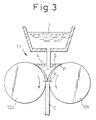
- the production of the thin sheet by a twin-roll continuous casting machine 11 of this kind is carried out as shown in Fig. 3.
- a molten metal L is poured from above and between a pair of casting rolls 12a and 12b disposed with a predetermined gap between them as shown in the drawing, and these casting rolls cooled inside with water 12a, 12b are rotated inwardly downward. Then, the molten metal L are brought into contact with the casting rolls 12a, 12b and is cooled, and is solidified as the solidified shell S in an arcuate form on the surface of each casting roll 12a, 12b.
- Each solidified shell S is brought close to the other with the revolution of the casting rolls 12a, 12b and is pressed at the minimum portion of the roll gap (hereinafter referred to as the "roll kiss point") into a casting C having a predetermined thickness.
- the casting C is pulled down from between the casting rolls 12a, 12b.
- solidification start point the point F (hereinafter referred to as the "solidification start point") at which the molten metal L comes into contact with each casting roll 12a, 12b that solidification of the solidified shell S starts.
- solidification start point the point F at which the molten metal L comes into contact with each casting roll 12a, 12b that solidification of the solidified shell S starts.
- Each solidified shell S which starts solidifying from the solidification start point F of each casting roll 12a, 12b continues to grow till the roll kiss point, and at this roll kiss point, each solidified shell S is rolled into the casting C having a predetermined thickness.
- a runner box encompassed by a frame is defined between a pair of water cooling rolls and a tundish, and the upper surface of a molten steel runner box frame is brought into close contact with the bottom surface of said tundish so that an iron hydrostatic pressure of the molten steel level inside said tundish is allowed to act on the solidified shells formed on the pair of said water cooling rolls.
- this process can obtain a thin cast strip having a casting thickness equivalent to that of a hot-rolled steel sheet obtained through existing rough rolling and finish rolling, at the time of casting, the process can eliminate the hot rolling step according to the prior art and can drastically reduce the cost of production.
- the steel sheet in the form of the cast strip as it is involves the problem that it is inferior in the aspect of the material.
- the casting so produced is used, in the as-cast state, as the product. Therefore, the crystal grain size is great, and both elongation and machinability are low. In other words, satisfactory mechanical strength cannot be obtained. Further, because scales of about 100 ⁇ m adhere to the surface of the thin sheet casting as-cast, the surface of the casting is rough and coarse.
- the gist of the invention disclosed in this prior art resides in the following point.
- heattreatment of cooling a metal thin sheet so casted to a temperature below an A 1 transformation point and then heating it again to a temperature above an A 3 transformation point or heating and holding it at said A 3 transformation point and again cooling it to a temperature below the A 1 transformation point is repeated at least twice in an in-line state.
- JP-A-60-83745 discloses a method of making the texture fine by imparting several times hot-rolling to the casting at a total reduction ratio of at least 20%.
- the crystal grain size is converted to a fine grain size by conducting cooling to the ferrite ( ⁇ ) zone immediately after solidification and heating to the austenite ( ⁇ ) zone.
- ⁇ ferrite
- ⁇ austenite
- JP-A-01-166864 discloses a twin-roll type continuous casting process, however this reference discloses nothing on in-line roiling process and a specific oxygen concentration in combination with a reduction ratio to obtain an improved grain size and surface roughness.
- hot rolling is used more preferably than cold rolling so as to prevent the increase of the entire length of the machine.
- the object of the present invention is to provide a method for reducing the fluctuation of the material in a common steel sheet equivalent to a hot rolled steel sheet produced from the thin cast strip as a starting material, which is thought to be inferior in the characteristics of the material compared with the present hot rolled steel sheet.
- the twin-roll continuous casting method of the present invention after the casting is solidified and temperature-controlled by the pair of water cooling casting rolls, it is rolled to a predetermined sheet thickness by the in-line rolling mill.
- the rolling temperature of in-line rolling is regulated to the temperature range in which the austenite structure exists in the matrix of the casting, and the reduction ratio is set to from 5 to 50%.
- the temperature range in which the austenite structure exists in the matrix of the casting is concretely a temperature of 850°C to less than 1,350°C, and the reason why the temperature is regulated to such a temperature range is to uniformly and finely reduce the crystal grain size of the casting to a fine grain size by a suitable rolling force.
- the rolling temperature is less than 850°C, the rolling force becomes great and the recrystallization time gets elongated. Therefore, the production line must be elongated.
- the rolling temperature is less than 850°C, it is possible that a ferrite transformation occurs and a final structure becomes a worked structure, with the result that the elongation remarkably lowers.
- the rolling temperature is higher than 1,350°C, on the other hand, the effect of uniforming the grain size can be obtained, but due to the high temperature, the crystal grains grow after rolling and the refining effect drops.
- the preferable range of the rolling temperature is 900 to less than 1,250°C in the present invention.
- the reason why the reduction ratio is set to 5 to 50% is to obtain a strip having a desired surface roughness, a crystal grain size and elongation but free from processing skin roughness.
- the reduction ratio is less than 5%
- the surface roughness and the crystal grain size become great
- the elongation drops and processing skin roughness occurs.
- variance of the as-cast materials cannot be reduced.
- a very small fluctuation of the sheet thickness and internal defects such as shrinkage cavity of the ascasted material cannot be eliminated, and variance of the materials occurs.
- the reduction ratio exceeds 50% the surface roughness becomes nonuniform and accuracy of the sheet thickness also often is lowered due to strong working.
- the inert gas atmosphere When the inert gas atmosphere is secured from the casting rolls to the entry side of the in-line rolling mill, high temperature oxidation of the casting can be prevented.
- the atmosphere is an inert gas atmosphere of an oxygen concentration of not higher than 2%, roughness of scales adhering to the surface of the casting can be extremely lowered, and a strip with sound surface quality, e.g. small surface roughness, can be obtained.
- Fig. 7 shows the relationship between a reduction ratio % and a surface roughness Rt of the casting.
- the figure shows a result in C: 0.04% and in-line rolling temperature: 1,100°C.
- the surface roughness Rt increases with the reduction ratio increment, with the result that the surface roughness is inferior than that in non in-line rolling.
- the reduction ratio effect is small. If the reduction ratio will be selected in an appropriate range, the surface roughness Rt of around 1/2 of that in non in-line rolling can be obtained.
- the casting machine is equipped with the in-line rolling mill for rolling the casting solidified by the pair of water cooling casting rolls into a predetermined sheet thickness.
- a thermometer for measuring the temperature of the casting immediately after solidification and a temperature regulator for regulating the temperature of the casting on the basis of the measurement value to the temperature such that the austenite structure exists in the matrix of the casting are disposed on the entry side of the in-line rolling mill. This temperature regulation is executed by adjusting a distance to the rolling mill, that is by adjusting an existing time in the cut-off housing.
- the casting When the temperature of the casting immediately after solidification, which is measured by the thermometer, is lower than the temperature range in which the austenite structure exists in the matrix of the casting, the casting may be heated by other means, e.g. a heater, to this temperature range and is then rolled by the in-line rolling mill.
- the casting When the temperature of the casting is higher than the temperature range in which the austenite structure exists in the matrix of the casting, the casting may be cooled by other means, e.g. a cooler, to the temperature range described above and is then rolled by the in-line rolling mill.
- the reduction ratio is set to 5 to 50%, a strip having a desired surface roughness, crystal grain size and elongation but devoid of ridging due to working can be obtained.
- the method for producing a steel sheet according the present process has been accomplished by finding that these characteristics of the material is improved and the variance of the material is remarkably reduced due to the one pass additive rolling of hot rolling after solidifying. After the rolling, it is desirably that the strip is water cooled and coiled at 500 to 700°C as same as the present hot rolling process. On the other hand, a subsequent process of pickling, skin pass rolling, etc. may be conducted according to the present hot rolled steel sheet.
- the variance of the material is shown by standard deviation ⁇ which is calculated from statistics processing of the overall elongation variance, at the time of executing JIS No. 5 tensile test. And a technical feature of the material in the present invention is within 5% of the standard deviation of the overall elongation.
- Carbon is the most important element for determining the strength of the ordinary steel, and its amount of addition may be suitably selected in accordance with a desired strength.
- Silicon too, is added in a suitable amount as a solid solution reinforcement element in the ordinary steel. However, when its amount exceeds 1.5%, its pickling property will be deteriorated. Therefore, the amount is preferably not greater than 1.5%.
- Manganese too, is added to the ordinary steel as a reinforcement element in the same way as C and Si. Generally, Mn is added in an amount at least five times the amount of sulfur in order to prevent hot brittleness resulting from S. However, from the aspect of weldability, the amount of Mn is preferably not greater than 2%.
- the amounts of phosphorous and sulfur are as small as possible, but no problem substantially occurs so long as their amount is not greater than 0.05% because unnecessary ultra-low phosphoration and ultra-low sulfurization will invite the cost of increase during the steel production process.
- elements contained in the steel are not particularly limited, either, in the present invention.
- trace amounts of Nb, Ti, V, B, etc. are added to the steel in order to improve the mechanical properties of the steel material such as strength and ductility, but the present invention are not at all affected by the addition of these elements.
- elements such as Cu, Sn, Cr, Ni, etc., mix as unavoidable elements, but the present invention is not at all impeded by the presence/absence of these elements.
- FIG. 1 is a schematic side view showing an embodiment of the twin-roll continuous casting machine according to the present invention.
- a pair of casting rolls 2a and 2b each equipped with a water cooling function are disposed with a predetermined gap between them as shown in the drawing.
- Side weirs 3 are disposed at both end portions of these casting rolls 2a, 2b, and a hot well 4 for storing a molten metal L is formed at the portion defined by these members.
- the molten metal L is charged from above into the hot well 4.
- the molten metal L is brought into contact with the casting rolls 2a, 2b, is cooled by water, and is solidified in an arcuate form on the surface of each casting roll 2a, 2b, as a solidified shell S.
- Each solidified shell S is brought close to the other with the rotation of the casting rolls 2a, 2b, is bonded at a roll kiss point K and is converted to a casting C having a predetermined thickness. The casting C is then pulled out downward from between the casting rolls 2a, 2b.
- An in-line rolling mill 5 for rolling the solidified casting C into a predetermined sheet thickness by hot rolling is provided on the downstream side of the casting rolls 2a, 2b.
- An ordinary rolling mill is used for this in-line rolling mill, but because a rolling ratio of from 5 to 50% is employed for the sheet thickness of the casting C, a rolling mill having such a reduction capacity is used.
- thermometer 6 for measuring the temperature of the casting C immediately after solidification and a temperature regulator 7 for regulating the temperature of the casting C within the temperature range in which an austenite structure ( ⁇ ) exists in the matrix on the basis of the measurement value are disposed on the entry side of the in-line rolling mill 5.
- a thermo-couple of platinum-platinum rhodium (Pt-Rh) for example, a thermometer capable of measuring the temperature within the range of from about 700 to about 1,500°C is used as the thermometer 6 described above.
- a heater 7a such as a high frequency induction heater or a warmer and/or a cooler 7b such as a water cooler is used as the temperature regulator 7.
- the other of the warmer is preferably a steel cover, etc. pasted innerside by refractories (e.g. fabric kaolin).
- the other of the heater is preferably a gas burner, etc.
- the other of the cooler is preferably a movable roll for adjusting cooling due to time increment during transferring, a pneumato-hydato cooler, etc.
- the present invention does not restrict those.
- the regulator 7 heats or cools the casting C and regulates the rolling temperature.
- the temperature of the casting C is lower than 850°C
- the casting C is heated by the heater 7a to 850°C but less than 1,350°C and is then rolled by the in-line rolling mill 5.
- the temperature of the casting C is higher than 1,350°C
- the casting is cooled by the cooler 7b to the temperature ranging from 850°C to less than 1,350°C, and is then rolled by the in-line rolling mill 5.
- the thin casting C rolled by the in-line rolling mill 5 is sequentially taken up by a coiler 8 disposed on the downstream side of the in-line rolling mill 5.
- An air-cut-off housing 9 is disposed from the casting rolls 2a, 2b to the entry side of the in-line rolling mill 5 in such a manner as to encompass the conveyor line of the casting C.
- An exhaust apparatus (not shown) for exhausting the inside of this air-cut-off housing 9 and a gas feeder (not shown) for supplying an inert gas such as argon (Ar), nitrogen (N 2 ), etc., into the housing 9 are connected to the air-cut-off housing 9.
- the casting rolls 2a, 2b of the twin-roll continuous casting machine 1 are shaped into a roll width of 350 mm and a roll diameter of 400 mm ⁇ , and are Cu rolls of an internal water cooling system.
- the casting condition is set to a casting rate of 30 m/min and a casting sheet thickness of 3.0 mm.
- the inside of the air-cut-off housing 9 is set to an inert gas atmosphere of 1% O 2 .
- the in-line rolling mill 5 is set to 2 stages, one stage and a work roll diameter of 300 mm ⁇ .
- a low carbon aluminum killed steel (0.04% C) is used as the casting material.
- the casting is cooled with water and is taken up at 650°C.
- the results of the experiments are tabulated in Table 1.
- the results of the experiments were based on the standard of approval stipulating the surface roughness of not greater than 20 ⁇ m, the crystal grain size of 20 to 30 ⁇ m, the strength of at least 36 kgf/mm 2 , elongation of at least 34% and the working skin roughness (ridging) of non-occurrence of seam due to ridging.
- the strength and the elongation 35 JIS 5 tensile testpieces were prepared from the resulting steel sheet and were subjected to the tensile test, and the total elongation so obtained were subjected to statistic processing so as to determine the mean value and the standard deviation.
- the approved value (below 20 ⁇ m) of the surface roughness was obtained at the reduction ratio of 5 to 50%.
- the approved value (20 to 30 ⁇ m) of the crystal grain size was obtained at the reduction ratio of 5 to 70%.
- the approved value (at least 34%) of the elongation was obtained at the reduction ratio of 5 to 70%, and the approved value (none) of the working skin roughness (ridging) was obtained at the reduction ratio of 5 to 70%.
- the strip having the desired surface roughness (not greater than 20 ⁇ m), the crystal grain size (20 to 30 ⁇ m) and the elongation (at least 34%) but devoid of the working skin roughness (ridging) could be obtained by rolling the casting C of the low carbon aluminum killed steel (0.04% C) at the reduction temperature of 1,100°C and at the reduction ratio of 5 to 50%.
- the casting material of the first embodiment is changed. More concretely, the second embodiment used a medium carbon aluminum killed steel (0.13% C), and the rest of the construction were the same as those of the first embodiment.
- the approved value (not greater than 20 ⁇ m) of the surface roughness was obtained at the reduction ratio of 5 to 50%, and the approved value (20 to 30 ⁇ m) of the crystal grain size was obtained at the reduction ratio of 10 to 50%.
- the approved value (at least 34%) of the elongation was obtained at the reduction ratio of 10 to 70%, and the approved value (none) of the working surface roughness (ridging) was obtained at the reduction ratio of 5 to 70%.
- the rolling temperature in the first embodiment was changed, and the rest of the conditions were the same as those of the first embodiment.
- the approved value (not greater than 20 ⁇ m) of the surface roughness could be obtained at the reduction ratio of 5 to 50%, and the approved value (20 to 30 ⁇ m) of the crystal grain size could be obtained at the reduction ratio of 20 to 70%.
- the approved value (at least 34%) of the elongation could be obtained at the reduction ratio of 10 to 70%, and the approved value (none) of the ridging could be obtained at the reduction ratio of 5 to 70%.
- a strip having the desired surface roughness (not greater than 20 ⁇ m), the crystal grain size (20 to 30 ⁇ m) and the elongation (at least 34%) but devoid of the ridging could be obtained by rolling the casting C of the low carbon aluminum killed steel (0.04% C) at a rolling temperature of 850°C and the reduction ratio of 20 to 50% by the in-line rolling mill 5.
- the rolling temperature in the first embodiment was changed, and the rest of the conditions were the same as those of the first embodiment.
- the approved value (not greater than 20 ⁇ m) could be obtained at the reduction ratio of 5 to 50%, and the approved value (20 to 30 ⁇ m) of the crystal grain size could be obtained at the reduction ratio of 5 to 70%.
- the approved value (at least 34%) of the elongation could be obtained at the reduction ratio of 5 to 70%, and the approved value (none) of the ridging could be obtained at the reduction ratio of 5 to 70%.
- a strip having the desired surface roughness (not greater than 20 ⁇ m), the crystal grain size (20 to 30 ⁇ m) and the elongation (at least 34%) but devoid of the working skin roughness could be obtained by rolling the casting C of the low carbon aluminum killed steel (0.04% C) at the rolling temperature of 1,300°C and the reduction ratio of 5 to 50% by the in-line rolling mill 5.
- the first Comparative Example which was carried out in order to confirm the function and effects of the twin-roll continuous casting methods of the first to fourth embodiments, will be explained.
- the rolling temperature in the first embodiment was changed. More concretely, comparative experiments were carried out at a rolling temperature of 750°C and reduction ratios of 0%, 2%, 5%, 10%, 20%, 30%, 40%, 50%, 60% and 70% so as to confirm the surface roughness ( ⁇ m), the crystal grain size ( ⁇ m), the strength (kgf/mm 2 ), the elongation (%) and the working skin roughness (ridging).
- the rolling temperature in the first embodiment was changed. More concretely, experiments were carried out at a rolling temperature of 1,350°C and reduction ratios of 0%, 2%, 5%, 10%, 20%, 30%, 40%, 50%, 60% and 70% so as to confirm the surface roughness ( ⁇ m), the crystal grain size ( ⁇ m), the strength (kgf/mm 2 ), the elongation (%) and the working skin roughness (ridging).
- the twin-roll continuous casting method according to the present invention can produce the product thin sheet by directly conducting hot rolling during the transfer of the casting C without effecting cold rolling as described above, it can drastically reduce the cost of equipment as well as the cost of production.
- the temperature range of from 850°C to less than 1,350°C of the rolling temperature described above is the temperature zone in which the austenite structure ( ⁇ ) exists in the matrix of the casting C and more concretely, it is the range where the ferrite structure ( ⁇ ) and the austenite structure ( ⁇ ) co-exist or a single layer zone of the austenite structure ( ⁇ ).
- the twin-roll continuous casting method according to the present invention is directed to the carbon steel having the carbon content within the range of 0.0005% to 1.0% C.
- FIG. 2 is a graph showing the relation between the mean crystal grain size and the crystal grain size number.
- the carbon steels having a grain size number of 5 or more are generally called "fine grain steel” (refer to "Lectures on Iron and Steel Technologies, New Edition", Vol. 3, Properties of Steel Materials and Tests, pp. 414 - 419, edited by The Iron and Steel Institute of Japan). It can be seen that when the crystal grain size is below 30 ⁇ m, the steel is a fine grain steel having a grain size number of 7.5 or more.
- the twin-roll continuous casting method according to the present invention can increase the ferrite grain size to the grain size number of at least 7.5 in the as-cast casting C by applying mild rolling at a reduction ratio of 5 to 50% during the transfer of the casting C, and can thus produce the thin sheet casting having the fine grain texture which is homogeneous from the surface to the inside of the casting and in both transverse and longitudinal directions.
- the internal atmosphere of the air-cut-off housing 9 in the first embodiment was changed. More concretely, the inside of the air-cut-off housing 9 was set to an inert gas atmosphere of 2% O 2 , and the rest of the conditions were the same as those of the first embodiment.
- the approved value (not greater than 20 ⁇ m) of the surface roughness could be obtained at the reduction ratio of 5 to 50%, and the approved value (20 to 30 ⁇ m) of the crystal grain size could be obtained at the reduction ratio of 5 to 70%.
- the approved value (36 kgf/mm 2 or more) of the strength could be obtained at all the reduction ratios, and the approved value (at least 34%) of the elongation could be obtained at the reduction ratio of 5 to 70%.
- the approved value (none) of the ridging could be obtained at the reduction ratio of 5 to 70%.
- a strip having the desired surface roughness (not greater than 20 ⁇ m), the crystal grain size (20 to 30 ⁇ m) and the elongation (at least 34%) but devoid of the ridging could be obtained by rolling the casting C of the low carbon aluminum killed steel (0.04% C) at the rolling temperature of 1,100°C and at the reduction ratio of 5 to 50% by the in-line rolling mill 5 in the inert atmosphere of 2% O 2 .
- the third Comparative Example which was carried out to confirm the function and effect of the twin-roll continuous casting method of the fifth embodiment, will be explained.
- the internal atmosphere of the air-cut-off housing 9 in the fifth embodiment was changed. More concretely, the inside of the air-cut-off housing 9 was set to the inert gas atmosphere of 3% O 2 , and comparative experiments were carried out at a rolling temperature of 1,100°C and a reduction ratios of 0%, 2%, 5%, 10%, 20%, 30%, 40%, 50%, 60% and 70% so as to confirm the surface roughness ( ⁇ m), the crystal grain size ( ⁇ m), the strength (kgf/mm 2 ), the elongation (%) and the working skin roughness (ridging).
- the kind of the steel was a low carbon aluminum killed steel (0.04% C), the rolling temperature was 1,100°C, and the reduction ratios were 2%, 5%, 10% and 20%.
- the casting was cooled with water after rolling and was taken up at 650°C.
- the twin-roll continuous casting machine is shown as a side view in Fig. 4.
- the molten metal L is stored in a sectioned portion by the side weirs 3 and the casting rolls 2a and 2b, and said casting rolls rotate inwardly downward while being cooled with water.
- the casting C having a predetermined thickness is converted by bonding at roll kiss point and pulled out downward from between the casting rolls 2a and 2b.
- the air-cut-off housing 9 seals from delivery side of the casting rolls 2a and 2b to the in-line rolling mill 5. Nitrogen gas is fed through a nitrogen gas pipe 13 so as to hold inert gas atmosphere inside the air-cut-off housing 9.
- a loop detector 19 Inside the air-cut-off housing 9, a loop detector 19, a pinch roll 14, cooling zone 15 and a transfer roll 16 are disposed. More, in the delivery side of the air-cut-off housing 9, a pair of transfer roll in which one is a movable roll 17 and the other is a fixed roll 18 is disposed for adjusting the transfer distance. More, the casting temperature is measured by a thermometer 20 and the data is used for regulating a flow adjusting valve 22 of the cooling water W through a converter 21.
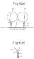
- Fig. 5(a) shows the air-cut-off housing 23 under the casting rolls
- Fig. 5(b) is a magnified view of A portion in Fig. 5(a).
- Fig. 6 is a front view of the air cut-off housing 23 under the casting rolls.
- the air-cut-off housing is disposed from the roll kiss point, the steel plate 24 at outside end portion is secured to maintain entirely sealing by pasting a fabric kaolin 25 thereon. More, the space between the steel plate 24 and the casting rolls is held in an inert atmosphere by sliding the fabric kaolin.
- a thin sheet having excellent mechanical strength, devoid of skin roughness and having excellent surface roughness could be obtained by refining homogeneously the crystal grains, and the cost of equipment can be reduced.
- the present invention basically relates to a method of producing a material corresponding to a hot-rolled sheet from a thin cast strip, the steel sheet produced by the present invention can become a cold-rolled blank, too, in view of the fact that existing cold-rolled steel sheets and their plated steel sheets are produced by using a hot-rolled steel sheet as the blank.
Abstract
Description
- This invention relates to a twin-roll continuous casting method and apparatus for conducting in-line rolling of a thin sheet casting during its transfer, and more particularly to an improved twin-roll continuous casting method which improves the rolling conditions in in-line rolling and a twin-roll continuous casting machine used for this method.
- This invention relates to a production method of an ordinary steel sheet corresponding to a hot-rolled steel sheet by using a cast strip produced by the present method as a starting material, and more particularly to a method of reducing variance of materials typified by elongation of the steel material.
- Generally, a twin-roll continuous casting machine is known as an apparatus applying a Bessemer type continuous casting method, and is used for producing a thin metal sheet by pouring a molten metal between a pair of watercooled casting rolls and solidifying it.
- The production of the thin sheet by a twin-roll
continuous casting machine 11 of this kind is carried out as shown in Fig. 3. A molten metal L is poured from above and between a pair ofcasting rolls water casting rolls casting roll casting rolls casting rolls - In this case, it is the point F (hereinafter referred to as the "solidification start point") at which the molten metal L comes into contact with each
casting roll casting roll - An associated technology for winding the casting C so produced onto a coiler as-cast and shipping the product is described in JP-A-58-359.
- The gist of the invention disclosed in this prior art resides in the following point. In the method, a runner box encompassed by a frame is defined between a pair of water cooling rolls and a tundish, and the upper surface of a molten steel runner box frame is brought into close contact with the bottom surface of said tundish so that an iron hydrostatic pressure of the molten steel level inside said tundish is allowed to act on the solidified shells formed on the pair of said water cooling rolls.
- Because this process can obtain a thin cast strip having a casting thickness equivalent to that of a hot-rolled steel sheet obtained through existing rough rolling and finish rolling, at the time of casting, the process can eliminate the hot rolling step according to the prior art and can drastically reduce the cost of production. However, the steel sheet in the form of the cast strip as it is involves the problem that it is inferior in the aspect of the material.
- In other words, according to the invention of the prior art, the casting so produced is used, in the as-cast state, as the product. Therefore, the crystal grain size is great, and both elongation and machinability are low. In other words, satisfactory mechanical strength cannot be obtained. Further, because scales of about 100 µm adhere to the surface of the thin sheet casting as-cast, the surface of the casting is rough and coarse.
- Therefore, in order to finish the casting C so casted to the product, there are a method which removes the scales of the casting C after casting, rolls it into a predetermined sheet thickness by hot rolling and winds the resulting strip on a coiler, and another which removes the scales of the casting C after casting, rolls it into a predetermined sheet thickness by cold rolling, anneals the resulting strip and winds it up on the coiler to obtain the product.
- A method of finely refining the crystal grain size is described in JP-A-63-115654.
- The gist of the invention disclosed in this prior art resides in the following point. In the method, heattreatment of cooling a metal thin sheet so casted to a temperature below an A1 transformation point and then heating it again to a temperature above an A3 transformation point or heating and holding it at said A3 transformation point and again cooling it to a temperature below the A1 transformation point is repeated at least twice in an in-line state.
- JP-A-60-83745 discloses a method of making the texture fine by imparting several times hot-rolling to the casting at a total reduction ratio of at least 20%.
- These means all intend to improve the materials by making the metallic texture fine by utilizing recrystallization or transformation. As to factors other than such a metallic structure, the reasons why the materials of the steel sheet in the form of the thin cast strip are inferior have not been sufficiently clarified. When the materials of the thin cast strip are discussed, no prior art references inclusive of the references described above have ever made mention of fluctuation of the materials, that is, variance.
- In the invention disclosed in the prior art of JP-A-63-115654, the crystal grain size is converted to a fine grain size by conducting cooling to the ferrite (α) zone immediately after solidification and heating to the austenite (γ) zone. However, there remains the problem that the cost of equipment increases because the entire length of the metal thin sheet casting machine used is elongated.
- JP-A-01-166864 discloses a twin-roll type continuous casting process, however this reference discloses nothing on in-line roiling process and a specific oxygen concentration in combination with a reduction ratio to obtain an improved grain size and surface roughness.
- By the way, in order to obtain a product from the casting C by in-line rolling, hot rolling is used more preferably than cold rolling so as to prevent the increase of the entire length of the machine.
- Generally, in a case of an inferior material, one is inferior in the characteristics itself and the other is inferior in the fluctuation of the characteristics. In the latter case, though the fluctuation of the material is a predominant problem in a discussion of the steel material since the lowest limit value of the property of the material should be adopted due to product liability as the property of the material, the thin cast strip produced by the process has not sufficiently be studied in view of the point.
- The object of the present invention is to provide a method for reducing the fluctuation of the material in a common steel sheet equivalent to a hot rolled steel sheet produced from the thin cast strip as a starting material, which is thought to be inferior in the characteristics of the material compared with the present hot rolled steel sheet.
- In view of the problem described above, it is an object of the present invention to provide a twin-roll continuous casting method, which can produce a thin sheet having excellent mechanical strength by reducing homogeneously the crystal grain size to a fine grain size by in-line hot rolling and having excellent surface roughness free from skin roughness, and which can reduce the cost of equipment.
- The above objects are solved by the features specified in the claims.
- The invention is described in more detail in connection with the drawings, in which:
- Fig. 1 is a schematic side view showing a twin-roll continuous casting machine according to one embodiment of the present invention;
- Fig. 2 is a graph showing the relation between a mean crystal grain size and a crystal grain number;
- Fig. 3 is a side view showing the principal portions of a conventional twin-roll continuous casting machine;
- Fig. 4 is a side view showing a cut-off housing for establishing therein an inert atmosphere;
- Fig. 5(a) is a side view showing a cut-off housing in the vicinity of the twin-roll;
- Fig. 5(b) is a detail view of A portion in Fig. 5(a);
- Fig. 6 is a front view showing a cut-off housing in the vicinity of the twin-roll; and
- Fig. 7 is a graph showing the relation between a reduction ratio and a surface roughness.
-
- According to the construction of the twin-roll continuous casting method of the present invention, after the casting is solidified and temperature-controlled by the pair of water cooling casting rolls, it is rolled to a predetermined sheet thickness by the in-line rolling mill. In other words, the rolling temperature of in-line rolling is regulated to the temperature range in which the austenite structure exists in the matrix of the casting, and the reduction ratio is set to from 5 to 50%.
- The temperature range in which the austenite structure exists in the matrix of the casting is concretely a temperature of 850°C to less than 1,350°C, and the reason why the temperature is regulated to such a temperature range is to uniformly and finely reduce the crystal grain size of the casting to a fine grain size by a suitable rolling force. In other words, when the rolling temperature is less than 850°C, the rolling force becomes great and the recrystallization time gets elongated. Therefore, the production line must be elongated.
- Moreover, when the rolling temperature is less than 850°C, it is possible that a ferrite transformation occurs and a final structure becomes a worked structure, with the result that the elongation remarkably lowers.
- When the rolling temperature is higher than 1,350°C, on the other hand, the effect of uniforming the grain size can be obtained, but due to the high temperature, the crystal grains grow after rolling and the refining effect drops.
- Moreover, the preferable range of the rolling temperature is 900 to less than 1,250°C in the present invention.
- The reason why the reduction ratio is set to 5 to 50% is to obtain a strip having a desired surface roughness, a crystal grain size and elongation but free from processing skin roughness. In other words, when the reduction ratio is less than 5%, the surface roughness and the crystal grain size become great, the elongation drops and processing skin roughness occurs. Further, when the reduction ratio was less than 5%, variance of the as-cast materials cannot be reduced. In other words, a very small fluctuation of the sheet thickness and internal defects such as shrinkage cavity of the ascasted material cannot be eliminated, and variance of the materials occurs. On the other hand, when the reduction ratio exceeds 50%, the surface roughness becomes nonuniform and accuracy of the sheet thickness also often is lowered due to strong working.
- When the inert gas atmosphere is secured from the casting rolls to the entry side of the in-line rolling mill, high temperature oxidation of the casting can be prevented. In this case, when the atmosphere is an inert gas atmosphere of an oxygen concentration of not higher than 2%, roughness of scales adhering to the surface of the casting can be extremely lowered, and a strip with sound surface quality, e.g. small surface roughness, can be obtained.
- Fig. 7 shows the relationship between a reduction ratio % and a surface roughness Rt of the casting. The figure shows a result in C: 0.04% and in-line rolling temperature: 1,100°C. In air atmosphere (21% O2), the surface roughness Rt increases with the reduction ratio increment, with the result that the surface roughness is inferior than that in non in-line rolling.
- However, in not higher than 5% of atmosphere oxygen, the reduction ratio effect is small. If the reduction ratio will be selected in an appropriate range, the surface roughness Rt of around 1/2 of that in non in-line rolling can be obtained.
- On the other hand, according to the construction of the twin-roll continuous casting machine, the casting machine is equipped with the in-line rolling mill for rolling the casting solidified by the pair of water cooling casting rolls into a predetermined sheet thickness. A thermometer for measuring the temperature of the casting immediately after solidification and a temperature regulator for regulating the temperature of the casting on the basis of the measurement value to the temperature such that the austenite structure exists in the matrix of the casting are disposed on the entry side of the in-line rolling mill. This temperature regulation is executed by adjusting a distance to the rolling mill, that is by adjusting an existing time in the cut-off housing.
- When the temperature of the casting immediately after solidification, which is measured by the thermometer, is lower than the temperature range in which the austenite structure exists in the matrix of the casting, the casting may be heated by other means, e.g. a heater, to this temperature range and is then rolled by the in-line rolling mill. When the temperature of the casting is higher than the temperature range in which the austenite structure exists in the matrix of the casting, the casting may be cooled by other means, e.g. a cooler, to the temperature range described above and is then rolled by the in-line rolling mill. In this instance, if the reduction ratio is set to 5 to 50%, a strip having a desired surface roughness, crystal grain size and elongation but devoid of ridging due to working can be obtained.
- When an air-cut-off housing is formed between the casting rolls and the entry side of the in-line rolling mill and the inside of this housing is kept in the inert gas atmosphere, high temperature oxidation of the casting can be prevented.
- The method for producing a steel sheet according the present process has been accomplished by finding that these characteristics of the material is improved and the variance of the material is remarkably reduced due to the one pass additive rolling of hot rolling after solidifying. After the rolling, it is desirably that the strip is water cooled and coiled at 500 to 700°C as same as the present hot rolling process. On the other hand, a subsequent process of pickling, skin pass rolling, etc. may be conducted according to the present hot rolled steel sheet.
- In the present invention, the variance of the material is shown by standard deviation σ which is calculated from statistics processing of the overall elongation variance, at the time of executing JIS No. 5 tensile test. And a technical feature of the material in the present invention is within 5% of the standard deviation of the overall elongation.
- Although the chemical components in the present invention are not particularly limited, the inventors of the present invention have acquired the following observation. Carbon is the most important element for determining the strength of the ordinary steel, and its amount of addition may be suitably selected in accordance with a desired strength.
- Silicon, too, is added in a suitable amount as a solid solution reinforcement element in the ordinary steel. However, when its amount exceeds 1.5%, its pickling property will be deteriorated. Therefore, the amount is preferably not greater than 1.5%.
- Manganese, too, is added to the ordinary steel as a reinforcement element in the same way as C and Si. Generally, Mn is added in an amount at least five times the amount of sulfur in order to prevent hot brittleness resulting from S. However, from the aspect of weldability, the amount of Mn is preferably not greater than 2%.
- Basically, the amounts of phosphorous and sulfur are as small as possible, but no problem substantially occurs so long as their amount is not greater than 0.05% because unnecessary ultra-low phosphoration and ultra-low sulfurization will invite the cost of increase during the steel production process.
- Other elements contained in the steel are not particularly limited, either, in the present invention. For example, trace amounts of Nb, Ti, V, B, etc., are added to the steel in order to improve the mechanical properties of the steel material such as strength and ductility, but the present invention are not at all affected by the addition of these elements. On the other hand, when the scrap is used as the primary raw material, elements such as Cu, Sn, Cr, Ni, etc., mix as unavoidable elements, but the present invention is not at all impeded by the presence/absence of these elements.
- Preferred embodiments of the twin-roll continuous casting method and the apparatus therefor according to the present invention will be described in detail with reference to the accompanying drawings.
- Figure 1 is a schematic side view showing an embodiment of the twin-roll continuous casting machine according to the present invention. In the twin-roll
continuous casting machine 1 of this embodiment, a pair of casting rolls 2a and 2b each equipped with a water cooling function are disposed with a predetermined gap between them as shown in the drawing.Side weirs 3 are disposed at both end portions of these castingrolls hot well 4 for storing a molten metal L is formed at the portion defined by these members. - The molten metal L is charged from above into the
hot well 4. When the casting rolls 2a, 2b are rotated inwardly downward while being cooled with water, the molten metal L is brought into contact with the casting rolls 2a, 2b, is cooled by water, and is solidified in an arcuate form on the surface of each castingroll - An in-
line rolling mill 5 for rolling the solidified casting C into a predetermined sheet thickness by hot rolling is provided on the downstream side of the casting rolls 2a, 2b. An ordinary rolling mill is used for this in-line rolling mill, but because a rolling ratio of from 5 to 50% is employed for the sheet thickness of the casting C, a rolling mill having such a reduction capacity is used. - A
thermometer 6 for measuring the temperature of the casting C immediately after solidification and atemperature regulator 7 for regulating the temperature of the casting C within the temperature range in which an austenite structure (γ) exists in the matrix on the basis of the measurement value are disposed on the entry side of the in-line rolling mill 5. Besides a thermo-couple of platinum-platinum rhodium (Pt-Rh), for example, a thermometer capable of measuring the temperature within the range of from about 700 to about 1,500°C is used as thethermometer 6 described above. A heater 7a such as a high frequency induction heater or a warmer and/or a cooler 7b such as a water cooler is used as thetemperature regulator 7. - The other of the warmer is preferably a steel cover, etc. pasted innerside by refractories (e.g. fabric kaolin). The other of the heater is preferably a gas burner, etc. More, the other of the cooler is preferably a movable roll for adjusting cooling due to time increment during transferring, a pneumato-hydato cooler, etc. However, the present invention does not restrict those.
- More concretely, when the temperature of the casting C immediately after solidification is measured by the
thermometer 6 and the measurement value is out of the temperature zone in which the austenite structure (γ) exists in the matrix of the casting C, theregulator 7 heats or cools the casting C and regulates the rolling temperature. In other words, when the temperature of the casting C is lower than 850°C, the casting C is heated by the heater 7a to 850°C but less than 1,350°C and is then rolled by the in-line rolling mill 5. On the other hand, when the temperature of the casting C is higher than 1,350°C, the casting is cooled by the cooler 7b to the temperature ranging from 850°C to less than 1,350°C, and is then rolled by the in-line rolling mill 5. - The thin casting C rolled by the in-
line rolling mill 5 is sequentially taken up by acoiler 8 disposed on the downstream side of the in-line rolling mill 5. - An air-cut-off
housing 9 is disposed from the casting rolls 2a, 2b to the entry side of the in-line rolling mill 5 in such a manner as to encompass the conveyor line of the casting C. An exhaust apparatus (not shown) for exhausting the inside of this air-cut-offhousing 9 and a gas feeder (not shown) for supplying an inert gas such as argon (Ar), nitrogen (N2), etc., into thehousing 9 are connected to the air-cut-offhousing 9. - Next, the twin-roll continuous casting method of the first embodiment which is practiced by using the twin-roll
continuous casting machine 1 described above will be explained. The casting rolls 2a, 2b of the twin-rollcontinuous casting machine 1 are shaped into a roll width of 350 mm and a roll diameter of 400 mm, and are Cu rolls of an internal water cooling system. The casting condition is set to a casting rate of 30 m/min and a casting sheet thickness of 3.0 mm. The inside of the air-cut-offhousing 9 is set to an inert gas atmosphere of 1% O2. The in-line rolling mill 5 is set to 2 stages, one stage and a work roll diameter of 300 mm. A low carbon aluminum killed steel (0.04% C) is used as the casting material. The casting is cooled with water and is taken up at 650°C. - Experiments were carried out under the conditions described above by the twin-roll continuous casting method of the first embodiment at the rolling temperature of 1,100°C for the in-
line rolling mill 5 at reduction ratios of 0%, 2%, 5%, 10%, 20%, 30%, 40%, 50%, 60% and 70% so as to confirm the surface roughness (µm), the crystal grain size (µm), strength (kgf/mm2), elongation (%) and working skin roughness (ridging). - The results of the experiments are tabulated in Table 1. By the way, the results of the experiments were based on the standard of approval stipulating the surface roughness of not greater than 20 µm, the crystal grain size of 20 to 30 µm, the strength of at least 36 kgf/mm2, elongation of at least 34% and the working skin roughness (ridging) of non-occurrence of seam due to ridging. As to the strength and the elongation, 35
JIS 5 tensile testpieces were prepared from the resulting steel sheet and were subjected to the tensile test, and the total elongation so obtained were subjected to statistic processing so as to determine the mean value and the standard deviation.Reduction ratio (%) Surface roughness (µm) Grain size (µm) Target strength kgf/mm2 Elongation (%) Working skin roughness (ridging) 0 70 100 36 17 Occurred 2 40 75 36 26 Occurred 5 18 30 36 34 None 10 15 26 36 43 None 20 13 22 36 43 None 30 12 21 36 43 None 40 12 21 36 43 None 50 19 21 36 43 None 60 22 21 36 43 None 70 26 21 36 43 None - As shown in Table 1, the approved value (below 20 µm) of the surface roughness was obtained at the reduction ratio of 5 to 50%. The approved value (20 to 30 µm) of the crystal grain size was obtained at the reduction ratio of 5 to 70%. The approved value (at least 34%) of the elongation was obtained at the reduction ratio of 5 to 70%, and the approved value (none) of the working skin roughness (ridging) was obtained at the reduction ratio of 5 to 70%.
- In other words, it was confirmed that in the twin-roll continuous casting method of the first embodiment, the strip having the desired surface roughness (not greater than 20 µm), the crystal grain size (20 to 30 µm) and the elongation (at least 34%) but devoid of the working skin roughness (ridging) could be obtained by rolling the casting C of the low carbon aluminum killed steel (0.04% C) at the reduction temperature of 1,100°C and at the reduction ratio of 5 to 50%.
- In this second embodiment, the casting material of the first embodiment is changed. More concretely, the second embodiment used a medium carbon aluminum killed steel (0.13% C), and the rest of the construction were the same as those of the first embodiment.
- Experiments were carried out under the condition described above by the twin-roll continuous casting method of the second embodiment at a rolling temperature of the in-
line rolling mill 5 at 1,100°C and reduction ratios of 0%, 2%, 5%, 10%, 20%, 30%, 40%, 50%, 60% and 70% so as to confirm the surface roughness (µm), the crystal grain size (µm), the strength (Kgf/mm2), the elongation (%) and working skin roughness (ridging). - The results of the experiments are tabulated in Table 2. The results of the judgement were based on the same standard of approval with the exception that the strength was set to at least 40 kgf/mm2.
Reduction ratio (%) Surface roughness (µm) Grain size (µm) Target strength kgf/mm2 Elongation (%) Working skin roughness (ridging) 0 72 105 40 15 Occurred 2 42 74 40 20 Occurred 5 15 32 40 29 None 10 14 24 40 37 None 20 13 21 40 39 None 30 12 20 40 39 None 40 12 20 40 41 None 50 19 21 40 43 None 60 23 19 40 41 None 70 28 21 40 43 None - As tabulated in Table 2, the approved value (not greater than 20 µm) of the surface roughness was obtained at the reduction ratio of 5 to 50%, and the approved value (20 to 30 µm) of the crystal grain size was obtained at the reduction ratio of 10 to 50%. The approved value (at least 34%) of the elongation was obtained at the reduction ratio of 10 to 70%, and the approved value (none) of the working surface roughness (ridging) was obtained at the reduction ratio of 5 to 70%.
- In other words, it was confirmed that in the twin-roll continuous casting method of the second embodiment, that a strip having the desired surface roughness (not greater than 20 µm), the crystal grain size (20 to 30 µm) and the elongation (at least 34%) but devoid of the ridging could be obtained by rolling the casting C of the medium carbon aluminum killed steel (0.13% C) at the rolling temperature of 1,100°C and at the reduction ratio of 10 to 50% by the in-
line rolling mill 5. - In the third embodiment, the rolling temperature in the first embodiment was changed, and the rest of the conditions were the same as those of the first embodiment.
- More concretely, experiments were carried out by the twin-rolling continuous casting method of the third embodiment at a rolling temperature of the in-
line rolling mill 5 at 850°C and reduction ratios of 0%, 2%, 5%, 10%, 20%, 30%, 40%, 50%, 60% and 70% so as to confirm the surface roughness (µm), the crystal grain size (µm), the strength (kgf/mm2), the elongation (%) and working skin roughness (ridging). - The results were tabulated in Table 3. The same standard of approval as that of the first embodiment was used for the judgement of the results.
Reduction ratio (%) Surface roughness (µm) Grain size (µm) Target strength kgf/mm2 Elongation (%) Working skin roughness (ridging) 0 70 100 36 17 Occurred 2 50 80 36 24 Occurred 5 19 35 36 27 None 10 18 33 36 34 None 20 17 28 36 36 None 30 16 24 36 39 None 40 15 22 36 39 None 50 18 22 36 39 None 60 26 22 36 41 None 70 28 22 36 41 None - As tabulated in Table 3, the approved value (not greater than 20 µm) of the surface roughness could be obtained at the reduction ratio of 5 to 50%, and the approved value (20 to 30 µm) of the crystal grain size could be obtained at the reduction ratio of 20 to 70%. The approved value (at least 34%) of the elongation could be obtained at the reduction ratio of 10 to 70%, and the approved value (none) of the ridging could be obtained at the reduction ratio of 5 to 70%.
- In other words, it was confirmed that in the twin-rolling continuous casting method of the third embodiment, a strip having the desired surface roughness (not greater than 20 µm), the crystal grain size (20 to 30 µm) and the elongation (at least 34%) but devoid of the ridging could be obtained by rolling the casting C of the low carbon aluminum killed steel (0.04% C) at a rolling temperature of 850°C and the reduction ratio of 20 to 50% by the in-
line rolling mill 5. - In the fourth embodiment, the rolling temperature in the first embodiment was changed, and the rest of the conditions were the same as those of the first embodiment.
- More concretely, experiments were carried out by the twin-roll continuous casting method of the fourth embodiment at a rolling temperature of the in-
line rolling mill 5 at 1,300°C and reduction ratios of 0%, 2%, 5%, 10%, 20%, 30%, 40%, 50%, 60% and 70% so as to confirm the surface roughness (µm), the crystal grain size (µm), the strength (kgf/mm2), the elongation and the working skin roughness (ridging). - The results of the experiments were tabulated in Table 4. The same standard of approval as that of the first embodiment was used for the judgement of the results.
Reduction ratio (%) Surface roughness (µm) Grain size (µm) Target strength kgf/mm2 Elongation (%) Working skin roughness (ridging) 0 70 100 36 17 Occurred 2 30 78 36 24 Occurred 5 16 30 36 34 None 10 14 26 36 39 None 20 13 23 36 41 None 30 13 24 36 43 None 40 11 22 36 41 None 50 16 21 36 42 None 60 22 22 36 44 None 70 25 21 36 42 None - As tabulated in Table 4, the approved value (not greater than 20 µm) could be obtained at the reduction ratio of 5 to 50%, and the approved value (20 to 30 µm) of the crystal grain size could be obtained at the reduction ratio of 5 to 70%. The approved value (at least 34%) of the elongation could be obtained at the reduction ratio of 5 to 70%, and the approved value (none) of the ridging could be obtained at the reduction ratio of 5 to 70%.
- In other words, it was confirmed that in the twin-roll continuous casting method of the fourth embodiment, a strip having the desired surface roughness (not greater than 20 µm), the crystal grain size (20 to 30 µm) and the elongation (at least 34%) but devoid of the working skin roughness could be obtained by rolling the casting C of the low carbon aluminum killed steel (0.04% C) at the rolling temperature of 1,300°C and the reduction ratio of 5 to 50% by the in-
line rolling mill 5. - Next, the first Comparative Example, which was carried out in order to confirm the function and effects of the twin-roll continuous casting methods of the first to fourth embodiments, will be explained. In this first Comparative Example, the rolling temperature in the first embodiment was changed. More concretely, comparative experiments were carried out at a rolling temperature of 750°C and reduction ratios of 0%, 2%, 5%, 10%, 20%, 30%, 40%, 50%, 60% and 70% so as to confirm the surface roughness (µm), the crystal grain size (µm), the strength (kgf/mm2), the elongation (%) and the working skin roughness (ridging).
- The results of the experiments were tabulated in Table 5. The same standard of approval as that of the first embodiment was used for the judgement of the results.
Reduction ratio (%) Surface roughness (µm) Grain size (µm) Target strength kgf/mm2 Elongation (%) Working skin roughness (ridging) 0 70 100 36 17 Occurred 2 50 85 36 29 Occurred 5 19 45 36 26 Occurred 10 17 40 36 29 Occurred 20 16 37 36 30 Occurred 30 15 36 36 31 Occurred 40 15 32 36 31 Occurred 50 19 31 36 30 Occurred 60 27 31 36 31 Occurred 70 28 31 36 31 Occurred - As tabulated in Table 5, the elongation (%) dropped below 34% when the crystal grain size exceeded 30 µm at all the reduction ratios, the ridging occurred, and the resulting strips failed to pass the standard of judgement.
- In other words, in the first Comparative Example, even when the casting C of the low carbon aluminum killed steel (0.04% C) was rolled at the reduction ratios of 0 to 70% by the in-
line rolling mill 5, sound strips could not be obtained at the rolling temperature of 750°C. - In this second Comparative Example, the rolling temperature in the first embodiment was changed. More concretely, experiments were carried out at a rolling temperature of 1,350°C and reduction ratios of 0%, 2%, 5%, 10%, 20%, 30%, 40%, 50%, 60% and 70% so as to confirm the surface roughness (µm), the crystal grain size (µm), the strength (kgf/mm2), the elongation (%) and the working skin roughness (ridging).
- The results of the experiments were tabulated in Table 6. The same standard of approval as that of the first embodiment was used for the judgement of the results.
Reduction ratio (%) Surface roughness (µm) Grain size (µm) Target strength kgf/mm2 Elongation (%) Working skin roughness (ridging) 0 70 100 36 17 Occurred 2 31 88 36 20 Occurred 5 15 39 36 24 Occurred 10 13 35 36 26 Occurred 20 12 37 36 29 Occurred 30 13 36 36 30 Occurred 40 14 38 36 31 Occurred 50 18 35 36 32 Occurred 60 25 32 36 34 None 70 28 31 36 34 None - As tabulated in Table 6, the crystal grain size exceeded 30 µm at all the reduction ratios, the elongation dropped below 34% and the ridging occurred at the reduction ratios of 0 to 50%, and the resulting strips failed to pass the standard of judgement.
- In other words, in the second Comparative Example, even when the casting C of the low carbon aluminum killed steel (0.04% C) was rolled at the reduction ratios of 0 to 70% by the in-
line rolling mill 5, sound strips could not be obtained at the rolling temperature of 1,350°C. - As described above, it was found out by comparing the twin-roll continuous casting methods of the first to fourth embodiments with the first and second Comparative Examples that the strips having the desired surface roughness (not greater than 20 µm), the crystal grain size (20 to 30 µm) and the elongation (at least 34%) but devoid of the working skin roughness could be obtained by casting the castings C of the carbon steel at the rolling temperature of 850°C to less than 1,350°C and at the reduction ratios of 5 to 50% by the in-
line rolling mill 5. Because the twin-roll continuous casting method according to the present invention can produce the product thin sheet by directly conducting hot rolling during the transfer of the casting C without effecting cold rolling as described above, it can drastically reduce the cost of equipment as well as the cost of production. - The temperature range of from 850°C to less than 1,350°C of the rolling temperature described above is the temperature zone in which the austenite structure (γ) exists in the matrix of the casting C and more concretely, it is the range where the ferrite structure (α) and the austenite structure (γ) co-exist or a single layer zone of the austenite structure (γ).
- As described above, the suitable condition of the reduction ratio with respect to the sheet thickness of the casting C somewhat changes depending on the rolling temperature and the kind of the steel in each of the foregoing embodiments, but a desired strip can be reliably obtained within the range of the reduction ratio of 20% to 50%. By the way, the twin-roll continuous casting method according to the present invention is directed to the carbon steel having the carbon content within the range of 0.0005% to 1.0% C.
- It is particularly noteworthy in the present invention that the present invention can obtain the product thin sheet having a crystal grain size of 20 to 30 µm. Figure 2 is a graph showing the relation between the mean crystal grain size and the crystal grain size number. As shown in the graph, the carbon steels having a grain size number of 5 or more are generally called "fine grain steel" (refer to "Lectures on Iron and Steel Technologies, New Edition", Vol. 3, Properties of Steel Materials and Tests, pp. 414 - 419, edited by The Iron and Steel Institute of Japan). It can be seen that when the crystal grain size is below 30 µm, the steel is a fine grain steel having a grain size number of 7.5 or more.
- In other words, the twin-roll continuous casting method according to the present invention can increase the ferrite grain size to the grain size number of at least 7.5 in the as-cast casting C by applying mild rolling at a reduction ratio of 5 to 50% during the transfer of the casting C, and can thus produce the thin sheet casting having the fine grain texture which is homogeneous from the surface to the inside of the casting and in both transverse and longitudinal directions.
- In this fifth embodiment, the internal atmosphere of the air-cut-off
housing 9 in the first embodiment was changed. More concretely, the inside of the air-cut-offhousing 9 was set to an inert gas atmosphere of 2% O2, and the rest of the conditions were the same as those of the first embodiment. - More concretely, experiments were carried out by the twin-roll continuous casting method of the fifth embodiment at a rolling temperature of the in-
line rolling mill 5 of 1,100°C and reduction ratios of 0%, 2%, 5%, 10%, 20%, 30%, 40%, 50%, 60% and 70%, so as to confirm the surface roughness (µm), the crystal grain size (µm), the strength (kgf/mm2), the elongation (%) and the working skin roughness (ridging). - The results were tabulated in Table 7. The same standard of approval as that of the first embodiment was used for the judgement of the results.
Reduction ratio (%) Surface roughness (µm) Grain size (µm) Target strength kgf/mm2 Elongation (%) Working skin roughness (ridging) 0 70 100 36 17 Occurred 2 43 75 36 27 Occurred 5 20 30 36 34 None 10 17 25 36 41 None 20 16 23 36 43 None 30 15 21 36 42 None 40 14 22 36 43 None 50 20 21 36 45 None 60 26 20 36 43 None 70 29 21 36 43 None - As tabulated in Table 7, the approved value (not greater than 20 µm) of the surface roughness could be obtained at the reduction ratio of 5 to 50%, and the approved value (20 to 30 µm) of the crystal grain size could be obtained at the reduction ratio of 5 to 70%. The approved value (36 kgf/mm2 or more) of the strength could be obtained at all the reduction ratios, and the approved value (at least 34%) of the elongation could be obtained at the reduction ratio of 5 to 70%. The approved value (none) of the ridging could be obtained at the reduction ratio of 5 to 70%.
- In other words, it was confirmed that in the twin-rolling continuous casting method of the fifth embodiment, a strip having the desired surface roughness (not greater than 20 µm), the crystal grain size (20 to 30 µm) and the elongation (at least 34%) but devoid of the ridging could be obtained by rolling the casting C of the low carbon aluminum killed steel (0.04% C) at the rolling temperature of 1,100°C and at the reduction ratio of 5 to 50% by the in-
line rolling mill 5 in the inert atmosphere of 2% O2. - On the other hand, the third Comparative Example, which was carried out to confirm the function and effect of the twin-roll continuous casting method of the fifth embodiment, will be explained. In this third Comparative Example, the internal atmosphere of the air-cut-off
housing 9 in the fifth embodiment was changed. More concretely, the inside of the air-cut-offhousing 9 was set to the inert gas atmosphere of 3% O2, and comparative experiments were carried out at a rolling temperature of 1,100°C and a reduction ratios of 0%, 2%, 5%, 10%, 20%, 30%, 40%, 50%, 60% and 70% so as to confirm the surface roughness (µm), the crystal grain size (µm), the strength (kgf/mm2), the elongation (%) and the working skin roughness (ridging). - The results of the experiments were tabulated in Table 8. The same standard of approval as that of the first embodiment was used for the judgement of the results.
Reduction ratio (%) Surface roughness (µm) Grain size (µm) Target strength kgf/mm2 Elongation (%) Working skin roughness (ridging) 0 70 100 36 17 Occurred 2 49 76 36 26 Occurred 5 28 29 36 36 None 10 27 24 36 39 None 20 25 23 36 43 None 30 25 22 36 42 None 40 24 22 36 43 None 50 31 21 36 45 None 60 36 21 36 43 None 70 39 21 36 45 None - As tabulated in Table 8, the surface roughness exceeded 20 µm at all the reduction ratios, and the resulting strips failed to pass the standard of approval.
- In other words, in the third embodiment, even when the casting C of the low carbon aluminum killed steel (0.04% C) was rolled at the rolling temperature of 1,100°C and at the reduction ratio of 5 to 50% by the in-
line rolling mill 5, the surface roughness increased at the inert gas atmosphere of 3% O2, and sound strips could not be obtained. - As described above, it was found out by comparing the twin-roll continuous casting method of the fifth embodiment with the third Comparative Example, the roughness of scales adhering to the surface of the casting C remarkably dropped when the gas atmosphere was set to the inert gas atmosphere of the oxygen concentration of not greater than 2%, and the strips devoid of the ridging could be obtained by applying hot rolling.
- Next, the twin-roll continuous casting method according to the sixth embodiment will be explained. The kind of the steel was a low carbon aluminum killed steel (0.04% C), the rolling temperature was 1,100°C, and the reduction ratios were 2%, 5%, 10% and 20%. The casting was cooled with water after rolling and was taken up at 650°C.
- At the reduction ratio of 0%, that is, in the case of the as-cast material, and at the reduction ratio of 2%, the standard deviation exceeds 7%. Particularly because the as-cast material has extremely great material variance, the mean value is low. When rolling is carried out at a reduction ratio of 5% or more, on the other hand, the standard deviation remains within 5%, and the mean value remains substantially constant, too, irrespective of the reduction ratio.
Reduction ratio (%) Total elongation Remarks Mean (%) Standard deviation (%) 0 (Non Rolling) 27 10.6 Comparative ex. 2 33 7.2 Comparative ex. 5 37 4.5 This invention 10 38 3.8 This invention 20 39 3.0 This invention - Next, the twin-roll continuous casting method according to the seventh embodiment will be explained. Steels having various components tabulated in Table 10 were continuously casted to various casting thickness shown in Table 11, and were then rolled by variously changing the rolling temperatures and reduction ratios. Thereafter, the resulting strips were cooled with water and taken up at 550 to 670°C. The mechanical tests and the mechanical properties were examined in the same way as in the sixth embodiment. The test results were also described in the right-hand column of Table 11. In all of Nos. 1 to 6 satisfying the condition of the present invention, the standard deviation of the total elongation was within 5%, but No. 7 which was the as-cast material and No. 8 which had the reduction ratio of 3% exhibited the standard deviation of more than 5%, and the material variance was great.
- In No. 9 having a rolling temperature as low as 750°C, the elongation value itself was low.
(wt%) Kind of steel C Si Mn P S Al N Other elements A 0.021 0.02 0.17 0.012 0.009 0.021 0.005 B: 0.0021 B 0.043 0.04 0.32 0.010 0.011 0.042 0.004 Cu: 0.12, Sn: 0.02 C 0.15 0.12 0.81 0.015 0.012 0.039 0.005 Cr: 0.26, V: 0.04 No. Kind of steel Casting thickness (mm) Rolling temperature (°C) Reduction ratio (%) Yield strength (kgf/mm2) Tensile strength (kgf/mm2) Total elongation Remarks Mean (%) Standard deviation (%) 1 A 3.2 1100 10 23.6 32.3 39 3.3 This invention 2 A 1.8 1200 6 23.7 32.2 38 4.2 This invention 3 B 4.5 1050 15 25.2 34.6 36 3.0 This invention 4 B 6.0 1000 20 24.4 34.9 36 2.9 This invention 5 C 3.2 1100 5 33.1 46.7 33 4.6 This invention 6 C 3.5 950 10 32.8 46.3 32 3.5 This invention 7 A 3.2 (Non Rolling) 0 23.4 32.5 26 9.4 Comparative Ex. 8 A 4.5 1100 3 23.7 32.3 32 7.9 Comparative Ex. 9 A 3.2 750 15 30.5 32.6 19 3.1 Comparative Ex. Underline: out of range of this invention. - Next, the twin-roll continuous casting apparatus according to the eighth embodiment will be explained.
- The twin-roll continuous casting machine is shown as a side view in Fig. 4. In this figure, the molten metal L is stored in a sectioned portion by the
side weirs 3 and the casting rolls 2a and 2b, and said casting rolls rotate inwardly downward while being cooled with water. The casting C having a predetermined thickness is converted by bonding at roll kiss point and pulled out downward from between the casting rolls 2a and 2b. In the apparatus of this embodiment, the air-cut-offhousing 9 seals from delivery side of the casting rolls 2a and 2b to the in-line rolling mill 5. Nitrogen gas is fed through anitrogen gas pipe 13 so as to hold inert gas atmosphere inside the air-cut-offhousing 9. - Inside the air-cut-off
housing 9, aloop detector 19, apinch roll 14, coolingzone 15 and atransfer roll 16 are disposed. More, in the delivery side of the air-cut-offhousing 9, a pair of transfer roll in which one is amovable roll 17 and the other is a fixedroll 18 is disposed for adjusting the transfer distance. More, the casting temperature is measured by athermometer 20 and the data is used for regulating aflow adjusting valve 22 of the cooling water W through aconverter 21. - Fig. 5(a) shows the air-cut-off
housing 23 under the casting rolls, and Fig. 5(b) is a magnified view of A portion in Fig. 5(a). Fig. 6 is a front view of the air cut-offhousing 23 under the casting rolls. - From these figures, the air-cut-off housing is disposed from the roll kiss point, the
steel plate 24 at outside end portion is secured to maintain entirely sealing by pasting afabric kaolin 25 thereon. More, the space between thesteel plate 24 and the casting rolls is held in an inert atmosphere by sliding the fabric kaolin. - As described above, according to the twin-roll continuous casting method and the apparatus of the present invention, a thin sheet having excellent mechanical strength, devoid of skin roughness and having excellent surface roughness could be obtained by refining homogeneously the crystal grains, and the cost of equipment can be reduced.
- Because material variance is expected to similarly exist for various working forms such as the bulging property besides the total elongation dealt with as the requirement of the present invention, it is believed that the effect of the present invention practically contributes to the improvements of a greater number of mechanical properties. On the other hand, though the present invention basically relates to a method of producing a material corresponding to a hot-rolled sheet from a thin cast strip, the steel sheet produced by the present invention can become a cold-rolled blank, too, in view of the fact that existing cold-rolled steel sheets and their plated steel sheets are produced by using a hot-rolled steel sheet as the blank.
Claims (4)
- A twin-roll continuous casting method including the steps of pouring a molten metal of an ordinary carbon steel having a carbon content of 0.0005 to 1 wt% between a pair of water cooling casting rolls, transferring the resulting casting, successively rolling the resulting casting after solidification into a predetermined sheet thickness by an in-line rolling mill, thereafter transferring the rolled casting, and then taking up into a coil form by a coiler characterized in that the resulting casting after solidification is held in an inert gas atmosphere of an oxygen concentration of not higher than 2% from said casting rolls to the entry side of said in-line rolling mill and rolled by one pass by said rolling mill with a reduction ratio of 5 to 50% within a temperature range in which an austenite structure exists in the matrix thereof, whereby the rolled casting has a surface roughness not greater than 20 µm.
- A twin-roll continuous casting method according to claim 1, wherein said inert gas atmosphere is held from a kiss point of said twin-roll to said entry side of said in-line rolling mill.
- A twin-roll continuous casting method according to claim 1, wherein said temperature range in which the austenite structure exists in said matrix is from 850°C to 1,350°C.
- A twin-roll continuous casting method according to claim 1, wherein said temperature range in which the austenite structure exists in said matrix is from 900°C to 1,250°C.
Applications Claiming Priority (7)
| Application Number | Priority Date | Filing Date | Title |
|---|---|---|---|
| JP8723294 | 1994-04-04 | ||
| JP87232/94 | 1994-04-04 | ||
| JP8723294 | 1994-04-04 | ||
| JP68813/94 | 1994-04-06 | ||
| JP6881394 | 1994-04-06 | ||
| JP6881394 | 1994-04-06 | ||
| PCT/JP1995/000643 WO1995026840A1 (en) | 1994-04-04 | 1995-04-03 | Twin-roll type continuous casting method and device |
Publications (3)
| Publication Number | Publication Date |
|---|---|
| EP0707908A1 EP0707908A1 (en) | 1996-04-24 |
| EP0707908A4 EP0707908A4 (en) | 1997-05-02 |
| EP0707908B1 true EP0707908B1 (en) | 2001-11-28 |
Family
ID=26410002
Family Applications (1)
| Application Number | Title | Priority Date | Filing Date |
|---|---|---|---|
| EP95913413A Revoked EP0707908B1 (en) | 1994-04-04 | 1995-04-03 | Twin-roll type continuous casting method |
Country Status (10)
| Country | Link |
|---|---|
| US (1) | US5901777A (en) |
| EP (1) | EP0707908B1 (en) |
| JP (1) | JP3276151B2 (en) |
| KR (1) | KR100205191B1 (en) |
| CN (1) | CN1046446C (en) |
| BR (1) | BR9505870A (en) |
| CA (1) | CA2164343C (en) |
| DE (1) | DE69524185T2 (en) |
| MY (1) | MY114266A (en) |
| WO (1) | WO1995026840A1 (en) |
Cited By (3)
| Publication number | Priority date | Publication date | Assignee | Title |
|---|---|---|---|---|
| US6502626B1 (en) | 1997-06-19 | 2003-01-07 | Acciai Speciali Terni S.P.A. | Continuous casting process for producing low carbon steel strips and strips so obtainable with good as cast mechanical properties |
| WO2004007118A1 (en) * | 2002-07-10 | 2004-01-22 | Danieli & C. Officine Meccaniche S.P.A. | Method and apparatus for the regulation of strip temperature in a continuous metallic strip casting plant |
| CN112522581A (en) * | 2019-09-19 | 2021-03-19 | 宝山钢铁股份有限公司 | Method for producing 30CrMo hot rolled steel plate/strip by strip continuous casting |
Families Citing this family (37)
| Publication number | Priority date | Publication date | Assignee | Title |
|---|---|---|---|---|
| AUPN733095A0 (en) * | 1995-12-22 | 1996-01-25 | Bhp Steel (Jla) Pty Limited | Twin roll continuous caster |
| JPH1017986A (en) | 1996-06-28 | 1998-01-20 | Nippon Steel Corp | Steel excellent in external stress corrosion cracking resistance of pipe line |
| DE19840898C2 (en) * | 1998-09-08 | 2000-06-29 | Thyssenkrupp Stahl Ag | Process for producing load-optimized steel strips |
| FR2795005B1 (en) * | 1999-06-17 | 2001-08-31 | Lorraine Laminage | PROCESS FOR THE MANUFACTURE OF SHEETS SUITABLE FOR DIRECT CASTING STAMPING OF THIN STRIPS, AND SHEETS THUS OBTAINED |
| AUPQ385099A0 (en) * | 1999-11-03 | 1999-11-25 | Bhp Steel (Jla) Pty Limited | Production of thin steel strip |
| AUPQ436299A0 (en) * | 1999-12-01 | 1999-12-23 | Bhp Steel (Jla) Pty Limited | Casting steel strip |
| JP4542247B2 (en) * | 2000-08-08 | 2010-09-08 | キャストリップ・リミテッド・ライアビリティ・カンパニー | Strip continuous casting apparatus and method of using the same |
| EP1326725B1 (en) * | 2000-09-29 | 2009-08-05 | Nucor Corporation | Production of thin steel strip |
| AUPR046000A0 (en) * | 2000-10-02 | 2000-10-26 | Bhp Steel (Jla) Pty Limited | A method of producing steel strip |
| US7591917B2 (en) | 2000-10-02 | 2009-09-22 | Nucor Corporation | Method of producing steel strip |
| ITRM20010678A1 (en) * | 2001-11-15 | 2003-05-15 | Acciai Speciali Terni Spa | PROCEDURE FOR THE ONLINE RECRYSTALLIZATION OF RAW SOLIDIFICATION TAPES IN CARBON STEEL AND IN ALLOY AND BONDED STEEL |
| AT411025B (en) * | 2002-02-27 | 2003-09-25 | Voest Alpine Ind Anlagen | DEVICE FOR CONTINUOUSLY POOLING METAL MELT |
| DE10208340B4 (en) * | 2002-02-27 | 2004-02-05 | Thyssenkrupp Nirosta Gmbh | Device for the continuous casting of molten metal into cast strip |
| EP1497055B9 (en) * | 2002-04-12 | 2009-09-02 | Castrip, LLC | Casting steel strip |
| JP2004130385A (en) * | 2002-08-12 | 2004-04-30 | Ishikawajima Harima Heavy Ind Co Ltd | Twin roll casting machine, and its driving method |
| FR2855992B1 (en) * | 2003-06-10 | 2005-12-16 | Usinor | METHOD AND INSTALLATION OF DIRECT CONTINUOUS CASTING OF A METAL STRIP |
| CH696521A5 (en) | 2003-08-13 | 2007-07-31 | Main Man Inspiration Ag | Method of extending the casting cycle in two-roll strip casting and system for performing the method. |
| AT501044B8 (en) * | 2004-10-29 | 2007-02-15 | Voest Alpine Ind Anlagen | METHOD FOR PRODUCING A CAST STEEL STRIP |
| DE102004062636B4 (en) | 2004-12-21 | 2007-05-24 | Salzgitter Flachstahl Gmbh | Device for horizontal strip casting of steel |
| US7163047B2 (en) * | 2005-03-21 | 2007-01-16 | Nucor Corporation | Pinch roll apparatus and method for operating the same |
| JP5167145B2 (en) * | 2005-12-22 | 2013-03-21 | アルヴェディ,ジョヴァンニ | Method and plant for discontinuously manufacturing steel strip |
| US8562766B2 (en) | 2006-02-27 | 2013-10-22 | Nucor Corporation | Method for making a low surface roughness cast strip |
| US20070199627A1 (en) * | 2006-02-27 | 2007-08-30 | Blejde Walter N | Low surface roughness cast strip and method and apparatus for making the same |
| US7975754B2 (en) * | 2007-08-13 | 2011-07-12 | Nucor Corporation | Thin cast steel strip with reduced microcracking |
| AU2008100847A4 (en) * | 2007-10-12 | 2008-10-09 | Bluescope Steel Limited | Method of forming textured casting rolls with diamond engraving |
| US20090288798A1 (en) * | 2008-05-23 | 2009-11-26 | Nucor Corporation | Method and apparatus for controlling temperature of thin cast strip |
| US8444780B2 (en) * | 2009-02-20 | 2013-05-21 | Nucor Corporation | Hot rolled thin cast strip product and method for making the same |
| US20100215981A1 (en) | 2009-02-20 | 2010-08-26 | Nucor Corporation | Hot rolled thin cast strip product and method for making the same |
| US7888158B1 (en) * | 2009-07-21 | 2011-02-15 | Sears Jr James B | System and method for making a photovoltaic unit |
| JP5669006B2 (en) * | 2010-10-19 | 2015-02-12 | 日本電気硝子株式会社 | Strip glass film manufacturing method and strip glass film manufacturing apparatus |
| JP5679324B2 (en) * | 2011-05-19 | 2015-03-04 | 日本電気硝子株式会社 | Glass roll manufacturing method and manufacturing apparatus |
| US9156082B2 (en) | 2013-06-04 | 2015-10-13 | Nucor Corporation | Method of continuously casting thin strip |
| CN105377472B (en) | 2013-07-10 | 2018-01-02 | 蒂森克虏伯钢铁欧洲股份公司 | By the method for iron-base marmem manufacture flat steel product |
| DE102014224390A1 (en) | 2014-11-28 | 2016-06-02 | Sms Group Gmbh | Continuous casting plant for thin slabs |
| CN105081243B (en) * | 2015-08-17 | 2020-01-21 | 共慧冶金设备科技(苏州)有限公司 | Aluminum alloy wire continuous casting and rolling system |
| CN106552911B (en) * | 2015-09-30 | 2018-08-10 | 宝山钢铁股份有限公司 | Thin strap continuous casting mixes the cleaning plant and method for cleaning of mao roll surface |
| RU2639203C2 (en) * | 2016-05-31 | 2017-12-20 | Общество с ограниченной ответственностью "Объединенная Компания РУСАЛ Инженерно-технологический центр" | Method of combined continuous casting, rolling and pressing of metal billet and device for its implementation |
Citations (1)
| Publication number | Priority date | Publication date | Assignee | Title |
|---|---|---|---|---|
| JPH01166864A (en) * | 1987-12-24 | 1989-06-30 | Ishikawajima Harima Heavy Ind Co Ltd | Twin roll continuous casting method |
Family Cites Families (29)
| Publication number | Priority date | Publication date | Assignee | Title |
|---|---|---|---|---|
| USRE21261E (en) * | 1939-11-14 | Metalworking | ||
| US2058448A (en) | 1933-05-03 | 1936-10-27 | Clarence W Hazelett | Metalworking |
| JPS5516752A (en) | 1978-07-24 | 1980-02-05 | Nippon Steel Corp | Directly rolling molten steel to thin sheet |
| JPS56119607A (en) | 1980-02-25 | 1981-09-19 | Mitsubishi Heavy Ind Ltd | Continuous manufacture of thin steel sheet |
| JPS58359A (en) * | 1981-06-26 | 1983-01-05 | Mitsubishi Heavy Ind Ltd | Direct rolling type continuous casting method for thin sheet |
| JPS58159947A (en) * | 1982-03-16 | 1983-09-22 | Ishikawajima Harima Heavy Ind Co Ltd | Continuous production of steel plate |
| JPS6083745A (en) * | 1983-10-12 | 1985-05-13 | Mitsubishi Heavy Ind Ltd | Production of thin sheet by continuous casting method |
| JPS629752A (en) * | 1985-07-05 | 1987-01-17 | Mitsubishi Heavy Ind Ltd | Temperature control device for preventing oxidation in continuous casting of thin sheet |
| JPS629753A (en) * | 1985-07-05 | 1987-01-17 | Mitsubishi Heavy Ind Ltd | Device for controlling temperature and preventing oxidation in continuous casting of thin sheet |
| JPS6250008A (en) * | 1985-08-30 | 1987-03-04 | Mitsubishi Heavy Ind Ltd | Rolling mill |
| JPS62161442A (en) | 1986-01-10 | 1987-07-17 | Nippon Steel Corp | Method and installation for coiling thin metallic sheet |
| JPS6330158A (en) * | 1986-07-23 | 1988-02-08 | Nippon Kokan Kk <Nkk> | Strip caster |
| JPS6376308A (en) * | 1986-09-18 | 1988-04-06 | Chuo Seisakusho:Kk | One-turn coil |
| JPS6376308U (en) * | 1986-11-04 | 1988-05-20 | ||
| JPS63115654A (en) * | 1986-11-05 | 1988-05-20 | Mitsubishi Heavy Ind Ltd | Method and apparatus for casting metal sheet |
| DE3870970D1 (en) * | 1987-04-13 | 1992-06-17 | Thyssen Stahl Ag | METHOD FOR PRODUCING A STEEL STRIP. |
| JPS645742A (en) * | 1987-06-26 | 1989-01-10 | Matsushita Electric Ind Co Ltd | Flexible parts supplying device |
| JPS645742U (en) | 1987-06-26 | 1989-01-13 | ||
| AU600391B2 (en) | 1987-10-27 | 1990-08-09 | John Lysaght (Australia) Limited | Production of coated metal strip |
| DE3818077A1 (en) * | 1988-05-25 | 1989-11-30 | Mannesmann Ag | METHOD FOR CONTINUOUS CASTING ROLLERS |
| IT1224318B (en) * | 1988-05-26 | 1990-10-04 | Mannesmann Ag | PROCESS AND PLANT FOR THE CONTINUOUS PRODUCTION OF STEEL BELT |
| EP0422056B1 (en) | 1988-06-30 | 1992-10-07 | SUNDWIGER EISENHÜTTE MASCHINENFABRIK GmbH & CO. | Process and installation for manufacturing a metal strip having a thickness less than or equal to 10 mm |
| DE3839954A1 (en) * | 1988-11-26 | 1990-05-31 | Schloemann Siemag Ag | PLANT FOR PRODUCING HOT-ROLLED STEEL STRIP |
| JP2798694B2 (en) * | 1989-03-17 | 1998-09-17 | 新日本製鐵株式会社 | Manufacturing method of thin cast slab |
| JP2661768B2 (en) * | 1990-04-11 | 1997-10-08 | 新日本製鐵株式会社 | Manufacturing method of high strength steel sheet with high fatigue limit by thin cast strip |
| JP2690191B2 (en) * | 1990-11-30 | 1997-12-10 | 新日本製鐵株式会社 | Method for producing high δ-Fe-based austenitic stainless steel strip |
| JPH09504740A (en) * | 1993-11-08 | 1997-05-13 | 石川島播磨重工業株式会社 | Cast steel strip |
| US5584337A (en) * | 1994-03-25 | 1996-12-17 | Nippon Steel Corporation | Process for producing thin cast strip |
| JP3942674B2 (en) * | 1996-07-31 | 2007-07-11 | 株式会社クレハ | Method for producing esculetin derivative in which 7-position hydroxyl group is selectively protected |
-
1995
- 1995-04-03 JP JP52557195A patent/JP3276151B2/en not_active Expired - Lifetime
- 1995-04-03 MY MYPI95000842A patent/MY114266A/en unknown
- 1995-04-03 CA CA002164343A patent/CA2164343C/en not_active Expired - Lifetime
- 1995-04-03 BR BR9505870A patent/BR9505870A/en not_active IP Right Cessation
- 1995-04-03 US US08/553,707 patent/US5901777A/en not_active Expired - Lifetime
- 1995-04-03 DE DE69524185T patent/DE69524185T2/en not_active Revoked
- 1995-04-03 CN CN95190361A patent/CN1046446C/en not_active Expired - Lifetime
- 1995-04-03 EP EP95913413A patent/EP0707908B1/en not_active Revoked
- 1995-04-03 WO PCT/JP1995/000643 patent/WO1995026840A1/en not_active Application Discontinuation
- 1995-04-03 KR KR1019950705442A patent/KR100205191B1/en not_active IP Right Cessation
Patent Citations (1)
| Publication number | Priority date | Publication date | Assignee | Title |
|---|---|---|---|---|
| JPH01166864A (en) * | 1987-12-24 | 1989-06-30 | Ishikawajima Harima Heavy Ind Co Ltd | Twin roll continuous casting method |
Non-Patent Citations (1)
| Title |
|---|
| PATENT ABSTRACTS OF JAPAN vol. 013, no. 432 (M - 874) 27 September 1989 (1989-09-27) * |
Cited By (4)
| Publication number | Priority date | Publication date | Assignee | Title |
|---|---|---|---|---|
| US6502626B1 (en) | 1997-06-19 | 2003-01-07 | Acciai Speciali Terni S.P.A. | Continuous casting process for producing low carbon steel strips and strips so obtainable with good as cast mechanical properties |
| WO2004007118A1 (en) * | 2002-07-10 | 2004-01-22 | Danieli & C. Officine Meccaniche S.P.A. | Method and apparatus for the regulation of strip temperature in a continuous metallic strip casting plant |
| US7040379B2 (en) | 2002-07-10 | 2006-05-09 | Danieli & C. Officine Meccaniche S,P.A. | Method and apparatus for the regulation of strip temperature in a continuous metallic strip casting plant |
| CN112522581A (en) * | 2019-09-19 | 2021-03-19 | 宝山钢铁股份有限公司 | Method for producing 30CrMo hot rolled steel plate/strip by strip continuous casting |
Also Published As
| Publication number | Publication date |
|---|---|
| EP0707908A4 (en) | 1997-05-02 |
| KR100205191B1 (en) | 1999-07-01 |
| WO1995026840A1 (en) | 1995-10-12 |
| US5901777A (en) | 1999-05-11 |
| CN1046446C (en) | 1999-11-17 |
| BR9505870A (en) | 1996-02-21 |
| EP0707908A1 (en) | 1996-04-24 |
| MY114266A (en) | 2002-09-30 |
| KR960702779A (en) | 1996-05-23 |
| AU678900B2 (en) | 1997-06-12 |
| CN1128000A (en) | 1996-07-31 |
| JP3276151B2 (en) | 2002-04-22 |
| CA2164343C (en) | 2002-01-01 |
| AU2085395A (en) | 1995-10-23 |
| DE69524185T2 (en) | 2002-05-02 |
| DE69524185D1 (en) | 2002-01-10 |
| CA2164343A1 (en) | 1995-10-12 |
Similar Documents
| Publication | Publication Date | Title |
|---|---|---|
| EP0707908B1 (en) | Twin-roll type continuous casting method | |
| RU2383634C2 (en) | Procedure for production of electro-technical flat bar with oriented grain | |
| EP1157138B9 (en) | Cold rolled steel | |
| EP3239344A1 (en) | Lean duplex stainless steel and method for producing same | |
| JP2004515362A (en) | Method for producing hot strip from steel with high manganese content | |
| KR100868143B1 (en) | Method of providing steel strip to order | |
| JP3190319B2 (en) | Twin roll continuous casting machine | |
| US11285529B2 (en) | Aluminum-free steel alloys and methods for making the same | |
| US5030296A (en) | Process for production of Cr-Ni type stainless steel sheet having excellent surface properties and material quality | |
| JP2814112B2 (en) | Method for producing austenitic stainless steel strip with excellent ductility | |
| EP0378705B2 (en) | PROCESS FOR PRODUCING THIN Cr-Ni STAINLESS STEEL SHEET EXCELLENT IN BOTH SURFACE QUALITY AND QUALITY OF MATERIAL | |
| CN112458361A (en) | Cold-rolled low-carbon steel capable of reducing surface orange peel defects and production method thereof | |
| JP3039369B2 (en) | Method for producing Ni-containing steel | |
| JPH0559447A (en) | Production of cr-ni stainless steel sheet excellent in surface quality and workability | |
| JPS62161919A (en) | Manufacture of hard sheet steel for can excellent in drawability and minimized in anisotropy | |
| JP2768527B2 (en) | Method for producing thin Cr-Ni stainless steel sheet with excellent workability | |
| JP2863013B2 (en) | Casting and rolling method for thin slab | |
| JP2718369B2 (en) | Steel sheet for galvanizing and method for producing the same | |
| JP3423815B2 (en) | Method for producing ferritic stainless steel to prevent surface flaws from occurring during hot rolling | |
| KR100498069B1 (en) | Method for producing high strength stainless steel in strip casting & in-line rolling apparatus | |
| JPH04333347A (en) | Production of stainless steel cast strip having excellent corrosion resistance and machinability | |
| JPH0371902A (en) | Manufacture of austenitic stainless thin steel strip of good surface property and excellent in ductility | |
| CN115475834A (en) | Method for realizing low-carbon steel ferrite rolling by ultra-short process near net shape | |
| AU757362B2 (en) | Cold rolled steel | |
| JPH0372688B2 (en) |
Legal Events
| Date | Code | Title | Description |
|---|---|---|---|
| PUAI | Public reference made under article 153(3) epc to a published international application that has entered the european phase |
Free format text: ORIGINAL CODE: 0009012 |
|
| 17P | Request for examination filed |
Effective date: 19951228 |
|
| AK | Designated contracting states |
Kind code of ref document: A1 Designated state(s): DE FR GB IT |
|
| A4 | Supplementary search report drawn up and despatched | ||
| AK | Designated contracting states |
Kind code of ref document: A4 Designated state(s): DE FR GB IT |
|
| 17Q | First examination report despatched |
Effective date: 19980608 |
|
| RTI1 | Title (correction) |
Free format text: TWIN-ROLL TYPE CONTINUOUS CASTING METHOD |
|
| GRAG | Despatch of communication of intention to grant |
Free format text: ORIGINAL CODE: EPIDOS AGRA |
|
| RTI1 | Title (correction) |
Free format text: TWIN-ROLL TYPE CONTINUOUS CASTING METHOD |
|
| TPAD | Observations filed by third parties |
Free format text: ORIGINAL CODE: EPIDOS TIPA |
|
| GRAG | Despatch of communication of intention to grant |
Free format text: ORIGINAL CODE: EPIDOS AGRA |
|
| GRAH | Despatch of communication of intention to grant a patent |
Free format text: ORIGINAL CODE: EPIDOS IGRA |
|
| GRAH | Despatch of communication of intention to grant a patent |
Free format text: ORIGINAL CODE: EPIDOS IGRA |
|
| GRAA | (expected) grant |
Free format text: ORIGINAL CODE: 0009210 |
|
| AK | Designated contracting states |
Kind code of ref document: B1 Designated state(s): DE FR GB IT |
|
| REG | Reference to a national code |
Ref country code: GB Ref legal event code: IF02 |
|
| REF | Corresponds to: |
Ref document number: 69524185 Country of ref document: DE Date of ref document: 20020110 |
|
| ET | Fr: translation filed | ||
| PLBQ | Unpublished change to opponent data |
Free format text: ORIGINAL CODE: EPIDOS OPPO |
|
| PLBI | Opposition filed |
Free format text: ORIGINAL CODE: 0009260 |
|
| PLBQ | Unpublished change to opponent data |
Free format text: ORIGINAL CODE: EPIDOS OPPO |
|
| PLBI | Opposition filed |
Free format text: ORIGINAL CODE: 0009260 |
|
| PLBF | Reply of patent proprietor to notice(s) of opposition |
Free format text: ORIGINAL CODE: EPIDOS OBSO |
|
| 26 | Opposition filed |
Opponent name: USINOR Effective date: 20020816 |
|
| 26 | Opposition filed |
Opponent name: CASTRIP LLP(A US COMPANY REGISTERED IN DELAWARE) C Effective date: 20020827 Opponent name: USINOR Effective date: 20020816 |
|
| PLBF | Reply of patent proprietor to notice(s) of opposition |
Free format text: ORIGINAL CODE: EPIDOS OBSO |
|
| PLBF | Reply of patent proprietor to notice(s) of opposition |
Free format text: ORIGINAL CODE: EPIDOS OBSO |
|
| PLBB | Reply of patent proprietor to notice(s) of opposition received |
Free format text: ORIGINAL CODE: EPIDOSNOBS3 |
|
| PGFP | Annual fee paid to national office [announced via postgrant information from national office to epo] |
Ref country code: GB Payment date: 20050330 Year of fee payment: 11 |
|
| PGFP | Annual fee paid to national office [announced via postgrant information from national office to epo] |
Ref country code: DE Payment date: 20050331 Year of fee payment: 11 |
|
| PGFP | Annual fee paid to national office [announced via postgrant information from national office to epo] |
Ref country code: FR Payment date: 20050408 Year of fee payment: 11 |
|
| RDAF | Communication despatched that patent is revoked |
Free format text: ORIGINAL CODE: EPIDOSNREV1 |
|
| RDAG | Patent revoked |
Free format text: ORIGINAL CODE: 0009271 |
|
| STAA | Information on the status of an ep patent application or granted ep patent |
Free format text: STATUS: PATENT REVOKED |
|
| 27W | Patent revoked |
Effective date: 20050426 |
|
| GBPR | Gb: patent revoked under art. 102 of the ep convention designating the uk as contracting state |
Free format text: 20050426 |
|
| PGFP | Annual fee paid to national office [announced via postgrant information from national office to epo] |
Ref country code: IT Payment date: 20060430 Year of fee payment: 12 |
|
| PLAB | Opposition data, opponent's data or that of the opponent's representative modified |
Free format text: ORIGINAL CODE: 0009299OPPO |