EP0707350B1 - Battery device and loading device for battery device - Google Patents
Battery device and loading device for battery device Download PDFInfo
- Publication number
- EP0707350B1 EP0707350B1 EP95401991A EP95401991A EP0707350B1 EP 0707350 B1 EP0707350 B1 EP 0707350B1 EP 95401991 A EP95401991 A EP 95401991A EP 95401991 A EP95401991 A EP 95401991A EP 0707350 B1 EP0707350 B1 EP 0707350B1
- Authority
- EP
- European Patent Office
- Prior art keywords
- loading
- battery device
- discrimination
- surface section
- main apparatus
- Prior art date
- Legal status (The legal status is an assumption and is not a legal conclusion. Google has not performed a legal analysis and makes no representation as to the accuracy of the status listed.)
- Expired - Lifetime
Links
- 230000006378 damage Effects 0.000 description 6
- 230000000717 retained effect Effects 0.000 description 5
- 238000006243 chemical reaction Methods 0.000 description 4
- 238000001514 detection method Methods 0.000 description 3
- 230000037431 insertion Effects 0.000 description 3
- 238000003780 insertion Methods 0.000 description 3
- 230000002035 prolonged effect Effects 0.000 description 2
- 230000002411 adverse Effects 0.000 description 1
- 238000010276 construction Methods 0.000 description 1
- 230000007547 defect Effects 0.000 description 1
- 230000005489 elastic deformation Effects 0.000 description 1
- 230000002401 inhibitory effect Effects 0.000 description 1
- 230000036961 partial effect Effects 0.000 description 1
- 230000002093 peripheral effect Effects 0.000 description 1
- 230000002829 reductive effect Effects 0.000 description 1
Images


Classifications
-
- H—ELECTRICITY
- H01—ELECTRIC ELEMENTS
- H01M—PROCESSES OR MEANS, e.g. BATTERIES, FOR THE DIRECT CONVERSION OF CHEMICAL ENERGY INTO ELECTRICAL ENERGY
- H01M50/00—Constructional details or processes of manufacture of the non-active parts of electrochemical cells other than fuel cells, e.g. hybrid cells
- H01M50/20—Mountings; Secondary casings or frames; Racks, modules or packs; Suspension devices; Shock absorbers; Transport or carrying devices; Holders
- H01M50/204—Racks, modules or packs for multiple batteries or multiple cells
- H01M50/207—Racks, modules or packs for multiple batteries or multiple cells characterised by their shape
- H01M50/213—Racks, modules or packs for multiple batteries or multiple cells characterised by their shape adapted for cells having curved cross-section, e.g. round or elliptic
-
- H—ELECTRICITY
- H04—ELECTRIC COMMUNICATION TECHNIQUE
- H04M—TELEPHONIC COMMUNICATION
- H04M1/00—Substation equipment, e.g. for use by subscribers
- H04M1/02—Constructional features of telephone sets
- H04M1/0202—Portable telephone sets, e.g. cordless phones, mobile phones or bar type handsets
- H04M1/026—Details of the structure or mounting of specific components
- H04M1/0262—Details of the structure or mounting of specific components for a battery compartment
-
- Y—GENERAL TAGGING OF NEW TECHNOLOGICAL DEVELOPMENTS; GENERAL TAGGING OF CROSS-SECTIONAL TECHNOLOGIES SPANNING OVER SEVERAL SECTIONS OF THE IPC; TECHNICAL SUBJECTS COVERED BY FORMER USPC CROSS-REFERENCE ART COLLECTIONS [XRACs] AND DIGESTS
- Y02—TECHNOLOGIES OR APPLICATIONS FOR MITIGATION OR ADAPTATION AGAINST CLIMATE CHANGE
- Y02E—REDUCTION OF GREENHOUSE GAS [GHG] EMISSIONS, RELATED TO ENERGY GENERATION, TRANSMISSION OR DISTRIBUTION
- Y02E60/00—Enabling technologies; Technologies with a potential or indirect contribution to GHG emissions mitigation
- Y02E60/10—Energy storage using batteries
Definitions
- a portable electronic apparatus such as a portable video tape recorder, a tape player, a video camera or a disc player, is generally designed so that a dc power source, such as a rechargeable cell or a dry cell, may be used as a power source in addition to a commercial power source supplied via a dc conversion adapter.
- a dc power source such as a rechargeable cell or a dry cell
- a battery loading unit is built into a portion of a casing of the apparatus, and a battery device, having enclosed therein a rechargeable cell or a dry cell, is connected to the battery loading unit.
- the battery device is loaded on a battery loading unit provided on a charger having a dc conversion adapter.
- a conventional battery device 51 is explained with reference to Figs. 13 and 15.
- the battery device 51 is roughly made up of a casing 51A having a battery housing unit therein, a rechargeable cell (not shown), housed within the battery housing unit, and a pair of terminals 48A, 48B connected to the rechargeable cell.
- the casing 51A has a substantially rectangular loading surface section 51B, and two substantially columnar-shaped chargeable cells that are housed within the battery housing unit.
- a mounting recess 40 in parallel with the loading direction so as to be opened at its one end on an abutment surface extending at right angles to the loading surface section.
- a charging discriminating member 41 which indicates the charging state.
- the charging discriminating member 41 is moved along the mounting recess 40 for indicating, depending on the position to which the discriminating member has been moved, whether the rechargeable cell housed within the housing unit is charged or yet to be charged.
- the loading surface section 51B has a substantially rectangular-shaped recess 43 at a position coincident with the centerline of the mounting recess 40. At a midposition of the surface section, substantially coincident with the recess 43, is formed a substantially rectangular loading guide recess 44. In addition, a substantially rectangular loading and holding recess 45 is disposed in such a way that its centerline is coincident with the loading guide recess 44.
- the casing 51A has substantially L-shaped first and second guide grooves 46A, 46B in series with each other along a lateral surface thereof parallel to the loading direction.
- the casing 51A also has a third guide groove 46C and a fourth guide groove 46D in a lateral surface thereof opposite to the lateral surface carrying the first and second guide grooves so that the third and fourth guide grooves face the first and second guide grooves, respectively as shown in Fig. 15.
- the main apparatus 52 includes a casing 52A having a setting surface section 52B for loading the battery device 51 thereon, and connection terminals 49A, 49B for connection to terminals 48A, 48B of the battery device 51.
- the casing 52A has a substantially rectangular operating boss 58 having its one end integrally connected to an abutment surface 52E extending at right angles to the setting surface section 52B.
- the setting surface section 52B has a substantially rectangular opening 53 at a position coincident with the centerline of the operating boss 58, and a substantially rectangular engagement portion 54 integrally formed to extend from a lateral surface of the opening 53.
- the engagement portion 54 is resiliently flexible about its proximal point and has an engagement boss 54A at its distal end.
- a loading guide section 55 in the form of a substantially elliptical pillar.
- the setting surface section 52B has a substantially rectangular opening 56 at a position coincident with the centerline of the loading guide section 55 and a substantially rectangular loading holding section 57 is integrally protruded from a lateral side of the opening 56.
- the loading holding section 57 is resiliently flexible about the proximal point, and has a loading holding protrusion 57A integrally formed at its distal end.
- the casing 52A has a pair of guide wall sections 52C, 52D on its both lateral sides parallel to the setting surface section 52B so that the guide wall sections are at right angles to the setting surface section 52B and parallel to the loading direction.
- On the inner wall section of each of the guide wall section 52C are formed substantially L-shaped first and second guide protrusions 47A and 47B.
- a third guide wall protrusion 47C and a fourth guide protrusion 47D facing the first guide protrusion 47A and the second guide protrusion 47B, respectively.
- first and second connection terminals 49A and 49B are formed on both lateral end portions of the abutment surface 52E extending at right angles to the setting surface section 52B. These first and second connectable terminals 49A and 49B are connected to a dc conversion unit (not shown).
- the first and second connection terminals 49A and 49B are protected by a protection member 50 having a substantially U-shaped cross-section.
- the protection member 50 is mounted for movement in the loading direction.
- the protection member 50 has a resilient member (not shown) resiliently flexed so as to be moved towards the abutment surface 52E for enabling the first connection terminal 49A and the second connection terminal 49B to protrude out from the protection member 50.
- the first to fourth guide protrusions 47A to 47D protuberantly formed on the guide wall sections 52C, 52D of the main apparatus 52 are moved along the first to fourth guide grooves 46A to 46D formed in the battery device 51 until being abutted against the ends of the first to fourth guide grooves 46A to 46D.
- the battery device 51 is retained in this manner by the main apparatus 52.
- the loading guide section 55 formed on the setting surface section 52B of the main apparatus 52 is introduced into the loading guide recess 44 formed in the loading surface section 51B.
- the loading guide section 55 is moved along the loading guide recess 44.
- the battery device 51 is retained by the main apparatus 52 by the loading guide section 55 being abutted against one end of the loading guide recess 44.
- the loading holding section 57 protuberantly formed on the loading surface section 52A of the main apparatus 52 is resiliently flexed in the loading holding guide recess 45 formed in the loading surface section 51A.
- the battery device 51 is retained in this manner by the loading and holding protrusion 57A being engaged in the loading and holding recess 45.
- the actuating protrusion 58 protuberantly formed on the setting surface section 52B of main apparatus 52 is caused to bear against the end of the charging discriminating member 41 movably mounted in the mounting recess 40 of the loading surface section 51B. Consequently, when the battery device 51 is moved in this manner along the loading direction, the charging discriminating member 41 is thrust by the actuating protrusion 58.
- the loading holding section 57 is resiliently deflected by one end of the loading holding recess 45 for disengaging the loading and holding protrusion 57A from the loading and holding recess 45.
- the engagement protrusion 58 formed integrally on the setting surface section 52B of the main apparatus is engaged in a cut-out groove 41A formed in the charging discriminating member 41 movably mounted in the mounting recess 40 of the loading surface section 51A. Consequently, as the battery device 51 is moved in the direction opposite to the loading direction, the charging discrimination member 41 is pulled out by the engagement protrusion 58.
- the battery device 51 is occasionally designed as a high capacity battery device having two stages of the battery devices in order to permit the electronic apparatus to be employed for a longer time interval. With such battery device, two rechargeable cells are housed in a side-by-side relation to each other.
- the usual battery device and the high capacity battery device are designed to have a common structure as to, for example, the shape of the loading surface section for the electronic apparatus, so that the usual battery device or the high capacity battery device may be interchangeably loaded on the electronic apparatus.
- the video camera operation may cease thereby interrupting photographing, necessitating the burdensome requirement that the consumed battery device be charged and exchanged frequently. Consequently, with some of the electronic apparatus, it is necessary to discriminate the usual battery device and the high capacity battery device from each other to permit the battery device suitable to the operating conditions of the electronic apparatus to be powered with the battery device.
- the usual battery device 51 in the present battery loading device has a discrimination recess 53 on its lateral surface parallel to the loading direction of the loading surface section, as shown in Fig. 13.
- the main apparatus 52 has an operating member 54 on an inner wall surface of the guide wall section 52C, as shown in Fig. 14.
- the present loading device utilizes a push-pull switch, that is, a switch which is turned on when the operating member 54 is moved by a force and which is turned off when the force is removed.
- a push-pull switch is provided on the inner wall of one of the guide wall sections 52C of the main apparatus 52.
- the operating member 54 provided on the main apparatus 52 is moved by the lateral surface of the battery device 51.
- the operating member 54 is protruded so as to produce a detection sound or turn on a detection light for apprising the user that the battery device 51 has been detected.
- the operating member 54 is repeatedly changed on and off in the course of loading of the battery device.
- the loading device for the battery device has a defect in that the circuit of the operating member 54 may be adversely affected by such repeated and frequent changeover operations of the operating member 54. This may result in an increased likelihood of a failure in detection.
- the loading device for the battery device detects the type of the battery device 51 loaded on the main apparatus 52 in a simple manner. It is not designed so that the main apparatus may prevent the loading of the battery device 51. That is, the type of battery device is determined after the battery device 51 has been fully loaded on the main apparatus 52. However, since the electronic apparatus needs to be protected against destruction, it is desirable to initially determine the type of battery device 51 when it is attempted to connect the battery device 51 with the main apparatus 52.
- the space for mounting the operating member 54 to detect the battery device 51 must be on the guide wall section 52C of the main apparatus 52.
- this loading device is not desirable for a portable electronic apparatus which requires a reduced size and thickness.
- Document EP-A-0 559 573 discloses a battery device comprising a guide groove and an inverted insertion inhibiting groove which are provided along the centerline of respective outer surfaces of the battery device.
- the battery device comprises: a casing having a battery housing unit disposed therein and having a loading surface section on a lateral outer surface thereof, said loading surface section being adapted for connection to a setting surface section of a main apparatus, and said battery housing unit in said housing being adapted for receiving at least one battery, wherein said loading surface section of the casing has a discrimination groove having an opening end opened in an abutment surface and extending from said opening end in a direction parallel to the loading direction of the battery device on the main apparatus, said abutment surface being formed on the loading surface of the casing in a direction at right angles to the loading surface section, and wherein at least a pair of guide recesses are formed in lateral surface sections of the casing extending at right angles to the loading surface section, parallel to the loading direction, at an outer periphery of the casing, said discrimination groove being located at a position offset relative to the centerline of the loading surface section and the front end of the guide recesses, with respect
- the battery housing unit may be formed by a spacing delimited by a continuous inner wall section having an arcuate cross-section for holding plural batteries each of a substantially columnar cross-section in a side-by-side relation.
- the discrimination groove is preferably formed in the loading surface section in registration with a thickened portion of the inner wall section.
- the casing preferably has terminals at the ends of the lateral surface provided with the opening end of the discrimination groove.
- the terminals are for connection to the battery housed within the battery housing unit.
- the mounting recesses may be disposed parallel to each other.
- a charging discrimination member may be movably mounted facing the mounting recesses for indicating that the battery is in a non-charged state or in a charged state.
- a loading device for a battery device comprises: a casing having a battery housing unit therein and having a loading surface section on an outer surface thereof, said loading surface section being connectable to a setting surface section of a main apparatus, and said battery housing unit being adapted for housing at least one battery, wherein said loading surface section of the casing has a discrimination groove having an opening end opened in an abutment surface and extending from said opening end parallel to the loading direction of the battery device on the main apparatus, said abutment surface being formed on the loading surface of the casing in a direction at right angles to the loading surface section, and a main apparatus having a casing having in turn a setting surface section on a lateral outer surface thereof for loading the battery device thereon, said casing also having a rib-shaped discrimination protrusion secured at one end thereof to an abutment surface formed on the setting surface section at right angles thereto, said discrimination protrusion being formed integrally with the setting surface section,
- the battery device has a discrimination groove and a mounting recess parallel to each other, and a charging discrimination member movably mounted facing the mounting recess for indicating whether the battery is in the charged state or in the non-charged state.
- the main apparatus has an actuating portion at the proximal end of the discrimination protrusion for inwardly thrusting the charging discrimination member provided on the battery device.
- the charging discrimination member has a cut-out groove facing the setting surface section of the main apparatus.
- the main apparatus includes an engagement protrusion engaged in the cut-out groove formed in the charging discrimination member in alignment with the actuating portion.
- the discrimination groove is formed at a position offset with respect to the centerline of the loading surface section, and the beginning end of the guide groove is located closer to the abutment surface than the terminal end of the discrimination groove, it becomes possible for the main apparatus to detect the discrimination groove at the initial loading position when the guide recess of the battery device is abutted against the main apparatus.
- the discrimination groove is offset with respect to the centerline of the loading surface section of the battery device, and the beginning end of the guide groove is closer to the abutment surface than the terminal end of the discrimination groove, while the discrimination protrusion is offset with respect to the centerline of the setting surface section of the main apparatus, and the beginning end of the guide protrusion is closer to the abutment surface than the terminal end of the discrimination protrusion, the discrimination protrusion is inserted into the discrimination groove in the initial loading state in which the guide protrusion formed on the main apparatus is abutted against the guide groove formed in the battery device.
- the present loading device for the battery device if an inappropriate battery device is loaded on the main apparatus, the battery becomes tilted by the discrimination protrusion of the main apparatus being caused to bear against the setting surface section of the battery device before completion of loading of the battery device. Thus, it is possible with the loading device to reject attempted loading of an inappropriate battery device on the main apparatus.
- Fig. 1 is a plan view from underneath showing the loading surface section of a battery device according to an embodiment of the present invention.
- Fig. 2 is a front view showing the battery device shown in Fig. 1.
- Fig. 3 is a side view showing the battery device shown in Fig. 1.
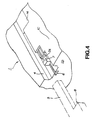
- Fig. 4 is an enlarged perspective view showing important portions of a loading surface section of the battery device shown in Fig. 1.
- Fig. 5 is a perspective view illustrating the loading of a battery device according to the present invention onto a main apparatus.
- Fig. 6 is a plan view showing an example of main apparatus constituting the loading device for the battery device of Figs. 1 to 4.
- Fig. 7 is a longitudinal cross-sectional view taken along line A-A of Fig. 6.
- Fig. 8 is a partial longitudinal cross-sectional view showing the state in which the battery device is loaded on the main apparatus of Fig. 6 constituting the loading device for the battery device.
- Fig. 9 is a schematic plan view from underneath illustrating loading using the battery device and the main apparatus constituting an embodiment of the loading device according to the invention for the battery device.
- Fig. 10 is a schematic front view illustrating loading using the loading device for the battery device of Fig. 9.
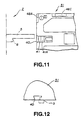
- Fig. 11 is a schematic front view illustrating loading of a conventional battery device on main apparatus constituting the loading device for the battery device according to the invention.
- Fig. 12 is a schematic front view illustrating loading of the conventional battery device on the main apparatus constituting the loading device for the battery device according to the invention.
- Fig. 13 is a plan view from underneath showing a conventional battery device.
- Fig. 14 is a plan view from above showing a main apparatus for loading a conventional battery device.
- Fig. 15 is a perspective view of a conventional battery device.
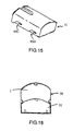
- Fig. 16 is a perspective view of a battery device and a recess of an electronic apparatus in accordance with the invention.
- Fig. 17 is a top perspective view of an electronic apparatus in accordance with the invention.
- the battery device 1 is basically the same in construction as the conventional battery device 51, and is comprised of a casing 1A having a battery housing unit 1B, a plurality of rechargeable cells 11 housed within the battery housing unit 1B and terminals 12A, 12B connected to the rechargeable cells 11.
- the casing 1A has a substantially rectangular loading surface 1C at the peripheral bottom surface defining a substantially square-shaped battery housing unit 1B, as shown in Fig. 3.
- the battery housing unit 1B is delimited by an inner wall section having an arcuate cross-section for defining a space within which to hold substantially columnar-shaped rechargeable cells side-by-side.
- two rows each comprised of two substantially columnar-shaped rechargeable cells are arranged side-by-side in two tiers.
- a discriminating recess 4 On the loading surface section 1C is formed a discriminating recess 4 having an opening end opened in an abutment surface 1D extending at right angles to the loading surface section 1C in registration with a thickened portion of the inner wall section of the battery housing unit 1B, as shown in Fig. 2.
- a mounting recess 6 is formed in the loading surface section 1C in parallel with the discriminating recess 4, as shown in Fig. 4.
- a charging discriminating member 7 is formed with a cut-out groove 7A opened in the loading surface section 1C.
- the cut-out recess 7A is engaged in use by an engagement member, not shown, provided on the main apparatus, so as to permit the battery device 1 to be dismounted and pulled out of the main apparatus.
- a substantially square-shaped groove 14 connecting to one end of the discrimination groove 4.
- a substantially rectangular-shaped loading guide recess 15 at a midportion of the loading surface section 1C in registration with the centerline of the groove 14.
- a substantially rectangular loading and holding recess 16 at a position substantially coincident with the centerline of the guide recess 15.
- first and second guide recesses 9A and 9B in series with each other so as to be opened at one ends at the loading surface section 1C.
- a third guide recess 9C and a fourth guide recess 9D in series with each other, as shown in Figs. 1 and 3, in registration with the first and second guide recesses 9A and 9B, respectively.
- the discrimination groove 4 since the discrimination groove 4 is offset to one side of the centerline of the loading surface section 1C, and the beginning ends of the first and third guide recesses 9A and 9C are positioned closer to the abutment surface 1D normal to the loading surface 1C than the terminal end of the discrimination groove 4, the discrimination groove 4 can be positively discriminated by the main apparatus at the initial loading stage in which the first to fourth guide grooves 9A to 9D of the battery device 1 are caused to bear against the main apparatus. Thus it becomes possible to positively prohibit mistaken loading of the battery device 1 on the main apparatus as well as to prohibit destruction of the main apparatus.
- the loading device 3 (See Fig. 9) for the battery device is constituted by the battery device 1 and the main apparatus 2 on which the battery device 1 is loaded.
- the battery device 1 is similar to that described above in reference to Figs. 1 to 4.
- the main apparatus 2 has a casing 2A having a setting surface section 2B on which the battery device 1 is loaded, and a main body of the apparatus has connection terminals 13A, 13B which are respectively abutted against and connected to the terminals 12A, 12B of the battery device 1 during use.
- the casing 2A is formed with a substantially L-shaped discrimination protrusion 5 having its one end secured to an abutment surface 2E extending at right angles to the setting surface section 2B, as shown in Figs. 6 and 7.
- the discrimination protrusion 5 has its proximal end formed integrally with an actuating portion 8.
- the setting surface section 2B has a substantially rectangular opening 20 from one lateral end of which is integrally protruded a substantially rectangular engagement portion 17.
- the engagement portion 17 is designed to be resiliently flexed about its proximal portion and has its distal end formed integrally with an engagement lug 17A.
- a loading guide 18 in the form of a pillar of an elliptical cross-section on a line of extension of the engagement portion 17.
- a substantially rectangular opening 21 having its centerline coincident with the loading guide 18.
- the loading holding portion 19 is designed to be resiliently flexed about its proximal end as a fulcrum point and has its distal end formed integrally with a loading and holding lug 19A.
- the casing 2A is integrally formed with a pair of guide wall sections 2C, 2D extending at right angles to the setting surface section 2B and parallel to the loading direction.
- On the inner wall surface of the guide wall section 2C are formed L-shaped first and second guide protrusions 10A and 10B in series with each other.
- a third guide protrusion 10C and a fourth guide protrusion 10D facing the first and second guide protrusions 10A and 10B, respectively.
- the setting surface section 2B has a discrimination protrusion 5 which is offset with respect to the centerline of the setting surface section 2B, and is longitudinally dimensioned so as to have a portion extending parallel to the first guide protrusion 10A and the second guide protrusion 10C.
- the beginning ends of the first and third guide protrusions 10A and 10C are positioned closer to the abutment surface 2E than the terminal end of the discrimination protrusion 5.
- first connection terminal 13A as a positive electrode
- second connection terminal 13B as a negative electrode
- the first connection terminal 13A and the second connection terminal 13B are connected to a dc conversion unit, not shown.
- the first and second connection terminals 13A and 13B are protected by a protection member 22 having a substantially U-shaped cross-section.
- the protection member 22 is mounted for movement along the loading direction and is moved towards the abutment surface 2E by elastic deformation of an elastic member, not shown, for enabling the first connection terminal 13A and the second connection terminal 13B to protrude out of the protection member 22.
- the operation of loading of the battery device 1 by the loading device 3 for the battery device, and of movement of the charging discrimination member 7 provided in the battery device 1, will now be explained.
- the first to fourth guide protrusions 10A to 10D formed on the inner wall sections of the guide wall sections 2C and 2D of the main apparatus 2 are caused to bear against the first to fourth guide recesses 9A to 9D formed on the lateral sides of the battery device 1 extending parallel to the loading direction, as shown in Fig. 8.
- the first to fourth guide protrusions 10A to 10D formed on the guide wall sections 2C and 2D of the main apparatus 2 are moved in the first to fourth guide recesses 9A to 9D of the battery device 1, respectively.
- the battery device 1 is retained by the main apparatus 2 by the guide protrusions being caused to bear against the ends of the first to fourth guide recesses 9A to 9D, respectively.
- the loading guide 18 integrally formed in the setting surface section 2B of the main apparatus 2 is inserted into the loading guide recess 15 formed in the loading surface section 1C, so that the loading guide 18 is moved along the loading guide recess 15.
- the battery device 1 is retained by the main apparatus 2 by the loading guide 18 being caused to bear against the one end of the loading guide recess 15.
- the loading and holding portion 19 protuberantly formed on the setting surface section 2B of the main apparatus 2 is resiliently flexed within the loading and holding recess 16 formed in the loading surface section 1C of the battery device 1, so that the loading and holding lug 19A is engaged in the loading and holding recess 16 for retaining the battery device 1 on the main apparatus 2.
- the actuating portion 8 formed on the discrimination protrusion 5 of the main apparatus 2 is caused to bear against one end of the charging discriminating member 7 movably mounted in the mounting recess 6 of the loading surface section 1.
- the charging discriminating member 7 is thrust inward by the actuating portion 8.
- the loading and holding portion 19 is elastically flexed by one end of the loading and holding recess 16 for disengaging the loading and holding lug 19A from the loading and holding recess 16.
- the engagement lug 17A protuberantly formed as one with the engagement portion 17 of the setting surface section 2B of the main apparatus 2 is engaged in the cut-out groove 7A formed in the charging discriminating member 7 movably mounted within the mounting recess 6 of the loading surface section 1C of the battery device.
- the charging discrimination member 7 is pulled out by the engagement lug 17A.
- the operation of discriminating the battery device 1 by the main apparatus 2 is explained by referring to Figs. 9 to 12.
- the discrimination protrusion 5 is inserted along the discrimination recess 4, as shown in Figs. 9 and 10.
- the main apparatus 2 discriminates the battery device 1 loaded thereon.
- the main apparatus discriminates the conventional battery device of Figs. 13-15 by the discrimination protrusion 5 being abutted against the loading surface section 51B of the battery device 51.
- the conventional battery device 51 is tilted by abutment of the discrimination protrusion 5 against the end surface section.
- the main apparatus recognizes the loading of an inappropriate battery device 51 based on the tilt of the battery device 51.
- Figs. 16 to 18 illustrate the operative relationship between a battery device 1 and electronic apparatus in accordance with the invention.
- Fig. 16 is a perspective view of a battery device 1 adapted to be inserted in a recess 30.
- a discrimination protrusion 5 is provided within the recess 30 in order to prevent insertion of an improper type of battery device.
- Fig. 17 is a top perspective view of an electronic apparatus in which such a recess 30 is provided.
- Fig. 18 shows a profile of a battery device 1 disposed in a recess 30, in comparison with a conventional battery device 51 (also shown in profile).
- the discrimination groove 4 is formed with an offset with respect to the centerline of the loading surface section 1C of the battery device 1, and the beginning ends of the first and second guide recesses 9A and 9C are located so as to be closer to the abutment surface 1D normal to the loading surface section 1C than the terminal end of the discrimination groove 4, while the discrimination protrusion 5 is formed at a position offset with respect to the centerline of the setting surface section 2B of the main apparatus 2, and the beginning ends of the first and third guide protrusions 10A and 10C are located so as to be closer to the abutment surface 2E than the terminal ends of the discrimination protrusion 5.
- the discrimination protrusion 5 is inserted into the discrimination recess 4 in the initial loading position in which the first to fourth guide protrusions 10A to 10D formed on the main apparatus 2 are abutted against the first to fourth guide recesses 9A to 9D formed in the battery device 1.
- the loading device 3 for the battery device to positively and clearly discriminate the conventional battery device 51 by the discrimination protrusion 5, before completion of the loading of the conventional battery device 51 on the main apparatus 2, thereby enabling rejection of loading of the conventional battery device 51.
- the discrimination groove is formed at a position offset relative to the centerline of the loading surface section, and the beginning end of the guide recess is located so as to be closer to the abutment surface than the terminal end of the discrimination groove, and hence the discrimination groove can be positively and clearly discriminated by the main apparatus in the initial loading state in which the guide recess in the battery device is abutted against the main apparatus. It therefore becomes possible to positively prevent mistaken loading and consequent destruction of the main apparatus.
- the discrimination groove is formed with an offset with respect to the centerline of the loading surface section of the battery device, and the beginning ends of the first and second guide recesses are located so as to be closer to the abutment surface normal to the loading surface section than the terminal ends of the discrimination groove, while the discrimination protrusion is formed at a position offset with respect to the centerline of the setting surface section of the main apparatus, and the beginning ends of the first and third guide protrusions are located so as to be closer to the abutment surface than the terminal ends of the discrimination protrusion.
Description
- This invention relates to a battery device having enclosed therein a rechargeable cell or a dry cell, and a loading device upon which the battery device is seated, such as a portable electronic apparatus which employs the battery device as a power source.
- A portable electronic apparatus, such as a portable video tape recorder, a tape player, a video camera or a disc player, is generally designed so that a dc power source, such as a rechargeable cell or a dry cell, may be used as a power source in addition to a commercial power source supplied via a dc conversion adapter.
- Consequently, in these electronic apparatus, a battery loading unit is built into a portion of a casing of the apparatus, and a battery device, having enclosed therein a rechargeable cell or a dry cell, is connected to the battery loading unit. When the charge of the cell in the battery device has become depleted, the battery device is loaded on a battery loading unit provided on a charger having a dc conversion adapter.
- A
conventional battery device 51 is explained with reference to Figs. 13 and 15. Thebattery device 51 is roughly made up of acasing 51A having a battery housing unit therein, a rechargeable cell (not shown), housed within the battery housing unit, and a pair ofterminals 48A, 48B connected to the rechargeable cell. - The
casing 51A has a substantially rectangular loading surface section 51B, and two substantially columnar-shaped chargeable cells that are housed within the battery housing unit. In the loading surface section 51B is formed a mounting recess 40 in parallel with the loading direction so as to be opened at its one end on an abutment surface extending at right angles to the loading surface section. - In the
mounting recess 40 is movably mounted a chargingdiscriminating member 41 which indicates the charging state. The chargingdiscriminating member 41 is moved along the mounting recess 40 for indicating, depending on the position to which the discriminating member has been moved, whether the rechargeable cell housed within the housing unit is charged or yet to be charged. - The loading surface section 51B has a substantially rectangular-
shaped recess 43 at a position coincident with the centerline of themounting recess 40. At a midposition of the surface section, substantially coincident with therecess 43, is formed a substantially rectangularloading guide recess 44. In addition, a substantially rectangular loading andholding recess 45 is disposed in such a way that its centerline is coincident with the loading guide recess 44. - The
casing 51A has substantially L-shaped first andsecond guide grooves casing 51A also has athird guide groove 46C and afourth guide groove 46D in a lateral surface thereof opposite to the lateral surface carrying the first and second guide grooves so that the third and fourth guide grooves face the first and second guide grooves, respectively as shown in Fig. 15. - Referring to Fig. 14, a
main apparatus 52 on which the above-described battery device is loaded is now explained. Themain apparatus 52 includes acasing 52A having a setting surface section 52B for loading thebattery device 51 thereon, andconnection terminals terminals 48A, 48B of thebattery device 51. - The
casing 52A has a substantiallyrectangular operating boss 58 having its one end integrally connected to an abutment surface 52E extending at right angles to the setting surface section 52B. The setting surface section 52B has a substantiallyrectangular opening 53 at a position coincident with the centerline of theoperating boss 58, and a substantiallyrectangular engagement portion 54 integrally formed to extend from a lateral surface of theopening 53. Theengagement portion 54 is resiliently flexible about its proximal point and has anengagement boss 54A at its distal end. - In the setting surface section 52B is integrally formed a
loading guide section 55 in the form of a substantially elliptical pillar. The setting surface section 52B has a substantiallyrectangular opening 56 at a position coincident with the centerline of theloading guide section 55 and a substantially rectangularloading holding section 57 is integrally protruded from a lateral side of theopening 56. Theloading holding section 57 is resiliently flexible about the proximal point, and has aloading holding protrusion 57A integrally formed at its distal end. - The
casing 52A has a pair ofguide wall sections guide wall section 52C are formed substantially L-shaped first andsecond guide protrusions - On the inner wall section of the guide wall section of the
casing 52A opposite to theguide wall section 52C having the first andsecond guide protrusions guide wall protrusion 47C and afourth guide protrusion 47D facing thefirst guide protrusion 47A and thesecond guide protrusion 47B, respectively. - On both lateral end portions of the abutment surface 52E extending at right angles to the setting surface section 52B are formed first and
second connection terminals connectable terminals - The first and
second connection terminals protection member 50 having a substantially U-shaped cross-section. Theprotection member 50 is mounted for movement in the loading direction. Theprotection member 50 has a resilient member (not shown) resiliently flexed so as to be moved towards the abutment surface 52E for enabling thefirst connection terminal 49A and thesecond connection terminal 49B to protrude out from theprotection member 50. - The operation of loading the
battery device 51 on themain apparatus 52 and the operation of the chargingdiscriminating member 41 provided on thebattery device 51 are now explained. First, the first tofourth guide protrusions 47A to 47D formed on the inner wall surfaces of theguide wall sections fourth guide grooves 46A to 46D formed in thebattery device 51. - As the
battery device 51 is moved along the loading direction, the first tofourth guide protrusions 47A to 47D protuberantly formed on theguide wall sections main apparatus 52 are moved along the first tofourth guide grooves 46A to 46D formed in thebattery device 51 until being abutted against the ends of the first tofourth guide grooves 46A to 46D. Thebattery device 51 is retained in this manner by themain apparatus 52. - When the
battery device 51 is moved along the loading direction, theloading guide section 55 formed on the setting surface section 52B of themain apparatus 52 is introduced into theloading guide recess 44 formed in the loading surface section 51B. Theloading guide section 55 is moved along theloading guide recess 44. Thebattery device 51 is retained by themain apparatus 52 by theloading guide section 55 being abutted against one end of theloading guide recess 44. - As the
battery device 51 is further moved along the loading direction, theloading holding section 57 protuberantly formed on theloading surface section 52A of themain apparatus 52 is resiliently flexed in the loadingholding guide recess 45 formed in theloading surface section 51A. Thebattery device 51 is retained in this manner by the loading and holdingprotrusion 57A being engaged in the loading and holdingrecess 45. - When the
battery device 51 is further moved along the loading direction of themain apparatus 52, the actuatingprotrusion 58 protuberantly formed on the setting surface section 52B ofmain apparatus 52 is caused to bear against the end of the chargingdiscriminating member 41 movably mounted in themounting recess 40 of the loading surface section 51B. Consequently, when thebattery device 51 is moved in this manner along the loading direction, the chargingdiscriminating member 41 is thrust by the actuatingprotrusion 58. As thebattery device 51 loaded on themain apparatus 52 is pulled out in a direction opposite to the loading direction, theloading holding section 57 is resiliently deflected by one end of theloading holding recess 45 for disengaging the loading and holdingprotrusion 57A from the loading and holdingrecess 45. - As the
battery device 51 provided on themain apparatus 52 is pulled out in a direction opposite to the loading direction, theengagement protrusion 58 formed integrally on the setting surface section 52B of the main apparatus is engaged in a cut-out groove 41A formed in the chargingdiscriminating member 41 movably mounted in themounting recess 40 of theloading surface section 51A. Consequently, as thebattery device 51 is moved in the direction opposite to the loading direction, thecharging discrimination member 41 is pulled out by theengagement protrusion 58. - The
battery device 51 is occasionally designed as a high capacity battery device having two stages of the battery devices in order to permit the electronic apparatus to be employed for a longer time interval. With such battery device, two rechargeable cells are housed in a side-by-side relation to each other. - Heretofore, the usual battery device and the high capacity battery device are designed to have a common structure as to, for example, the shape of the loading surface section for the electronic apparatus, so that the usual battery device or the high capacity battery device may be interchangeably loaded on the electronic apparatus.
- However, certain electronic apparatus cannot be used except with the high capacity battery device. The electronic apparatus having the high capacity battery device connected thereto can be used for a longer time. In addition, some of the electronic apparatus need to be used for prolonged time in order to be used conveniently. For example, some of the portable video cameras are designed so that the usual battery device cannot be connected thereto, in order to assure continuous photographing.
- That is, if the usual battery device is provided on the portable video camera for prolonged photographing, the video camera operation may cease thereby interrupting photographing, necessitating the burdensome requirement that the consumed battery device be charged and exchanged frequently. Consequently, with some of the electronic apparatus, it is necessary to discriminate the usual battery device and the high capacity battery device from each other to permit the battery device suitable to the operating conditions of the electronic apparatus to be powered with the battery device.
- Referring to Figs. 13 and 14, the loading device for discriminating the usual battery device from the high capacity battery device is now explained. The
usual battery device 51 in the present battery loading device has a discrimination recess 53 on its lateral surface parallel to the loading direction of the loading surface section, as shown in Fig. 13. On the other hand, themain apparatus 52 has anoperating member 54 on an inner wall surface of theguide wall section 52C, as shown in Fig. 14. - The present loading device utilizes a push-pull switch, that is, a switch which is turned on when the
operating member 54 is moved by a force and which is turned off when the force is removed. Such a push-pull switch is provided on the inner wall of one of theguide wall sections 52C of themain apparatus 52. - With such a battery loading device, when the
battery device 51 is inserted on the setting surface section 52B, theoperating member 54 provided on themain apparatus 52 is moved by the lateral surface of thebattery device 51. When moved to a position of thediscriminating recess 53 formed in thebattery device 51, theoperating member 54 is protruded so as to produce a detection sound or turn on a detection light for apprising the user that thebattery device 51 has been detected. - With the above-described slot-in type loading device for the battery device, in which a bottomed box-shaped loading section is provided in the main apparatus and the battery device is inserted via an aperture formed on one lateral side of the loading device until it is housed therein in its entirety, the
operating member 54 is repeatedly changed on and off in the course of loading of the battery device. Thus, the loading device for the battery device has a defect in that the circuit of theoperating member 54 may be adversely affected by such repeated and frequent changeover operations of theoperating member 54. This may result in an increased likelihood of a failure in detection. - On the other hand, the loading device for the battery device detects the type of the
battery device 51 loaded on themain apparatus 52 in a simple manner. It is not designed so that the main apparatus may prevent the loading of thebattery device 51. That is, the type of battery device is determined after thebattery device 51 has been fully loaded on themain apparatus 52. However, since the electronic apparatus needs to be protected against destruction, it is desirable to initially determine the type ofbattery device 51 when it is attempted to connect thebattery device 51 with themain apparatus 52. - In addition, with the above-described loading device, the space for mounting the operating
member 54 to detect thebattery device 51 must be on theguide wall section 52C of themain apparatus 52. However, this loading device is not desirable for a portable electronic apparatus which requires a reduced size and thickness. - Document EP-A-0 559 573 discloses a battery device comprising a guide groove and an inverted insertion inhibiting groove which are provided along the centerline of respective outer surfaces of the battery device.
- It is therefore an object of the present invention to provide a battery device with which it is possible to clearly and reliably determine the type of battery device in order to inhibit the mistaken loading of an incorrect battery type on the main apparatus, thereby preventing damage to the main apparatus. It is another object of the present invention to provide a loading device for a battery device which similarly provides a clear and reliable determination of a battery type in order to inhibit the mistaken loading of an incorrect battery on the main apparatus in order to prevent damage to the main apparatus.
- For accomplishing the above objects, the battery device according to the present invention comprises: a casing having a battery housing unit disposed therein and having a loading surface section on a lateral outer surface thereof, said loading surface section being adapted for connection to a setting surface section of a main apparatus, and said battery housing unit in said housing being adapted for receiving at least one battery, wherein said loading surface section of the casing has a discrimination groove having an opening end opened in an abutment surface and extending from said opening end in a direction parallel to the loading direction of the battery device on the main apparatus, said abutment surface being formed on the loading surface of the casing in a direction at right angles to the loading surface section, and wherein at least a pair of guide recesses are formed in lateral surface sections of the casing extending at right angles to the loading surface section, parallel to the loading direction, at an outer periphery of the casing, said discrimination groove being located at a position offset relative to the centerline of the loading surface section and the front end of the guide recesses, with respect to the loading direction of the battery device on the main apparatus, being closer to said abutment surface than the rear end of the discrimination groove.
- The battery housing unit may be formed by a spacing delimited by a continuous inner wall section having an arcuate cross-section for holding plural batteries each of a substantially columnar cross-section in a side-by-side relation. The discrimination groove is preferably formed in the loading surface section in registration with a thickened portion of the inner wall section.
- The casing preferably has terminals at the ends of the lateral surface provided with the opening end of the discrimination groove. The terminals are for connection to the battery housed within the battery housing unit.
- The mounting recesses may be disposed parallel to each other. A charging discrimination member may be movably mounted facing the mounting recesses for indicating that the battery is in a non-charged state or in a charged state.
- For accomplishing the above-mentioned objects, a loading device for a battery device according to the present invention comprises: a casing having a battery housing unit therein and having a loading surface section on an outer surface thereof, said loading surface section being connectable to a setting surface section of a main apparatus, and said battery housing unit being adapted for housing at least one battery, wherein said loading surface section of the casing has a discrimination groove having an opening end opened in an abutment surface and extending from said opening end parallel to the loading direction of the battery device on the main apparatus, said abutment surface being formed on the loading surface of the casing in a direction at right angles to the loading surface section, and a main apparatus having a casing having in turn a setting surface section on a lateral outer surface thereof for loading the battery device thereon, said casing also having a rib-shaped discrimination protrusion secured at one end thereof to an abutment surface formed on the setting surface section at right angles thereto, said discrimination protrusion being formed integrally with the setting surface section, said discrimination protrusion on the main apparatus being detachably engagable in said discrimination groove in the battery device, wherein the battery device has at least a pair of guide recesses on its lateral surfaces extending at right angles to the loading surface section extending parallel to the loading direction, the discrimination groove being offset with respect to the centerline of the loading surface section, and the front end of the guide recesses, with respect to the loading direction of the battery device on the main apparatus, being closer to the abutment surface than the rear end of the discrimination groove, wherein the main apparatus has at least one guide wall section on each lateral side of the setting surface section for extending at right angles to the setting surface section, guide protrusions being formed on the inner wall section of the guide wall sections, the discrimination protrusion being integrally formed at an offset position with respect to the centerline of the setting surface section, with the front end of the guide protrusions, with respect to the loading direction of the battery device on the main apparatus, being closer to the abutment surface than the rear end of the discrimination protrusion, and wherein in the initial loading state in which the guide protrusions provided on the main apparatus are inserted into the guide recesses formed in the battery device, the discrimination protrusion is inserted into the discrimination groove during loading the battery device in the main apparatus.
- In the preferred embodiment of loading device according to the invention, the battery device has a discrimination groove and a mounting recess parallel to each other, and a charging discrimination member movably mounted facing the mounting recess for indicating whether the battery is in the charged state or in the non-charged state. The main apparatus has an actuating portion at the proximal end of the discrimination protrusion for inwardly thrusting the charging discrimination member provided on the battery device. The charging discrimination member has a cut-out groove facing the setting surface section of the main apparatus. The main apparatus includes an engagement protrusion engaged in the cut-out groove formed in the charging discrimination member in alignment with the actuating portion.
- With the above-described battery device according to the preferred embodiment of the present invention, since the discrimination groove is formed at a position offset with respect to the centerline of the loading surface section, and the beginning end of the guide groove is located closer to the abutment surface than the terminal end of the discrimination groove, it becomes possible for the main apparatus to detect the discrimination groove at the initial loading position when the guide recess of the battery device is abutted against the main apparatus.
- With the loading device for the battery device according to the preferred embodiment of the present invention, since the discrimination groove is offset with respect to the centerline of the loading surface section of the battery device, and the beginning end of the guide groove is closer to the abutment surface than the terminal end of the discrimination groove, while the discrimination protrusion is offset with respect to the centerline of the setting surface section of the main apparatus, and the beginning end of the guide protrusion is closer to the abutment surface than the terminal end of the discrimination protrusion, the discrimination protrusion is inserted into the discrimination groove in the initial loading state in which the guide protrusion formed on the main apparatus is abutted against the guide groove formed in the battery device.
- Consequently, with the present loading device for the battery device, if an inappropriate battery device is loaded on the main apparatus, the battery becomes tilted by the discrimination protrusion of the main apparatus being caused to bear against the setting surface section of the battery device before completion of loading of the battery device. Thus, it is possible with the loading device to reject attempted loading of an inappropriate battery device on the main apparatus.
- Fig. 1 is a plan view from underneath showing the loading surface section of a battery device according to an embodiment of the present invention.
- Fig. 2 is a front view showing the battery device shown in Fig. 1.
- Fig. 3 is a side view showing the battery device shown in Fig. 1.
- Fig. 4 is an enlarged perspective view showing important portions of a loading surface section of the battery device shown in Fig. 1.
- Fig. 5 is a perspective view illustrating the loading of a battery device according to the present invention onto a main apparatus.
- Fig. 6 is a plan view showing an example of main apparatus constituting the loading device for the battery device of Figs. 1 to 4.
- Fig. 7 is a longitudinal cross-sectional view taken along line A-A of Fig. 6.
- Fig. 8 is a partial longitudinal cross-sectional view showing the state in which the battery device is loaded on the main apparatus of Fig. 6 constituting the loading device for the battery device.
- Fig. 9 is a schematic plan view from underneath illustrating loading using the battery device and the main apparatus constituting an embodiment of the loading device according to the invention for the battery device.
- Fig. 10 is a schematic front view illustrating loading using the loading device for the battery device of Fig. 9.
- Fig. 11 is a schematic front view illustrating loading of a conventional battery device on main apparatus constituting the loading device for the battery device according to the invention.
- Fig. 12 is a schematic front view illustrating loading of the conventional battery device on the main apparatus constituting the loading device for the battery device according to the invention.
- Fig. 13 is a plan view from underneath showing a conventional battery device.
- Fig. 14 is a plan view from above showing a main apparatus for loading a conventional battery device.
- Fig. 15 is a perspective view of a conventional battery device.
- Fig. 16 is a perspective view of a battery device and a recess of an electronic apparatus in accordance with the invention.
- Fig. 17 is a top perspective view of an electronic apparatus in accordance with the invention.
- Fig. 18 is a plan view of a recess of an electronic apparatus, and a battery device according to the invention and a conventional battery device.
- Referring to Figs. 1 to 12, and 16 to 18, preferred embodiments of the present invention will be explained in detail. The
battery device 1 is basically the same in construction as theconventional battery device 51, and is comprised of a casing 1A having a battery housing unit 1B, a plurality of rechargeable cells 11 housed within the battery housing unit 1B andterminals - The casing 1A has a substantially rectangular loading surface 1C at the peripheral bottom surface defining a substantially square-shaped battery housing unit 1B, as shown in Fig. 3. The battery housing unit 1B is delimited by an inner wall section having an arcuate cross-section for defining a space within which to hold substantially columnar-shaped rechargeable cells side-by-side. Within the battery housing unit 1B, two rows each comprised of two substantially columnar-shaped rechargeable cells are arranged side-by-side in two tiers.
- On the loading surface section 1C is formed a
discriminating recess 4 having an opening end opened in anabutment surface 1D extending at right angles to the loading surface section 1C in registration with a thickened portion of the inner wall section of the battery housing unit 1B, as shown in Fig. 2. - A mounting
recess 6 is formed in the loading surface section 1C in parallel with thediscriminating recess 4, as shown in Fig. 4. In this mountingrecess 6 is movably mounted acharging discriminating member 7. Thecharging discriminating member 7 is formed with a cut-outgroove 7A opened in the loading surface section 1C. The cut-out recess 7A is engaged in use by an engagement member, not shown, provided on the main apparatus, so as to permit thebattery device 1 to be dismounted and pulled out of the main apparatus. - In the loading surface section 1C is formed a substantially square-shaped
groove 14 connecting to one end of thediscrimination groove 4. In the loading surface section 1C is formed a substantially rectangular-shapedloading guide recess 15 at a midportion of the loading surface section 1C in registration with the centerline of thegroove 14. In the loading surface section 1C is also formed a substantially rectangular loading and holdingrecess 16 at a position substantially coincident with the centerline of theguide recess 15. - In a lateral side of the casing 1A extending at right angles to the loading surface 1C parallel to the loading direction are formed substantially L-shaped first and second guide recesses 9A and 9B in series with each other so as to be opened at one ends at the loading surface section 1C. In the opposite lateral side of the casing 1A are formed a
third guide recess 9C and afourth guide recess 9D in series with each other, as shown in Figs. 1 and 3, in registration with the first and second guide recesses 9A and 9B, respectively. - The
discrimination groove 4 formed in the loading surface section 1C is offset with respect to the centerline of the loading surface section 1C, and is longitudinally dimensioned so as to have a portion extending parallel to thefirst guide recess 9A and thesecond guide recess 9C. In other words, the beginning ends of the first and third guide recesses 9A and 9C are positioned closer to theabutment surface 1D extending normal to the loading surface 1C than the terminal end of thediscrimination groove 4. - With the above-described
battery device 1 of the embodiment illustrated, since thediscrimination groove 4 is offset to one side of the centerline of the loading surface section 1C, and the beginning ends of the first and third guide recesses 9A and 9C are positioned closer to theabutment surface 1D normal to the loading surface 1C than the terminal end of thediscrimination groove 4, thediscrimination groove 4 can be positively discriminated by the main apparatus at the initial loading stage in which the first tofourth guide grooves 9A to 9D of thebattery device 1 are caused to bear against the main apparatus. Thus it becomes possible to positively prohibit mistaken loading of thebattery device 1 on the main apparatus as well as to prohibit destruction of the main apparatus. - Referring to Figs. 5 to 12, 15 and 16, an illustrative embodiment of the loading device for the battery device according to the present invention is explained. The loading device 3 (See Fig. 9) for the battery device is constituted by the
battery device 1 and themain apparatus 2 on which thebattery device 1 is loaded. Thebattery device 1 is similar to that described above in reference to Figs. 1 to 4. - The
main apparatus 2 has acasing 2A having a settingsurface section 2B on which thebattery device 1 is loaded, and a main body of the apparatus has connection terminals 13A, 13B which are respectively abutted against and connected to theterminals battery device 1 during use. - The
casing 2A is formed with a substantially L-shapeddiscrimination protrusion 5 having its one end secured to anabutment surface 2E extending at right angles to thesetting surface section 2B, as shown in Figs. 6 and 7. Thediscrimination protrusion 5 has its proximal end formed integrally with anactuating portion 8. - The setting
surface section 2B has a substantiallyrectangular opening 20 from one lateral end of which is integrally protruded a substantiallyrectangular engagement portion 17. Theengagement portion 17 is designed to be resiliently flexed about its proximal portion and has its distal end formed integrally with anengagement lug 17A. - On the
setting surface section 2B is protruded aloading guide 18 in the form of a pillar of an elliptical cross-section on a line of extension of theengagement portion 17. In thesetting surface section 2B is formed a substantiallyrectangular opening 21 having its centerline coincident with theloading guide 18. From a lateral side of theopening 21 is integrally protruded a substantially rectangularloading holding portion 19. Theloading holding portion 19 is designed to be resiliently flexed about its proximal end as a fulcrum point and has its distal end formed integrally with a loading and holdinglug 19A. - The
casing 2A is integrally formed with a pair ofguide wall sections setting surface section 2B and parallel to the loading direction. On the inner wall surface of theguide wall section 2C are formed L-shaped first andsecond guide protrusions 10A and 10B in series with each other. - On the inner wall surface of the opposite
guide wall section 2D to theinner wall section 2C carrying the first andsecond guide protrusions 10A, 10B are integrally formed athird guide protrusion 10C and a fourth guide protrusion 10D facing the first andsecond guide protrusions 10A and 10B, respectively. - The setting
surface section 2B has adiscrimination protrusion 5 which is offset with respect to the centerline of the settingsurface section 2B, and is longitudinally dimensioned so as to have a portion extending parallel to thefirst guide protrusion 10A and thesecond guide protrusion 10C. In other words, the beginning ends of the first andthird guide protrusions abutment surface 2E than the terminal end of thediscrimination protrusion 5. - At the ends of the
abutment surface 2E of thecasing 2A are formed, respectively, a first connection terminal 13A as a positive electrode and a second connection terminal 13B as a negative electrode. The first connection terminal 13A and the second connection terminal 13B are connected to a dc conversion unit, not shown. - The first and second connection terminals 13A and 13B are protected by a
protection member 22 having a substantially U-shaped cross-section. Theprotection member 22 is mounted for movement along the loading direction and is moved towards theabutment surface 2E by elastic deformation of an elastic member, not shown, for enabling the first connection terminal 13A and the second connection terminal 13B to protrude out of theprotection member 22. - The operation of loading of the
battery device 1 by theloading device 3 for the battery device, and of movement of the chargingdiscrimination member 7 provided in thebattery device 1, will now be explained. The first tofourth guide protrusions 10A to 10D formed on the inner wall sections of theguide wall sections main apparatus 2 are caused to bear against the first to fourth guide recesses 9A to 9D formed on the lateral sides of thebattery device 1 extending parallel to the loading direction, as shown in Fig. 8. - As the
battery device 1 is moved along the loading direction as indicated by an arrow in Fig. 8, the first tofourth guide protrusions 10A to 10D formed on theguide wall sections main apparatus 2 are moved in the first to fourth guide recesses 9A to 9D of thebattery device 1, respectively. Thebattery device 1 is retained by themain apparatus 2 by the guide protrusions being caused to bear against the ends of the first to fourth guide recesses 9A to 9D, respectively. - As the
battery device 1 is moved along the loading direction, theloading guide 18 integrally formed in thesetting surface section 2B of themain apparatus 2 is inserted into theloading guide recess 15 formed in the loading surface section 1C, so that theloading guide 18 is moved along theloading guide recess 15. Thebattery device 1 is retained by themain apparatus 2 by theloading guide 18 being caused to bear against the one end of theloading guide recess 15. - In addition, when the
battery device 1 is moved along the loading direction, the loading and holdingportion 19 protuberantly formed on thesetting surface section 2B of themain apparatus 2 is resiliently flexed within the loading and holdingrecess 16 formed in the loading surface section 1C of thebattery device 1, so that the loading and holdinglug 19A is engaged in the loading and holdingrecess 16 for retaining thebattery device 1 on themain apparatus 2. - Also, when the
battery device 1 is moved along the loading direction, the actuatingportion 8 formed on thediscrimination protrusion 5 of themain apparatus 2 is caused to bear against one end of thecharging discriminating member 7 movably mounted in the mountingrecess 6 of theloading surface section 1. Thus, when thebattery device 1 is moved along the loading direction, thecharging discriminating member 7 is thrust inward by the actuatingportion 8. - When the
battery device 1, thus loaded in position on themain apparatus 2, is pulled in an opposite direction to the loading direction, the loading and holdingportion 19 is elastically flexed by one end of the loading and holdingrecess 16 for disengaging the loading and holdinglug 19A from the loading and holdingrecess 16. - Also, when the
battery device 1, thus loaded in position on themain apparatus 2, is pulled in a direction opposite to the loading direction, theengagement lug 17A protuberantly formed as one with theengagement portion 17 of the settingsurface section 2B of themain apparatus 2 is engaged in the cut-outgroove 7A formed in thecharging discriminating member 7 movably mounted within the mountingrecess 6 of the loading surface section 1C of the battery device. Thus, when thebattery device 1 is pulled in an opposite direction to the loading direction, the chargingdiscrimination member 7 is pulled out by theengagement lug 17A. - The operation of discriminating the
battery device 1 by themain apparatus 2 is explained by referring to Figs. 9 to 12. When thebattery device 1 is loaded on themain apparatus 2, thediscrimination protrusion 5 is inserted along thediscrimination recess 4, as shown in Figs. 9 and 10. By the insertion of thediscrimination protrusion 5 into thediscrimination groove 4, themain apparatus 2 discriminates thebattery device 1 loaded thereon. - Since the
discrimination protrusion 5 is formed on themain apparatus 2 at a position offset with respect to the centerline of the mountingrecess 40 of thebattery device 1, as shown in Figs. 11 and 12, the main apparatus discriminates the conventional battery device of Figs. 13-15 by thediscrimination protrusion 5 being abutted against the loading surface section 51B of thebattery device 51. - In the initial loading stage in which the first and
fourth guide protrusions 10A and 10D of themain apparatus 2 are caused to bear against the first andfourth guide grooves conventional battery device 51 is tilted by abutment of thediscrimination protrusion 5 against the end surface section. Thus, the main apparatus recognizes the loading of aninappropriate battery device 51 based on the tilt of thebattery device 51. - Figs. 16 to 18 illustrate the operative relationship between a
battery device 1 and electronic apparatus in accordance with the invention. In particular, Fig. 16 is a perspective view of abattery device 1 adapted to be inserted in arecess 30. As shown, adiscrimination protrusion 5 is provided within therecess 30 in order to prevent insertion of an improper type of battery device. Fig. 17 is a top perspective view of an electronic apparatus in which such arecess 30 is provided. Fig. 18 shows a profile of abattery device 1 disposed in arecess 30, in comparison with a conventional battery device 51 (also shown in profile). - With the above-described
loading device 3 for the battery device of the embodiment illustrated, thediscrimination groove 4 is formed with an offset with respect to the centerline of the loading surface section 1C of thebattery device 1, and the beginning ends of the first and second guide recesses 9A and 9C are located so as to be closer to theabutment surface 1D normal to the loading surface section 1C than the terminal end of thediscrimination groove 4, while thediscrimination protrusion 5 is formed at a position offset with respect to the centerline of the settingsurface section 2B of themain apparatus 2, and the beginning ends of the first andthird guide protrusions abutment surface 2E than the terminal ends of thediscrimination protrusion 5. - Thus, with this
loading device 3 for the battery device, thediscrimination protrusion 5 is inserted into thediscrimination recess 4 in the initial loading position in which the first tofourth guide protrusions 10A to 10D formed on themain apparatus 2 are abutted against the first to fourth guide recesses 9A to 9D formed in thebattery device 1. - Thus it is possible with the
loading device 3 for the battery device to positively and clearly discriminate theconventional battery device 51 by thediscrimination protrusion 5, before completion of the loading of theconventional battery device 51 on themain apparatus 2, thereby enabling rejection of loading of theconventional battery device 51. - In the above-described example of a loading device for the battery device according to the present invention, the main apparatus on which the battery device is loaded is a charger for electrically charging the battery device. However, the main apparatus may also be constituted in the casing of an electronic apparatus, such as a portable video camera device, instead of being the charger.
- With the above-described preferred embodiment of the battery device according to the present invention, since the discrimination groove is formed at a position offset relative to the centerline of the loading surface section, and the beginning end of the guide recess is located so as to be closer to the abutment surface than the terminal end of the discrimination groove, and hence the discrimination groove can be positively and clearly discriminated by the main apparatus in the initial loading state in which the guide recess in the battery device is abutted against the main apparatus. It therefore becomes possible to positively prevent mistaken loading and consequent destruction of the main apparatus.
- In addition, with the above-described preferred embodiment of loading device for the battery device according to the present invention, the discrimination groove is formed with an offset with respect to the centerline of the loading surface section of the battery device, and the beginning ends of the first and second guide recesses are located so as to be closer to the abutment surface normal to the loading surface section than the terminal ends of the discrimination groove, while the discrimination protrusion is formed at a position offset with respect to the centerline of the setting surface section of the main apparatus, and the beginning ends of the first and third guide protrusions are located so as to be closer to the abutment surface than the terminal ends of the discrimination protrusion. Thus, the battery device can be discriminated clearly and positively by the discrimination protrusion in the initial loading state of the battery device on the main apparatus. Thus, it becomes possible to prohibit loading of the inappropriate battery device and consequent destruction of the main apparatus.
Claims (7)
- A battery device comprising :wherein said loading surface section (1C) of the casing has a discrimination groove (4) having an opening end opened in an abutment surface (1 D) and extending from said opening end in a direction parallel to the loading direction of the battery device on the main apparatus, said abutment surface (1D) being formed on the loading surface of the casing in a direction at right angles to the loading surface section (1C), anda casing (1A) having a battery housing unit (1B) disposed therein and having a loading surface section (1C) on a lateral outer surface thereof, said loading surface section (1C) being adapted for connection to a setting surface section of a main apparatus, and said battery housing unit in said housing being adapted for receiving at least one battery,
wherein at least a pair of guide recesses (9A - 9D) are formed in lateral surface sections of the casing extending at right angles to the loading surface section (1C), parallel to the loading direction, at an outer periphery of the casing,
said discrimination groove (4) being located at a position offset relative to the centerline of the loading surface section (1C) and the front end of the guide recesses (9A, 9C), with respect to the loading direction of the battery device on the main apparatus, being closer to said abutment surface (1D) than the rear end of the discrimination groove. - The battery device as claimed in claim 1, wherein the battery housing unit (1B) is formed by a spacing delimited by a continuous inner wall section having an arcuate cross-section for holding plural batteries, each having a substantially columnar cross-section, and said discrimination groove (4) is formed in the loading surface section (1C) in a thickened portion of the inner wall section.
- The battery device as claimed in claim 1 or 2, wherein the guide recesses (9A - 9D) comprise mounting recesses parallel to each other and a charging discrimination member (7) is movably mounted facing the mounting recess for indicating that the battery is non-charged or charged.
- The battery device as claimed in any one of claims 1 to 3, wherein the casing (1A) has terminals (12A, 12B) at the respective ends of the lateral surface (1D) provided with the opening end of the discrimination groove (4), said terminals being connected to the battery housed within the battery housing unit.
- A loading device comprising :wherein the battery device (1) has at least a pair of guide recesses (9A - 9D) on its lateral surfaces extending at right angles to the loading surface section (1C) extending parallel to the loading direction, the discrimination groove (4) being offset with respect to the centerline of the loading surface section (1C), and the front end of the guide recesses (9A, 9C), with respect to the loading direction of the battery device on the main apparatus, being closer to the abutment surface (1D) than the rear end of the discrimination groove (4),a battery device (1) comprising a casing (1A) having a battery housing unit (1B) therein and having a loading surface section (1C) on an outer surface thereof, said loading surface section (1C) being connectable to a setting surface section (2B) of a main apparatus (2), and said battery housing unit being adapted for housing at least one battery, wherein said loading surface section (1C) of the casing has a discrimination groove (4) having an opening end opened in an abutment surface (1D) and extending from said opening end parallel to the loading direction of the battery device (1) on the main apparatus (2), said abutment surface (1D) being formed on the loading surface of the casing in a direction at right angles to the loading surface section (1C), anda main apparatus (2) having a casing having in turn a setting surface section (2B) on a lateral outer surface thereof for loading the battery device (1) thereon, said casing also having a rib-shaped discrimination protrusion (5) secured at one end thereof to an abutment surface (2E) formed on the setting surface section (2B) at right angles thereto, said discrimination protrusion (5) being formed integrally with the setting surface section (2B),said discrimination protrusion (5) on the main apparatus being detachably engagable in said discrimination groove (4) in the battery device,
wherein the main apparatus (2) has at least one guide wall section (2C, 2D) on each lateral side of the setting surface section (2B) for extending at right angles to the setting surface section, guide protrusions (10A - 10D) being formed on the inner wall section of the guide wall sections (2C, 2D), the discrimination protrusion (5) being integrally formed at an offset position with respect to the centerline of the setting surface section (2B), with the front end of the guide protrusions (10A, 10C), with respect to the loading direction of the battery device on the main apparatus, being closer to the abutment surface (2E) than the rear end of the discrimination protrusion (5), and wherein
in the initial loading state in which the guide protrusions (10A, 10C) provided on the main apparatus (2) are inserted into the guide recesses (9A, 9C) formed in the battery device (1), the discrimination protrusion (5) is inserted into the discrimination groove (4) during loading the battery device in the main apparatus. - The loading device as claimed in claim 5, wherein
the battery device (1) has a discrimination groove (4) and a mounting recess (9A - 9D) parallel to each other, and a charging discrimination member (7) movably mounted facing the mounting recess for indicating whether the battery is charged or non-charged, and wherein
the main apparatus (2) has an actuating portion (8) at the proximal end of the discrimination protrusion (5) for moving inwardly the charging discrimination member (7) provided on the battery device (1). - The loading device as claimed in claim 6, wherein the charging discrimination member (7) has a cut-out groove (7A) facing the setting surface section (2B) of the main apparatus (2), the main apparatus including an engagement protrusion engagable in the cut-out groove (7A) formed in the charging discrimination member in alignment with the actuating portion, and wherein the engagement protrusion is engaged in the cut-out groove (7A) when the loading surface section (1C) of the battery device (1) is detached from the setting surface section (2B) of the main apparatus (2) for extracting and shifting the charging discrimination member (7).
Priority Applications (1)
| Application Number | Priority Date | Filing Date | Title |
|---|---|---|---|
| DE29521896U DE29521896U1 (en) | 1994-09-02 | 1995-09-01 | Battery device and charger for a battery device |
Applications Claiming Priority (3)
| Application Number | Priority Date | Filing Date | Title |
|---|---|---|---|
| JP21021194 | 1994-09-02 | ||
| JP21021194A JP3627260B2 (en) | 1994-09-02 | 1994-09-02 | Battery device and apparatus for mounting the battery device |
| JP210211/94 | 1994-09-02 |
Publications (2)
| Publication Number | Publication Date |
|---|---|
| EP0707350A1 EP0707350A1 (en) | 1996-04-17 |
| EP0707350B1 true EP0707350B1 (en) | 2002-06-05 |
Family
ID=16585635
Family Applications (1)
| Application Number | Title | Priority Date | Filing Date |
|---|---|---|---|
| EP95401991A Expired - Lifetime EP0707350B1 (en) | 1994-09-02 | 1995-09-01 | Battery device and loading device for battery device |
Country Status (8)
| Country | Link |
|---|---|
| US (1) | US5672441A (en) |
| EP (1) | EP0707350B1 (en) |
| JP (1) | JP3627260B2 (en) |
| KR (1) | KR100415243B1 (en) |
| CN (3) | CN1090386C (en) |
| ES (1) | ES2179863T3 (en) |
| HK (3) | HK1013174A1 (en) |
| MY (1) | MY114894A (en) |
Cited By (1)
| Publication number | Priority date | Publication date | Assignee | Title |
|---|---|---|---|---|
| US7485394B2 (en) | 2003-12-26 | 2009-02-03 | Sony Corporation | Battery having a case with an identification recess and guide grooves for coupling to an electronic device |
Families Citing this family (32)
| Publication number | Priority date | Publication date | Assignee | Title |
|---|---|---|---|---|
| JP3575646B2 (en) * | 1995-12-06 | 2004-10-13 | ソニー株式会社 | Battery Pack |
| JPH11274758A (en) * | 1998-03-19 | 1999-10-08 | Smk Corp | Retaining device for small-size electronic equipment |
| JP3667982B2 (en) * | 1998-03-19 | 2005-07-06 | Smk株式会社 | Device for attaching and detaching small electronic devices |
| USD432982S (en) * | 1999-02-01 | 2000-10-31 | Sony Corporation | Rechargeable battery |
| JP4110656B2 (en) * | 1999-02-17 | 2008-07-02 | ソニー株式会社 | Battery pack, battery mounting device, power supply device, and electronic device |
| US6075341A (en) * | 1999-02-17 | 2000-06-13 | Black & Decker Inc. | Power pack charging system for a power tool |
| JP4110657B2 (en) | 1999-02-17 | 2008-07-02 | ソニー株式会社 | Battery pack, battery mounting device, power supply device, and electronic device |
| USD426513S (en) * | 1999-03-12 | 2000-06-13 | Eveready Battery Company, Inc. | Battery pack casing |
| US6326767B1 (en) | 1999-03-30 | 2001-12-04 | Shoot The Moon Products Ii, Llc | Rechargeable battery pack charging system with redundant safety systems |
| USD428384S (en) * | 1999-08-23 | 2000-07-18 | Sony Corporation | Rechargeable battery |
| EP1128517A3 (en) * | 2000-02-24 | 2003-12-10 | Makita Corporation | Adapters for rechargeable battery packs |
| US6326766B1 (en) * | 2000-06-09 | 2001-12-04 | Shoot The Moon Products Ii, Llc | Rechargable battery pack and battery pack charger with safety mechanisms |
| US6525511B2 (en) | 2000-08-11 | 2003-02-25 | Milwaukee Electric Tool Corporation | Adapter for a power tool battery |
| KR100919332B1 (en) * | 2001-07-24 | 2009-09-25 | 소니 가부시끼 가이샤 | Battery device |
| CN1812160B (en) | 2001-07-25 | 2015-05-27 | 索尼公司 | Battery device used for loading on electronic equipment |
| US6729413B2 (en) | 2001-08-24 | 2004-05-04 | Black & Decker Inc. | Power tool with battery pack ejector |
| US7835534B2 (en) | 2003-10-14 | 2010-11-16 | Robert Bosch Gmbh | Battery charging jobsite lunchbox |
| US8604752B2 (en) | 2003-10-14 | 2013-12-10 | Robert Bosch Gmbh | Portable battery charging and audio unit |
| JP2005165545A (en) | 2003-12-01 | 2005-06-23 | Sony Corp | Electronic equipment and battery pack |
| JP4123517B2 (en) * | 2003-12-26 | 2008-07-23 | ソニー株式会社 | Battery device |
| JP4123515B2 (en) * | 2003-12-26 | 2008-07-23 | ソニー株式会社 | Battery device |
| US20060251958A1 (en) * | 2005-05-05 | 2006-11-09 | Adan Ayala | Battery charge indicator |
| JP4458024B2 (en) * | 2005-11-17 | 2010-04-28 | パナソニック電工株式会社 | Electric tool |
| JP4600415B2 (en) * | 2007-03-30 | 2010-12-15 | ソニー株式会社 | Battery pack |
| JP5391525B2 (en) * | 2007-03-30 | 2014-01-15 | ソニー株式会社 | Battery pack |
| JP6434656B2 (en) * | 2015-10-10 | 2018-12-05 | 華為技術有限公司Huawei Technologies Co.,Ltd. | Electronic equipment |
| JP6191796B1 (en) | 2017-02-10 | 2017-09-06 | ソニー株式会社 | Battery and connected equipment |
| JP6961985B2 (en) * | 2017-02-10 | 2021-11-05 | ソニーグループ株式会社 | Battery and connected devices |
| EP4016718A1 (en) * | 2017-02-10 | 2022-06-22 | Sony Group Corporation | Battery and connection apparatus |
| JP6191795B1 (en) | 2017-02-10 | 2017-09-06 | ソニー株式会社 | Battery and connected equipment |
| US10615384B2 (en) | 2017-02-10 | 2020-04-07 | Sony Corporation | Battery and connection apparatus |
| JP6555305B2 (en) * | 2017-08-08 | 2019-08-07 | ソニー株式会社 | Battery and connected equipment |
Family Cites Families (5)
| Publication number | Priority date | Publication date | Assignee | Title |
|---|---|---|---|---|
| GB8820230D0 (en) * | 1988-08-25 | 1988-09-28 | Steeper Hugh Ltd | Battery & battery receptacle arrangement |
| JP3263855B2 (en) * | 1992-03-06 | 2002-03-11 | ソニー株式会社 | battery pack |
| CA2408978C (en) * | 1992-05-29 | 2004-12-28 | Sony Corporation | Battery cartridge having hollow electrodes and a recess for detecting misuse and/or recessed terminals |
| JP3289320B2 (en) * | 1992-06-30 | 2002-06-04 | ソニー株式会社 | battery pack |
| JP3215231B2 (en) * | 1993-07-26 | 2001-10-02 | 株式会社東芝 | Portable information processing device |
-
1994
- 1994-09-02 JP JP21021194A patent/JP3627260B2/en not_active Expired - Lifetime
-
1995
- 1995-08-31 US US08/521,758 patent/US5672441A/en not_active Expired - Lifetime
- 1995-09-01 ES ES95401991T patent/ES2179863T3/en not_active Expired - Lifetime
- 1995-09-01 EP EP95401991A patent/EP0707350B1/en not_active Expired - Lifetime
- 1995-09-02 CN CN95117112A patent/CN1090386C/en not_active Expired - Lifetime
- 1995-09-02 MY MYPI95002607A patent/MY114894A/en unknown
- 1995-09-02 CN CNB200410069939XA patent/CN1276526C/en not_active Expired - Lifetime
- 1995-09-02 CN CNB991069552A patent/CN1169243C/en not_active Expired - Lifetime
- 1995-09-02 KR KR1019950028683A patent/KR100415243B1/en not_active IP Right Cessation
-
1998
- 1998-12-17 HK HK98113954A patent/HK1013174A1/en not_active IP Right Cessation
-
2000
- 2000-06-01 HK HK00103342A patent/HK1025671A1/en not_active IP Right Cessation
-
2005
- 2005-05-26 HK HK05104430A patent/HK1073533A1/en not_active IP Right Cessation
Cited By (1)
| Publication number | Priority date | Publication date | Assignee | Title |
|---|---|---|---|---|
| US7485394B2 (en) | 2003-12-26 | 2009-02-03 | Sony Corporation | Battery having a case with an identification recess and guide grooves for coupling to an electronic device |
Also Published As
| Publication number | Publication date |
|---|---|
| CN1090386C (en) | 2002-09-04 |
| KR100415243B1 (en) | 2004-03-30 |
| HK1025671A1 (en) | 2000-11-17 |
| HK1013174A1 (en) | 1999-08-13 |
| ES2179863T3 (en) | 2003-02-01 |
| EP0707350A1 (en) | 1996-04-17 |
| US5672441A (en) | 1997-09-30 |
| CN1237801A (en) | 1999-12-08 |
| JPH0877991A (en) | 1996-03-22 |
| MY114894A (en) | 2003-02-28 |
| JP3627260B2 (en) | 2005-03-09 |
| CN1128409A (en) | 1996-08-07 |
| CN1555104A (en) | 2004-12-15 |
| CN1276526C (en) | 2006-09-20 |
| KR960012674A (en) | 1996-04-20 |
| CN1169243C (en) | 2004-09-29 |
| HK1073533A1 (en) | 2005-10-07 |
Similar Documents
| Publication | Publication Date | Title |
|---|---|---|
| EP0707350B1 (en) | Battery device and loading device for battery device | |
| CN101241979B (en) | Battery apparatus | |
| EP1043786B1 (en) | Battery pack | |
| KR101122977B1 (en) | Dc adaptor and electronic apparatus using the same | |
| KR100438746B1 (en) | Battery pack | |
| EP2246920B1 (en) | Battery device and electronic apparatus | |
| JP3637625B2 (en) | Battery device and electronic device to which this battery device is mounted | |
| CN1278661A (en) | Battery assembly | |
| JP3258875B2 (en) | Battery unit and electronic device including the same | |
| JP4001144B2 (en) | DC adapter and electronic device using the same | |
| JPH08306350A (en) | Electric apparatus provided with electric power source storage chamber |
Legal Events
| Date | Code | Title | Description |
|---|---|---|---|
| PUAI | Public reference made under article 153(3) epc to a published international application that has entered the european phase |
Free format text: ORIGINAL CODE: 0009012 |
|
| AK | Designated contracting states |
Kind code of ref document: A1 Designated state(s): ES FR GB IT |
|
| 17P | Request for examination filed |
Effective date: 19961004 |
|
| 17Q | First examination report despatched |
Effective date: 19970723 |
|
| GRAG | Despatch of communication of intention to grant |
Free format text: ORIGINAL CODE: EPIDOS AGRA |
|
| GRAG | Despatch of communication of intention to grant |
Free format text: ORIGINAL CODE: EPIDOS AGRA |
|
| GRAG | Despatch of communication of intention to grant |
Free format text: ORIGINAL CODE: EPIDOS AGRA |
|
| GRAH | Despatch of communication of intention to grant a patent |
Free format text: ORIGINAL CODE: EPIDOS IGRA |
|
| GRAH | Despatch of communication of intention to grant a patent |
Free format text: ORIGINAL CODE: EPIDOS IGRA |
|
| GRAA | (expected) grant |
Free format text: ORIGINAL CODE: 0009210 |
|
| AK | Designated contracting states |
Kind code of ref document: B1 Designated state(s): ES FR GB IT |
|
| REG | Reference to a national code |
Ref country code: GB Ref legal event code: FG4D |
|
| ET | Fr: translation filed | ||
| REG | Reference to a national code |
Ref country code: ES Ref legal event code: FG2A Ref document number: 2179863 Country of ref document: ES Kind code of ref document: T3 |
|
| PLBQ | Unpublished change to opponent data |
Free format text: ORIGINAL CODE: EPIDOS OPPO |
|
| PLBI | Opposition filed |
Free format text: ORIGINAL CODE: 0009260 |
|
| PLBF | Reply of patent proprietor to notice(s) of opposition |
Free format text: ORIGINAL CODE: EPIDOS OBSO |
|
| 26 | Opposition filed |
Opponent name: VIVANCO GRUPPE AG Effective date: 20030305 |
|
| PLBQ | Unpublished change to opponent data |
Free format text: ORIGINAL CODE: EPIDOS OPPO |
|
| PLAB | Opposition data, opponent's data or that of the opponent's representative modified |
Free format text: ORIGINAL CODE: 0009299OPPO |
|
| PLAX | Notice of opposition and request to file observation + time limit sent |
Free format text: ORIGINAL CODE: EPIDOSNOBS2 |
|
| R26 | Opposition filed (corrected) |
Opponent name: VIVANCO GRUPPE AG Effective date: 20030305 |
|
| PLBB | Reply of patent proprietor to notice(s) of opposition received |
Free format text: ORIGINAL CODE: EPIDOSNOBS3 |
|
| PLCK | Communication despatched that opposition was rejected |
Free format text: ORIGINAL CODE: EPIDOSNREJ1 |
|
| PLBN | Opposition rejected |
Free format text: ORIGINAL CODE: 0009273 |
|
| STAA | Information on the status of an ep patent application or granted ep patent |
Free format text: STATUS: OPPOSITION REJECTED |
|
| 27O | Opposition rejected |
Effective date: 20060321 |
|
| PGFP | Annual fee paid to national office [announced via postgrant information from national office to epo] |
Ref country code: ES Payment date: 20140923 Year of fee payment: 20 Ref country code: FR Payment date: 20140919 Year of fee payment: 20 Ref country code: GB Payment date: 20140919 Year of fee payment: 20 |
|
| PGFP | Annual fee paid to national office [announced via postgrant information from national office to epo] |
Ref country code: IT Payment date: 20140929 Year of fee payment: 20 |
|
| REG | Reference to a national code |
Ref country code: GB Ref legal event code: PE20 Expiry date: 20150831 |
|
| PG25 | Lapsed in a contracting state [announced via postgrant information from national office to epo] |
Ref country code: GB Free format text: LAPSE BECAUSE OF EXPIRATION OF PROTECTION Effective date: 20150831 |
|
| REG | Reference to a national code |
Ref country code: ES Ref legal event code: FD2A Effective date: 20151229 |
|
| PG25 | Lapsed in a contracting state [announced via postgrant information from national office to epo] |
Ref country code: ES Free format text: LAPSE BECAUSE OF EXPIRATION OF PROTECTION Effective date: 20150902 |