EP0706711B1 - A high temperature feed-through system and method for making same - Google Patents
A high temperature feed-through system and method for making same Download PDFInfo
- Publication number
- EP0706711B1 EP0706711B1 EP94918985A EP94918985A EP0706711B1 EP 0706711 B1 EP0706711 B1 EP 0706711B1 EP 94918985 A EP94918985 A EP 94918985A EP 94918985 A EP94918985 A EP 94918985A EP 0706711 B1 EP0706711 B1 EP 0706711B1
- Authority
- EP
- European Patent Office
- Prior art keywords
- feed
- bridge
- capacitor
- electrical feed
- electrically conductive
- Prior art date
- Legal status (The legal status is an assumption and is not a legal conclusion. Google has not performed a legal analysis and makes no representation as to the accuracy of the status listed.)
- Expired - Lifetime
Links
- 238000000034 method Methods 0.000 title claims abstract description 10
- 239000012212 insulator Substances 0.000 claims description 11
- 239000004020 conductor Substances 0.000 claims description 10
- 125000006850 spacer group Chemical group 0.000 claims description 3
- 239000003990 capacitor Substances 0.000 abstract description 44
- 238000010438 heat treatment Methods 0.000 abstract description 2
- 239000004593 Epoxy Substances 0.000 description 7
- 239000000463 material Substances 0.000 description 5
- 229920000647 polyepoxide Polymers 0.000 description 5
- 239000000956 alloy Substances 0.000 description 4
- 229910045601 alloy Inorganic materials 0.000 description 4
- 238000005219 brazing Methods 0.000 description 4
- 230000005670 electromagnetic radiation Effects 0.000 description 4
- 238000003466 welding Methods 0.000 description 4
- 125000003700 epoxy group Chemical group 0.000 description 3
- PXHVJJICTQNCMI-UHFFFAOYSA-N Nickel Chemical compound [Ni] PXHVJJICTQNCMI-UHFFFAOYSA-N 0.000 description 2
- 239000007767 bonding agent Substances 0.000 description 2
- 239000003822 epoxy resin Substances 0.000 description 2
- 238000002955 isolation Methods 0.000 description 2
- 238000012360 testing method Methods 0.000 description 2
- RTAQQCXQSZGOHL-UHFFFAOYSA-N Titanium Chemical compound [Ti] RTAQQCXQSZGOHL-UHFFFAOYSA-N 0.000 description 1
- 230000001154 acute effect Effects 0.000 description 1
- 239000003985 ceramic capacitor Substances 0.000 description 1
- 238000010276 construction Methods 0.000 description 1
- 230000000694 effects Effects 0.000 description 1
- 238000001914 filtration Methods 0.000 description 1
- LNEPOXFFQSENCJ-UHFFFAOYSA-N haloperidol Chemical compound C1CC(O)(C=2C=CC(Cl)=CC=2)CCN1CCCC(=O)C1=CC=C(F)C=C1 LNEPOXFFQSENCJ-UHFFFAOYSA-N 0.000 description 1
- 239000000155 melt Substances 0.000 description 1
- 238000002844 melting Methods 0.000 description 1
- 230000008018 melting Effects 0.000 description 1
- 229910052759 nickel Inorganic materials 0.000 description 1
- 230000037361 pathway Effects 0.000 description 1
- 239000000523 sample Substances 0.000 description 1
- 238000007789 sealing Methods 0.000 description 1
- 239000010936 titanium Substances 0.000 description 1
- 229910052719 titanium Inorganic materials 0.000 description 1
- 238000011179 visual inspection Methods 0.000 description 1
Images



Classifications
-
- H—ELECTRICITY
- H01—ELECTRIC ELEMENTS
- H01G—CAPACITORS; CAPACITORS, RECTIFIERS, DETECTORS, SWITCHING DEVICES, LIGHT-SENSITIVE OR TEMPERATURE-SENSITIVE DEVICES OF THE ELECTROLYTIC TYPE
- H01G4/00—Fixed capacitors; Processes of their manufacture
- H01G4/35—Feed-through capacitors or anti-noise capacitors
Definitions
- the present invention relates to electronic components, and, more particularly, an improved feed-through system for applications requiring the mounting of electronic components on or near the feed-through, see for example WO-A-9 101 565.
- Feed-throughs are well known in industry and are commonly used to provide electrically conductive paths through walls of articles. In many instances, unwanted high-frequency signals generated to one side of a wall pass through the feed-through and cause problems for circuitry situated on the other side of the wall.
- feed-through arrangement is commonly used in electronic systems such as heart pacemakers, missiles, satellites and space probes.
- Illustrative are the feed-through capacitor systems disclosed in U.S. Patent Nos. 5,032,692, 4,424,551, 4,314,213 and 4,148,003.
- the feed-through capacitor must be mounted as close to the feed-through as possible.
- the outside surface of the capacitor is typically covered by a metallic electrode that is connected to the container wall.
- the capacitor becomes a continuation of the container wall. In effect, the container wall 'covers' most of the insulator when the capacitor is so positioned.
- the lead from the filter to the feed-through can act as an antenna which collects and transmits the high frequency electromagnetic radiation present in the container.
- the length of unshielded conductor from the final filter to the wall of the container must be minimized.
- One method for accomplishing this goal makes use of a feed-through capacitor mounted on the feed-through.
- the above described system requires that the capacitor be attached to the feed-through.
- One method for providing this attachment relies on bonding the capacitor to the feed-through using epoxy resin.
- This approach has a number of drawbacks. Firstly, epoxies are difficult to apply, particularly on small packages. This results in high labour costs and low yields. Secondly, epoxies are unstable at temperatures above 175°C. Such temperatures are often encountered when a feed-through assembly is attached to a container via welding or brazing. Thirdly, it is difficult to inspect the assembled part.
- the present invention provides an electronic feed-through system for a conductor comprising:-
- Fig.1 is a cross-sectional view of a prior art feed-through system.
- Fig. 2 is a cross-sectional view of a feed-through system according to the present invention.
- Fig. 3 is a bottom view of a feed-through system according to the present invention.
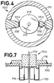
- Fig. 4 is a bottom view of another embodiment of a feed-through system according to the present invention.
- Fig. 5 is a cross-sectional view of another embodiment of a feed-through system according to the present invention.
- Fig. 6 is a cross-sectional view of another embodiment of a feed-through system according to the present invention.
- Fig. 7 is a cross-sectional view of another embodiment of a feed-through system according to the present invention.
- the present invention will be described with reference to a hermetically sealed electronic feed-through system utilizing a feed-through capacitor. It will, however, be recognized by one skilled in the art that the invention may be employed in feed-through systems which do not require hermetic sealing and/or which utilize other electronic or heat sensitive components.
- Fig. 1 is a cross-sectional view of a typical prior art feed-through system 10 utilizing epoxy bonding.
- the feed-through system 10 generally comprises a housing 12, an electrical conductor 13 extending through a hole in an insulator 14.
- a feed-through capacitor 15 is disposed within the housing 12.
- An epoxy layer 16 is employed to secure the feed-through capacitor into housing 12.
- Feed-through capacitor 15 has two electrodes, electrode 17 on an inside surface providing electrical connection to conductor 13 and electrode 18 on the outside surface providing electrical connection to housing 12.
- feed-through system 10 After assembling feed-through system 10, it is typically attached to the wall 20 of a container by high temperature brazing or welding at perimeter 21.
- the temperatures at perimeter 21 can result in a significant transfer of heat along the walls of housing 12 as shown by the arrows in Fig. 1.
- the amount of heat actually transferred from perimeter 21 to the epoxied feed-through capacitor 15 can be sufficient to damage feed-through capacitor 15 or to cause the epoxy bond to fail. This problem is particularly acute in systems in which the feed-through system has a small thermal mass.
- the present invention utilizes an electrically conducting bridge of high thermal resistance to connect the feed-through capacitor to the wall of the feed-through housing while limiting the amount of heat that can flow from the feed-through wall to the capacitor during the attachment of the feed-through system to the container.
- the present invention also avoids the necessity of using epoxy resins.
- Feed-through system 100 provides a conducting path for conductor 113 through the wall 120 of a container via insulator 114.
- Feed-through system 100 is adapted for connection to wall 120 by welding of housing 112 to the wall 120.
- Housing 112 and electrically conducting bridge 130 provides the electrical connection between wall 120 and the outer surface electrode of feed-through capacitor 115.
- Capacitor 115 has a second electrode disposed on the inside surface of region 117 that is connected to lead 113 by the application of a conductive bonding agent.
- Bridge 130 has three regions. The first region 131 connects the bridge to housing 112. The second region 133 connects the bridge to feed-through capacitor 115. Between regions 131 and 133 the third region 132 provides a thermally resistant electrical connection between regions 131 and 133. In the preferred embodiment of the present invention, the cross-sectional area of region 132 is considerably less than the cross-sectional area of housing 112. Hence, the thermal resistance of region 132 is substantially greater than that of housing 112. The region of increased thermal resistance impedes the flow of heat from housing 112 to feed-through capacitor 115 during the attachment of feed-through system 100 to container 120. Bridge 130 may be constructed from any electrically conducting material. In one embodiment of the present invention, the housing 112 is made of titanium and the bridge 130 is constructed from a nickel ribbon.
- the housing and bridge components are not as important as their thicknesses.
- the bridge thickness is 20% or less of the housing thickness.
- the bridge completely surrounds the feed-through capacitor as shown in Fig. 3 which is a bottom view of a feed-through system 200 according to the present invention.
- a bridge comprising regions 231-233 is electrically connected and bonded to housing 212 of feed-through system 200 by bonding region 231.
- the bridge is electrically connected and bonded to the outer electrode of feed-through capacitor 215 by bonding region 233.
- Region 232 of the bridge provides a thermally resistant electrical connection between regions 231 and 233.
- Feed-through capacitor 215 has a hole therein for connection to lead 213.
- the arrangement shown in Fig. 3 is preferred because the bridge provides a shield against electromagnetic radiation. That is, there is no possibility of electromagnetic radiation passing between feed-through capacitor 215 and housing 212. However, this arrangement does not minimize the cross-sectional area of region 232; hence, it does not provide the maximum thermal isolation.
- FIG. 4 A bottom view of a second embodiment of the present invention that provides improved thermal isolation is shown in Fig. 4 at 300.
- the bridge region 332 consists of thin ribbon extending from the housing 312 of the feed-through to the outer electrode of feed-through capacitor 315.
- the centre electrode of feed-through capacitor 315 is connected to conductor 313.
- region 332 may be controlled by changing the cross-sectional area of the region and/or by changing the material from which the region is constructed.
- the cross-sectional area may be reduced by cutting notches in region 332 to form a small restricted bridge region as shown at 355.
- region 332 or region 355 could be constructed from a material having a higher thermal resistivity than housing 312.
- connection to feed-through capacitor 315 may be made with the aid of spot welds such as those shown at 350.
- spot weld' shall be defined to include any method of attachment in which a small conducting area is created between two surfaces. Small areas of brazing alloys or other conductive bonding agents may be present between the two surfaces.
- the spot welds further limit the cross-sectional area of the bridge that is available to transfer heat to feed-through capacitor 315.
- spot welds may be introduced between feed-through housing 312 and the portion of region 332 that is adjacent thereto.
- This method of spot welding to provide a thermal fuse provides some additional advantages, since the bridge has a high thermal resistance the temperature at which the weld is designed to fail may then be greater than that of the weld shown at 350. There are more choices of alloys for the spot welds if the failure temperature is higher.
- thermal fuse can be provided by region 332 or region 355. This may be accomplished by utilizing a material that melts when subjected to heating beyond a predetermined temperature.
- the feed-through capacitor may be positioned adjacent to the insulator 114 as shown in Fig. 2 or it may be spaced therefrom as shown in Figs. 5 and 6.
- a spacer 540 may be used to set the distance between the feed-through capacitor shown at 515 and the insulator.
- one or more ports such as port 646 accessing the portion of lead 613 within space 645 may be provided. This port may be used to visually inspect lead 613 or make test connections thereto. Such ports may also be used to inspect the insulator 614 during testing of the hermetic seal or to inspect the hidden side of capacitor 615.
- Figs. 4-6 also allows for the use of a flexible bridge to accommodate any thermal expansion mis-match during the attachment of the feed-through system to the container.
- feed-through housing 112 provides structural support for attaching bridge 130 and, in combination with bridge 130, provides a ground shield that isolates the portion of lead 113 that passes through insulator 114. In addition, the ground shield prevents electromagnetic radiation from escaping from the container via insulator 114.
- bridge 130 may also provide these functions as shown at 700 in Fig. 7.
- bridge 730 connects to feed-through base member 712 which does not house feed-through capacitor 715.
- Bridge 730 provides the electrical shielding of feed-through capacitor 715 and lead 713. The construction of bridge 730 provides a very long pathway for heat transfer (1 in Fourier's equation is large) and so reduces heat flow considerably.
Landscapes
- Engineering & Computer Science (AREA)
- Power Engineering (AREA)
- Manufacturing & Machinery (AREA)
- Microelectronics & Electronic Packaging (AREA)
- Fuses (AREA)
- Extrusion Moulding Of Plastics Or The Like (AREA)
- Diaphragms For Electromechanical Transducers (AREA)
- Fixed Capacitors And Capacitor Manufacturing Machines (AREA)
- Control Of Transmission Device (AREA)
- Input Circuits Of Receivers And Coupling Of Receivers And Audio Equipment (AREA)
- Preparation Of Compounds By Using Micro-Organisms (AREA)
- Inorganic Insulating Materials (AREA)
- Mounting Components In General For Electric Apparatus (AREA)
- Shaping Of Tube Ends By Bending Or Straightening (AREA)
- Thermistors And Varistors (AREA)
Abstract
Description
- The present invention relates to electronic components, and, more particularly, an improved feed-through system for applications requiring the mounting of electronic components on or near the feed-through, see for example WO-A-9 101 565.
- Feed-throughs are well known in industry and are commonly used to provide electrically conductive paths through walls of articles. In many instances, unwanted high-frequency signals generated to one side of a wall pass through the feed-through and cause problems for circuitry situated on the other side of the wall.
- In an effort to alleviate interference from such sources, various filtering devices and/or techniques have been employed, such as ceramic capacitors. Feed-throughs with capacitors are intended primarily to pass relatively low frequency electrical signals via a lead or conductor through an opening in a conducting wall, screen or the like while presenting a low impedance shunt path to the conducting wall for high frequency signals. Capacitors of this type are disclosed in U.S. Patent Nos. 3,243,671 and 2,756,375.
- This type of feed-through arrangement is commonly used in electronic systems such as heart pacemakers, missiles, satellites and space probes. Illustrative are the feed-through capacitor systems disclosed in U.S. Patent Nos. 5,032,692, 4,424,551, 4,314,213 and 4,148,003.
- To maximize the effectiveness of such filter systems, the feed-through capacitor must be mounted as close to the feed-through as possible. The outside surface of the capacitor is typically covered by a metallic electrode that is connected to the container wall. By positioning the capacitor adjacent to the feed-through, the capacitor becomes a continuation of the container wall. In effect, the container wall 'covers' most of the insulator when the capacitor is so positioned. If the high-frequency filter is mounted on a circuit board in the container, the lead from the filter to the feed-through can act as an antenna which collects and transmits the high frequency electromagnetic radiation present in the container. Hence, the length of unshielded conductor from the final filter to the wall of the container must be minimized. One method for accomplishing this goal makes use of a feed-through capacitor mounted on the feed-through.
- The above described system requires that the capacitor be attached to the feed-through. One method for providing this attachment relies on bonding the capacitor to the feed-through using epoxy resin. This approach has a number of drawbacks. Firstly, epoxies are difficult to apply, particularly on small packages. This results in high labour costs and low yields. Secondly, epoxies are unstable at temperatures above 175°C. Such temperatures are often encountered when a feed-through assembly is attached to a container via welding or brazing. Thirdly, it is difficult to inspect the assembled part.
- One alternative to epoxy attachment is disclosed in U.S. Patent No. 5,032,692. In this system the capacitor attachment is achieved through the use of brazing alloy rings. The capacitor is brazed into a shielded compartment in the feed-through. While this method eliminates the use of epoxies, it requires capacitors that are capable of withstanding very high temperatures. The use of such capacitors increases the cost of the feed-through system.
- The present invention provides an electronic feed-through system for a conductor comprising:-
- an electrically conductive base adapted for attachment to a structure by a process utilizing heat;
- an electronic component mounted by electrically conductive bridge means in spaced relationship to the conductive base, the electrically conductive base and electrical component being separated by a gap;
- the electrically conductive bridge means having a thermal resistance greater than the thermal resistance of the electrically conductive base, and bridging the gap between and electrically connecting the conductive base and the electronic component.
- Further features and advantages will become apparent from the following description of embodiments of the invention, as illustrated in the accompanying schematic drawings, in which:
- Fig.1 is a cross-sectional view of a prior art feed-through system.
- Fig. 2 is a cross-sectional view of a feed-through system according to the present invention.
- Fig. 3 is a bottom view of a feed-through system according to the present invention.
- Fig. 4 is a bottom view of another embodiment of a feed-through system according to the present invention.
- Fig. 5 is a cross-sectional view of another embodiment of a feed-through system according to the present invention.
- Fig. 6 is a cross-sectional view of another embodiment of a feed-through system according to the present invention.
- Fig. 7 is a cross-sectional view of another embodiment of a feed-through system according to the present invention.
- The present invention will be described with reference to a hermetically sealed electronic feed-through system utilizing a feed-through capacitor. It will, however, be recognized by one skilled in the art that the invention may be employed in feed-through systems which do not require hermetic sealing and/or which utilize other electronic or heat sensitive components.
- The manner in which the present invention achieves its advantages over the prior art may be more easily understood with reference to Fig. 1 which is a cross-sectional view of a typical prior art feed-through
system 10 utilizing epoxy bonding. The feed-through system 10 generally comprises ahousing 12, anelectrical conductor 13 extending through a hole in aninsulator 14. A feed-through capacitor 15 is disposed within thehousing 12. Anepoxy layer 16 is employed to secure the feed-through capacitor intohousing 12. Feed-throughcapacitor 15 has two electrodes,electrode 17 on an inside surface providing electrical connection toconductor 13 andelectrode 18 on the outside surface providing electrical connection tohousing 12. - After assembling feed-through
system 10, it is typically attached to thewall 20 of a container by high temperature brazing or welding atperimeter 21. The temperatures atperimeter 21 can result in a significant transfer of heat along the walls ofhousing 12 as shown by the arrows in Fig. 1. The amount of heat actually transferred fromperimeter 21 to the epoxied feed-throughcapacitor 15 can be sufficient to damage feed-throughcapacitor 15 or to cause the epoxy bond to fail. This problem is particularly acute in systems in which the feed-through system has a small thermal mass. - The present invention utilizes an electrically conducting bridge of high thermal resistance to connect the feed-through capacitor to the wall of the feed-through housing while limiting the amount of heat that can flow from the feed-through wall to the capacitor during the attachment of the feed-through system to the container. The present invention also avoids the necessity of using epoxy resins.
- Refer now to Fig. 2 which is a cross-sectional view of a feed-
through system 100 according to the present invention. [In Fig. 2 and subsequent Figs, elements that serve analogous functions to elements shown in Fig. 1 have been assigned numbers that differ from those in Fig. 1 by 100,200, etc.] Feed-throughsystem 100 provides a conducting path forconductor 113 through thewall 120 of a container viainsulator 114. Feed-throughsystem 100 is adapted for connection towall 120 by welding ofhousing 112 to thewall 120.Housing 112 and electrically conducting bridge 130 provides the electrical connection betweenwall 120 and the outer surface electrode of feed-throughcapacitor 115. -
Capacitor 115 has a second electrode disposed on the inside surface of region 117 that is connected tolead 113 by the application of a conductive bonding agent. - Bridge 130 has three regions. The
first region 131 connects the bridge tohousing 112. Thesecond region 133 connects the bridge to feed-throughcapacitor 115. Betweenregions third region 132 provides a thermally resistant electrical connection betweenregions region 132 is considerably less than the cross-sectional area ofhousing 112. Hence, the thermal resistance ofregion 132 is substantially greater than that ofhousing 112. The region of increased thermal resistance impedes the flow of heat fromhousing 112 to feed-throughcapacitor 115 during the attachment of feed-throughsystem 100 tocontainer 120. Bridge 130 may be constructed from any electrically conducting material. In one embodiment of the present invention, thehousing 112 is made of titanium and the bridge 130 is constructed from a nickel ribbon. - In the preferred embodiment actual dimensions of the housing and bridge components are not as important as their thicknesses. Preferably the bridge thickness is 20% or less of the housing thickness. The selection of an appropriate bridge thickness and material includes considerations of, among other criteria, cost, manufacturability, and solderability. In general terms, Fourier's Law defines the heat flow.

- q
- = heat flow
- k
- = thermal conductivity
- A
- = cross sectional area of bridge
- 1
- = length of bridge
- ΔT
- = temperature differential between housing and bridge.
- In a preferred embodiment of the present invention, the bridge completely surrounds the feed-through capacitor as shown in Fig. 3 which is a bottom view of a feed-through
system 200 according to the present invention. A bridge comprising regions 231-233 is electrically connected and bonded tohousing 212 of feed-throughsystem 200 by bondingregion 231. The bridge is electrically connected and bonded to the outer electrode of feed-throughcapacitor 215 by bondingregion 233.Region 232 of the bridge provides a thermally resistant electrical connection betweenregions capacitor 215 has a hole therein for connection to lead 213. The arrangement shown in Fig. 3 is preferred because the bridge provides a shield against electromagnetic radiation. That is, there is no possibility of electromagnetic radiation passing between feed-throughcapacitor 215 andhousing 212. However, this arrangement does not minimize the cross-sectional area ofregion 232; hence, it does not provide the maximum thermal isolation. - A bottom view of a second embodiment of the present invention that provides improved thermal isolation is shown in Fig. 4 at 300. In this embodiment, the
bridge region 332 consists of thin ribbon extending from thehousing 312 of the feed-through to the outer electrode of feed-throughcapacitor 315. The centre electrode of feed-throughcapacitor 315 is connected toconductor 313. - The thermal resistance of
region 332 may be controlled by changing the cross-sectional area of the region and/or by changing the material from which the region is constructed. The cross-sectional area may be reduced by cutting notches inregion 332 to form a small restricted bridge region as shown at 355. Similarly,region 332 orregion 355 could be constructed from a material having a higher thermal resistivity thanhousing 312. - The connection to feed-through
capacitor 315 may be made with the aid of spot welds such as those shown at 350. For the purpose of this discussion, the term `spot weld' shall be defined to include any method of attachment in which a small conducting area is created between two surfaces. Small areas of brazing alloys or other conductive bonding agents may be present between the two surfaces. The spot welds further limit the cross-sectional area of the bridge that is available to transfer heat to feed-throughcapacitor 315. By bonding with an alloy that has a sufficiently low melting temperature, the bond may be used as a `thermal fuse' that will break if the feed-through is overheated during attachment to the container. Visual inspection of the bond can then be used to identify components that were overheated during assembly. Thus, parts that might fail in service may be eliminated before being placed in service. - It should also be noted that the spot welds may be introduced between feed-through
housing 312 and the portion ofregion 332 that is adjacent thereto. This method of spot welding to provide a thermal fuse provides some additional advantages, since the bridge has a high thermal resistance the temperature at which the weld is designed to fail may then be greater than that of the weld shown at 350. There are more choices of alloys for the spot welds if the failure temperature is higher. - It should also be noted that the thermal fuse can be provided by
region 332 orregion 355. This may be accomplished by utilizing a material that melts when subjected to heating beyond a predetermined temperature. - The feed-through capacitor may be positioned adjacent to the
insulator 114 as shown in Fig. 2 or it may be spaced therefrom as shown in Figs. 5 and 6. Referring to Fig. 5, aspacer 540 may be used to set the distance between the feed-through capacitor shown at 515 and the insulator. Referring to Fig. 6, if thespace 645 between feed-throughcapacitor 615 andinsulator 614 is not filled by a spacer, one or more ports such asport 646 accessing the portion oflead 613 withinspace 645 may be provided. This port may be used to visually inspect lead 613 or make test connections thereto. Such ports may also be used to inspect theinsulator 614 during testing of the hermetic seal or to inspect the hidden side ofcapacitor 615. - The configuration shown in Figs. 4-6 also allows for the use of a flexible bridge to accommodate any thermal expansion mis-match during the attachment of the feed-through system to the container.
- While the above described embodiments of the present invention have shown a feed-through capacitor housed within a feed-through housing, other configurations will be apparent to those skilled in the art. Referring again to Fig. 2, feed-through
housing 112 provides structural support for attaching bridge 130 and, in combination with bridge 130, provides a ground shield that isolates the portion oflead 113 that passes throughinsulator 114. In addition, the ground shield prevents electromagnetic radiation from escaping from the container viainsulator 114. However, bridge 130 may also provide these functions as shown at 700 in Fig. 7. In this embodiment of the present invention,bridge 730 connects to feed-throughbase member 712 which does not house feed-throughcapacitor 715.Bridge 730 provides the electrical shielding of feed-throughcapacitor 715 and lead 713. The construction ofbridge 730 provides a very long pathway for heat transfer (1 in Fourier's equation is large) and so reduces heat flow considerably. - Although the above described embodiments of the present invention are directed to a feed-through system with one lead, it will be apparent to those skilled in the art that systems having a plurality of leads may also be constructed according to the present invention. It will also be apparent to those skilled in the art that the present invention may also be used to construct feed-through systems in which the feed-through is not cylindrical in shape.
- Similarly, it will be apparent to those skilled in the art that the feed-through capacitor described in the above embodiments of the present invention could be replaced with any electrical component that must be positioned close to the container wall and connected thereto.
Claims (11)
- An electrical feed-through for a conductor comprising:-an electrically conductive base (112, 212, 312, 712) adapted for attachment to a structure by a process utilizing heat;an electronic component (115, 215, 315, 515, 615, 715) mounted by electrically conductive bridge means (130) in spaced relationship to the conductive base, the electrically conductive base and electrical component being separated by a gap;the electrically conductive bridge means having a thermal resistance greater than the thermal resistance of the electrically conductive base, and bridging the gap between and electrically connecting the conductive base and the electronic component.
- An electrical feed-through as claimed in claim 1 in which the bridge has a cross-sectional area 20% or less that of the base.
- An electrical feed-through as claimed in claim 1 or claim 2 in which the base comprises a housing within which the electrical component is mounted.
- An electrical feed-through as claimed in claim 3 in which the housing comprises an aperture having a mouth, the component lying within the aperture, the bridge, component and conductor completely closing the mouth.
- An electrical feed-through as claimed in any of claims 1 to 3 in which the bridge comprises a ribbon.
- An electrical feed-through as claimed in any preceding claim in which the bridge means is connected to the electrically conductive base and/or to the electrical component by spot welds.
- An electrical feed-through as claimed in any preceding claim and comprising a thermal fuse.
- An electrical feed-through as claimed in Claim 7 in which the bridge comprises the thermal fuse.
- An electrical feed-through as claimed in claim 8 in which the bridge is a ribbon and the thermal fuse comprises a constriction in the ribbon.
- An electrical feed-through as claimed in any preceding claim in which the electrically conductive base houses an insulator held in spaced relationship to the electronic component.
- An electrical feed-through as claimed in Claim 10 in which an insulating spacer is disposed between said insulator and electronic component.
Applications Claiming Priority (3)
| Application Number | Priority Date | Filing Date | Title |
|---|---|---|---|
| US87988 | 1993-07-02 | ||
| US08/087,988 US5440447A (en) | 1993-07-02 | 1993-07-02 | High temperature feed-through system and method for making same |
| PCT/GB1994/001428 WO1995001644A1 (en) | 1993-07-02 | 1994-07-01 | A high temperature feed-through system and method for making same |
Publications (2)
| Publication Number | Publication Date |
|---|---|
| EP0706711A1 EP0706711A1 (en) | 1996-04-17 |
| EP0706711B1 true EP0706711B1 (en) | 1997-08-13 |
Family
ID=22208443
Family Applications (1)
| Application Number | Title | Priority Date | Filing Date |
|---|---|---|---|
| EP94918985A Expired - Lifetime EP0706711B1 (en) | 1993-07-02 | 1994-07-01 | A high temperature feed-through system and method for making same |
Country Status (9)
| Country | Link |
|---|---|
| US (1) | US5440447A (en) |
| EP (1) | EP0706711B1 (en) |
| AT (1) | ATE156931T1 (en) |
| AU (1) | AU680515B2 (en) |
| CA (1) | CA2166066A1 (en) |
| DE (1) | DE69404997T2 (en) |
| DK (1) | DK0706711T3 (en) |
| ES (1) | ES2105727T3 (en) |
| WO (1) | WO1995001644A1 (en) |
Families Citing this family (34)
| Publication number | Priority date | Publication date | Assignee | Title |
|---|---|---|---|---|
| AU3299995A (en) * | 1994-10-04 | 1996-04-18 | Medtronic, Inc. | Protective feedthrough |
| US5870272A (en) * | 1997-05-06 | 1999-02-09 | Medtronic Inc. | Capacitive filter feedthrough for implantable medical device |
| US6008980A (en) * | 1997-11-13 | 1999-12-28 | Maxwell Energy Products, Inc. | Hermetically sealed EMI feedthrough filter capacitor for human implant and other applications |
| US6586675B1 (en) | 1999-12-03 | 2003-07-01 | Morgan Advanced Ceramics, Inc. | Feedthrough devices |
| US6882248B2 (en) | 2000-09-07 | 2005-04-19 | Greatbatch-Sierra, Inc. | EMI filtered connectors using internally grounded feedthrough capacitors |
| US6456481B1 (en) | 2001-05-31 | 2002-09-24 | Greatbatch-Sierra, Inc. | Integrated EMI filter-DC blocking capacitor |
| US6567259B2 (en) | 2001-05-31 | 2003-05-20 | Greatbatch-Sierra, Inc. | Monolithic ceramic capacitor with barium titinate dielectric curie point optimized for active implantable medical devices operating at 37° C. |
| CA2446476A1 (en) | 2002-02-28 | 2003-09-04 | Greatbatch-Sierra, Inc. | Emi feedthrough filter terminal assembly utilizing hermetic seal for electrical attachment between lead wires and capacitor |
| US6985347B2 (en) * | 2002-02-28 | 2006-01-10 | Greatbatch-Sierra, Inc. | EMI filter capacitors designed for direct body fluid exposure |
| US7623335B2 (en) * | 2003-02-27 | 2009-11-24 | Greatbatch-Sierra, Inc | Hermetic feedthrough terminal assembly with wire bond pads for human implant applications |
| US7038900B2 (en) * | 2003-02-27 | 2006-05-02 | Greatbatch-Sierra, Inc. | EMI filter terminal assembly with wire bond pads for human implant applications |
| US7765005B2 (en) * | 2004-02-12 | 2010-07-27 | Greatbatch Ltd. | Apparatus and process for reducing the susceptability of active implantable medical devices to medical procedures such as magnetic resonance imaging |
| US7035077B2 (en) * | 2004-05-10 | 2006-04-25 | Greatbatch-Sierra, Inc. | Device to protect an active implantable medical device feedthrough capacitor from stray laser weld strikes, and related manufacturing process |
| JP2006086405A (en) * | 2004-09-17 | 2006-03-30 | Matsushita Electric Ind Co Ltd | Feedthrough capacitor and magnetron |
| US20080036556A1 (en) * | 2006-08-10 | 2008-02-14 | Honeywell International Inc. | Methods and apparatus for installing a feed through filter |
| US9214709B2 (en) | 2010-12-21 | 2015-12-15 | CastCAP Systems Corporation | Battery-capacitor hybrid energy storage system for high temperature applications |
| US8760851B2 (en) | 2010-12-21 | 2014-06-24 | Fastcap Systems Corporation | Electrochemical double-layer capacitor for high temperature applications |
| US12215572B2 (en) | 2010-12-21 | 2025-02-04 | Fastcap Ultracapacitors Llc | Power system for high temperature applications with rechargeable energy storage |
| US9001495B2 (en) | 2011-02-23 | 2015-04-07 | Fastcap Systems Corporation | High power and high energy electrodes using carbon nanotubes |
| CA2838558C (en) | 2011-05-24 | 2022-08-30 | Fastcap Systems Corporation | Power system for high temperature applications with rechargeable energy storage |
| AU2012267770A1 (en) | 2011-06-07 | 2014-01-23 | Fastcap Systems Corporation | Energy storage media for ultracapacitors |
| US9558894B2 (en) | 2011-07-08 | 2017-01-31 | Fastcap Systems Corporation | Advanced electrolyte systems and their use in energy storage devices |
| CN104221110B (en) * | 2011-07-08 | 2019-04-05 | 快帽系统公司 | High temperature energy storage device |
| US20130058004A1 (en) * | 2011-09-01 | 2013-03-07 | Medtronic, Inc. | Feedthrough assembly including underfill access channel and electrically insulating material |
| CN104024573B (en) | 2011-11-03 | 2018-05-15 | 快帽系统公司 | Production logging instrument |
| US10872737B2 (en) | 2013-10-09 | 2020-12-22 | Fastcap Systems Corporation | Advanced electrolytes for high temperature energy storage device |
| EP3084481B8 (en) | 2013-12-20 | 2024-01-03 | Fastcap Systems Corporation | Electromagnetic telemetry device |
| US11270850B2 (en) | 2013-12-20 | 2022-03-08 | Fastcap Systems Corporation | Ultracapacitors with high frequency response |
| CN113539696B (en) | 2014-10-09 | 2024-12-03 | 快帽系统公司 | Nanostructured electrodes for energy storage devices |
| KR102469677B1 (en) | 2015-01-27 | 2022-11-22 | 패스트캡 시스템즈 코포레이션 | Wide temperature range ultracapacitors |
| WO2018102652A1 (en) | 2016-12-02 | 2018-06-07 | Fastcap Systems Corporation | Composite electrode |
| US10350422B2 (en) * | 2017-06-09 | 2019-07-16 | Medtronic, Inc. | Feedthrough assembly including ferrule with tapered extension(s) |
| US11369800B2 (en) | 2017-11-06 | 2022-06-28 | KYOCERA AVX Components Corporation | EMI feedthrough filter terminal assembly containing a laminated insulative seal |
| US11557765B2 (en) | 2019-07-05 | 2023-01-17 | Fastcap Systems Corporation | Electrodes for energy storage devices |
Family Cites Families (15)
| Publication number | Priority date | Publication date | Assignee | Title |
|---|---|---|---|---|
| US2756375A (en) * | 1952-02-06 | 1956-07-24 | Sprague Electric Co | Feed-through capacitors |
| US3266121A (en) * | 1963-02-14 | 1966-08-16 | Illinois Tool Works | Method of making a capacitorresistor construction |
| US3538464A (en) * | 1963-08-20 | 1970-11-03 | Erie Technological Prod Inc | Multiple pin connector having ferrite core stacked capacitor filter |
| US3243671A (en) * | 1965-01-22 | 1966-03-29 | Sprague Electric Co | Ceramic capacitor |
| DE2518831A1 (en) * | 1975-04-28 | 1976-11-04 | Siemens Ag | FEED-THROUGH CAPACITOR |
| DE2526130C3 (en) * | 1975-06-11 | 1978-08-24 | Siemens Ag, 1000 Berlin Und 8000 Muenchen | Process for the production of electrical stacked or layered capacitors |
| US4148003A (en) * | 1977-07-08 | 1979-04-03 | Globe-Union Inc. | Series feed-through capacitor |
| JPS54144146U (en) * | 1978-03-30 | 1979-10-06 | ||
| US4424551B1 (en) * | 1982-01-25 | 1991-06-11 | Highly-reliable feed through/filter capacitor and method for making same | |
| US4660907A (en) * | 1985-06-20 | 1987-04-28 | Kyocera International, Inc. | EMI filter connector block |
| US4887185A (en) * | 1987-12-17 | 1989-12-12 | Murata Manufacturing Co., Ltd. | Through type capacitor |
| US5032692A (en) * | 1989-05-09 | 1991-07-16 | Avx Corporation | Process for manufactoring hermetic high temperature filter packages and the products produced thereby |
| US4950185A (en) * | 1989-05-18 | 1990-08-21 | Amphenol Corporation | Stress isolated planar filter design |
| US4935842A (en) * | 1989-07-12 | 1990-06-19 | Sundstrand Corporation | High current feed-through capacitor |
| JPH03218004A (en) * | 1990-01-23 | 1991-09-25 | Murata Mfg Co Ltd | Feed-through capacitor |
-
1993
- 1993-07-02 US US08/087,988 patent/US5440447A/en not_active Expired - Lifetime
-
1994
- 1994-07-01 CA CA002166066A patent/CA2166066A1/en not_active Abandoned
- 1994-07-01 AU AU70073/94A patent/AU680515B2/en not_active Ceased
- 1994-07-01 DE DE69404997T patent/DE69404997T2/en not_active Expired - Lifetime
- 1994-07-01 EP EP94918985A patent/EP0706711B1/en not_active Expired - Lifetime
- 1994-07-01 AT AT94918985T patent/ATE156931T1/en not_active IP Right Cessation
- 1994-07-01 WO PCT/GB1994/001428 patent/WO1995001644A1/en not_active Ceased
- 1994-07-01 ES ES94918985T patent/ES2105727T3/en not_active Expired - Lifetime
- 1994-07-01 DK DK94918985.6T patent/DK0706711T3/en active
Also Published As
| Publication number | Publication date |
|---|---|
| DE69404997D1 (en) | 1997-09-18 |
| AU7007394A (en) | 1995-01-24 |
| DK0706711T3 (en) | 1998-02-23 |
| US5440447A (en) | 1995-08-08 |
| ES2105727T3 (en) | 1997-10-16 |
| WO1995001644A1 (en) | 1995-01-12 |
| AU680515B2 (en) | 1997-07-31 |
| EP0706711A1 (en) | 1996-04-17 |
| DE69404997T2 (en) | 1998-03-19 |
| ATE156931T1 (en) | 1997-08-15 |
| CA2166066A1 (en) | 1995-01-12 |
Similar Documents
| Publication | Publication Date | Title |
|---|---|---|
| AU680515B2 (en) | A high temperature feed-through system and method for making same | |
| US4614836A (en) | Ground connector for microelectronic circuit case | |
| US5896267A (en) | Substrate mounted filter for feedthrough devices | |
| CA2229596C (en) | Hermetically sealed electrical feedthrough for use with implantable electronic devices | |
| EP1790204B1 (en) | Field device incorporating circuit card assembly as environmental and emi/rfi shield | |
| US8160707B2 (en) | Method and apparatus for minimizing EMI coupling in a feedthrough array having at least one unfiltered feedthrough | |
| US6985347B2 (en) | EMI filter capacitors designed for direct body fluid exposure | |
| US6349025B1 (en) | Leak testable capacitive filtered feedthrough for an implantable medical device | |
| US5825608A (en) | Feed-through filter capacitor assembly | |
| US5041019A (en) | Transition joint for microwave package | |
| EP2429654B1 (en) | Capacitor assembly and associated method | |
| US5109594A (en) | Method of making a sealed transition joint | |
| US4453033A (en) | Lead grounding | |
| US6111198A (en) | Duplex feedthrough and method therefor | |
| JPH08501659A (en) | Hermetically sealed circuit module with conductive cap anchor | |
| US5598966A (en) | Brazed lower vacuum housing for a dewar | |
| US5247134A (en) | Heat-resistant hermetic packages for electronic components | |
| EP0660449A2 (en) | Electrical feedthrough and its manufacture, and apparatus utilizing the feedthrough | |
| US5093989A (en) | Method of making heat-resistant hermetic packages for electronic components | |
| US6028775A (en) | Assemblies of electronic devices and flexible containers thereof | |
| EP0232312A1 (en) | Mass airflow sensor | |
| US6895822B2 (en) | Apparatus and method for interconnecting leads in a high temperature pressure transducer | |
| JPH01168045A (en) | Hermetically sealed circuit device | |
| US4874910A (en) | High lead density vacuum feedthrough | |
| EP0505193B1 (en) | Cover for electrical components package |
Legal Events
| Date | Code | Title | Description |
|---|---|---|---|
| PUAI | Public reference made under article 153(3) epc to a published international application that has entered the european phase |
Free format text: ORIGINAL CODE: 0009012 |
|
| 17P | Request for examination filed |
Effective date: 19960109 |
|
| AK | Designated contracting states |
Kind code of ref document: A1 Designated state(s): AT BE CH DE DK ES FR GB GR IE IT LI LU MC NL PT SE |
|
| GRAG | Despatch of communication of intention to grant |
Free format text: ORIGINAL CODE: EPIDOS AGRA |
|
| 17Q | First examination report despatched |
Effective date: 19960801 |
|
| GRAH | Despatch of communication of intention to grant a patent |
Free format text: ORIGINAL CODE: EPIDOS IGRA |
|
| GRAH | Despatch of communication of intention to grant a patent |
Free format text: ORIGINAL CODE: EPIDOS IGRA |
|
| GRAA | (expected) grant |
Free format text: ORIGINAL CODE: 0009210 |
|
| AK | Designated contracting states |
Kind code of ref document: B1 Designated state(s): AT BE CH DE DK ES FR GB GR IE IT LI LU MC NL PT SE |
|
| PG25 | Lapsed in a contracting state [announced via postgrant information from national office to epo] |
Ref country code: LI Free format text: LAPSE BECAUSE OF FAILURE TO SUBMIT A TRANSLATION OF THE DESCRIPTION OR TO PAY THE FEE WITHIN THE PRESCRIBED TIME-LIMIT Effective date: 19970813 Ref country code: GR Free format text: LAPSE BECAUSE OF FAILURE TO SUBMIT A TRANSLATION OF THE DESCRIPTION OR TO PAY THE FEE WITHIN THE PRESCRIBED TIME-LIMIT Effective date: 19970813 Ref country code: CH Free format text: LAPSE BECAUSE OF FAILURE TO SUBMIT A TRANSLATION OF THE DESCRIPTION OR TO PAY THE FEE WITHIN THE PRESCRIBED TIME-LIMIT Effective date: 19970813 |
|
| REF | Corresponds to: |
Ref document number: 156931 Country of ref document: AT Date of ref document: 19970815 Kind code of ref document: T |
|
| REG | Reference to a national code |
Ref country code: CH Ref legal event code: EP |
|
| ET | Fr: translation filed | ||
| REF | Corresponds to: |
Ref document number: 69404997 Country of ref document: DE Date of ref document: 19970918 |
|
| REG | Reference to a national code |
Ref country code: ES Ref legal event code: FG2A Ref document number: 2105727 Country of ref document: ES Kind code of ref document: T3 |
|
| PG25 | Lapsed in a contracting state [announced via postgrant information from national office to epo] |
Ref country code: PT Effective date: 19971118 |
|
| REG | Reference to a national code |
Ref country code: DK Ref legal event code: T3 |
|
| REG | Reference to a national code |
Ref country code: CH Ref legal event code: PL |
|
| PLBE | No opposition filed within time limit |
Free format text: ORIGINAL CODE: 0009261 |
|
| STAA | Information on the status of an ep patent application or granted ep patent |
Free format text: STATUS: NO OPPOSITION FILED WITHIN TIME LIMIT |
|
| PG25 | Lapsed in a contracting state [announced via postgrant information from national office to epo] |
Ref country code: LU Free format text: LAPSE BECAUSE OF NON-PAYMENT OF DUE FEES Effective date: 19980701 |
|
| 26N | No opposition filed | ||
| PG25 | Lapsed in a contracting state [announced via postgrant information from national office to epo] |
Ref country code: MC Free format text: LAPSE BECAUSE OF NON-PAYMENT OF DUE FEES Effective date: 19990131 |
|
| PGFP | Annual fee paid to national office [announced via postgrant information from national office to epo] |
Ref country code: GB Payment date: 20000613 Year of fee payment: 7 |
|
| PGFP | Annual fee paid to national office [announced via postgrant information from national office to epo] |
Ref country code: SE Payment date: 20000614 Year of fee payment: 7 Ref country code: IE Payment date: 20000614 Year of fee payment: 7 |
|
| PGFP | Annual fee paid to national office [announced via postgrant information from national office to epo] |
Ref country code: AT Payment date: 20000726 Year of fee payment: 7 |
|
| PGFP | Annual fee paid to national office [announced via postgrant information from national office to epo] |
Ref country code: DK Payment date: 20000727 Year of fee payment: 7 |
|
| PGFP | Annual fee paid to national office [announced via postgrant information from national office to epo] |
Ref country code: NL Payment date: 20000731 Year of fee payment: 7 |
|
| PGFP | Annual fee paid to national office [announced via postgrant information from national office to epo] |
Ref country code: BE Payment date: 20000801 Year of fee payment: 7 |
|
| PG25 | Lapsed in a contracting state [announced via postgrant information from national office to epo] |
Ref country code: GB Free format text: LAPSE BECAUSE OF NON-PAYMENT OF DUE FEES Effective date: 20010701 Ref country code: DK Free format text: LAPSE BECAUSE OF NON-PAYMENT OF DUE FEES Effective date: 20010701 Ref country code: AT Free format text: LAPSE BECAUSE OF NON-PAYMENT OF DUE FEES Effective date: 20010701 |
|
| PG25 | Lapsed in a contracting state [announced via postgrant information from national office to epo] |
Ref country code: SE Free format text: LAPSE BECAUSE OF NON-PAYMENT OF DUE FEES Effective date: 20010702 Ref country code: IE Free format text: LAPSE BECAUSE OF NON-PAYMENT OF DUE FEES Effective date: 20010702 |
|
| PG25 | Lapsed in a contracting state [announced via postgrant information from national office to epo] |
Ref country code: BE Free format text: LAPSE BECAUSE OF NON-PAYMENT OF DUE FEES Effective date: 20010731 |
|
| BERE | Be: lapsed |
Owner name: THE MORGAN CRUCIBLE CY P.L.C. Effective date: 20010731 |
|
| PG25 | Lapsed in a contracting state [announced via postgrant information from national office to epo] |
Ref country code: NL Free format text: LAPSE BECAUSE OF NON-PAYMENT OF DUE FEES Effective date: 20020201 |
|
| GBPC | Gb: european patent ceased through non-payment of renewal fee |
Effective date: 20010701 |
|
| EUG | Se: european patent has lapsed |
Ref document number: 94918985.6 |
|
| REG | Reference to a national code |
Ref country code: DK Ref legal event code: EBP |
|
| NLV4 | Nl: lapsed or anulled due to non-payment of the annual fee |
Effective date: 20020201 |
|
| REG | Reference to a national code |
Ref country code: IE Ref legal event code: MM4A |
|
| PGFP | Annual fee paid to national office [announced via postgrant information from national office to epo] |
Ref country code: ES Payment date: 20100813 Year of fee payment: 17 |
|
| PGFP | Annual fee paid to national office [announced via postgrant information from national office to epo] |
Ref country code: IT Payment date: 20100717 Year of fee payment: 17 Ref country code: FR Payment date: 20100805 Year of fee payment: 17 Ref country code: DE Payment date: 20100630 Year of fee payment: 17 |
|
| REG | Reference to a national code |
Ref country code: FR Ref legal event code: ST Effective date: 20120330 |
|
| PG25 | Lapsed in a contracting state [announced via postgrant information from national office to epo] |
Ref country code: FR Free format text: LAPSE BECAUSE OF NON-PAYMENT OF DUE FEES Effective date: 20110801 Ref country code: DE Free format text: LAPSE BECAUSE OF NON-PAYMENT OF DUE FEES Effective date: 20120201 |
|
| REG | Reference to a national code |
Ref country code: DE Ref legal event code: R119 Ref document number: 69404997 Country of ref document: DE Effective date: 20120201 |
|
| PG25 | Lapsed in a contracting state [announced via postgrant information from national office to epo] |
Ref country code: IT Free format text: LAPSE BECAUSE OF NON-PAYMENT OF DUE FEES Effective date: 20110701 |
|
| REG | Reference to a national code |
Ref country code: ES Ref legal event code: FD2A Effective date: 20121122 |
|
| PG25 | Lapsed in a contracting state [announced via postgrant information from national office to epo] |
Ref country code: ES Free format text: LAPSE BECAUSE OF NON-PAYMENT OF DUE FEES Effective date: 20110702 |