EP0706681B1 - Aircraft frequency adaptive modal suppression system - Google Patents
Aircraft frequency adaptive modal suppression system Download PDFInfo
- Publication number
- EP0706681B1 EP0706681B1 EP94919324A EP94919324A EP0706681B1 EP 0706681 B1 EP0706681 B1 EP 0706681B1 EP 94919324 A EP94919324 A EP 94919324A EP 94919324 A EP94919324 A EP 94919324A EP 0706681 B1 EP0706681 B1 EP 0706681B1
- Authority
- EP
- European Patent Office
- Prior art keywords
- filter
- aircraft
- gross weight
- variable
- frequency
- Prior art date
- Legal status (The legal status is an assumption and is not a legal conclusion. Google has not performed a legal analysis and makes no representation as to the accuracy of the status listed.)
- Expired - Lifetime
Links
Images


Classifications
-
- G—PHYSICS
- G05—CONTROLLING; REGULATING
- G05D—SYSTEMS FOR CONTROLLING OR REGULATING NON-ELECTRIC VARIABLES
- G05D1/00—Control of position, course or altitude of land, water, air, or space vehicles, e.g. automatic pilot
- G05D1/08—Control of attitude, i.e. control of roll, pitch, or yaw
- G05D1/0808—Control of attitude, i.e. control of roll, pitch, or yaw specially adapted for aircraft
- G05D1/0816—Control of attitude, i.e. control of roll, pitch, or yaw specially adapted for aircraft to ensure stability
- G05D1/0825—Control of attitude, i.e. control of roll, pitch, or yaw specially adapted for aircraft to ensure stability using mathematical models
Definitions
- the present invention relates to a system for aircraft modal suppression, comprising:
- a drawback of the system is that it does not fully compensate for body bending modes when airplane weight differs from the Design Gross Weight (DGW) due to fuel consumption.
- DGW Design Gross Weight
- DGW Design Gross Weight
- the system for aircraft modal suppression is therefore characterized in that weight means coupled to said filter means are provided for providing a gross weight signal representative of the gross weight of the aircraft;
- the weight means comprise a Flight Management Computer (FMC).
- FMC Flight Management Computer
- variable filter means comprise a notch filter having a frequency and widths and depths which vary according to the gross weight of the aircraft.
- variable filter means comprise a notch filter having a frequency range determined by the sweeping of the rotor of the aircraft at the aircraft's heaviest and lightest gross weights.
- system also comprise a variable yaw damper notch filter.
- system also comprises:
- the body bending modes are the dominant structural modes of the airplane in the lateral axis.
- the vibration level of the structural modes are quite high, such that they cause ride discomfort.
- Numerous attempts to solve the ride quality problem prior to the present method embodiment of the invention are: The MSAS system using a gyro to measure yaw rate for feedback in the 70s; the use of a single fixed frequency notch filter located in the output of the basic yaw damper, called the passive control system in 1985; the multiple fixed frequency notch filter in conjunction with the fixed frequency active filters, called aircraft modal suppression system developed in 1987, 1988, and in 1989.
- FIG. 1 is the detailed block diagram illustrating current modal suppression system used in aircraft.
- the current modal suppression system is not fully satisfactory in suppressing the body bending modes when the gross weight of the airplane is different from the design gross weight because:
- the frequency of the body bending mode varies depending on the gross weight of the airplane.
- the difference in gross weight between the lightest and heaviest long range airplane is more than 200,000 Ibs.
- the frequency of its first body bending mode varies from around 2.8 to 3.5 Hz.
- the present frequency adaptive modal suppression system deals with the variation in frequency, which results in variation in phase, of the body bending mode.
- the present preferred embodiment of the invention brings in the airplane gross weight signal from the flight management computer, which action enables both the passive and active control systems to accurately adapt to the frequency of the body bending modes and produce the precise control signals.
- FIG. 2 is the detailed block diagram illustrating the preferred single accelerometer modal suppression system according to a preferred embodiment of the present invention. While the frequency (coefficients) of the basic yaw damper notch filter (3.5 Hz notch filter) in the current aircraft basic yaw damper is fixed at 3.5 Hz; the coefficients K1, K2, and K3 (see Table 1) of the basic yaw damper notch filter, in accordance with a preferred embodiment of this invention, is tabulated as a function of airplane gross weight. This enables not only the frequency (K3) but also the width and depth (K1/K2) of the notch filter to vary according to the gross weight of the airplane.
- the frequency range of the body bending modes (same as the frequency range of the notch filter) is determined by sweeping the rudder of the airplane at its heaviest and lightest gross weights.
- the heaviest gross weight airplane has the first body bending mode at the lowest frequency; the lightest gross weight airplane has the first body bending mode at the highest frequency.
- the sweep process was produced by using a frequency function generator (FFG) to drive the yaw damper servo with a frequency varying (either ascending or descending) sine wave (or other wave forms) signal at a predetermined rate for a predetermined period of time.
- the servo in tum, will drive the rudder of the airplane to create an oscillation throughout the predetermined frequency range.
- the time response (history) of the acceleration of the aft (and/or forward) station will be collected and transformed into the frequency domain where the frequency of the body bending mode is read.
- the intermediate frequencies of the body bending mode can be determined by using the same sweeping process for the airplane with gross weights in between. These intermediate frequencies can also be obtained by linearizing the frequency points between the minimum and maximum frequencies if sweeping of the airplane becomes too expensive. Since the gross weight of the airplane changes slowly, the number of frequency points between minimum and maximum frequencies can be chosen to be infinite. However, an increment of .1 Hz from the minimum to the maximum frequencies is usually used to select the frequency points and their corresponding gross weight ranges (GWR), as shown hereinafter.
- GWR gross weight ranges
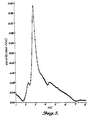
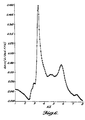
- FIGS. 5 and 6 present the body bending mode of the airplane with heavy and light gross weights, respectively. It is apparent that the frequency of the body bending mode is gross weight dependent.
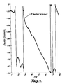
- FIGS. 7 and 8 show that the phase of the body bending mode varies dramatically depending on the weight of the airplane.
- the phase difference of the body bending mode between these particular light and heavy airplanes is 72 degrees at 3 Hz. This is critical, since the control theory behind the aircraft modal suppression system is based on the phase relationships of the control law and the body bending mode to generate the control signal. If the phase of the body bending mode varies while the phase of the filter is fixed, the modal suppression system will not be able to drive the control surface at the right time in order to suppress the acceleration. Driving the control surface at a wrong time may excite the modes or cause the airplane to go unstable, depending on the magnitude of the control signal.
- the active filter By bringing in the gross weight signal as a gain table for the coefficients Ao,..., Ap and Bo,..., Bq (see FIG. 2 and FIG. 4, Table 2,), the active filter will be able to match its phase with the phase variation of the body bending modes to generate the proper control signal to suppress the body bending modes.
- Gain tabulating of the coefficients is not limited to the present aircraft frequency adaptive modal suppression system with one accelerometer, but can be extended to more than one accelerometer as well as many order filters, depending on the memory size and speed of the microprocessor which is used for the frequency adaptive modal suppression system.
- Gr is a multiple gain schedule which consists of G1 to Gn for n gross weight ranges. In other words, each GWR will have an active filter with its corresponding G gain.
- FIG. 1 is a detailed block diagram illustrating the prior aircraft modal suppression system and the basic yaw damper, which are similar to FIGS. 5 and 6 of U.S. Patent No. 5,072,893, the details of which are incorporated herein by reference with FIG. 2 herein utilizing corresponding numeral for corresponding circuit elements.
- FIG. 2 is a detailed block diagram illustrating the modal suppression system and the basic yaw damper in accordance with the preferred embodiment of the present invention.
- the differences between the present invention and the system shown in U.S. Patent No. 5,072,893 are discussed in more detail hereinafter.
- the present invention incorporates the gross weight signal 28 from the aircraft's on-board flight management computer. This signal is passed through a .5 rad/s low pass filter 30 to filter out any high frequency noise. The filtered gross weight signal is then sent to the variable filter 34, multiple gain schedule 36, and the variable notch filter 72 for filter and gain selection purpose.
- 5,072,893 is digitized, then passed through an anti-aliasing filter 12 which is designed to eliminate the aliasing effect of digitization.
- the digital output from the anti-aliasing filter 12 is passed to the common fixed jth order filter 32 where j is only limited by the frame time of the on-board microprocessor.
- the common fixed filter 32 is the common factor which is pulled out of the multiple path called variable filter 34 in order to reduce the total order of the modal suppression system.
- the common fixed filter accelerometer signal 32 is then passed to a variable filter 34 where switching (filter selection) takes place based on the gross weight of the airplane (detailed in FIG. 4).
- the output of the variable filter 34 is passed to the multiple gain schedule block 36 (detailed in FIG. 4) where only the corresponding gain schedule is activated before being summed with the basic yaw damper command.
- FIG. 4 is the expansion of the general form of the multiple gain schedule 10 and the variable notch filter 20.
- This is basically a multiple path where each path, represented by a filter and its corresponding gain schedule, is assigned to a gross weight range and selected when the filtered gross weight signal falls in the weight range.
- a single path can be constructed by filling in the general form 20 with a sub-coefficient a 0,1 22, a 1,1 24,...a p,1 28, b 0,1 30, b 1,1 32,... b q,1 36.
- the shape of each path can be altered by its variable filter, the main function of the variable filter is to provide the proper phase for the system in order to deal with the variation in frequency of the body bending mode.
- n sets of gain schedule G1 ... Gn signal from the modal suppression system will be passed to the rudder of the aircraft, and since the force produced by the rudder is a function of impact pressure qc which is a function of speed, altitude, and temperature, the acceleration signal is gain amplified by a gain factor G(1, or . .n) which decreases in value as the impact pressure qc increases.
- FIG. 5 is the frequency response graph in magnitude of the lateral acceleration at the aft station which shows that the frequency at the peak of the body bending mode of the heavy airplane is at 2.85 Hz.
- FIG. 6 shows that the same airplane at light weight has the peak of the body bending mode is at 3.4 Hz.
- FIG. 7 is the phase graph of the lateral acceleration at the aft station for the heavy weight which has a phase angle of -72 degrees at 3 Hz.
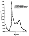
- FIG. 8 shows the variation in phase from the heavy weight to light weight airplane.
- the same airplane at light weight has the phase of 0 degree at 3 Hz.
- FIGS. 9 and 10 are the frequency response graphs in magnitude illustrating the improvement in the lateral acceleration for both the heavy and light weight airplanes when using the present aircraft frequency adaptive modal suppression system.
Description
G(1, or . .n) which decreases in value as the impact pressure qc increases.
Claims (6)
- System for aircraft modal suppression, comprising:characterized in that weight means (28) coupled to said filter means are provided for providing a gross weight signal representative of the gross weight of the aircraft; and/orcontrol surface means responsive to input control signals;filter means coupled to said control surface means for shaping an input control signal;sensor means coupled to said filter means for producing an excitation signal representative of excitation of the body in at least one body bending mode of the aircraft;in that the filter means comprise a variable filter (34, 36, 72) selecting in response to said gross weight signal at least a predetermined coefficient and gain schedule thereby causing a phase matching the phase variation of the body bending modes of the aircraft.
- System according to claim 1, wherein the weight means (28) comprise a flight management computer.
- System according to claim 1 or 2, wherein said variable filter means comprise a notch filter (72) having a frequency and width and depth which vary according to the gross weight of the aircraft.
- System according to one of the preceding claims, wherein said variable filter means comprise a notch filter (72) having a frequency range determined by the sweeping the control surface of the aircraft at the aircraft's heaviest and lightest gross weights.
- System according to one of the preceding claims, also comprising a variable yaw damper notch filter (72).
- System according to one of the preceding claims, comprising:means (32) for providing a common fixed filter accelerometer signal;a variable filter (34) responsive to said common fixed filter accelerometer signal;said variable filter having filter selection responsive to gross weight of the aircraft; andsaid variable filter (34) having an output coupled through summing means (74) with a yaw damper command for controlling the aircraft.
Applications Claiming Priority (3)
| Application Number | Priority Date | Filing Date | Title |
|---|---|---|---|
| US08/086,447 US5452865A (en) | 1993-06-28 | 1993-06-28 | Aircraft frequency adaptive modal suppression system |
| US86447 | 1993-06-28 | ||
| PCT/US1994/006193 WO1995000891A1 (en) | 1993-06-28 | 1994-06-01 | Aircraft frequency adaptive modal suppression system |
Publications (2)
| Publication Number | Publication Date |
|---|---|
| EP0706681A1 EP0706681A1 (en) | 1996-04-17 |
| EP0706681B1 true EP0706681B1 (en) | 1999-10-20 |
Family
ID=22198631
Family Applications (1)
| Application Number | Title | Priority Date | Filing Date |
|---|---|---|---|
| EP94919324A Expired - Lifetime EP0706681B1 (en) | 1993-06-28 | 1994-06-01 | Aircraft frequency adaptive modal suppression system |
Country Status (6)
| Country | Link |
|---|---|
| US (2) | US5452865A (en) |
| EP (1) | EP0706681B1 (en) |
| JP (1) | JPH08511752A (en) |
| AU (1) | AU7050894A (en) |
| DE (1) | DE69421279T2 (en) |
| WO (1) | WO1995000891A1 (en) |
Families Citing this family (16)
| Publication number | Priority date | Publication date | Assignee | Title |
|---|---|---|---|---|
| US5452865A (en) * | 1993-06-28 | 1995-09-26 | The Boeing Company | Aircraft frequency adaptive modal suppression system |
| US5667166A (en) * | 1995-01-12 | 1997-09-16 | The Boeing Company | Aircraft frequency adaptive modal suppression system |
| US6539290B1 (en) * | 1995-06-07 | 2003-03-25 | Dabulamanzi Holdings, Llc | Method, apparatus and design procedure for controlling multi-input, multi-output (MIMO) parameter dependent systems using feedback LTI'zation |
| US5833173A (en) * | 1996-02-13 | 1998-11-10 | The Boeing Company | Aircraft frequency adaptive modal suppression system |
| US5839697A (en) * | 1996-05-14 | 1998-11-24 | The Boeing Company | Method and apparatus for turn coordination gain as a function of flap position |
| US6288380B1 (en) * | 2000-04-10 | 2001-09-11 | The United States Of America As Represented By The Secretary Of The Navy | Adaptive body-bending estimator for use with a missile during flight |
| US6915989B2 (en) * | 2002-05-01 | 2005-07-12 | The Boeing Company | Aircraft multi-axis modal suppression system |
| FR2853094B1 (en) * | 2003-03-26 | 2005-05-27 | Airbus France | METHOD FOR CONTROLLING VIBRATION INDUCED IN AN AIRCRAFT BY THE ROTATING OPERATION OF A BLOWER AND ELECTRIC FLIGHT CONTROL SYSTEM USING THE SAME |
| EP2146263B1 (en) | 2003-11-03 | 2019-05-08 | The Boeing Company | Aircraft multi-axis modal suppression system |
| US7722322B2 (en) * | 2004-08-30 | 2010-05-25 | Lord Corporation | Computer system and program product for controlling vibrations |
| US8267652B2 (en) * | 2004-08-30 | 2012-09-18 | Lord Corporation | Helicopter hub mounted vibration control and circular force generation systems for canceling vibrations |
| US8162606B2 (en) | 2004-08-30 | 2012-04-24 | Lord Corporation | Helicopter hub mounted vibration control and circular force generation systems for canceling vibrations |
| US7448854B2 (en) | 2004-08-30 | 2008-11-11 | Lord Corporation | Helicopter vibration control system and rotary force generator for canceling vibrations |
| US7367530B2 (en) * | 2005-06-21 | 2008-05-06 | The Boeing Company | Aerospace vehicle yaw generating systems and associated methods |
| KR101486721B1 (en) | 2007-10-25 | 2015-01-28 | 로드코포레이션 | Distributed active vibration control systems and rotary wing aircraft with suppressed vibrations |
| EP3643605B1 (en) | 2018-10-25 | 2022-08-17 | Bombardier Inc. | System and method for mitigating an effect of an excitation of a structural flexible mode of an aircraft |
Family Cites Families (14)
| Publication number | Priority date | Publication date | Assignee | Title |
|---|---|---|---|---|
| US3643073A (en) * | 1967-09-18 | 1972-02-15 | Honeywell Inc | Transfer function monitoring apparatus |
| US3572618A (en) * | 1967-11-01 | 1971-03-30 | Univ Iowa State Res Found Inc | Method for stabilizing aircraft and missiles |
| US3691352A (en) * | 1971-06-09 | 1972-09-12 | Burroughs Corp | Document reading apparatus |
| US3746997A (en) * | 1971-11-16 | 1973-07-17 | Univ Iowa State Res Found Inc | Adaptive digital frequency discriminator |
| US4340870A (en) * | 1980-07-28 | 1982-07-20 | Motorola, Inc. | Efficient higher order mode resonant combiner |
| US4725020A (en) * | 1980-12-09 | 1988-02-16 | The Boeing Company | Control system incorporating structural feedback |
| US4769759A (en) * | 1986-06-16 | 1988-09-06 | Allied-Signal Inc. | Method for developing air data for use in flight control systems |
| US5072893A (en) * | 1987-05-28 | 1991-12-17 | The Boeing Company | Aircraft modal suppression system |
| US5008825A (en) * | 1989-05-01 | 1991-04-16 | Nadkarni Arun A | Apparatus and methods for automatically maintaining aircraft track angle |
| US5060889A (en) * | 1989-05-01 | 1991-10-29 | The Boeing Company | Apparatus and methods for maintaining aircraft track angle during an asymmetric flight condition |
| EP0488428A3 (en) * | 1990-09-24 | 1992-10-14 | The Boeing Company | Apparatus and method for reducing aircraft loads resulting from atmospheric turbulence and gusts |
| US5102072A (en) * | 1990-11-19 | 1992-04-07 | General Dynamics Corporation, Convair Division | Adaptive gain and phase controller for autopilot for a hypersonic vehicle |
| FR2672028B1 (en) * | 1991-01-29 | 1993-05-14 | Aerospatiale | SYSTEM FOR IMPROVING THE FLOATING BEHAVIOR OF AN AIRCRAFT. |
| US5452865A (en) * | 1993-06-28 | 1995-09-26 | The Boeing Company | Aircraft frequency adaptive modal suppression system |
-
1993
- 1993-06-28 US US08/086,447 patent/US5452865A/en not_active Expired - Lifetime
-
1994
- 1994-06-01 DE DE69421279T patent/DE69421279T2/en not_active Expired - Lifetime
- 1994-06-01 JP JP7502843A patent/JPH08511752A/en active Pending
- 1994-06-01 AU AU70508/94A patent/AU7050894A/en not_active Abandoned
- 1994-06-01 EP EP94919324A patent/EP0706681B1/en not_active Expired - Lifetime
- 1994-06-01 WO PCT/US1994/006193 patent/WO1995000891A1/en active IP Right Grant
-
1996
- 1996-12-30 US US08/827,875 patent/US5860625A/en not_active Expired - Lifetime
Also Published As
| Publication number | Publication date |
|---|---|
| JPH08511752A (en) | 1996-12-10 |
| AU7050894A (en) | 1995-01-17 |
| US5860625A (en) | 1999-01-19 |
| DE69421279T2 (en) | 2000-02-03 |
| US5452865A (en) | 1995-09-26 |
| EP0706681A1 (en) | 1996-04-17 |
| DE69421279D1 (en) | 1999-11-25 |
| WO1995000891A1 (en) | 1995-01-05 |
Similar Documents
| Publication | Publication Date | Title |
|---|---|---|
| EP0706681B1 (en) | Aircraft frequency adaptive modal suppression system | |
| EP0293018B1 (en) | Aircraft modal suppression system | |
| US5667166A (en) | Aircraft frequency adaptive modal suppression system | |
| US9027873B2 (en) | System and method for vibration control in a rotorcraft using an adaptive reference model algorithm | |
| US5722620A (en) | Aircraft pitch-axis stability and command augmentation | |
| US5224667A (en) | System enabling the flutter behavior of an aircraft to be improved | |
| GB2059117A (en) | Control system for gas turbine engine | |
| JPH0375399B2 (en) | ||
| US6976656B2 (en) | Method for controlling the flight of an aircraft | |
| US5839697A (en) | Method and apparatus for turn coordination gain as a function of flap position | |
| Britt et al. | Aeroservoelastic analysis of the B-2 bomber | |
| US5730394A (en) | Vertical performance limit compensator | |
| EP0743584B1 (en) | Aircraft vertical position control system | |
| US5833173A (en) | Aircraft frequency adaptive modal suppression system | |
| US4298833A (en) | Apparatus for damping operator induced oscillations of a controlled system | |
| US7548800B2 (en) | Method and computer program product for controlling an aerodynamic vehicle having at least one structural mode | |
| RU2213025C2 (en) | Method and device for regulation of taxiing force in mechanical control system of flying vehicle | |
| JPH0411440B2 (en) | ||
| Broussard et al. | Design and flight testing of a digital optimal control general aviation autopilot | |
| Konig et al. | Integral control of large flexible aircraft | |
| JPH05170184A (en) | Flight control method | |
| Cheng | A high-order, linear time-invariant model for application to higher harmonic control and flight control system interaction | |
| Gill | Design and Evaluation of Flight Control Systems | |
| RU2272747C2 (en) | Adaptive bank angle auto-pilot | |
| Ganet-Schoeller et al. | Gain Scheduled Robust Attitude Control Law for Flexible Launchers Using Eigenstructure Assignment and Hinifnity Techniques |
Legal Events
| Date | Code | Title | Description |
|---|---|---|---|
| PUAI | Public reference made under article 153(3) epc to a published international application that has entered the european phase |
Free format text: ORIGINAL CODE: 0009012 |
|
| 17P | Request for examination filed |
Effective date: 19951030 |
|
| AK | Designated contracting states |
Kind code of ref document: A1 Designated state(s): DE FR GB NL |
|
| 17Q | First examination report despatched |
Effective date: 19980429 |
|
| GRAG | Despatch of communication of intention to grant |
Free format text: ORIGINAL CODE: EPIDOS AGRA |
|
| GRAG | Despatch of communication of intention to grant |
Free format text: ORIGINAL CODE: EPIDOS AGRA |
|
| GRAH | Despatch of communication of intention to grant a patent |
Free format text: ORIGINAL CODE: EPIDOS IGRA |
|
| GRAH | Despatch of communication of intention to grant a patent |
Free format text: ORIGINAL CODE: EPIDOS IGRA |
|
| GRAA | (expected) grant |
Free format text: ORIGINAL CODE: 0009210 |
|
| AK | Designated contracting states |
Kind code of ref document: B1 Designated state(s): DE FR GB NL |
|
| REF | Corresponds to: |
Ref document number: 69421279 Country of ref document: DE Date of ref document: 19991125 |
|
| ET | Fr: translation filed | ||
| PLBE | No opposition filed within time limit |
Free format text: ORIGINAL CODE: 0009261 |
|
| STAA | Information on the status of an ep patent application or granted ep patent |
Free format text: STATUS: NO OPPOSITION FILED WITHIN TIME LIMIT |
|
| 26N | No opposition filed | ||
| REG | Reference to a national code |
Ref country code: GB Ref legal event code: IF02 |
|
| PGFP | Annual fee paid to national office [announced via postgrant information from national office to epo] |
Ref country code: GB Payment date: 20130627 Year of fee payment: 20 Ref country code: DE Payment date: 20130627 Year of fee payment: 20 |
|
| PGFP | Annual fee paid to national office [announced via postgrant information from national office to epo] |
Ref country code: FR Payment date: 20130702 Year of fee payment: 20 |
|
| PGFP | Annual fee paid to national office [announced via postgrant information from national office to epo] |
Ref country code: NL Payment date: 20130626 Year of fee payment: 20 |
|
| REG | Reference to a national code |
Ref country code: DE Ref legal event code: R071 Ref document number: 69421279 Country of ref document: DE |
|
| REG | Reference to a national code |
Ref country code: NL Ref legal event code: V4 Effective date: 20140601 |
|
| REG | Reference to a national code |
Ref country code: GB Ref legal event code: PE20 Expiry date: 20140531 |
|
| PG25 | Lapsed in a contracting state [announced via postgrant information from national office to epo] |
Ref country code: GB Free format text: LAPSE BECAUSE OF EXPIRATION OF PROTECTION Effective date: 20140531 |
|
| PG25 | Lapsed in a contracting state [announced via postgrant information from national office to epo] |
Ref country code: DE Free format text: LAPSE BECAUSE OF EXPIRATION OF PROTECTION Effective date: 20140603 |