EP0706342B1 - Bathing door unit - Google Patents
Bathing door unit Download PDFInfo
- Publication number
- EP0706342B1 EP0706342B1 EP94922089A EP94922089A EP0706342B1 EP 0706342 B1 EP0706342 B1 EP 0706342B1 EP 94922089 A EP94922089 A EP 94922089A EP 94922089 A EP94922089 A EP 94922089A EP 0706342 B1 EP0706342 B1 EP 0706342B1
- Authority
- EP
- European Patent Office
- Prior art keywords
- panel
- roller
- bracket
- door unit
- track
- Prior art date
- Legal status (The legal status is an assumption and is not a legal conclusion. Google has not performed a legal analysis and makes no representation as to the accuracy of the status listed.)
- Expired - Lifetime
Links
- 238000003287 bathing Methods 0.000 title claims abstract description 26
- 230000000284 resting effect Effects 0.000 claims 1
- 239000000853 adhesive Substances 0.000 description 4
- 230000001070 adhesive effect Effects 0.000 description 4
- 238000004140 cleaning Methods 0.000 description 4
- 238000004519 manufacturing process Methods 0.000 description 3
- 230000000712 assembly Effects 0.000 description 2
- 238000000429 assembly Methods 0.000 description 2
- 238000010276 construction Methods 0.000 description 2
- 238000001125 extrusion Methods 0.000 description 2
- 239000012190 activator Substances 0.000 description 1
- 230000000694 effects Effects 0.000 description 1
- 238000012986 modification Methods 0.000 description 1
- 230000004048 modification Effects 0.000 description 1
- 238000007789 sealing Methods 0.000 description 1
- 230000035939 shock Effects 0.000 description 1
Images


Classifications
-
- E—FIXED CONSTRUCTIONS
- E06—DOORS, WINDOWS, SHUTTERS, OR ROLLER BLINDS IN GENERAL; LADDERS
- E06B—FIXED OR MOVABLE CLOSURES FOR OPENINGS IN BUILDINGS, VEHICLES, FENCES OR LIKE ENCLOSURES IN GENERAL, e.g. DOORS, WINDOWS, BLINDS, GATES
- E06B3/00—Window sashes, door leaves, or like elements for closing wall or like openings; Layout of fixed or moving closures, e.g. windows in wall or like openings; Features of rigidly-mounted outer frames relating to the mounting of wing frames
- E06B3/32—Arrangements of wings characterised by the manner of movement; Arrangements of movable wings in openings; Features of wings or frames relating solely to the manner of movement of the wing
- E06B3/50—Arrangements of wings characterised by the manner of movement; Arrangements of movable wings in openings; Features of wings or frames relating solely to the manner of movement of the wing with more than one kind of movement
- E06B3/5054—Arrangements of wings characterised by the manner of movement; Arrangements of movable wings in openings; Features of wings or frames relating solely to the manner of movement of the wing with more than one kind of movement where the sliding and rotating movements are independent of each other
- E06B3/5072—Arrangements of wings characterised by the manner of movement; Arrangements of movable wings in openings; Features of wings or frames relating solely to the manner of movement of the wing with more than one kind of movement where the sliding and rotating movements are independent of each other the horizontal sliding wings having the possibility of an additional rotational movement
-
- A—HUMAN NECESSITIES
- A47—FURNITURE; DOMESTIC ARTICLES OR APPLIANCES; COFFEE MILLS; SPICE MILLS; SUCTION CLEANERS IN GENERAL
- A47K—SANITARY EQUIPMENT NOT OTHERWISE PROVIDED FOR; TOILET ACCESSORIES
- A47K3/00—Baths; Douches; Appurtenances therefor
- A47K3/28—Showers or bathing douches
- A47K3/30—Screens or collapsible cabinets for showers or baths
- A47K3/36—Articulated screens
- A47K3/362—Articulated screens comprising sliding and articulated panels
-
- E—FIXED CONSTRUCTIONS
- E05—LOCKS; KEYS; WINDOW OR DOOR FITTINGS; SAFES
- E05D—HINGES OR SUSPENSION DEVICES FOR DOORS, WINDOWS OR WINGS
- E05D11/00—Additional features or accessories of hinges
- E05D11/10—Devices for preventing movement between relatively-movable hinge parts
- E05D11/1028—Devices for preventing movement between relatively-movable hinge parts for maintaining the hinge in two or more positions, e.g. intermediate or fully open
- E05D11/1078—Devices for preventing movement between relatively-movable hinge parts for maintaining the hinge in two or more positions, e.g. intermediate or fully open the maintaining means acting parallel to the pivot
-
- E—FIXED CONSTRUCTIONS
- E05—LOCKS; KEYS; WINDOW OR DOOR FITTINGS; SAFES
- E05D—HINGES OR SUSPENSION DEVICES FOR DOORS, WINDOWS OR WINGS
- E05D15/00—Suspension arrangements for wings
- E05D15/56—Suspension arrangements for wings with successive different movements
- E05D15/58—Suspension arrangements for wings with successive different movements with both swinging and sliding movements
-
- E—FIXED CONSTRUCTIONS
- E05—LOCKS; KEYS; WINDOW OR DOOR FITTINGS; SAFES
- E05D—HINGES OR SUSPENSION DEVICES FOR DOORS, WINDOWS OR WINGS
- E05D15/00—Suspension arrangements for wings
- E05D15/48—Suspension arrangements for wings allowing alternative movements
-
- E—FIXED CONSTRUCTIONS
- E05—LOCKS; KEYS; WINDOW OR DOOR FITTINGS; SAFES
- E05D—HINGES OR SUSPENSION DEVICES FOR DOORS, WINDOWS OR WINGS
- E05D15/00—Suspension arrangements for wings
- E05D15/56—Suspension arrangements for wings with successive different movements
- E05D15/58—Suspension arrangements for wings with successive different movements with both swinging and sliding movements
- E05D2015/585—Suspension arrangements for wings with successive different movements with both swinging and sliding movements with stationary hinge parts
-
- E—FIXED CONSTRUCTIONS
- E05—LOCKS; KEYS; WINDOW OR DOOR FITTINGS; SAFES
- E05D—HINGES OR SUSPENSION DEVICES FOR DOORS, WINDOWS OR WINGS
- E05D7/00—Hinges or pivots of special construction
- E05D7/08—Hinges or pivots of special construction for use in suspensions comprising two spigots placed at opposite edges of the wing, especially at the top and the bottom, e.g. trunnions
- E05D7/081—Hinges or pivots of special construction for use in suspensions comprising two spigots placed at opposite edges of the wing, especially at the top and the bottom, e.g. trunnions the pivot axis of the wing being situated near one edge of the wing, especially at the top and bottom, e.g. trunnions
-
- E—FIXED CONSTRUCTIONS
- E05—LOCKS; KEYS; WINDOW OR DOOR FITTINGS; SAFES
- E05F—DEVICES FOR MOVING WINGS INTO OPEN OR CLOSED POSITION; CHECKS FOR WINGS; WING FITTINGS NOT OTHERWISE PROVIDED FOR, CONCERNED WITH THE FUNCTIONING OF THE WING
- E05F1/00—Closers or openers for wings, not otherwise provided for in this subclass
- E05F1/02—Closers or openers for wings, not otherwise provided for in this subclass gravity-actuated, e.g. by use of counterweights
- E05F1/04—Closers or openers for wings, not otherwise provided for in this subclass gravity-actuated, e.g. by use of counterweights for wings which lift during movement, operated by their own weight
- E05F1/06—Mechanisms in the shape of hinges or pivots, operated by the weight of the wing
- E05F1/061—Mechanisms in the shape of hinges or pivots, operated by the weight of the wing with cams or helical tracks
-
- E—FIXED CONSTRUCTIONS
- E05—LOCKS; KEYS; WINDOW OR DOOR FITTINGS; SAFES
- E05Y—INDEXING SCHEME ASSOCIATED WITH SUBCLASSES E05D AND E05F, RELATING TO CONSTRUCTION ELEMENTS, ELECTRIC CONTROL, POWER SUPPLY, POWER SIGNAL OR TRANSMISSION, USER INTERFACES, MOUNTING OR COUPLING, DETAILS, ACCESSORIES, AUXILIARY OPERATIONS NOT OTHERWISE PROVIDED FOR, APPLICATION THEREOF
- E05Y2800/00—Details, accessories and auxiliary operations not otherwise provided for
- E05Y2800/26—Form or shape
- E05Y2800/262—Form or shape column shaped
-
- E—FIXED CONSTRUCTIONS
- E05—LOCKS; KEYS; WINDOW OR DOOR FITTINGS; SAFES
- E05Y—INDEXING SCHEME ASSOCIATED WITH SUBCLASSES E05D AND E05F, RELATING TO CONSTRUCTION ELEMENTS, ELECTRIC CONTROL, POWER SUPPLY, POWER SIGNAL OR TRANSMISSION, USER INTERFACES, MOUNTING OR COUPLING, DETAILS, ACCESSORIES, AUXILIARY OPERATIONS NOT OTHERWISE PROVIDED FOR, APPLICATION THEREOF
- E05Y2800/00—Details, accessories and auxiliary operations not otherwise provided for
- E05Y2800/74—Specific positions
- E05Y2800/742—Specific positions abnormal
-
- E—FIXED CONSTRUCTIONS
- E05—LOCKS; KEYS; WINDOW OR DOOR FITTINGS; SAFES
- E05Y—INDEXING SCHEME ASSOCIATED WITH SUBCLASSES E05D AND E05F, RELATING TO CONSTRUCTION ELEMENTS, ELECTRIC CONTROL, POWER SUPPLY, POWER SIGNAL OR TRANSMISSION, USER INTERFACES, MOUNTING OR COUPLING, DETAILS, ACCESSORIES, AUXILIARY OPERATIONS NOT OTHERWISE PROVIDED FOR, APPLICATION THEREOF
- E05Y2900/00—Application of doors, windows, wings or fittings thereof
- E05Y2900/10—Application of doors, windows, wings or fittings thereof for buildings or parts thereof
- E05Y2900/114—Application of doors, windows, wings or fittings thereof for buildings or parts thereof for showers
Definitions
- This invention relates to doors for bathing fixtures such as showers and bathtubs. More particularly it provides a door of adjustable size that requires no overhead support.
- U. S. patent 4,878,530 there is disclosed in one embodiment a wall mounted bathroom panel assembly where a slidable panel operates in conjunction with a pivotal panel.
- This assembly provides the desired open access.
- the sliding action between the pivotal and sliding panel is effected by sliding blocks having cylindrical parts which are fixed or arranged to slide in circular recesses of the panels.
- This sliding arrangement poses problems in that friction develops between the sliding surfaces of the blocks and the recesses and close tolerances must be adhered to for efficient operation.
- This arrangement also makes the adjustment of the doors relative to one another difficult.
- a complex frame structure is required with specially designed connection pieces to support the sliding arrangement.
- 4,878,530 does not provide an easy means of cleaning under the panels near the pivot area, nor teaches ways in which two of such assemblies can be used together to form a four panel structure. Thus, a need exists for an improved bathing door unit.
- a roller is attached to the upper end pivotable panel.
- a track on the upper end of the slidable panel engages the roller.
- Rollers mounted on the slidable panel respectively engage lower and upper tracks on the pivotable panel.
- a guide on the lower end of the slidable panel engages a track on the lower end of the pivotable panel.
- Document DE-A-4205784 discloses an extendible bathing door unit having the features of the preamble of claim 1.
- the present invention provides a pivotal and extendible bathing door unit, comprising a first panel pivotally connected to a supporting wall and a second panel extendibly connected to said first panel, said first and second panels having respectively at their upper end a top frame with a roller track, characterized in that it comprises a first roller bracket member and second roller bracket member, each bracket member having an elongate arm and a roller, the roller being connected to the elongate arm, the bracket member of the first roller bracket being connected to the end face of the top frame of the first panel, the elongate arm of the first roller bracket extending away from the first panel and adjacent to the roller track of the second panel, the roller of the first roller bracket riding in the roller track of the second panel, and the bracket member of the second roller bracket being connected to the end face of the top frame of the second panel, the elongate arm of the second roller bracket extending away from the second panel and adjacent to the roller track of the first panel, the roller of the second roller bracket riding in the roller track of the first panel.
- camming means operatively associated with a lower end of a lateral support for pivotal connection of the first panel to provide a lifting action to the first panel upon rotation thereof to facilitate cleaning purposes, and provide a stable open and closed door position.
- magnetic means operatively connected to a lateral edge of the second panel opposite the first for magnetic attraction to a vertically extending magnetic strip.
- a three sided, discontinuous frame structure is provided for the panel members of the panels.
- one of the rollers is linked to an adjustment means for vertically positioning the rollers relative to the tracks.
- the bathing door unit of the foregoing type can be produced at low cost.
- the bathing door unit is adaptable to various sizes of bathing facilities.
- the bathing door unit can be employed as single or multiple units.
- the bathing door units of this invention are shown generally at 10 and 10A in conjunction with the bathing facility 12 having a tub 13 and a shower head 14.
- Each of the units 10 and 10A have the same components with those of unit 10A designed by the same reference numeral followed by the letter "A". The difference is in the orientation of the panels generally 17, 19 and 17A and 19A. This is seen in conjunction with Fig. 3 where the bathing units 10 and 10a are shown in an extended or closed position with respect to the bathing facility 12.
- each of the bathing door units as represented by unit generally 10 is composed of two panel members 16 and 18 with panel member 16 being a slidable panel and 18 being a pivotable panel member such as will be better understood as the description proceeds.
- Panel generally 17 includes panel member 18 as well as a top frame 20 and a bottom frame 21.
- panel generally 19 also has similar top and bottom frames 23 and 24 secured to the top and bottom of panel member 16. All of the frames 20, 21, 23 and 24 have roller tracks such as 28.
- pivot column 26 Positioned along the side of panel member 18 is a pivot column 26 which has a pivot bushing 31 connected thereto at its upper end by the screw 34. Pivot bushing 31 is adapted to be engaged by the projection 36 of the pivot block 33 which is attached to the expander jam 29 also by the screws 34. It should be further noted that attached to the bottom of the expander jam 29 is a pivot block 38 for engagement with pivot bushing 35 which is secured to the bottom of the column 26. This will be more fully explained later in conjunction with Figs. 8-10.
- a felt seal 27 is attached to the expander jam 29 for sealing against pivot column 26. Expander jam 29 is in turn attached to a wall jam 30 by the screws 34 and the adjustment clamps 32. Wall jam 30 is secured to the wall such as 15 (see Figs. 1 and 3).
- roller brackets 43 and 44 attached to the ends of top and bottom frames 20 and 21, respectively, of panel 17 by means of the screws 45.
- Rollers 46 are rotatably mounted on the brackets 43 and 44 by means of the arms such as 70 shown in Fig. 5 and ride in tracks 28 of panel 19.
- roller brackets 51 and 52 are attached to the ends of top and bottom frames 23 and 24, respectively, of panel 19 by means of screws 45 and ride in tracks of panel 17 as will be seen later in conjunction with the Fig. 5-7 and Figs. 11 and 12 descriptions.
- Suitable end caps 48 and 54 are also provided for the respective roller brackets 43, 44, 51 and 52. Attached to the undersides of frames 21 and 24 are seals 57.
- a seal member 39 Secured to one end of the panel member 18, such as by the groove 41 by a friction fit, is a seal member 39 having a side portion 40 for sealably and slidably engaging the adjacent surface of panel member 18 when panel member 16 slides thereover. Secured to the other end of panel member 16 is a handle 59 enclosed at opposite ends by end caps 61 and 62.
- the handles 59 and 59A are secured to the ends of panel members 16 and 16A by means of the compartments 65 and 65A and an adhesive. Magnets 64 and 64A are interconnected to the handles 59 and 59A such as by the flexible sections 67 and 67A extending from the connecting portions 68 and 68A secured in slots 69 and 69A. This construction affords a releasable but retentive closure of the bathing door units 10 and 10A as also seen in Fig. 3.
- Figs. 5-7 illustrate the positioning of the rollers 46 in the tracks of the panels 17 and 19.
- Each of the bracket members 43 and 51 have elongated arms 70 to which are attached the rollers 46 by means of the shafts of screws 47 (See Fig. 2) which are held in a nonrotatable manner by lock nuts 72.
- These elongated arms 70 are interconnected to the bracket members 43 and 51 through a vertical leg portion such as shown at 71 in Fig. 6.
- the bracket members 43 and 51 are attached to the ends of the respective top frames 20 and 23 by the screws such as 45 passing through the slots 78 and into grooves 79. All of the frame extrusions have slots such as shown at 81 in Figs. 6 and 7 for receiving the panel members such as 16 and 18.
- the panel members have been secured therein by a suitable adhesive such as Speed Bonder 324 structural adhesive and solventless activator FMD 387 both available from the Loctite Corporation in Newington, Connecticut.
- Bracket 51 positions a roller 46 in the roller track 28 of top frame 20 and bracket 43 positions a roller 46 in the roller track 28 of the top frame 23.
- These oppositely positioned roller brackets 43 and 51 also serve the purpose of providing a stop for the panel 19 as it is slid away from the panel 17. This can also be seen in conjunction with Fig. 3.
- Suitable resilient bumper members 49 and 50 are connected to brackets 51 and 43 for shock absorbing purposes.
- FIGs. 8, 9 and 10 show the lifting mechanism for the panel member 18 and accordingly panel member 16.
- a pivot bushing 35 is attached to the pivot column 26 by the screw 91 fastened through the hole 84 and into groove 79.
- Cam pin 82 rides over the hill type cam surfaces 87 and 89 of cam member 85 and rides upwardly thereon until the cam pin rests in the opposing groves 89 and 90.
- the cam pin 82 rests in the lowest portion of the cam surfaces 87 and 88, the panel members 18 and 16, will be in a lowered position as indicated in Fig. 9.
- Figs. 11 and 12 illustrate the adjustment feature of lower bracket member 52 and roller 46. This is afforded by an adjustment slot 93 extending through block portion 92 of the bracket 52 with slot 93 accommodating screw 45, which is fastened into frame 24. Adjustment of the height of roller 46 against track 28 in frame 21 is effected by loosening screw 45 and turning adjustment screw 95 in threaded passage 96. When the desired adjustment is made, screw 45 is retightened. As best seen in Fig. 12, a bottom seal 57 is provided having an enlarged head 74 for fitting into undercut 75 of frame member 21 as well as frame member 24.
- upper frames 20 and 23 as well as lower frames 21 and 24 can be interchanged to provide left or right hand panel assemblies 10 and 10A.
- Upper brackets 43 and 51 can be interchanged as can lower brackets 44 and 52. This results in lower cost.
Landscapes
- Engineering & Computer Science (AREA)
- Mechanical Engineering (AREA)
- Health & Medical Sciences (AREA)
- Public Health (AREA)
- Civil Engineering (AREA)
- Structural Engineering (AREA)
- Epidemiology (AREA)
- General Health & Medical Sciences (AREA)
- Devices For Medical Bathing And Washing (AREA)
- Support Devices For Sliding Doors (AREA)
- Residential Or Office Buildings (AREA)
- Wing Frames And Configurations (AREA)
Abstract
Description
- This invention relates to doors for bathing fixtures such as showers and bathtubs. More particularly it provides a door of adjustable size that requires no overhead support.
- In the design of doors for showers and bathtubs, it is desirable to provide as wide open access as possible and still keep the cost of fabrication as low as possible. Such access facilitates cleaning of the bathing area, and makes rooms containing such areas appear more spacious.
- In U. S. patent 4,878,530, there is disclosed in one embodiment a wall mounted bathroom panel assembly where a slidable panel operates in conjunction with a pivotal panel. This assembly provides the desired open access. However, the sliding action between the pivotal and sliding panel is effected by sliding blocks having cylindrical parts which are fixed or arranged to slide in circular recesses of the panels. This sliding arrangement poses problems in that friction develops between the sliding surfaces of the blocks and the recesses and close tolerances must be adhered to for efficient operation. This arrangement also makes the adjustment of the doors relative to one another difficult. Further, a complex frame structure is required with specially designed connection pieces to support the sliding arrangement.
- Moreover, 4,878,530 does not provide an easy means of cleaning under the panels near the pivot area, nor teaches ways in which two of such assemblies can be used together to form a four panel structure. Thus, a need exists for an improved bathing door unit.
- In DE-A-4205784, a roller is attached to the upper end pivotable panel. A track on the upper end of the slidable panel engages the roller. Rollers mounted on the slidable panel respectively engage lower and upper tracks on the pivotable panel. A guide on the lower end of the slidable panel engages a track on the lower end of the pivotable panel. Document DE-A-4205784 discloses an extendible bathing door unit having the features of the preamble of claim 1.
- It is, therefore, a principal object of the invention to provide a pivotal and an extendible bathing door unit of the above type which can provide a low friction operation without requiring close tolerances.
- The present invention provides a pivotal and extendible bathing door unit, comprising a first panel pivotally connected to a supporting wall and a second panel extendibly connected to said first panel, said first and second panels having respectively at their upper end a top frame with a roller track, characterized in that it comprises a first roller bracket member and second roller bracket member, each bracket member having an elongate arm and a roller, the roller being connected to the elongate arm, the bracket member of the first roller bracket being connected to the end face of the top frame of the first panel, the elongate arm of the first roller bracket extending away from the first panel and adjacent to the roller track of the second panel, the roller of the first roller bracket riding in the roller track of the second panel, and the bracket member of the second roller bracket being connected to the end face of the top frame of the second panel, the elongate arm of the second roller bracket extending away from the second panel and adjacent to the roller track of the first panel, the roller of the second roller bracket riding in the roller track of the first panel.
- In one embodiment, there are camming means operatively associated with a lower end of a lateral support for pivotal connection of the first panel to provide a lifting action to the first panel upon rotation thereof to facilitate cleaning purposes, and provide a stable open and closed door position.
- In yet another embodiment, there are magnetic means operatively connected to a lateral edge of the second panel opposite the first for magnetic attraction to a vertically extending magnetic strip.
- In still another embodiment, a three sided, discontinuous frame structure is provided for the panel members of the panels.
- In yet another embodiment, one of the rollers is linked to an adjustment means for vertically positioning the rollers relative to the tracks.
- The bathing door unit of the foregoing type can be produced at low cost. The bathing door unit is adaptable to various sizes of bathing facilities. The bathing door unit can be employed as single or multiple units.
- The foregoing and other features and advantages of the invention will appear in the following detailed description. In the description, reference is made to the accompanying drawings which show, by way of illustration and not limitation, preferred embodiments of the invention.
-
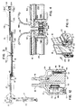
- Fig. 1 is a top perspective view showing two of the bathing door units of this invention in conjunction with a bathing facility;
- Fig. 2 is an exploded perspective view of one of the bathing door units shown in Fig. 1;
- Fig. 3 is a top plan view illustrating the two folding bathing door units positioned as to fully extend the doors to a "closed" position;
- Fig. 4 is an enlarged view in horizontal section illustrating a magnetic lock of the bathing door units in the closed position;
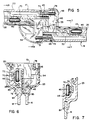
- Fig. 5 is an enlarged detail view illustrating the joint between panels;
- Fig. 6 is sectional view taken along line 6-6 of Fig. 5;
- Fig. 7 is a sectional view taken along line 7-7 of Fig. 5;
- Fig. 8 is an enlarged view, in partial horizontal section illustrating a bistable positionary mechanism for the doors;
- Fig. 9 is a view in vertical section illustrating the mechanism of Fig. 8 in a first position;
- Fig. 10 is a view similar to Fig. 9 illustrating the mechanism in a second position;
- Fig. 11 is an enlarged detail view showing an adjustment feature for the rollers at the bottom of the door; and
- Fig. 12 is a sectional view taken along line 12-12 of Fig. 11.
-
- Referring to Figs. 1 and 3, the bathing door units of this invention are shown generally at 10 and 10A in conjunction with the
bathing facility 12 having atub 13 and ashower head 14. Each of theunits 10 and 10A have the same components with those of unit 10A designed by the same reference numeral followed by the letter "A". The difference is in the orientation of the panels generally 17, 19 and 17A and 19A. This is seen in conjunction with Fig. 3 where thebathing units 10 and 10a are shown in an extended or closed position with respect to thebathing facility 12. - Referring specifically to Fig. 2, it is seen that each of the bathing door units as represented by unit generally 10, is composed of two
panel members panel member 16 being a slidable panel and 18 being a pivotable panel member such as will be better understood as the description proceeds. Panel generally 17 includespanel member 18 as well as atop frame 20 and abottom frame 21. In a similar manner, panel generally 19 also has similar top andbottom frames panel member 16. All of theframes - Positioned along the side of
panel member 18 is apivot column 26 which has a pivot bushing 31 connected thereto at its upper end by thescrew 34.Pivot bushing 31 is adapted to be engaged by the projection 36 of thepivot block 33 which is attached to theexpander jam 29 also by thescrews 34. It should be further noted that attached to the bottom of theexpander jam 29 is apivot block 38 for engagement withpivot bushing 35 which is secured to the bottom of thecolumn 26. This will be more fully explained later in conjunction with Figs. 8-10. Afelt seal 27 is attached to theexpander jam 29 for sealing againstpivot column 26.Expander jam 29 is in turn attached to awall jam 30 by thescrews 34 and theadjustment clamps 32.Wall jam 30 is secured to the wall such as 15 (see Figs. 1 and 3). - As seen in Fig. 2, there are
roller brackets bottom frames panel 17 by means of thescrews 45.Rollers 46 are rotatably mounted on thebrackets tracks 28 ofpanel 19. In a similar manner,roller brackets bottom frames panel 19 by means ofscrews 45 and ride in tracks ofpanel 17 as will be seen later in conjunction with the Fig. 5-7 and Figs. 11 and 12 descriptions.Suitable end caps respective roller brackets frames seals 57. Secured to one end of thepanel member 18, such as by thegroove 41 by a friction fit, is aseal member 39 having aside portion 40 for sealably and slidably engaging the adjacent surface ofpanel member 18 whenpanel member 16 slides thereover. Secured to the other end ofpanel member 16 is ahandle 59 enclosed at opposite ends byend caps 61 and 62. - Referring specifically to Fig. 4, the
handles panel members compartments Magnets handles flexible sections portions slots bathing door units 10 and 10A as also seen in Fig. 3. - Figs. 5-7 illustrate the positioning of the
rollers 46 in the tracks of thepanels bracket members arms 70 to which are attached therollers 46 by means of the shafts of screws 47 (See Fig. 2) which are held in a nonrotatable manner by lock nuts 72. Theseelongated arms 70 are interconnected to thebracket members bracket members top frames slots 78 and intogrooves 79. All of the frame extrusions have slots such as shown at 81 in Figs. 6 and 7 for receiving the panel members such as 16 and 18. The panel members have been secured therein by a suitable adhesive such as Speed Bonder 324 structural adhesive and solventless activator FMD 387 both available from the Loctite Corporation in Newington, Connecticut. - Referring specifically to Fig. 5, there is illustrated the positioning of the
arms 70 and therollers 46 from theirrespective brackets Bracket 51 positions aroller 46 in theroller track 28 oftop frame 20 andbracket 43 positions aroller 46 in theroller track 28 of thetop frame 23. These oppositely positionedroller brackets panel 19 as it is slid away from thepanel 17. This can also be seen in conjunction with Fig. 3. Suitableresilient bumper members brackets rollers 46 from thebrackets panel members respective frames lower brackets top brackets portion 53 is reversed. - Referring to Figs. 8, 9 and 10, these show the lifting mechanism for the
panel member 18 and accordinglypanel member 16. Apivot bushing 35 is attached to thepivot column 26 by thescrew 91 fastened through thehole 84 and intogroove 79. There are opposingholes bushing 35 which accommodatecam pin 82.Cam pin 82 rides over the hill type cam surfaces 87 and 89 ofcam member 85 and rides upwardly thereon until the cam pin rests in the opposinggroves cam pin 82 rests in the lowest portion of the cam surfaces 87 and 88, thepanel members panel member 18 is pivoted, this will cause thecam pin 82 to ride up the cam surfaces 87 and 88 to ultimately rest in the opposinggroves panel member 18 such as indicated in Fig. 10. This raising motion affords a distance between thepanel members tub 13 to afford easy cleaning. As seen in Fig. 8, there is aslot 93 provided in thepivot block 38 to accommodate a lower portion of a leg of theexpander jam 29 andwall jam 30. This affords a stable construction. - Figs. 11 and 12 illustrate the adjustment feature of
lower bracket member 52 androller 46. This is afforded by anadjustment slot 93 extending throughblock portion 92 of thebracket 52 withslot 93accommodating screw 45, which is fastened intoframe 24. Adjustment of the height ofroller 46 againsttrack 28 inframe 21 is effected by looseningscrew 45 and turningadjustment screw 95 in threadedpassage 96. When the desired adjustment is made, screw 45 is retightened. As best seen in Fig. 12, abottom seal 57 is provided having an enlarged head 74 for fitting into undercut 75 offrame member 21 as well asframe member 24. - An important feature in the fabrication of the
bathing door unit 10 is the fact that there is no continuous frame structure surrounding thepanel members panel members top frame 20 andbottom frame 21 andpivot column 26 with respect topanel 18 and top andbottom frames pivot column frames - Yet another important feature is the fact that the
upper frames lower frames hand panel assemblies 10 and 10A.Upper brackets brackets - While preferred embodiments have been described above, it should be readily apparent to those skilled in the art from this disclosure that a number of modifications and changes may be made without departing from the spirit and scope of the invention. For example, in the previous description there was shown a
single roller member 46 supported by thebracket arms 70. It can be appreciated that a multiplicity of roller members could be secured thereto. This would provide even a more easily slidable bath door unit. However, it would be more costly. Further, while a magnetic attraction system is shown in Fig. 4 for closing the opposingpanels units 10 and 10A, the magnetic system could be employed in conjunction with onepanel 19 ofunit 10 and a magnetic strip such as fastened to a wall. - Alternatively, these could be eliminated and still have the advantages of the simplified frame structure and roller system. The same is true with respect to the raising and lowering apparatus shown in Figs. 8, 9 and 10.
Claims (10)
- A pivotal and extendible bathing door unit, comprising a first panel (17) pivotally connected to a supporting wall (15) and a second panel (19) extendibly connected to said first panel, said first and second panels having respectively at their upper end a top frame with a roller track (28), characterized in that it comprises a first roller bracket member (43) and second roller bracket member (51), each bracket member having an elongate arm (70) and a roller (46), the roller (46) being connected to the elongate arm (70), the bracket member (43) of the first roller bracket being connected to the end face of the top frame of the first panel (17), the elongate arm (70) of the first roller bracket extending away from the first panel (17) and adjacent to the roller track (28) of the second panel (19), the roller (46) of the first roller bracket riding in the roller track (28) of the second panel (19), and the bracket member (51) of the second roller bracket being connected to the end face of the top frame of the second panel (19), the elongate arm (70) of the second roller bracket extending away from the second panel (19) and adjacent to the roller track (28) of the first panel (17), the roller (46) of the second roller bracket riding in the roller track (28) of the first panel (17).
- The door unit of claim 1, characterized in that each of the bracket members (43,51) have a resilient bumper (49,50) connected thereto to provide a stop for the second panel (19) as it is slid away from the first panel (17).
- The door unit as defined in claim 1 or 2, characterized in that each panel (17,19) has a bottom frame defining a lower roller track (28), a first lower roller bracket and a second lower roller bracket said lower roller brackets having each a bracket member (44, 52), a vertical leg portion, an elongate arm (70) and a lower roller (46) the bracket member being interconnected to the elongate arm through the vertical leg portion, the roller being mounted on the elongate arm, the bracket member (44,52) of each of the lower roller brackets being connected to the end face of its respective bottom frame, the elongate arm (70) of the first lower roller bracket extending away from the first panel (17) and adjacent to the lower roller track (28) of the second panel (19), the roller (46) of the first lower roller bracket riding in the lower roller track (28) of the second panel (19), and the elongate arm (70) of the second roller bracket extending away from the second panel (19) and adjacent to the lower roller track (28) of the first panel, the roller (46) of the second lower roller bracket riding in the lower roller track (28) of the first panel (17), the bracket members (44,52) of the lower roller brackets being vertically adjustable for vertically positioning said roller (46) of said roller brackets relative to its respective lower track (28).
- The door unit as defined in claim 1, characterized in that said first and second panels are secured to discontinuous frame structures (20,21,26; 23,24,59).
- The door unit as defined in claim 4, characterized in that said frame structure are of a three-sided configuration.
- The door unit of claim 1, further characterized by magnetic means (64) connected to a lateral edge of said second panel (19) opposite said first panel (17) for magnetic attraction to a vertically extending magnetic strip (64A) on a lateral edge of a third laterally extending panel (19A).
- The door unit as defined in claim 6, characterized in that said magnetic means includes a flexible magnetic strip (64) frictionally engaged by a handle portion (59).
- The door unit as defined in claim 1, characterized in that the first panel is pivotally connected to a supporting wall along a vertically extending side support and camming means (85) are connected to a lower end of said side support to provide a lifting action and an intermediate resting position for said first panel upon rotation thereof.
- The door unit of claim 8, characterized in that the camming means includes a raised portion for lifting the door between the two lower portions.
- The door unit of claim 9, characterized in that said camming means includes a pin adapted to ride along the raised portion.
Applications Claiming Priority (3)
| Application Number | Priority Date | Filing Date | Title |
|---|---|---|---|
| US08/087,569 US5417272A (en) | 1993-07-02 | 1993-07-02 | Bathing door unit |
| US87569 | 1993-07-02 | ||
| PCT/US1994/007539 WO1995001119A1 (en) | 1993-07-02 | 1994-06-30 | Bathing door unit |
Publications (2)
| Publication Number | Publication Date |
|---|---|
| EP0706342A1 EP0706342A1 (en) | 1996-04-17 |
| EP0706342B1 true EP0706342B1 (en) | 2000-03-29 |
Family
ID=22205955
Family Applications (1)
| Application Number | Title | Priority Date | Filing Date |
|---|---|---|---|
| EP94922089A Expired - Lifetime EP0706342B1 (en) | 1993-07-02 | 1994-06-30 | Bathing door unit |
Country Status (11)
| Country | Link |
|---|---|
| US (1) | US5417272A (en) |
| EP (1) | EP0706342B1 (en) |
| JP (1) | JP3191876B2 (en) |
| CN (1) | CN1050510C (en) |
| AU (1) | AU694127B2 (en) |
| CA (1) | CA2103650C (en) |
| DE (2) | DE69423759T2 (en) |
| ES (1) | ES2147578T3 (en) |
| PH (1) | PH31273A (en) |
| SG (1) | SG43144A1 (en) |
| WO (1) | WO1995001119A1 (en) |
Cited By (2)
| Publication number | Priority date | Publication date | Assignee | Title |
|---|---|---|---|---|
| EP1160406A2 (en) | 2000-06-03 | 2001-12-05 | KL-Beschläge Karl Loggen GmbH | Hinge with notched supporting surface |
| WO2013063151A1 (en) * | 2011-10-24 | 2013-05-02 | C.R. Laurence Company Inc. | Sliding shower door assembly |
Families Citing this family (40)
| Publication number | Priority date | Publication date | Assignee | Title |
|---|---|---|---|---|
| US5832980A (en) * | 1996-02-16 | 1998-11-10 | Nt Dor-O-Matic Inc. | Floating pivot sliding and swinging panel construction for doors and the like |
| US5893181A (en) * | 1996-10-15 | 1999-04-13 | Moncaster; Thomas R. | Bathing enclosure |
| US5908064A (en) * | 1996-10-30 | 1999-06-01 | Sterling Plumbing Group, Inc. | Bathing door unit |
| DE19700886A1 (en) * | 1997-01-14 | 1998-07-16 | Dorma Gmbh & Co Kg | Shower partition |
| DE29703332U1 (en) * | 1997-02-25 | 1997-04-30 | Lido-Duschabtrennungen Ges.m.b.H. & Co. KG, Taufkirchen | Tub partition |
| USD397414S (en) | 1997-04-02 | 1998-08-25 | Moncaster Thomas R | Bathing enclosure |
| US6068041A (en) * | 1998-08-01 | 2000-05-30 | Herman Miller Inc. | Adjustable partition assembly |
| KR100363036B1 (en) | 1998-09-09 | 2002-12-11 | (주)단건축사사무소 | Sliding door |
| KR20020059941A (en) * | 2001-01-09 | 2002-07-16 | 이기웅 | Door shuter forashower booth |
| US6435253B1 (en) * | 2001-02-28 | 2002-08-20 | Smed International, Inc. | Extendible partition assembly |
| US6618871B2 (en) | 2001-07-24 | 2003-09-16 | Kohler Co. | Shower door assembly |
| DE10212011C1 (en) * | 2002-03-18 | 2003-10-09 | Dorma Gmbh & Co Kg | Sliding element suspended from a running rail by means of idlers |
| US6659155B1 (en) * | 2002-04-05 | 2003-12-09 | Freedom Door Company, Inc. | Bidirectional swinging screen door and frame assembly |
| US6643898B1 (en) | 2002-05-18 | 2003-11-11 | Southeastern Aluminum Products, Inc. | Self-centering pivot door hinge system |
| GB0227920D0 (en) | 2002-11-29 | 2003-01-08 | Esl Healthcare Ltd | Improvements in or relating to shower screens |
| JP4297906B2 (en) * | 2003-05-07 | 2009-07-15 | スガツネ工業株式会社 | Guide device for plate-like objects |
| US7458410B1 (en) * | 2003-11-28 | 2008-12-02 | Dan Bronner | Multiple door joining assembly |
| CN1788665B (en) * | 2004-12-19 | 2010-08-18 | 潘忠勋 | Temperature control type oxygen-filled shower device (room) |
| US20060168894A1 (en) * | 2005-02-01 | 2006-08-03 | Gideon Gorjian | Pre-fabricated sliding door assembly |
| USD531712S1 (en) * | 2005-05-13 | 2006-11-07 | KL-Beschläge Karl Loggen GmbH | Sliding door for shower cubicle |
| US7607199B2 (en) | 2005-06-13 | 2009-10-27 | C.R. Laurence Company, Inc. | Frameless glass door hinge |
| US20070119549A1 (en) * | 2005-11-30 | 2007-05-31 | Weiland William R | Sliding panel interlock |
| US8162414B2 (en) * | 2007-07-20 | 2012-04-24 | Albert Weiss | Door for structure for presenting and displaying goods |
| JP2009131589A (en) * | 2007-11-05 | 2009-06-18 | Okada Soshoku Kanamono Kk | Opening/closing member and partitioning unit using the same |
| KR100989439B1 (en) | 2008-04-25 | 2010-10-28 | 주식회사 베스밸리 | Door Booth Removal System for Glass Booth |
| US8443549B2 (en) * | 2010-03-08 | 2013-05-21 | Stanley Black & Decker, Inc. | Sliding door with large opening |
| CN102261212B (en) * | 2010-05-24 | 2013-06-12 | 苏州科逸住宅设备股份有限公司 | Safety bathroom door |
| US8756864B2 (en) * | 2010-09-17 | 2014-06-24 | Stanley Black & Decker, Inc. | Slide door |
| AU2012253230A1 (en) * | 2011-05-12 | 2013-10-17 | Maliform Pty. Ltd. | Improvements in bathing fixtures |
| DE102013103046A1 (en) * | 2013-03-26 | 2014-10-02 | Dorma Gmbh + Co. Kg | Locking and locking unit for a partition wall system and partition wall system |
| CN203308298U (en) * | 2013-05-13 | 2013-11-27 | 佛山市理想卫浴有限公司 | door assembly |
| SG2013063110A (en) * | 2013-08-20 | 2015-03-30 | Nam Lee Pressed Metal Ind Ltd | A rotatable sliding window |
| CN103654556A (en) * | 2013-11-07 | 2014-03-26 | 安徽省智汇电气技术有限公司 | Multifunctional bathing device |
| US10060168B2 (en) | 2015-01-19 | 2018-08-28 | Kohler Co. | Shower door assemblies |
| KR200485745Y1 (en) * | 2015-07-30 | 2018-02-14 | 강윤구 | Keep Closed The Shower Room Door |
| JP6527473B2 (en) | 2016-01-18 | 2019-06-05 | 株式会社ハイレックスコーポレーション | Opening and closing mechanism |
| ES2972847T3 (en) * | 2017-11-28 | 2024-06-17 | Bortoluzzi Sistemi Spa | Servomechanism for furniture leaf |
| US10837695B2 (en) * | 2017-12-04 | 2020-11-17 | Electrolux Home Products, Inc. | Refrigerator assembly |
| CN109549533B (en) * | 2018-11-09 | 2020-11-13 | 宣城市欧帝斯卫浴有限公司 | Multifunctional arc-shaped shower room |
| US20250237100A1 (en) * | 2023-12-21 | 2025-07-24 | Universal City Studios Llc | Hinge assembly for a gate |
Family Cites Families (26)
| Publication number | Priority date | Publication date | Assignee | Title |
|---|---|---|---|---|
| US2331822A (en) * | 1938-12-06 | 1943-10-12 | Eugene H Zechiel | Folding closure for recess tub shower bath |
| US2723896A (en) * | 1952-02-21 | 1955-11-15 | Gen Motors Corp | Refrigerator door seal |
| US2850089A (en) * | 1954-05-21 | 1958-09-02 | Charles W Burke | Telescopic door |
| US2852816A (en) * | 1958-01-09 | 1958-09-23 | Excel Corp | Driver's sash assembly |
| US3054118A (en) * | 1961-10-30 | 1962-09-18 | James A Bullock | Shower doors |
| US3102581A (en) * | 1961-11-28 | 1963-09-03 | Kinkead Industries | Mounting structure for slidable doors |
| US3188699A (en) * | 1963-05-13 | 1965-06-15 | Herbert J Walters | Pivoting bathtub enclosure |
| US3272257A (en) * | 1964-01-16 | 1966-09-13 | A & D Fabricating Co Inc | Flexible door hinge system |
| DE1926341A1 (en) * | 1969-05-23 | 1970-11-26 | Spiegelglas Und Gussglas Verka | Lockable joint fitting for window or door leaves |
| US3750737A (en) * | 1972-05-01 | 1973-08-07 | R Woodward | Adjustable width folding door |
| US4276919A (en) * | 1977-06-16 | 1981-07-07 | Walters Kenneth I | Enclosure doors |
| US4437266A (en) * | 1980-03-21 | 1984-03-20 | Keller Wilbur L | Weatherstripping kit for sliding windows |
| US4635699A (en) * | 1984-04-06 | 1987-01-13 | Covenant Manufacturing Co. | Retractable safety shield |
| DE3505219C1 (en) * | 1985-02-15 | 1986-05-15 | Günter 3563 Dautphetal Reichel | Shower screen |
| US4619074A (en) * | 1985-08-12 | 1986-10-28 | Leung Ignatius Y P | Convertible door system |
| US4785485A (en) * | 1987-01-20 | 1988-11-22 | Keller Industries | Three panel bath enclosure |
| DE3705433A1 (en) * | 1987-02-20 | 1988-09-08 | Heinz Georg Baus | SHOWER SEPARATION WITH A SWING LEAF |
| US4878530A (en) * | 1987-04-03 | 1989-11-07 | Marielle Jean | Bathroom panel |
| DE3711609A1 (en) * | 1987-04-07 | 1988-10-27 | Heinz Georg Baus | SHOWER SEPARATION |
| US5123129A (en) * | 1988-08-10 | 1992-06-23 | Lyons Donald D | Waterproof hinged panel assembly |
| DE3838591A1 (en) * | 1988-11-15 | 1990-05-23 | Hueppe Gmbh & Co | Sliding door for a shower partition |
| DE3838590C1 (en) * | 1988-11-15 | 1989-11-30 | Hueppe Gmbh & Co, 2903 Bad Zwischenahn, De | Sealing arrangement for a revolving door in shower partitions |
| DE9002749U1 (en) * | 1990-03-06 | 1990-05-10 | Kermi Gmbh, 94447 Plattling | Self-closing door hinge |
| US5097543A (en) * | 1990-12-03 | 1992-03-24 | Waterline Products Co. Ltd. | Shower door |
| DE4205784C2 (en) * | 1991-03-28 | 1994-05-11 | Schulte Duschkabinen | Shower partition with linear extension |
| DE9205399U1 (en) * | 1992-04-18 | 1992-06-17 | Roloff, Heinz-Rudolf, 4150 Krefeld | Hinge fitting for shower cubicle doors |
-
1993
- 1993-07-02 US US08/087,569 patent/US5417272A/en not_active Expired - Lifetime
- 1993-08-05 CA CA002103650A patent/CA2103650C/en not_active Expired - Lifetime
-
1994
- 1994-06-30 DE DE69423759T patent/DE69423759T2/en not_active Expired - Fee Related
- 1994-06-30 SG SG1996004371A patent/SG43144A1/en unknown
- 1994-06-30 AU AU72552/94A patent/AU694127B2/en not_active Ceased
- 1994-06-30 EP EP94922089A patent/EP0706342B1/en not_active Expired - Lifetime
- 1994-06-30 DE DE0706342T patent/DE706342T1/en active Pending
- 1994-06-30 CN CN94193017.3A patent/CN1050510C/en not_active Expired - Lifetime
- 1994-06-30 JP JP50368095A patent/JP3191876B2/en not_active Expired - Fee Related
- 1994-06-30 WO PCT/US1994/007539 patent/WO1995001119A1/en not_active Ceased
- 1994-06-30 ES ES94922089T patent/ES2147578T3/en not_active Expired - Lifetime
- 1994-07-01 PH PH48563A patent/PH31273A/en unknown
Cited By (3)
| Publication number | Priority date | Publication date | Assignee | Title |
|---|---|---|---|---|
| EP1160406A2 (en) | 2000-06-03 | 2001-12-05 | KL-Beschläge Karl Loggen GmbH | Hinge with notched supporting surface |
| EP2284342A2 (en) | 2000-06-03 | 2011-02-16 | KL-Beschläge Karl Loggen GmbH | Hinge with notched supporting surface |
| WO2013063151A1 (en) * | 2011-10-24 | 2013-05-02 | C.R. Laurence Company Inc. | Sliding shower door assembly |
Also Published As
| Publication number | Publication date |
|---|---|
| US5417272A (en) | 1995-05-23 |
| HK1013941A1 (en) | 1999-09-17 |
| SG43144A1 (en) | 1997-10-17 |
| CN1128491A (en) | 1996-08-07 |
| DE69423759D1 (en) | 2000-05-04 |
| DE706342T1 (en) | 1997-04-10 |
| CN1050510C (en) | 2000-03-22 |
| CA2103650A1 (en) | 1995-01-03 |
| DE69423759T2 (en) | 2000-12-14 |
| AU7255294A (en) | 1995-01-24 |
| ES2147578T3 (en) | 2000-09-16 |
| EP0706342A1 (en) | 1996-04-17 |
| AU694127B2 (en) | 1998-07-16 |
| WO1995001119A1 (en) | 1995-01-12 |
| JP3191876B2 (en) | 2001-07-23 |
| CA2103650C (en) | 1998-07-21 |
| JPH08512109A (en) | 1996-12-17 |
| PH31273A (en) | 1998-06-18 |
Similar Documents
| Publication | Publication Date | Title |
|---|---|---|
| EP0706342B1 (en) | Bathing door unit | |
| US5908064A (en) | Bathing door unit | |
| US4276919A (en) | Enclosure doors | |
| CA2242043C (en) | Anti-derailing mechanism for track mounted bath doors | |
| EP3216965B1 (en) | Shower door adjustment device and shower door | |
| US4887394A (en) | Adjustment apparatus for supporting a slidable door | |
| US5690157A (en) | Rigid panel folding shower door assembly having improved horizontal track and method for making the same | |
| HK1013941B (en) | Bathing door unit | |
| US4574526A (en) | Sliding closure | |
| US3260303A (en) | Multi-panel sliding door structure | |
| IE913549A1 (en) | A sliding entry door | |
| TWI775629B (en) | door panel steering | |
| DE59202111D1 (en) | Shower partition. | |
| JPH06229060A (en) | Edge for partition | |
| JP2504630Y2 (en) | Skylight device | |
| WO1996028077A1 (en) | A shower partition | |
| JP2572346Y2 (en) | Folding door | |
| ATE333827T1 (en) | PARTITION FOR A SHOWER | |
| KR20000004670U (en) | Swing and Sliding Rack Doors | |
| JPH10102758A (en) | Closet storage unit | |
| JPH10252342A5 (en) | ||
| JPH0139348Y2 (en) | ||
| CA1280317C (en) | Structure having a movable panel | |
| JPH08303105A (en) | Folding door device | |
| JPS62236986A (en) | Folding door |
Legal Events
| Date | Code | Title | Description |
|---|---|---|---|
| PUAI | Public reference made under article 153(3) epc to a published international application that has entered the european phase |
Free format text: ORIGINAL CODE: 0009012 |
|
| 17P | Request for examination filed |
Effective date: 19960129 |
|
| AK | Designated contracting states |
Kind code of ref document: A1 Designated state(s): BE DE ES FR GB IT NL |
|
| EL | Fr: translation of claims filed | ||
| DET | De: translation of patent claims | ||
| 17Q | First examination report despatched |
Effective date: 19970313 |
|
| GRAG | Despatch of communication of intention to grant |
Free format text: ORIGINAL CODE: EPIDOS AGRA |
|
| GRAG | Despatch of communication of intention to grant |
Free format text: ORIGINAL CODE: EPIDOS AGRA |
|
| GRAH | Despatch of communication of intention to grant a patent |
Free format text: ORIGINAL CODE: EPIDOS IGRA |
|
| GRAH | Despatch of communication of intention to grant a patent |
Free format text: ORIGINAL CODE: EPIDOS IGRA |
|
| GRAA | (expected) grant |
Free format text: ORIGINAL CODE: 0009210 |
|
| RIC1 | Information provided on ipc code assigned before grant |
Free format text: 7A 47K 3/34 A, 7E 05D 15/06 B, 7E 05D 11/10 B |
|
| AK | Designated contracting states |
Kind code of ref document: B1 Designated state(s): BE DE ES FR GB IT NL |
|
| PG25 | Lapsed in a contracting state [announced via postgrant information from national office to epo] |
Ref country code: NL Free format text: LAPSE BECAUSE OF FAILURE TO SUBMIT A TRANSLATION OF THE DESCRIPTION OR TO PAY THE FEE WITHIN THE PRESCRIBED TIME-LIMIT Effective date: 20000329 Ref country code: BE Free format text: LAPSE BECAUSE OF FAILURE TO SUBMIT A TRANSLATION OF THE DESCRIPTION OR TO PAY THE FEE WITHIN THE PRESCRIBED TIME-LIMIT Effective date: 20000329 |
|
| REF | Corresponds to: |
Ref document number: 69423759 Country of ref document: DE Date of ref document: 20000504 |
|
| ITF | It: translation for a ep patent filed | ||
| GRAG | Despatch of communication of intention to grant |
Free format text: ORIGINAL CODE: EPIDOS AGRA |
|
| ET | Fr: translation filed | ||
| RAP2 | Party data changed (patent owner data changed or rights of a patent transferred) |
Owner name: KOHLER CO. |
|
| NLV1 | Nl: lapsed or annulled due to failure to fulfill the requirements of art. 29p and 29m of the patents act | ||
| REG | Reference to a national code |
Ref country code: ES Ref legal event code: FG2A Ref document number: 2147578 Country of ref document: ES Kind code of ref document: T3 |
|
| REG | Reference to a national code |
Ref country code: FR Ref legal event code: TP |
|
| PLBE | No opposition filed within time limit |
Free format text: ORIGINAL CODE: 0009261 |
|
| STAA | Information on the status of an ep patent application or granted ep patent |
Free format text: STATUS: NO OPPOSITION FILED WITHIN TIME LIMIT |
|
| 26N | No opposition filed | ||
| REG | Reference to a national code |
Ref country code: GB Ref legal event code: IF02 |
|
| PGFP | Annual fee paid to national office [announced via postgrant information from national office to epo] |
Ref country code: ES Payment date: 20040625 Year of fee payment: 11 |
|
| PG25 | Lapsed in a contracting state [announced via postgrant information from national office to epo] |
Ref country code: ES Free format text: LAPSE BECAUSE OF NON-PAYMENT OF DUE FEES Effective date: 20050701 |
|
| REG | Reference to a national code |
Ref country code: ES Ref legal event code: FD2A Effective date: 20050701 |
|
| PGFP | Annual fee paid to national office [announced via postgrant information from national office to epo] |
Ref country code: DE Payment date: 20070525 Year of fee payment: 14 |
|
| PGFP | Annual fee paid to national office [announced via postgrant information from national office to epo] |
Ref country code: IT Payment date: 20070614 Year of fee payment: 14 |
|
| PG25 | Lapsed in a contracting state [announced via postgrant information from national office to epo] |
Ref country code: DE Free format text: LAPSE BECAUSE OF NON-PAYMENT OF DUE FEES Effective date: 20090101 |
|
| PG25 | Lapsed in a contracting state [announced via postgrant information from national office to epo] |
Ref country code: IT Free format text: LAPSE BECAUSE OF NON-PAYMENT OF DUE FEES Effective date: 20080630 |
|
| PGFP | Annual fee paid to national office [announced via postgrant information from national office to epo] |
Ref country code: FR Payment date: 20110729 Year of fee payment: 18 |
|
| PGFP | Annual fee paid to national office [announced via postgrant information from national office to epo] |
Ref country code: GB Payment date: 20110721 Year of fee payment: 18 |
|
| GBPC | Gb: european patent ceased through non-payment of renewal fee |
Effective date: 20120630 |
|
| REG | Reference to a national code |
Ref country code: FR Ref legal event code: ST Effective date: 20130228 |
|
| PG25 | Lapsed in a contracting state [announced via postgrant information from national office to epo] |
Ref country code: FR Free format text: LAPSE BECAUSE OF NON-PAYMENT OF DUE FEES Effective date: 20120702 Ref country code: GB Free format text: LAPSE BECAUSE OF NON-PAYMENT OF DUE FEES Effective date: 20120630 |