EP0705982A2 - Fan - Google Patents
Fan Download PDFInfo
- Publication number
- EP0705982A2 EP0705982A2 EP95202642A EP95202642A EP0705982A2 EP 0705982 A2 EP0705982 A2 EP 0705982A2 EP 95202642 A EP95202642 A EP 95202642A EP 95202642 A EP95202642 A EP 95202642A EP 0705982 A2 EP0705982 A2 EP 0705982A2
- Authority
- EP
- European Patent Office
- Prior art keywords
- fan
- cover
- cavity
- housing
- air
- Prior art date
- Legal status (The legal status is an assumption and is not a legal conclusion. Google has not performed a legal analysis and makes no representation as to the accuracy of the status listed.)
- Granted
Links
Images


Classifications
-
- F—MECHANICAL ENGINEERING; LIGHTING; HEATING; WEAPONS; BLASTING
- F04—POSITIVE - DISPLACEMENT MACHINES FOR LIQUIDS; PUMPS FOR LIQUIDS OR ELASTIC FLUIDS
- F04D—NON-POSITIVE-DISPLACEMENT PUMPS
- F04D25/00—Pumping installations or systems
- F04D25/02—Units comprising pumps and their driving means
- F04D25/08—Units comprising pumps and their driving means the working fluid being air, e.g. for ventilation
-
- F—MECHANICAL ENGINEERING; LIGHTING; HEATING; WEAPONS; BLASTING
- F04—POSITIVE - DISPLACEMENT MACHINES FOR LIQUIDS; PUMPS FOR LIQUIDS OR ELASTIC FLUIDS
- F04D—NON-POSITIVE-DISPLACEMENT PUMPS
- F04D29/00—Details, component parts, or accessories
- F04D29/40—Casings; Connections of working fluid
- F04D29/42—Casings; Connections of working fluid for radial or helico-centrifugal pumps
- F04D29/4206—Casings; Connections of working fluid for radial or helico-centrifugal pumps especially adapted for elastic fluid pumps
- F04D29/4226—Fan casings
-
- F—MECHANICAL ENGINEERING; LIGHTING; HEATING; WEAPONS; BLASTING
- F04—POSITIVE - DISPLACEMENT MACHINES FOR LIQUIDS; PUMPS FOR LIQUIDS OR ELASTIC FLUIDS
- F04D—NON-POSITIVE-DISPLACEMENT PUMPS
- F04D29/00—Details, component parts, or accessories
- F04D29/60—Mounting; Assembling; Disassembling
- F04D29/62—Mounting; Assembling; Disassembling of radial or helico-centrifugal pumps
- F04D29/624—Mounting; Assembling; Disassembling of radial or helico-centrifugal pumps especially adapted for elastic fluid pumps
- F04D29/626—Mounting or removal of fans
-
- F—MECHANICAL ENGINEERING; LIGHTING; HEATING; WEAPONS; BLASTING
- F24—HEATING; RANGES; VENTILATING
- F24F—AIR-CONDITIONING; AIR-HUMIDIFICATION; VENTILATION; USE OF AIR CURRENTS FOR SCREENING
- F24F13/00—Details common to, or for air-conditioning, air-humidification, ventilation or use of air currents for screening
- F24F13/20—Casings or covers
- F24F2013/205—Mounting a ventilator fan therein
Definitions
- the invention relates to a fan adapted for use as component of a ventilation system for a building or a part thereof, for example a dwelling.
- a fan adapted for use as component of a ventilation system for a building or a part thereof, for example a dwelling.
- the comparatively heavy motor forms part of the fan during fitting.
- the invention provides a fan of the stated type which has the feature that: the motor directly supports the rotor; the housing has an opening through which the cavity is accessible from outside; the motor is supported by a cover with which the opening can be closed; and the cover can be coupled to the edge of the opening by means of coupling means embodied such that the cover can be coupled without a tool to the opening edge, which coupling means only form part of the edge and the cover, are for instance co-acting screw threads, a bayonet fitting, a snap-coupling.
- An additional advantage of the structure of the invention is that the motor is easily exchangeable, whereby a supplier can provide different motors, i.e. motors of different power, in a standard housing.
- the embodiment which has the feature that the coupling means are embodied such that the cover can only be removed from the edge using a tool, for example a snap-coupling which is accessible from outside with a tool.
- Figures 1, 2, 3, 4, 5, 6, 7 and 10 all relate to a fan 1 which is adapted for use as component of a ventilation system for a dwelling.
- the fan 1 comprises a housing 3 enclosing a cavity 2.
- the fan further comprises a motor 4 which drives for rotation a rotor 6 carrying air displacement blades 5, which blades 5 are accommodated in the cavity 2.
- the fan further comprises three air inlets 7, 8 and 9 which are each adapted for coupling to an air intake conduit 10 (see figure 5) and debouch into cavity 2.
- the fan further comprises an air outlet 11 which is adapted for coupling to an air outlet conduit (not drawn) and connects onto the cavity 2.
- the air inlets 7, 8, 9 lie in one principal plane.
- the air outlet 10 connects onto an outlet duct 16 extending substantially tangentially of the substantially rotation symmetrical cavity.
- Caps 17, 18 and 19 can be used to close two of the associated air inlets 7, 8 and 9 respectively, whereby only one air inlet is used. If required, more than one of the air inlets 7, 8 and 9 can also be used simultaneously.
- the motor 4 directly supports the rotor 6 with the blades 5.
- the housing 3 has an opening 21 through which the cavity 2 is accessible from outside.
- the motor 4 is supported by a cover 22 with which the opening 21 can be closed.
- This cover 22 can be coupled to the edge 23 of opening 21 by means of coupling means embodied such that cover 22 can be coupled to the opening edge 23 without use of a tool.
- coupling means several examples of which will be described hereinbelow, only form part of the edge 23 and the cover 22.
- Figures 1, 2 and 6 relate to an embodiment in which use is made of a snap-coupling.
- Figure 8 relates to the use of co-acting screw threads, while figure 9 shows the use of a bayonet fitting.
- the housing is supported on for instance a wall 29 (see for example figure 3) via a base 30.
- Base 30 fixes the insert 15, which is manufactured from polystyrene foam material, in the housing 3.
- This housing 3 bears on its corner points corner fastening elements 31 each having slotted holes 32 and 33 extending in two mutually perpendicular directions and an elongate support 34 for the electricity cable 20 which can be fixed in the manner shown in figure 10 to the support 34 by means of a screw 35.
- Fastening screws 36 (see figure 10) can be placed through slotted holes 32, 33 to fix the housing 3 on the bearing construction, for instance the wall 29 shown in figure 3.
- a generally cross-shaped structure 37 is formed on the base 30. This serves to prevent whirling in the cavity 2 and is also dimensioned such that it positions the insert 15 correctly in housing 3.
- a base 38 which carries a separate cross 39 of acoustic damping material, for example of mineral fibres.
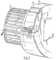
- Figure 7 shows that the motor 4 can be placed in snapping co-action with recesses 42 present in the cover 22 by means of snap-lips 40 with oblique leading surface 41.
- the screw-driver 27 By inserting the screw-driver 27 into the interspace between the peripheral wall 43 of the cover 22 and a snap-lip 40 the coupling between the snap protrusion 44 present thereon and the corresponding recess 42 can be broken whereby the motor 4 with the rotor 6 carrying the blades 5 can be separated from the cover 22, for example for replacement of the motor or for inspection purposes.
- the housing 3 consists preferably of plastic and can be produced with any suitable manufacturing method, for instance injection moulding.
- Figure 5 shows the manner in which an air inlet or outlet conduit can be connected to an air inlet or air outlet.
- the air inlet conduit 10 fits round the zone of the air inlet 7 protruding furthest outward. An air-tight connection is ensured by means of a strip of sealing adhesive tape 45.
- Figure 3 shows that the cable 20 shown in figure 1 and protruding from the peripheral wall 43 of cover 22 extends in the fitted situation of cover 22 between the inner peripheral wall 46 of opening 21 and the outer peripheral wall 43 of cover 22.
- the cable 20 Via a recess 47 the cable 20 is trained outward, where as according to figure 10 it can be connected to support 34 by means of screw 35, being relieved of tension with a clamping strip 48.
- the recess 47 is preferably embodied such that cable 22 fits clampingly therein.
- the interspace between the peripheral walls 43 and 46 is also preferably dimensioned such that cable 20 fits clamping therein with some force.
- the bases 30 and 38 can be coupled to housing 3 with snap lips 49.
- FIGS 8 and 9 show respective fans 49 and 50, whereof the respective covers 51 and 52 are coupled to housings 55 and 56 respectively with a threaded coupling 53 and a bayonet fitting 54.
- the fans 49 and 50 can otherwise have the same structure as described above.
Abstract
the motor directly supports the rotor;
the housing has an opening through which the cavity is accessible from outside;
the motor is supported by a cover with which the opening can be closed; and
the cover can be coupled to the edge of the opening by means of coupling means embodied such that the cover can be coupled without a tool to the opening edge, which coupling means only form part of the edge and the cover, are for instance co-acting screw threads, a bayonet fitting, a snap-coupling.
Description
- The invention relates to a fan adapted for use as component of a ventilation system for a building or a part thereof, for example a dwelling. In the fitting of such a fan, which is normally arranged on a wall by a technician, it is considered a drawback that the comparatively heavy motor forms part of the fan during fitting. In this respect it is a first object of the invention to allow fitting of a fan to take place such that the motor is arranged only after fitting of the fan on the supporting surface.
- In respect of the above the invention provides a fan of the stated type which has the feature that:
the motor directly supports the rotor;
the housing has an opening through which the cavity is accessible from outside;
the motor is supported by a cover with which the opening can be closed; and
the cover can be coupled to the edge of the opening by means of coupling means embodied such that the cover can be coupled without a tool to the opening edge, which coupling means only form part of the edge and the cover, are for instance co-acting screw threads, a bayonet fitting, a snap-coupling. - An additional advantage of the structure of the invention is that the motor is easily exchangeable, whereby a supplier can provide different motors, i.e. motors of different power, in a standard housing.
- In order to avoid a cover with motor being too easy to remove, the embodiment is recommended which has the feature that the coupling means are embodied such that the cover can only be removed from the edge using a tool, for example a snap-coupling which is accessible from outside with a tool.
- Claims 3-18 give advantageous embodiments.
- The invention will now be elucidated with reference to the accompanying drawings of a number of embodiments, to which the invention is not limited. In the drawings:
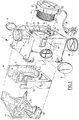
- figure 1 shows a partly broken away exploded view of a fan according to the invention;
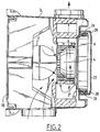
- figure 2 shows a longitudinal section of the assembled fan;
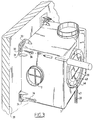
- figure 3 is a perspective view of the fan during fitting of the housing;
- figure 4 shows a detail;
- figure 5 shows a partly broken away perspective view in which is shown the coupling between the fan and a feed or discharge pipe for air;
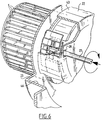
- figure 6 shows a partly broken away perspective view of a part of the fan in which is shown the releasable coupling to the housing of the motor carrying the cover;
- figure 7 shows a partly broken away perspective view of a part of the fan in which is shown the releasable coupling between the cover and the motor;
- figure 8 is a partly broken away perspective view of another embodiment;
- figure 9 is a view corresponding with figure 8 of yet another embodiment;
- figure 10 is a partly broken away perspective view of a corner support to which is fixed an electricity cable; and
- figure 11 shows a perspective view of an insert alternatively arranged in the fan housing.
- Figures 1, 2, 3, 4, 5, 6, 7 and 10 all relate to a fan 1 which is adapted for use as component of a ventilation system for a dwelling. The fan 1 comprises a
housing 3 enclosing a cavity 2. The fan further comprises a motor 4 which drives for rotation a rotor 6 carryingair displacement blades 5, whichblades 5 are accommodated in the cavity 2. The fan further comprises three air inlets 7, 8 and 9 which are each adapted for coupling to an air intake conduit 10 (see figure 5) and debouch into cavity 2. The fan further comprises anair outlet 11 which is adapted for coupling to an air outlet conduit (not drawn) and connects onto the cavity 2. As shown in figure 1, the air inlets 7, 8, 9 lie in one principal plane. They join ontorecesses 12, 13, 14 respectively in aninsert 15 which is made from foam plastic and which also bounds the cavity 2. Theair outlet 10 connects onto anoutlet duct 16 extending substantially tangentially of the substantially rotation symmetrical cavity.Caps electrical cable 20 the rotor 6 is set into rotation such that air is drawn in from at least one air inlet 7, 8, 9 and blown out via theair outlet 11. - The motor 4 directly supports the rotor 6 with the
blades 5. Thehousing 3 has an opening 21 through which the cavity 2 is accessible from outside. The motor 4 is supported by acover 22 with which the opening 21 can be closed. Thiscover 22 can be coupled to theedge 23 of opening 21 by means of coupling means embodied such thatcover 22 can be coupled to theopening edge 23 without use of a tool. These coupling means, several examples of which will be described hereinbelow, only form part of theedge 23 and thecover 22. Figures 1, 2 and 6 relate to an embodiment in which use is made of a snap-coupling. Figure 8 relates to the use of co-acting screw threads, while figure 9 shows the use of a bayonet fitting. - Standing
lips 24 withholes 25 are present on theedge 23. These are placed in snapping co-action withprotrusions 26 present oncover 22. As shown in figure 6, after the snapping connection has been performed, thecover 22 can be removed fromhousing 3 by inserting for instance a screw-driver 27 inholes 28, whereby thelips 24 can be moved outward so that they disengage from theprotrusions 26. For coupling of thecover 22 it can suffice to press thecover 22 carrying the motor 4 axially onto the correct position. A snapping coupling then takes place due to the oblique leading edge ofprotrusions 26 drawn in figure 2. - In this way is achieved that, after the housing has been fixed to a bearing construction, the motor can be placed without the use of a tool. A tool is however required in order to remove the motor.
- The housing is supported on for instance a wall 29 (see for example figure 3) via a
base 30.Base 30 fixes theinsert 15, which is manufactured from polystyrene foam material, in thehousing 3. Thishousing 3 bears on its corner pointscorner fastening elements 31 each having slottedholes elongate support 34 for theelectricity cable 20 which can be fixed in the manner shown in figure 10 to thesupport 34 by means of ascrew 35. Fastening screws 36 (see figure 10) can be placed through slottedholes housing 3 on the bearing construction, for instance thewall 29 shown in figure 3. - A generally
cross-shaped structure 37 is formed on thebase 30. This serves to prevent whirling in the cavity 2 and is also dimensioned such that it positions theinsert 15 correctly inhousing 3. In order to obtain an improved damping of noise resulting from turbulence, use can be made as according to figure 11 of abase 38 which carries aseparate cross 39 of acoustic damping material, for example of mineral fibres. - Figure 7 shows that the motor 4 can be placed in snapping co-action with recesses 42 present in the
cover 22 by means of snap-lips 40 with oblique leadingsurface 41. By inserting the screw-driver 27 into the interspace between theperipheral wall 43 of thecover 22 and a snap-lip 40 the coupling between thesnap protrusion 44 present thereon and the corresponding recess 42 can be broken whereby the motor 4 with the rotor 6 carrying theblades 5 can be separated from thecover 22, for example for replacement of the motor or for inspection purposes. - The
housing 3 consists preferably of plastic and can be produced with any suitable manufacturing method, for instance injection moulding. - Figure 5 shows the manner in which an air inlet or outlet conduit can be connected to an air inlet or air outlet. In the example shown in figure 5 the air inlet conduit 10 fits round the zone of the air inlet 7 protruding furthest outward. An air-tight connection is ensured by means of a strip of sealing
adhesive tape 45. - Figure 3 shows that the
cable 20 shown in figure 1 and protruding from theperipheral wall 43 ofcover 22 extends in the fitted situation ofcover 22 between the innerperipheral wall 46 of opening 21 and the outerperipheral wall 43 ofcover 22. Via arecess 47 thecable 20 is trained outward, where as according to figure 10 it can be connected to support 34 by means ofscrew 35, being relieved of tension with aclamping strip 48. Therecess 47 is preferably embodied such thatcable 22 fits clampingly therein. The interspace between theperipheral walls cable 20 fits clamping therein with some force. - The
bases housing 3 withsnap lips 49. - Figures 8 and 9 show
respective fans housings 55 and 56 respectively with a threadedcoupling 53 and abayonet fitting 54. Thefans
Claims (17)
a housing enclosing a cavity;
a motor which drives for rotation a rotor carrying air displacement blades, which blades are accommodated in the cavity;
at least one air inlet which is adapted for coupling to an air intake conduit and debouches into the cavity; an air outlet which is adapted for coupling to an air outlet conduit and connects onto the cavity;
this such that during operation of the motor the blades displace air from the air inlet to the air outlet;
characterized in that
the motor directly supports the rotor;
the housing has an opening through which the cavity is accessible from outside;
the motor is supported by a cover with which the opening can be closed; and
the cover can be coupled to the edge of the opening by means of coupling means embodied such that the cover can be coupled without a tool to the opening edge, which coupling means only form part of the edge and the cover, are for instance co-acting screw threads, a bayonet fitting, a snap-coupling.
Applications Claiming Priority (2)
| Application Number | Priority Date | Filing Date | Title |
|---|---|---|---|
| NL9401608 | 1994-09-30 | ||
| NL9401608 | 1994-09-30 |
Publications (3)
| Publication Number | Publication Date |
|---|---|
| EP0705982A2 true EP0705982A2 (en) | 1996-04-10 |
| EP0705982A3 EP0705982A3 (en) | 1997-04-09 |
| EP0705982B1 EP0705982B1 (en) | 2001-05-30 |
Family
ID=19864720
Family Applications (1)
| Application Number | Title | Priority Date | Filing Date |
|---|---|---|---|
| EP95202642A Expired - Lifetime EP0705982B1 (en) | 1994-09-30 | 1995-10-02 | Fan |
Country Status (7)
| Country | Link |
|---|---|
| EP (1) | EP0705982B1 (en) |
| AT (1) | ATE201750T1 (en) |
| DE (1) | DE69521096T2 (en) |
| DK (1) | DK0705982T3 (en) |
| ES (1) | ES2158038T3 (en) |
| GR (1) | GR3036413T3 (en) |
| PT (1) | PT705982E (en) |
Cited By (4)
| Publication number | Priority date | Publication date | Assignee | Title |
|---|---|---|---|---|
| EP0805542A2 (en) * | 1996-05-02 | 1997-11-05 | MAICO ELEKTROAPPARATE-FABRIK GmbH | Fan motor |
| EP0964161A3 (en) * | 1998-06-12 | 2001-04-04 | Bitron S.p.A. | Fan rotor |
| FR2801940A1 (en) * | 1999-12-06 | 2001-06-08 | Valeo Climatisation | HEATING AND / OR AIR CONDITIONING SYSTEM WITH A MOTOR SUPPORT MOUNTED ON A PULSE BOX |
| CN102251977A (en) * | 2011-08-24 | 2011-11-23 | 张家港施亿百机电设备有限公司 | External tilting centrifugal fan |
Citations (6)
| Publication number | Priority date | Publication date | Assignee | Title |
|---|---|---|---|---|
| DE1428225A1 (en) * | 1963-06-20 | 1969-07-10 | Rotron Mfg Company Inc | Centrifugal blower |
| US3537544A (en) * | 1968-06-11 | 1970-11-03 | Emerson Electric Co | Sound absorbing grille |
| FR2271425A1 (en) * | 1974-05-17 | 1975-12-12 | Fimec | Centrifugal fan of cheap construction - has drum housing for motor and rotor and end caps with central partition |
| DE8626016U1 (en) * | 1986-09-30 | 1986-11-06 | Süddeutsche Kühlerfabrik Julius Fr. Behr GmbH & Co KG, 7000 Stuttgart | Bracket for holding a fan in a housing |
| US4950133A (en) * | 1988-11-15 | 1990-08-21 | Alopex Industries, Inc. | Air blower assembly |
| DE4321924C1 (en) * | 1993-07-01 | 1994-06-23 | Siegenia Frank Kg | Radial-flow fan production method |
-
1995
- 1995-10-02 EP EP95202642A patent/EP0705982B1/en not_active Expired - Lifetime
- 1995-10-02 DE DE69521096T patent/DE69521096T2/en not_active Expired - Fee Related
- 1995-10-02 DK DK95202642T patent/DK0705982T3/en active
- 1995-10-02 PT PT95202642T patent/PT705982E/en unknown
- 1995-10-02 ES ES95202642T patent/ES2158038T3/en not_active Expired - Lifetime
- 1995-10-02 AT AT95202642T patent/ATE201750T1/en not_active IP Right Cessation
-
2001
- 2001-08-20 GR GR20010401264T patent/GR3036413T3/en not_active IP Right Cessation
Patent Citations (6)
| Publication number | Priority date | Publication date | Assignee | Title |
|---|---|---|---|---|
| DE1428225A1 (en) * | 1963-06-20 | 1969-07-10 | Rotron Mfg Company Inc | Centrifugal blower |
| US3537544A (en) * | 1968-06-11 | 1970-11-03 | Emerson Electric Co | Sound absorbing grille |
| FR2271425A1 (en) * | 1974-05-17 | 1975-12-12 | Fimec | Centrifugal fan of cheap construction - has drum housing for motor and rotor and end caps with central partition |
| DE8626016U1 (en) * | 1986-09-30 | 1986-11-06 | Süddeutsche Kühlerfabrik Julius Fr. Behr GmbH & Co KG, 7000 Stuttgart | Bracket for holding a fan in a housing |
| US4950133A (en) * | 1988-11-15 | 1990-08-21 | Alopex Industries, Inc. | Air blower assembly |
| DE4321924C1 (en) * | 1993-07-01 | 1994-06-23 | Siegenia Frank Kg | Radial-flow fan production method |
Non-Patent Citations (1)
| Title |
|---|
| STORK AIR: "Woonhuisventilatoren, type CML (brochure ZAL-80-0594-018748)" May 1994 , J.E.STORK VENTILATOREN B.V. , ZWOLLE-NL XP002024546 * the whole document * * |
Cited By (8)
| Publication number | Priority date | Publication date | Assignee | Title |
|---|---|---|---|---|
| EP0805542A2 (en) * | 1996-05-02 | 1997-11-05 | MAICO ELEKTROAPPARATE-FABRIK GmbH | Fan motor |
| EP0805542A3 (en) * | 1996-05-02 | 2000-07-05 | MAICO ELEKTROAPPARATE-FABRIK GmbH | Fan motor |
| EP0964161A3 (en) * | 1998-06-12 | 2001-04-04 | Bitron S.p.A. | Fan rotor |
| FR2801940A1 (en) * | 1999-12-06 | 2001-06-08 | Valeo Climatisation | HEATING AND / OR AIR CONDITIONING SYSTEM WITH A MOTOR SUPPORT MOUNTED ON A PULSE BOX |
| EP1106834A1 (en) * | 1999-12-06 | 2001-06-13 | Valeo Climatisation | Motor mounting on fan casing |
| JP2001211597A (en) * | 1999-12-06 | 2001-08-03 | Valeo Climatisation | Heater or air conditioner having electric motor support member attached to blower housing |
| CN102251977A (en) * | 2011-08-24 | 2011-11-23 | 张家港施亿百机电设备有限公司 | External tilting centrifugal fan |
| CN102251977B (en) * | 2011-08-24 | 2013-01-16 | 张家港施亿百机电设备有限公司 | External tilting centrifugal fan |
Also Published As
| Publication number | Publication date |
|---|---|
| EP0705982A3 (en) | 1997-04-09 |
| EP0705982B1 (en) | 2001-05-30 |
| DE69521096D1 (en) | 2001-07-05 |
| PT705982E (en) | 2001-10-30 |
| GR3036413T3 (en) | 2001-11-30 |
| DE69521096T2 (en) | 2002-05-02 |
| ES2158038T3 (en) | 2001-09-01 |
| DK0705982T3 (en) | 2001-07-30 |
| ATE201750T1 (en) | 2001-06-15 |
Similar Documents
| Publication | Publication Date | Title |
|---|---|---|
| US4867640A (en) | Exhaust fan for bathrooms and the like | |
| US5879232A (en) | Exhaust fan | |
| KR100238512B1 (en) | Air conditioner for ceiling | |
| US20190101125A1 (en) | Ventilation system and method | |
| WO2004042894A3 (en) | Electric motor assembly | |
| US6076370A (en) | Snap fit filter for an air conditioner | |
| EP0705982A2 (en) | Fan | |
| US6032478A (en) | Air conditioner outdoor section construction | |
| KR100271458B1 (en) | Compressor mounting arrangement | |
| KR100296892B1 (en) | Air conditioner indoor section construction | |
| KR100264871B1 (en) | Motor attaching device of airconditioner | |
| KR100322221B1 (en) | Capacitor cover | |
| KR100353776B1 (en) | Combination room air/split air conditioner | |
| KR20030046486A (en) | Air Conditioner | |
| US5548868A (en) | Pilot and detent apparatus for a vacuum device | |
| KR100710089B1 (en) | Ceiling embedded-type air conditioning apparatus | |
| US10598397B2 (en) | Ventilation fan | |
| US6379241B1 (en) | Wind-hole device of a ventilator for an air conditioner | |
| JPH08320141A (en) | Ventilation fan for duct | |
| CN219300974U (en) | Knock-out hole assembly of air conditioner shell | |
| JPS6222376B2 (en) | ||
| JPS6222375B2 (en) | ||
| JPS5837436A (en) | Ventilating device | |
| JPH0326899A (en) | Air feeding device | |
| JPS6342168B2 (en) |
Legal Events
| Date | Code | Title | Description |
|---|---|---|---|
| PUAI | Public reference made under article 153(3) epc to a published international application that has entered the european phase |
Free format text: ORIGINAL CODE: 0009012 |
|
| AK | Designated contracting states |
Kind code of ref document: A2 Designated state(s): AT BE CH DE DK ES FR GB GR IE IT LI LU MC NL PT SE |
|
| PUAL | Search report despatched |
Free format text: ORIGINAL CODE: 0009013 |
|
| AK | Designated contracting states |
Kind code of ref document: A3 Designated state(s): AT BE CH DE DK ES FR GB GR IE IT LI LU MC NL PT SE |
|
| 17P | Request for examination filed |
Effective date: 19971008 |
|
| 17Q | First examination report despatched |
Effective date: 19971202 |
|
| GRAG | Despatch of communication of intention to grant |
Free format text: ORIGINAL CODE: EPIDOS AGRA |
|
| GRAG | Despatch of communication of intention to grant |
Free format text: ORIGINAL CODE: EPIDOS AGRA |
|
| GRAH | Despatch of communication of intention to grant a patent |
Free format text: ORIGINAL CODE: EPIDOS IGRA |
|
| GRAH | Despatch of communication of intention to grant a patent |
Free format text: ORIGINAL CODE: EPIDOS IGRA |
|
| GRAA | (expected) grant |
Free format text: ORIGINAL CODE: 0009210 |
|
| AK | Designated contracting states |
Kind code of ref document: B1 Designated state(s): AT BE CH DE DK ES FR GB GR IE IT LI LU MC NL PT SE |
|
| REF | Corresponds to: |
Ref document number: 201750 Country of ref document: AT Date of ref document: 20010615 Kind code of ref document: T |
|
| REG | Reference to a national code |
Ref country code: CH Ref legal event code: EP |
|
| ITF | It: translation for a ep patent filed |
Owner name: STUDIO INGG. FISCHETTI & WEBER |
|
| REF | Corresponds to: |
Ref document number: 69521096 Country of ref document: DE Date of ref document: 20010705 |
|
| REG | Reference to a national code |
Ref country code: IE Ref legal event code: FG4D |
|
| REG | Reference to a national code |
Ref country code: DK Ref legal event code: T3 |
|
| REG | Reference to a national code |
Ref country code: ES Ref legal event code: FG2A Ref document number: 2158038 Country of ref document: ES Kind code of ref document: T3 |
|
| REG | Reference to a national code |
Ref country code: CH Ref legal event code: NV Representative=s name: ARNOLD & SIEDSMA AG |
|
| ET | Fr: translation filed | ||
| REG | Reference to a national code |
Ref country code: GB Ref legal event code: IF02 |
|
| PLBE | No opposition filed within time limit |
Free format text: ORIGINAL CODE: 0009261 |
|
| STAA | Information on the status of an ep patent application or granted ep patent |
Free format text: STATUS: NO OPPOSITION FILED WITHIN TIME LIMIT |
|
| 26N | No opposition filed | ||
| PGFP | Annual fee paid to national office [announced via postgrant information from national office to epo] |
Ref country code: MC Payment date: 20021028 Year of fee payment: 8 |
|
| PGFP | Annual fee paid to national office [announced via postgrant information from national office to epo] |
Ref country code: LU Payment date: 20021029 Year of fee payment: 8 Ref country code: AT Payment date: 20021029 Year of fee payment: 8 |
|
| PGFP | Annual fee paid to national office [announced via postgrant information from national office to epo] |
Ref country code: FR Payment date: 20021030 Year of fee payment: 8 Ref country code: DE Payment date: 20021030 Year of fee payment: 8 Ref country code: BE Payment date: 20021030 Year of fee payment: 8 |
|
| PGFP | Annual fee paid to national office [announced via postgrant information from national office to epo] |
Ref country code: SE Payment date: 20021031 Year of fee payment: 8 Ref country code: NL Payment date: 20021031 Year of fee payment: 8 Ref country code: GR Payment date: 20021031 Year of fee payment: 8 Ref country code: ES Payment date: 20021031 Year of fee payment: 8 Ref country code: DK Payment date: 20021031 Year of fee payment: 8 Ref country code: CH Payment date: 20021031 Year of fee payment: 8 |
|
| PGFP | Annual fee paid to national office [announced via postgrant information from national office to epo] |
Ref country code: PT Payment date: 20030930 Year of fee payment: 9 |
|
| PG25 | Lapsed in a contracting state [announced via postgrant information from national office to epo] |
Ref country code: LU Free format text: LAPSE BECAUSE OF NON-PAYMENT OF DUE FEES Effective date: 20031002 Ref country code: AT Free format text: LAPSE BECAUSE OF NON-PAYMENT OF DUE FEES Effective date: 20031002 |
|
| PG25 | Lapsed in a contracting state [announced via postgrant information from national office to epo] |
Ref country code: SE Free format text: LAPSE BECAUSE OF NON-PAYMENT OF DUE FEES Effective date: 20031003 Ref country code: ES Free format text: LAPSE BECAUSE OF NON-PAYMENT OF DUE FEES Effective date: 20031003 |
|
| PGFP | Annual fee paid to national office [announced via postgrant information from national office to epo] |
Ref country code: GB Payment date: 20031003 Year of fee payment: 9 |
|
| PGFP | Annual fee paid to national office [announced via postgrant information from national office to epo] |
Ref country code: IE Payment date: 20031007 Year of fee payment: 9 |
|
| PG25 | Lapsed in a contracting state [announced via postgrant information from national office to epo] |
Ref country code: MC Free format text: LAPSE BECAUSE OF NON-PAYMENT OF DUE FEES Effective date: 20031031 Ref country code: LI Free format text: LAPSE BECAUSE OF NON-PAYMENT OF DUE FEES Effective date: 20031031 Ref country code: CH Free format text: LAPSE BECAUSE OF NON-PAYMENT OF DUE FEES Effective date: 20031031 Ref country code: BE Free format text: LAPSE BECAUSE OF NON-PAYMENT OF DUE FEES Effective date: 20031031 |
|
| BERE | Be: lapsed |
Owner name: J.E. *STORK VENTILATOREN B.V. Effective date: 20031031 |
|
| PG25 | Lapsed in a contracting state [announced via postgrant information from national office to epo] |
Ref country code: DK Free format text: LAPSE BECAUSE OF NON-PAYMENT OF DUE FEES Effective date: 20040430 |
|
| PG25 | Lapsed in a contracting state [announced via postgrant information from national office to epo] |
Ref country code: NL Free format text: LAPSE BECAUSE OF NON-PAYMENT OF DUE FEES Effective date: 20040501 Ref country code: DE Free format text: LAPSE BECAUSE OF NON-PAYMENT OF DUE FEES Effective date: 20040501 |
|
| PG25 | Lapsed in a contracting state [announced via postgrant information from national office to epo] |
Ref country code: GR Free format text: LAPSE BECAUSE OF NON-PAYMENT OF DUE FEES Effective date: 20040504 |
|
| EUG | Se: european patent has lapsed | ||
| REG | Reference to a national code |
Ref country code: DK Ref legal event code: EBP |
|
| REG | Reference to a national code |
Ref country code: CH Ref legal event code: PL |
|
| PG25 | Lapsed in a contracting state [announced via postgrant information from national office to epo] |
Ref country code: FR Free format text: LAPSE BECAUSE OF NON-PAYMENT OF DUE FEES Effective date: 20040630 |
|
| NLV4 | Nl: lapsed or anulled due to non-payment of the annual fee |
Effective date: 20040501 |
|
| REG | Reference to a national code |
Ref country code: FR Ref legal event code: ST |
|
| PG25 | Lapsed in a contracting state [announced via postgrant information from national office to epo] |
Ref country code: GB Free format text: LAPSE BECAUSE OF NON-PAYMENT OF DUE FEES Effective date: 20041002 |
|
| PG25 | Lapsed in a contracting state [announced via postgrant information from national office to epo] |
Ref country code: IE Free format text: LAPSE BECAUSE OF NON-PAYMENT OF DUE FEES Effective date: 20041004 |
|
| REG | Reference to a national code |
Ref country code: ES Ref legal event code: FD2A Effective date: 20031003 |
|
| PG25 | Lapsed in a contracting state [announced via postgrant information from national office to epo] |
Ref country code: PT Free format text: LAPSE BECAUSE OF NON-PAYMENT OF DUE FEES Effective date: 20050404 |
|
| GBPC | Gb: european patent ceased through non-payment of renewal fee |
Effective date: 20041002 |
|
| REG | Reference to a national code |
Ref country code: IE Ref legal event code: MM4A |
|
| REG | Reference to a national code |
Ref country code: PT Ref legal event code: MM4A Free format text: LAPSE DUE TO NON-PAYMENT OF FEES Effective date: 20050404 |
|
| PG25 | Lapsed in a contracting state [announced via postgrant information from national office to epo] |
Ref country code: IT Free format text: LAPSE BECAUSE OF NON-PAYMENT OF DUE FEES;WARNING: LAPSES OF ITALIAN PATENTS WITH EFFECTIVE DATE BEFORE 2007 MAY HAVE OCCURRED AT ANY TIME BEFORE 2007. THE CORRECT EFFECTIVE DATE MAY BE DIFFERENT FROM THE ONE RECORDED. Effective date: 20051002 |