EP0703705B1 - A method for interpolation of a video picture - Google Patents
A method for interpolation of a video picture Download PDFInfo
- Publication number
- EP0703705B1 EP0703705B1 EP95113425A EP95113425A EP0703705B1 EP 0703705 B1 EP0703705 B1 EP 0703705B1 EP 95113425 A EP95113425 A EP 95113425A EP 95113425 A EP95113425 A EP 95113425A EP 0703705 B1 EP0703705 B1 EP 0703705B1
- Authority
- EP
- European Patent Office
- Prior art keywords
- interpolation
- sample
- sample value
- interpolated
- video picture
- Prior art date
- Legal status (The legal status is an assumption and is not a legal conclusion. Google has not performed a legal analysis and makes no representation as to the accuracy of the status listed.)
- Expired - Lifetime
Links
- 238000000034 method Methods 0.000 title claims description 82
- 238000001914 filtration Methods 0.000 claims description 28
- 238000012360 testing method Methods 0.000 claims description 10
- 230000003044 adaptive effect Effects 0.000 description 12
- 230000002123 temporal effect Effects 0.000 description 3
- 238000012935 Averaging Methods 0.000 description 1
- 230000000386 athletic effect Effects 0.000 description 1
- 230000001419 dependent effect Effects 0.000 description 1
- 238000001514 detection method Methods 0.000 description 1
- 230000002708 enhancing effect Effects 0.000 description 1
- 238000005259 measurement Methods 0.000 description 1
- 238000012544 monitoring process Methods 0.000 description 1
Images

Classifications
-
- H—ELECTRICITY
- H04—ELECTRIC COMMUNICATION TECHNIQUE
- H04N—PICTORIAL COMMUNICATION, e.g. TELEVISION
- H04N7/00—Television systems
- H04N7/01—Conversion of standards, e.g. involving analogue television standards or digital television standards processed at pixel level
- H04N7/0117—Conversion of standards, e.g. involving analogue television standards or digital television standards processed at pixel level involving conversion of the spatial resolution of the incoming video signal
- H04N7/012—Conversion between an interlaced and a progressive signal
Definitions
- the present invention relates to a method for interpolation of a video picture.
- the video picture presented as digital sample values is enhanced by adding new sample values, which are formed from the existing sample values with some interpolation method.
- the invention particularly relates to an adaptive and primarily non-linear interpolation method.
- the interpolation of a video picture is applied to television in particular.
- the video signal of the current television standards is interlaced, which means that the video picture consists of two alternating fields, one of which contains the odd number lines and the other the even lines.
- the field frequency is 50 or 60 Hz.
- the interlacing and the low field frequency cause clearly visible errors in the television picture.
- the most typical errors are line flicker and line drift.
- Line flicker can be seen at the frequency of 25 Hz in a picture with a field frequency of 50 Hz, and it occurs at horizontal, light and sharp edges.
- Line drift can occur when the picture has a slowly moving, light and sharp line, which is almost horizontal or slightly bent.
- interpolation methods by which the line frequency is typically doubled, whereby the picture can be shown progressively, for example, so that all lines of the picture are shown at a frequency of 50 Hz.
- the interpolation methods for calculating new samples from the existing samples can be roughly divided into linear and non-linear methods.
- the samples to be added are calculated with some fixed, linear formula, for example as an average value, from the neighboring samples.
- Non-linear methods include median filtering and various adaptive methods, in which the algorithm used in interpolation can vary.
- a disadvantage of the linear methods is their tendency to blur the details of the picture, and their implementation is often rather expensive. On the other hand, they operate reliably on the whole frequency band for which they are intended, i.e. the folding of the signal is minimal.
- a disadvantage of the non-linear methods is the folds produced, which are generally very visible.
- the advantages of the said methods include simple implementation and the sharpness of the picture produced. In this connection, folding means that the method produces signal components which the signal did not have originally.
- Linear methods have also been combined with non-linear methods.
- One example is EP 0 391 094 A2.
- This document describes a method and interpolator for digital interpolation of a pixel, wherein a quincunx sub-sampled digital video signal is converted to an orthogonally sampled signal, signals representative of the pixels neighboring the pixel to be interpolated being taken via delay means to the inputs of a linear filter and combined therein, weighted in a predetermined manner.
- a non-linear filter in which, on the one hand, the output signal of the linear filter and, on the other hand, some of the said signals representative of the pixels neighboring the pixel are combined, the output signal of the non-linear filter represents the pixel to be interpolated.
- Median filtering which this patent application primarily refers to, means that at a certain window, samples of the current or previous field around the sample to be added are selected as the input of the median filter, and the output is the median of these selected sample values, which becomes the value of the sample to be added.
- the filtering is either 3-point, 5-point or 7-point filtering. If the sample pixels are selected vertically or, correspondingly, in the direction of the diameter, the method is called vertical or diagonal filtering, respectively.
- the object of the present invention is to provide an adaptive and non-linear method for interpolation of a video picture.
- the first method is developed by Philips and known as ALFRED (Adaptive Line Flicker Reduction). It uses two interpolation algorithms, vertical linear averaging and vertical 3-point median filtering. The use of the algorithms is controlled so that median filtering, which is the primary method, is not used when strong signal components occur in the frequency band in which its use can result in folding.
- the principle of the method is to monitor the energy of signal components in the critical frequency band, and in accordance with this to change the interpolation algorithm when necessary.
- the use of only vertical filtering causes serration in the inclined edges of the picture.
- Another disadvantage is the fact that switching between the linear and the non-linear filter is not simple, and it easily causes more errors in the picture than using only one filter.
- DDMF Direction Dependent Median Filtering
- the principle of the method is that before deciding which direction is used in median filtering, the close environment of the sample is measured with the purpose of indicating the direction of the edge possibly occurring in it.
- the direction of interpolation is selected on the basis of the measurement made. In other words, the environment is studied first, and then it is decided which method of filtering will be applied.
- Such an adaptive method is e.g. described in EP0 391 094 A2, a video pixel interpolator generates interpolation pixels from incoming picture image pixels for use within a television picture scan line doubler system.
- the interpolator includes a temporal median filter for generating an interpolation pixel by selection of the median one of a plurality of temporal pixel samples derived from incoming video, an intra-field averager means for generating an intra-field pixel average, and a switch connected to switch an input to a line doubler of the system between outputs of the temporal median filter and the intra-field averager in response to detection of pixel motion within the picture image.
- the object of the invention is to provide an adaptive interpolation method, by which the disadvantages of the above prior art adaptive methods are avoided, which is based on a simple principle, and by which an interpolation result with a high quality and as faultless as possible is achieved.
- the adaptive method for interpolation of a video picture in accordance to the invention is defined in claim 1.
- the primary filtering is non-linear interpolation with a relatively large window, for example 7-point median filtering.
- this method gives a high-quality interpolation result, which nevertheless has clear errors particularly at vertical edges. Therefore, the method of the invention also uses an alternative interpolation method, in this embodiment 3-point vertical median filtering, which is applied in cases where the primary filtering gives a poor result.
- a simple test is applied to the result of the primary filtering with regard to the samples of the environment. If the test shows that the result differs too much from the environment, the sample value in question will be with the alternative interpolation method, which is selected so that it efficiently corrects the errors that are likely to occur with the primary method.
- Figure 1 shows the most commonly used 3*3 pixel window, in which the sample value I(n,m,t) of the current field (field t) to be added in the middle of the window is determined.
- the letter n indicates the location of the sample on the line
- m indicates the number of the line
- t indicates that the current field is in question.
- the input of the median filter can consist of sample values of the current field t on the upper line m- I and on the lower line m +1 at points n -1, n and n +1, and the sample value of the previous field t -1 on line m at point n.
- the input includes all these sample values, in 5-point filtering, the values at point n on the upper and lower line are omitted, and 3-point filtering includes, in addition to the sample value of the previous field in the middle, one sample value on the upper and one on the lower line in any direction.
- the so called 9-point median filtering is obtained from the 7-point filtering by weighting the samples to be included or their average value in some suitable way.
- the 7-point and 5-point and the vertical 3-point median filtering are shown mathematically as follows: where I(n,m,t) is the value of the sample at location n on line m of field t.
- the interpolation result obtained is usually good, but these filters have a tendency to fold the signal at high horizontal and diagonal frequencies. As a result, folds or errors occur particularly at the vertical edges of the picture.
- the method according to the invention primarily uses the interpolation method which usually gives a good interpolation result.
- the method is 7-point median filtering, but each sample value produced by interpolation is tested against its environment. If the test shows that the sample value differs from the environment too much, an alternative method, which is particularly suited to correct errors that are likely to occur, is used, that is to say, 3-point vertical median filtering in the primary embodiment.
- the interpolated sample value obtained is tested by calculating vertically the absolute difference signal, which measures the difference of the interpolated sample value from the environment determined by the sample values above and below.
- the primary embodiment of the invention is presented mathematically as follows:
- the threshold value thr used was 8. Using this value, the folds that occurred after the primary interpolation could be efficiently removed by means of the adaptive interpolation.
- both the primary and the secondary interpolation method and the test used for testing the sample value obtained with the primary interpolation method against the surrounding values can vary in many ways.
- the sample value obtained by means of the primary interpolation method which is recommended as generally giving a good result of interpolation, is tested by determining whether it differs more than is allowed from the surrounding sample values, and if so, an alternative interpolation method is used, the alternative method being preferably a method which efficiently corrects the errors that are likely to occur when the primary method is used.
- an alternative interpolation method is used, the alternative method being preferably a method which efficiently corrects the errors that are likely to occur when the primary method is used.
- the interpolation result obtained by means of the alternative method is further tested against the environment, and if the test result so requires, another alternative method of interpolation is used, or, on the basis of testing the output from the primary method, one of the alternative methods is chosen.
- the invention can vary within the scope defined by the attached claims.
Landscapes
- Engineering & Computer Science (AREA)
- Computer Graphics (AREA)
- Multimedia (AREA)
- Signal Processing (AREA)
- Television Systems (AREA)
- Image Processing (AREA)
Description
- The present invention relates to a method for interpolation of a video picture. In this method, the video picture presented as digital sample values is enhanced by adding new sample values, which are formed from the existing sample values with some interpolation method. The invention particularly relates to an adaptive and primarily non-linear interpolation method.
- The interpolation of a video picture is applied to television in particular. The video signal of the current television standards is interlaced, which means that the video picture consists of two alternating fields, one of which contains the odd number lines and the other the even lines. The field frequency is 50 or 60 Hz. The interlacing and the low field frequency cause clearly visible errors in the television picture. The most typical errors are line flicker and line drift. Line flicker can be seen at the frequency of 25 Hz in a picture with a field frequency of 50 Hz, and it occurs at horizontal, light and sharp edges. Line drift can occur when the picture has a slowly moving, light and sharp line, which is almost horizontal or slightly bent. Due to the interlacing, the line is cut into segments, because the part which is covered by the field to be scanned is shown light and the part which was covered by the previous field is shown darker. The result is that the segments seem to "drift" in the direction of the edge line. This phenomenon can be seen clearly in televised athletic contests, for example, where the track lines seem to be running together with the runners. A third typical error is field flicker, which occurs when the field is mostly light, whereby the intensity of the field to be scanned is distinct from the previous field. This is seen in such a way that the whole picture flickers at a frequency of 25 Hz. In addition to the said errors, a line raster can be seen on the screen when it is viewed from a short distance.
- Many enhancing or upward converting methods have been developed to eliminate the said errors. These are interpolation methods by which the line frequency is typically doubled, whereby the picture can be shown progressively, for example, so that all lines of the picture are shown at a frequency of 50 Hz. The interpolation methods for calculating new samples from the existing samples can be roughly divided into linear and non-linear methods. In the linear methods, the samples to be added are calculated with some fixed, linear formula, for example as an average value, from the neighboring samples. Non-linear methods include median filtering and various adaptive methods, in which the algorithm used in interpolation can vary.
- A disadvantage of the linear methods is their tendency to blur the details of the picture, and their implementation is often rather expensive. On the other hand, they operate reliably on the whole frequency band for which they are intended, i.e. the folding of the signal is minimal. A disadvantage of the non-linear methods is the folds produced, which are generally very visible. On the other hand, the advantages of the said methods include simple implementation and the sharpness of the picture produced. In this connection, folding means that the method produces signal components which the signal did not have originally. Linear methods have also been combined with non-linear methods. One example is EP 0 391 094 A2. This document describes a method and interpolator for digital interpolation of a pixel, wherein a quincunx sub-sampled digital video signal is converted to an orthogonally sampled signal, signals representative of the pixels neighboring the pixel to be interpolated being taken via delay means to the inputs of a linear filter and combined therein, weighted in a predetermined manner. At a point after the linear filter, a non-linear filter in which, on the one hand, the output signal of the linear filter and, on the other hand, some of the said signals representative of the pixels neighboring the pixel are combined, the output signal of the non-linear filter represents the pixel to be interpolated.
- Median filtering, which this patent application primarily refers to, means that at a certain window, samples of the current or previous field around the sample to be added are selected as the input of the median filter, and the output is the median of these selected sample values, which becomes the value of the sample to be added. According to the number of samples taken as the input of the median filter, the filtering is either 3-point, 5-point or 7-point filtering. If the sample pixels are selected vertically or, correspondingly, in the direction of the diameter, the method is called vertical or diagonal filtering, respectively. On one hand, the larger the interpolation window used in median filtering is, the more the quality of the interpolation result varies within the picture or between pictures, that is to say that the interpolation can either succeed very well or well, but it can also fail and produce clear errors in the picture. If, on the other hand, the interpolation window is small, i.e. only a small number of adjacent samples are used for the interpolation, the result is more even quality, which means that the interpolation is usually not very good but not very poor, either.
- As was stated earlier, the object of the present invention is to provide an adaptive and non-linear method for interpolation of a video picture. In the following, two known, adaptive interpolation methods are studied briefly as prior art examples. The first method is developed by Philips and known as ALFRED (Adaptive Line Flicker Reduction). It uses two interpolation algorithms, vertical linear averaging and vertical 3-point median filtering. The use of the algorithms is controlled so that median filtering, which is the primary method, is not used when strong signal components occur in the frequency band in which its use can result in folding. The principle of the method is to monitor the energy of signal components in the critical frequency band, and in accordance with this to change the interpolation algorithm when necessary. As one disadvantage of this method, the use of only vertical filtering causes serration in the inclined edges of the picture. Another disadvantage is the fact that switching between the linear and the non-linear filter is not simple, and it easily causes more errors in the picture than using only one filter.
- Another known adaptive method is DDMF (Direction Dependent Median Filtering). The principle of the method is that before deciding which direction is used in median filtering, the close environment of the sample is measured with the purpose of indicating the direction of the edge possibly occurring in it. The direction of interpolation is selected on the basis of the measurement made. In other words, the environment is studied first, and then it is decided which method of filtering will be applied. Such an adaptive method is e.g. described in EP0 391 094 A2, a video pixel interpolator generates interpolation pixels from incoming picture image pixels for use within a television picture scan line doubler system. The interpolator includes a temporal median filter for generating an interpolation pixel by selection of the median one of a plurality of temporal pixel samples derived from incoming video, an intra-field averager means for generating an intra-field pixel average, and a switch connected to switch an input to a line doubler of the system between outputs of the temporal median filter and the intra-field averager in response to detection of pixel motion within the picture image. An advantage of this method compared to ALFRED is the fact that, in principle, inclined edges can be straightened and they can generally be produced without serration. Although the principle of the method is simple, its use requires, especially with high-frequency signal components, a lot of monitoring and testing to avoid selecting the wrong direction of interpolation after all, in which case the errors are very clear. The implementation of the method in practice is thus very complicated.
- The object of the invention is to provide an adaptive interpolation method, by which the disadvantages of the above prior art adaptive methods are avoided, which is based on a simple principle, and by which an interpolation result with a high quality and as faultless as possible is achieved. In order to accomplish this, the adaptive method for interpolation of a video picture in accordance to the invention is defined in
claim 1. - In the embodiment of the invention, which is regarded as the best, the primary filtering is non-linear interpolation with a relatively large window, for example 7-point median filtering. In most cases, this method gives a high-quality interpolation result, which nevertheless has clear errors particularly at vertical edges. Therefore, the method of the invention also uses an alternative interpolation method, in this embodiment 3-point vertical median filtering, which is applied in cases where the primary filtering gives a poor result. A simple test is applied to the result of the primary filtering with regard to the samples of the environment. If the test shows that the result differs too much from the environment, the sample value in question will be with the alternative interpolation method, which is selected so that it efficiently corrects the errors that are likely to occur with the primary method.
- The invention and particularly one embodiment thereof which is regarded as the best will be described below in greater detail with reference to the accompanying Figure 1, showing the window used in median filtering.
- Figure 1 shows the most commonly used 3*3 pixel window, in which the sample value I(n,m,t) of the current field (field t) to be added in the middle of the window is determined. The letter n indicates the location of the sample on the line, m indicates the number of the line and t indicates that the current field is in question. In the most commonly used methods, the input of the median filter can consist of sample values of the current field t on the upper line m-I and on the lower line m+1 at points n-1, n and n+1, and the sample value of the previous field t-1 on line m at point n. In 7-point median filtering, the input includes all these sample values, in 5-point filtering, the values at point n on the upper and lower line are omitted, and 3-point filtering includes, in addition to the sample value of the previous field in the middle, one sample value on the upper and one on the lower line in any direction. The so called 9-point median filtering is obtained from the 7-point filtering by weighting the samples to be included or their average value in some suitable way.
- The 7-point and 5-point and the vertical 3-point median filtering are shown mathematically as follows:

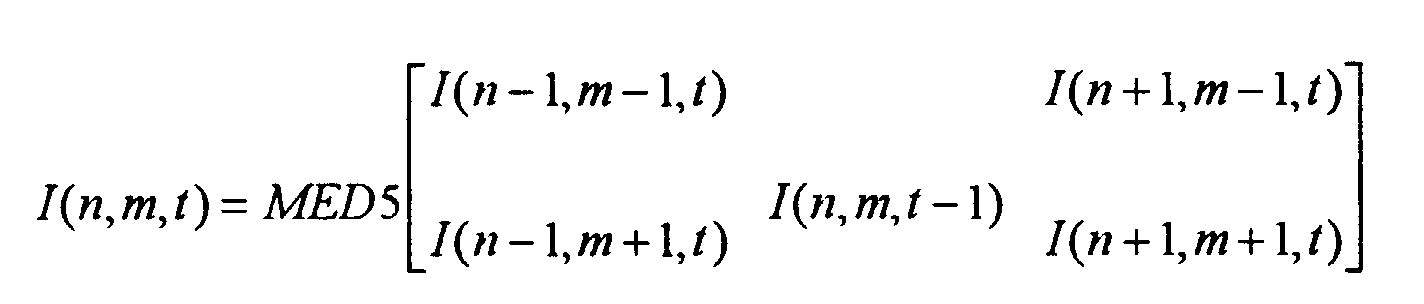 where I(n,m,t) is the value of the sample at location n on line m of field t.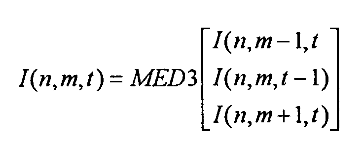
- If a large-window filter is used, with 7 or 5 pixels, for example, the interpolation result obtained is usually good, but these filters have a tendency to fold the signal at high horizontal and diagonal frequencies. As a result, folds or errors occur particularly at the vertical edges of the picture. In spite of this, the method according to the invention primarily uses the interpolation method which usually gives a good interpolation result. In the embodiment that is regarded as the best at present, the method is 7-point median filtering, but each sample value produced by interpolation is tested against its environment. If the test shows that the sample value differs from the environment too much, an alternative method, which is particularly suited to correct errors that are likely to occur, is used, that is to say, 3-point vertical median filtering in the primary embodiment.
- In the embodiment regarded as the best, the interpolated sample value obtained is tested by calculating vertically the absolute difference signal, which measures the difference of the interpolated sample value from the environment determined by the sample values above and below. The primary embodiment of the invention is presented mathematically as follows:

- If now abs(I(n,m-1,t) - I(n,m,t)) - abs(I(n,m-1,t) - I(n,m+1,t)) > thr, thenotherwise I(n,m,t) = I(n,m,t),

where thr is the threshold value set for the difference signal. - When the method according to the primary embodiment of the invention was tested on a video signal having 8-bit samples, the threshold value thr used was 8. Using this value, the folds that occurred after the primary interpolation could be efficiently removed by means of the adaptive interpolation.
- A detailed description of an embodiment of the invention which is regarded as the best has been given above, but a person skilled in the art will understand that in an adaptive method for interpolation of a video picture, both the primary and the secondary interpolation method and the test used for testing the sample value obtained with the primary interpolation method against the surrounding values can vary in many ways.
- In the method of the invention, it is essential that the sample value obtained by means of the primary interpolation method, which is recommended as generally giving a good result of interpolation, is tested by determining whether it differs more than is allowed from the surrounding sample values, and if so, an alternative interpolation method is used, the alternative method being preferably a method which efficiently corrects the errors that are likely to occur when the primary method is used. A skilled person will also understand that in principle there can be more than one alternative methods, in which case the interpolation result obtained by means of the alternative method is further tested against the environment, and if the test result so requires, another alternative method of interpolation is used, or, on the basis of testing the output from the primary method, one of the alternative methods is chosen. The invention can vary within the scope defined by the attached claims.
Claims (7)
- A method for interpolation of a video picture in order to define a sample value for each sample to be interpolated from the values of samples that are either spatially or temporally close to it, comprising a first interpolation method and a second interpolation method, characterized in thata sample value for each sample to be interpolated is defined by means of the first interpolation method,the differences between a thus interpolated sample value from selected surrounding values are calculated andthe interpolated output sample value is replaced by a sample value defined by means of the second interpolation method, if one of the differences exceeds a set limit.
- A method for interpolation of a video picture according to claim 1, characterized in that at least one of the first and the second interpolation methods is a non-linear method.
- A method for interpolation of a video picture according to claim 1 or 2, characterized in thatthe first interpolation method is non-linear and determines the sample value from more than three samples close to it spatially or temporally,the second interpolation method has been chosen so that it replaces the interpolated sample value obtained by means of the first interpolation method by a sample value which has differences to the test environment formed by selected close samples below the set limit.
- A method for interpolation of a video picture according to claim 3, characterized in thatthe first interpolation method is 7-point median filtering,the environment used for calculating difference values is formed by the simultaneous vertically closest sample above and the vertically closest sample below andthe second interpolation method is vertical, 3-point median filtering.
- A method for interpolation of a video picture according to one of the above claims, characterized in that the differences of the interpolated output sample value from the environment formed by selected close samples is calculated by defining the absolute difference signal abs(I(n,m-1t) - I(n,m,t)) -abs(I(n,m-1,t) - I(n,m+1,t)) and comparing it to the set threshold value, whereby I(n,m,t) is the interpolated sample value determined by means of the first interpolation method, I(n,m-1,t) is the simultaneous, vertically closest sample above the sample to be interpolated, and I(n,m+1,t) is the simultaneous, vertically closest sample below the sample to be interpolated.
- A method for interpolation of a video picture according to claim 5, characterized in that the set threshold value is 8, when the sample value is determined by 8 bits.
- A method according to any of the preceding claims, characterized in that alsothe differences of the interpolated output sample value and the environment formed by selected close samples is again calculated andthe output sample value is replaced by a sample value determined by an interpolation method used together with this testing, different from the first and the second method, if the difference exceeds the set limit.
Applications Claiming Priority (2)
| Application Number | Priority Date | Filing Date | Title |
|---|---|---|---|
| FI944353 | 1994-09-20 | ||
| FI944353A FI98590C (en) | 1994-09-20 | 1994-09-20 | Method for interpolating video image |
Publications (3)
| Publication Number | Publication Date |
|---|---|
| EP0703705A2 EP0703705A2 (en) | 1996-03-27 |
| EP0703705A3 EP0703705A3 (en) | 1996-07-24 |
| EP0703705B1 true EP0703705B1 (en) | 1999-12-01 |
Family
ID=8541402
Family Applications (1)
| Application Number | Title | Priority Date | Filing Date |
|---|---|---|---|
| EP95113425A Expired - Lifetime EP0703705B1 (en) | 1994-09-20 | 1995-08-26 | A method for interpolation of a video picture |
Country Status (3)
| Country | Link |
|---|---|
| EP (1) | EP0703705B1 (en) |
| DE (1) | DE69513606T2 (en) |
| FI (1) | FI98590C (en) |
Families Citing this family (3)
| Publication number | Priority date | Publication date | Assignee | Title |
|---|---|---|---|---|
| JP2000308021A (en) * | 1999-04-20 | 2000-11-02 | Niigata Seimitsu Kk | Image processing circuit |
| KR100731523B1 (en) * | 1999-05-25 | 2007-06-25 | 코닌클리케 필립스 일렉트로닉스 엔.브이. | Conversion of Interlaced Video Signals into Progressive Scanned Video Signals |
| JP5029112B2 (en) * | 2007-04-13 | 2012-09-19 | ソニー株式会社 | Image processing apparatus, image processing method, and program |
Family Cites Families (3)
| Publication number | Priority date | Publication date | Assignee | Title |
|---|---|---|---|---|
| US4989090A (en) * | 1989-04-05 | 1991-01-29 | Yves C. Faroudja | Television scan line doubler including temporal median filter |
| FI88091C (en) * | 1990-09-25 | 1993-03-25 | Salora Oy | Method and apparatus for digital interpolation of a pixel |
| DE4211955A1 (en) * | 1992-04-09 | 1993-10-14 | Thomson Brandt Gmbh | Method and device for an interlace progressive conversion |
-
1994
- 1994-09-20 FI FI944353A patent/FI98590C/en active
-
1995
- 1995-08-26 DE DE69513606T patent/DE69513606T2/en not_active Expired - Fee Related
- 1995-08-26 EP EP95113425A patent/EP0703705B1/en not_active Expired - Lifetime
Also Published As
| Publication number | Publication date |
|---|---|
| FI944353A0 (en) | 1994-09-20 |
| EP0703705A2 (en) | 1996-03-27 |
| FI98590B (en) | 1997-03-27 |
| FI944353L (en) | 1996-03-21 |
| DE69513606T2 (en) | 2000-06-21 |
| EP0703705A3 (en) | 1996-07-24 |
| FI98590C (en) | 1997-07-10 |
| DE69513606D1 (en) | 2000-01-05 |
Similar Documents
| Publication | Publication Date | Title |
|---|---|---|
| US7423691B2 (en) | Method of low latency interlace to progressive video format conversion | |
| EP1223748B1 (en) | Motion detection in an interlaced video signal | |
| US6262773B1 (en) | System for conversion of interlaced video to progressive video using edge correlation | |
| KR100327396B1 (en) | Deinterlacing method based on edge-directional intra-field interpolation | |
| US6118488A (en) | Method and apparatus for adaptive edge-based scan line interpolation using 1-D pixel array motion detection | |
| JP4145351B2 (en) | Video signal scanning conversion method, apparatus, and video signal display apparatus | |
| US7206027B2 (en) | Spatial resolution of video images | |
| US6104755A (en) | Motion detection using field-difference measurements | |
| US7227897B2 (en) | Motion vector detector and motion vector detecting method | |
| US20050129306A1 (en) | Method and apparatus for image deinterlacing using neural networks | |
| KR100403364B1 (en) | Apparatus and method for deinterlace of video signal | |
| US10440318B2 (en) | Motion adaptive de-interlacing and advanced film mode detection | |
| KR20040009967A (en) | Apparatus and method for deinterlacing | |
| EP0438507A1 (en) | METHOD AND DEVICE FOR IMPROVING THE VERTICAL RESOLUTION OF A TELEVISION SIGNAL BY SCAN TRANSFORMING. | |
| KR20010026089A (en) | Deinterlacing method based on motion-compensated inter-field interpolation | |
| EP1679886B1 (en) | Method of edge based pixel location and interpolation | |
| US6452972B1 (en) | Motion detection using field-difference measurements | |
| EP0687105B1 (en) | A method for detecting motion in a video signal | |
| EP0703705A2 (en) | A method for interpolation of a video picture | |
| EP0517385B1 (en) | A method of doubling the number of lines of a video signal received in the form of sequential samples | |
| US20060268179A1 (en) | Motion detector for a video display system | |
| EP0536717A2 (en) | A method to double the sample density of an orthogonally sampled picture | |
| KR100931142B1 (en) | Deinterlacing apparatus and method | |
| EP0474285A1 (en) | Edge direction detector for image processing video systems | |
| JPH04227181A (en) | Edge detector |
Legal Events
| Date | Code | Title | Description |
|---|---|---|---|
| PUAI | Public reference made under article 153(3) epc to a published international application that has entered the european phase |
Free format text: ORIGINAL CODE: 0009012 |
|
| AK | Designated contracting states |
Kind code of ref document: A2 Designated state(s): DE FR GB IT |
|
| PUAL | Search report despatched |
Free format text: ORIGINAL CODE: 0009013 |
|
| AK | Designated contracting states |
Kind code of ref document: A3 Designated state(s): DE FR GB IT |
|
| 17P | Request for examination filed |
Effective date: 19960813 |
|
| 17Q | First examination report despatched |
Effective date: 19990127 |
|
| GRAG | Despatch of communication of intention to grant |
Free format text: ORIGINAL CODE: EPIDOS AGRA |
|
| GRAG | Despatch of communication of intention to grant |
Free format text: ORIGINAL CODE: EPIDOS AGRA |
|
| GRAH | Despatch of communication of intention to grant a patent |
Free format text: ORIGINAL CODE: EPIDOS IGRA |
|
| GRAH | Despatch of communication of intention to grant a patent |
Free format text: ORIGINAL CODE: EPIDOS IGRA |
|
| GRAA | (expected) grant |
Free format text: ORIGINAL CODE: 0009210 |
|
| AK | Designated contracting states |
Kind code of ref document: B1 Designated state(s): DE FR GB IT |
|
| ITF | It: translation for a ep patent filed | ||
| REF | Corresponds to: |
Ref document number: 69513606 Country of ref document: DE Date of ref document: 20000105 |
|
| ET | Fr: translation filed | ||
| PLBE | No opposition filed within time limit |
Free format text: ORIGINAL CODE: 0009261 |
|
| STAA | Information on the status of an ep patent application or granted ep patent |
Free format text: STATUS: NO OPPOSITION FILED WITHIN TIME LIMIT |
|
| 26N | No opposition filed | ||
| REG | Reference to a national code |
Ref country code: GB Ref legal event code: IF02 |
|
| PGFP | Annual fee paid to national office [announced via postgrant information from national office to epo] |
Ref country code: FR Payment date: 20050809 Year of fee payment: 11 |
|
| PGFP | Annual fee paid to national office [announced via postgrant information from national office to epo] |
Ref country code: DE Payment date: 20050818 Year of fee payment: 11 |
|
| PGFP | Annual fee paid to national office [announced via postgrant information from national office to epo] |
Ref country code: GB Payment date: 20050824 Year of fee payment: 11 |
|
| PGFP | Annual fee paid to national office [announced via postgrant information from national office to epo] |
Ref country code: IT Payment date: 20060831 Year of fee payment: 12 |
|
| PG25 | Lapsed in a contracting state [announced via postgrant information from national office to epo] |
Ref country code: DE Free format text: LAPSE BECAUSE OF NON-PAYMENT OF DUE FEES Effective date: 20070301 |
|
| GBPC | Gb: european patent ceased through non-payment of renewal fee |
Effective date: 20060826 |
|
| REG | Reference to a national code |
Ref country code: FR Ref legal event code: ST Effective date: 20070430 |
|
| PG25 | Lapsed in a contracting state [announced via postgrant information from national office to epo] |
Ref country code: GB Free format text: LAPSE BECAUSE OF NON-PAYMENT OF DUE FEES Effective date: 20060826 |
|
| PG25 | Lapsed in a contracting state [announced via postgrant information from national office to epo] |
Ref country code: FR Free format text: LAPSE BECAUSE OF NON-PAYMENT OF DUE FEES Effective date: 20060831 |
|
| PG25 | Lapsed in a contracting state [announced via postgrant information from national office to epo] |
Ref country code: IT Free format text: LAPSE BECAUSE OF NON-PAYMENT OF DUE FEES Effective date: 20070826 |