EP0703401B1 - Panel unit swing mechanism - Google Patents
Panel unit swing mechanism Download PDFInfo
- Publication number
- EP0703401B1 EP0703401B1 EP95112980A EP95112980A EP0703401B1 EP 0703401 B1 EP0703401 B1 EP 0703401B1 EP 95112980 A EP95112980 A EP 95112980A EP 95112980 A EP95112980 A EP 95112980A EP 0703401 B1 EP0703401 B1 EP 0703401B1
- Authority
- EP
- European Patent Office
- Prior art keywords
- panel unit
- unit
- guide groove
- case
- swing mechanism
- Prior art date
- Legal status (The legal status is an assumption and is not a legal conclusion. Google has not performed a legal analysis and makes no representation as to the accuracy of the status listed.)
- Expired - Lifetime
Links
Images





Classifications
-
- G—PHYSICS
- G06—COMPUTING OR CALCULATING; COUNTING
- G06F—ELECTRIC DIGITAL DATA PROCESSING
- G06F1/00—Details not covered by groups G06F3/00 - G06F13/00 and G06F21/00
- G06F1/16—Constructional details or arrangements
-
- G—PHYSICS
- G06—COMPUTING OR CALCULATING; COUNTING
- G06F—ELECTRIC DIGITAL DATA PROCESSING
- G06F1/00—Details not covered by groups G06F3/00 - G06F13/00 and G06F21/00
- G06F1/16—Constructional details or arrangements
- G06F1/1613—Constructional details or arrangements for portable computers
- G06F1/1615—Constructional details or arrangements for portable computers with several enclosures having relative motions, each enclosure supporting at least one I/O or computing function
- G06F1/1616—Constructional details or arrangements for portable computers with several enclosures having relative motions, each enclosure supporting at least one I/O or computing function with folding flat displays, e.g. laptop computers or notebooks having a clamshell configuration, with body parts pivoting to an open position around an axis parallel to the plane they define in closed position
-
- F—MECHANICAL ENGINEERING; LIGHTING; HEATING; WEAPONS; BLASTING
- F16—ENGINEERING ELEMENTS AND UNITS; GENERAL MEASURES FOR PRODUCING AND MAINTAINING EFFECTIVE FUNCTIONING OF MACHINES OR INSTALLATIONS; THERMAL INSULATION IN GENERAL
- F16M—FRAMES, CASINGS OR BEDS OF ENGINES, MACHINES OR APPARATUS, NOT SPECIFIC TO ENGINES, MACHINES OR APPARATUS PROVIDED FOR ELSEWHERE; STANDS; SUPPORTS
- F16M11/00—Stands or trestles as supports for apparatus or articles placed thereon ; Stands for scientific apparatus such as gravitational force meters
- F16M11/02—Heads
- F16M11/04—Means for attachment of apparatus; Means allowing adjustment of the apparatus relatively to the stand
- F16M11/06—Means for attachment of apparatus; Means allowing adjustment of the apparatus relatively to the stand allowing pivoting
- F16M11/10—Means for attachment of apparatus; Means allowing adjustment of the apparatus relatively to the stand allowing pivoting around a horizontal axis
- F16M11/105—Means for attachment of apparatus; Means allowing adjustment of the apparatus relatively to the stand allowing pivoting around a horizontal axis the horizontal axis being the roll axis, e.g. for creating a landscape-portrait rotation
-
- F—MECHANICAL ENGINEERING; LIGHTING; HEATING; WEAPONS; BLASTING
- F16—ENGINEERING ELEMENTS AND UNITS; GENERAL MEASURES FOR PRODUCING AND MAINTAINING EFFECTIVE FUNCTIONING OF MACHINES OR INSTALLATIONS; THERMAL INSULATION IN GENERAL
- F16M—FRAMES, CASINGS OR BEDS OF ENGINES, MACHINES OR APPARATUS, NOT SPECIFIC TO ENGINES, MACHINES OR APPARATUS PROVIDED FOR ELSEWHERE; STANDS; SUPPORTS
- F16M11/00—Stands or trestles as supports for apparatus or articles placed thereon ; Stands for scientific apparatus such as gravitational force meters
- F16M11/20—Undercarriages with or without wheels
- F16M11/2007—Undercarriages with or without wheels comprising means allowing pivoting adjustment
- F16M11/2021—Undercarriages with or without wheels comprising means allowing pivoting adjustment around a horizontal axis
-
- G—PHYSICS
- G06—COMPUTING OR CALCULATING; COUNTING
- G06F—ELECTRIC DIGITAL DATA PROCESSING
- G06F1/00—Details not covered by groups G06F3/00 - G06F13/00 and G06F21/00
- G06F1/16—Constructional details or arrangements
- G06F1/1613—Constructional details or arrangements for portable computers
- G06F1/1615—Constructional details or arrangements for portable computers with several enclosures having relative motions, each enclosure supporting at least one I/O or computing function
- G06F1/1622—Constructional details or arrangements for portable computers with several enclosures having relative motions, each enclosure supporting at least one I/O or computing function with enclosures rotating around an axis perpendicular to the plane they define or with ball-joint coupling, e.g. PDA with display enclosure orientation changeable between portrait and landscape by rotation with respect to a coplanar body enclosure
-
- G—PHYSICS
- G06—COMPUTING OR CALCULATING; COUNTING
- G06F—ELECTRIC DIGITAL DATA PROCESSING
- G06F1/00—Details not covered by groups G06F3/00 - G06F13/00 and G06F21/00
- G06F1/16—Constructional details or arrangements
- G06F1/1613—Constructional details or arrangements for portable computers
- G06F1/1633—Constructional details or arrangements of portable computers not specific to the type of enclosures covered by groups G06F1/1615 - G06F1/1626
- G06F1/1637—Details related to the display arrangement, including those related to the mounting of the display in the housing
-
- G—PHYSICS
- G06—COMPUTING OR CALCULATING; COUNTING
- G06F—ELECTRIC DIGITAL DATA PROCESSING
- G06F2200/00—Indexing scheme relating to G06F1/04 - G06F1/32
- G06F2200/16—Indexing scheme relating to G06F1/16 - G06F1/18
- G06F2200/161—Indexing scheme relating to constructional details of the monitor
- G06F2200/1614—Image rotation following screen orientation, e.g. switching from landscape to portrait mode
-
- Y—GENERAL TAGGING OF NEW TECHNOLOGICAL DEVELOPMENTS; GENERAL TAGGING OF CROSS-SECTIONAL TECHNOLOGIES SPANNING OVER SEVERAL SECTIONS OF THE IPC; TECHNICAL SUBJECTS COVERED BY FORMER USPC CROSS-REFERENCE ART COLLECTIONS [XRACs] AND DIGESTS
- Y10—TECHNICAL SUBJECTS COVERED BY FORMER USPC
- Y10S—TECHNICAL SUBJECTS COVERED BY FORMER USPC CROSS-REFERENCE ART COLLECTIONS [XRACs] AND DIGESTS
- Y10S248/00—Supports
- Y10S248/917—Video display screen support
- Y10S248/919—Adjustably orientable video screen support
-
- Y—GENERAL TAGGING OF NEW TECHNOLOGICAL DEVELOPMENTS; GENERAL TAGGING OF CROSS-SECTIONAL TECHNOLOGIES SPANNING OVER SEVERAL SECTIONS OF THE IPC; TECHNICAL SUBJECTS COVERED BY FORMER USPC CROSS-REFERENCE ART COLLECTIONS [XRACs] AND DIGESTS
- Y10—TECHNICAL SUBJECTS COVERED BY FORMER USPC
- Y10S—TECHNICAL SUBJECTS COVERED BY FORMER USPC CROSS-REFERENCE ART COLLECTIONS [XRACs] AND DIGESTS
- Y10S248/00—Supports
- Y10S248/917—Video display screen support
- Y10S248/919—Adjustably orientable video screen support
- Y10S248/922—Angular
Definitions
- the invention relates to a mechanism for swinging a panel unit according to the first portion of claim 1.
- a key input section is arranged in the top of a unit case, a display case is swingably attached to the unit case to freely close the key input section, and a display section is arranged in that face of the display case which is opposed to the key input section.
- the key input section is made longer in the horizontal direction, considering the arrangement of keys at the key input section. Therefore, the display case which covers the key input section is also made longer in the horizontal direction and the display section is thus made longer in the same direction.
- the display case is swung and erected relative to the unit case, therefore, the display section is always kept longer in the horizontal direction.
- This display section which is kept in this manner makes it suitable for drawing something like figures in it. In a case where documents are created, however, characters in a line that can be inputted in it become more but lines of characters become fewer. This makes each user feel it difficult to use the information units as he expected. This was an undesirable drawback that the conventional information units had.
- a small-sized data process unit which has been disclosed as an example of these information units in JP-U-458725 includes a support attached to a unit body, which serves as a body case, by hinges and a cover, which serves as the display case, freely swingably attached to the support through a cylindrical swing shaft.
- the swing shaft is erected from the rear face of the cover at an upper left position, nearer to the center, thereof, its front portion is inserted into a slot formed, parallel to a shaft of hinges, in the support at an upper left position thereof, and a flange at its front portion is contacted with a part of the rim of the slot, so that the cover can be freely swingably connected to the support.
- the swing shaft includes a swing regulating projection arranged at a part of it and detachably engageable with engaging recesses at both ends of the slot. The case which is under horizontal state and also under vertical state can be thus regulated in position by the projection of the swing shaft not to freely move in the slot.
- the slot in the support is formed substantially parallel to the shaft of hinges and one swing shaft is swingably and movably fitted into the slot.
- EP-A1-0 055,662 describes to provide a display with cylinders on both sides of the display. These cylinders pass through grooves formed in a base portion to support the display by the base portion at both sides of the display. In this way it may be arranged in a horizontal position or an inclined position.
- the object of the present invention is therefore to provide a panel unit swing mechanism capable of more easily swing a panel unit from horizontal to vertical state and vice versa.
- the panel unit can be swung to either of horizontal and vertical states, and when it is swung, its lower corner cannot be projected downward to a great extent. In addition, it can be swung more stably and smoothly with a smaller force.
- FIGS. 1 through 11 show some embodiments of the present invention, in which
- FIGS. 1 through 9 the panel unit swing mechanism according to a first embodiment of the present invention will be described.
- reference numeral 1 denotes a body case. It is shaped like a box, having a lower front portion and a higher rear portion. It has a key input section 2, which comprises various keys, at its lower front portion while it houses a printer 3 in its higher rear portion, as shown in FIG. 3. It also has a slit 1a, through which sheets of recording paper are discharged, in the top of its higher rear portion and a recording paper feeding knob 3a on a side thereof, as shown in FIG. 3. It also has an arc recess 4 formed on a portion which rises from the rear end of its lower front portion, and a support unit 5 is freely swingably attached to the recess 4 by hinges 6, as shown in FIG. 2.
- a display case 7 which closes the key input section 2 of the body case 1 is attached, as will be described later, to the support unit 5.
- a panel-like display section 8 such as the liquid crystal display is arranged in the display case 7, facing the top of the body case 1. In the case of this information device, therefore, desired data can be inputted through the key input section 2 and the data thus inputted can be displayed on the display section 8 and printed on the recording paper by the printer 3.
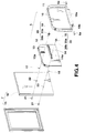
- the display case 7 is attached to the support unit 5, as shown in FIG. 4.
- the support unit 5 includes a substantially semicircular support plate 10 and an attaching plate 12 attached to a recess 11 in a face of the support plate 10 by screws.
- a first guide groove 13 is formed in the attaching plate 12 at an upper and right hand position thereof, extending in the vertical direction perpendicular to a shaft of hinges 6.
- a second guide groove 14 is also formed in the attaching plate 12 at a right hand position and under the first guide groove 13 thereof, extending in the horizontal direction parallel to the shaft of hinges 6.
- These first and second guide grooves 13 and 14 have collars 13a and 14a each being formed along that rim portion of the groove which is on the side of the display case 7.
- the display case 7 comprises a front case 15 in which the display section 8 is arranged, and a rear case 16 attached to the front case 15 by screws.
- First and second connecting members 17 and 18 are arranged in the rear case 16 at those positions thereof which correspond to the first and second guide grooves 13 and 14.
- the first connecting member (or rotation shaft) 17 includes a slide rotor 20 having a screw hole 19 along its center line, and an attaching screw 21 screwed into the screw hole 19 of the slide rotor 20.
- the attaching screw 21 is screwed into the screw hole 19 of the slide rotor 20, passing through a hole 22 in the rear case 16, in such a way that a larger-diameter portion 20a of the slide rotor 20 is freely movably arranged in the first guide groove 13, that a smaller-diameter portion 20b thereof is projected toward the rear case 16 through the collar 13a, and that a stepped portion of the slide rotor 20 between the larger 20a and the smaller-diameter portion 20b thereof is contacted with the collar 13a.
- the first connecting member 17 is in the rear case 16 below the center and at right hand position thereof, as shown in FIG. 4.
- the second connecting (or guide) member 18 includes a slide rotor 20 and an attaching screw 21, similarly to the case of the first connecting member 17.
- the attaching screw 21 is screwed into a screw hole 19 in the slide rotor 20, passing through a hole 23 in the rear case 16, in such a way that a larger-diameter portion 20a of the slide rotor 20 is freely movably arranged in the second guide groove 14, that a smaller-diameter portion 20b thereof is projected toward the rear case 16 through the collar 14a, and that a stepped portion of the slide rotor 20 between the larger 20a and the smaller-diameter portion 20b thereof is contacted with the collar 14a.
- the second connecting member 18 is substantially in the center on a line extending from the hole 22 in the rear case 16 to a lower left corner 16a of the case 16.
- the attaching plate 10 of the support unit 5 and the rear case 16 of the display case 7 are attached to each other by first and second connecting members 17 and 18 in such a way that the rear case 16 can be swung relative to the attaching plate 10 by 90°.
- the first and second guide grooves 13 and 14 are related to the first and second connecting members 17 and 18, as shown in FIGS. 5 and 6, to swing the display case 7 relative to the support unit 5 by 90°.
- FIGS. 5 and 6 are views gained when seeing the support unit 5 from the side of the rear case 16, and they are reverse to that shown in FIG. 4.
- the second connecting member 18 is located at the left side end of the second guide groove 14.
- the second connecting member 18 is positioned at the right side end of the second guide groove 14.
- the second guide groove 14 has such a linear length that allows the second connecting member 18 to be positioned at these points.
- the first guide groove 13 is formed to have such a linear length that the first connecting member 17 can be located to the lowest position in the groove 13 when the rear case 16 is set with its longer sides parallel to the horizontal direction and also parallel to the vertical direction, as shown by solid and broken lines in FIG. 5, and that it can be located to the top of the groove 13 when the case 16 is on the way of its being swung, as shown by a two-dot and dash line in FIG. 5.
- the lower left corner 16a of the rear case 16 draws a moving track shown in FIG. 6.
- the support unit 5 can be swingably attached to the body case 1 by hinges 6 as follows: A protrusion 10a projected from the lower end of the support plate 10 is arranged in the recess 4 of the body case 1 and shaft pins 6a attached to both end faces of the recess 4 are fitted into shaft holes 10b in both end faces of the protrusion 10a.
- Electric connection between the body case 1 and the display case 7 can be attained in such a way that a signal line, for example, is guided from the body case 1 into the support unit 5 through the hinge 6 and that it is then guided into the display case 7, passing through that portion of the support unit 5 which adjacent to the first connecting member 17 and which is by far less swung.
- switches are arranged at both ends of the second guide groove 14 and when they are switched on and off by the second connecting member 18, the display section 8 is changed over from horizontal display mode to vertical one and vice versa.
- the support unit 5 is swung round the hinges 6 to open and erect the display case 7, which has closed the key input section 2 of the body case 1, relative to the body case 1 by a certain angle (about 100 - 120° in this case).
- the display case 7 is thus erected with its longer sides parallel to the horizontal direction, as shown in FIG. 1.
- the display section 8 is therefore set with its longer sides parallel to the horizontal direction.
- the key input section 2 in the top of the body case 1 is thus exposed to thereby enable data to be inputted through the key input section 2.
- the display section 8 is set with its longer sides parallel to the horizontal direction. It is therefore quite suitable for displaying figures, tables and others.
- the display case 7 When the display section 8 is to be changed from horizontal state to vertical state, the display case 7 is swung relative to the support unit 5 in a certain direction (or counterclockwise in FIG. 1).
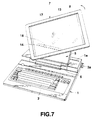
- the second connecting member 18 thus moves from the left side end to right along the second guide groove 14 while the first connecting member 17 from the lowest position to upward along the first guide groove 14, as shown in FIG. 7.
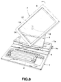
- the first connecting member 17 When the second connecting member 18 moves to the center of the second guide groove 14, as shown in FIG. 8, the first connecting member 17 is positioned at the top of the first guide groove 13 because the second connecting member 18 comes nearest to the first guide groove 13. This enables the lower corner of the display case 7 to be projected downward to an as smaller extent as possible.
- the first connecting member 17 is moved from the top to downward along the first guide groove 13.
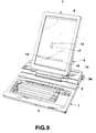
- the display case 7 is swung relative to the support unit 5 by 90° and it is thus changed over from the horizontal state to the vertical state, as shown in FIG. 9.
- the display section 8 is set to be under vertical state in this case. Therefore, characters in a line becomes fewer but lines of characters in the display section 8 becomes more. This makes the display section 8 more suitable for inputting documents and displaying them.
- the second connecting member 18 is positioned at the right side end of the second guide groove 14 under this state. Therefore, the switch arranged at the right side end of the second guide groove 14 is switched on by the second connecting member 18 to thereby select the display section 8 to be under the vertical display mode.
- the display case 7 When this information unit is to be carried by hand, the display case 7 is swung in a reverse direction (or clockwise) and it is changed over from the vertical state to the horizontal state. The support unit 5 is then swung relative to the body case 1 to thereby place the display case 7 upon the body case 1, as shown in FIG. 3.
- the information device can be made more compact to be carried by hand, like the wrap-top and note type ones.
- the first and second connecting members 17 and 18 move along the first and second guide grooves 13 and 14 and the second connecting member 18 comes to the center of the second guide groove 14 in this information unit, it comes nearest to the first guide groove 13.
- the first connecting member 17 is thus positioned at the top of the first guide groove 13. Therefore, the extent to which the lower corner of the display case 7 is projected downward can be made smaller. This makes it easier to change the display case 7 from the horizontal state to the vertical state and vice versa.
- the second connecting member 18 positions at either of both side ends of the second guide groove 14 while the first connecting member 17 at the lowest of the first guide groove.
- the first and second connecting members 17 and 18 are not allowed, therefore, to freely move along the first and second guide grooves 13 and 14. This makes the display case 7 more stable.
- the second connecting member 18 has been positioned between the first connecting member 17 and the lower left corner of the rear case 16 and the second guide groove 14 has been formed, parallel to the hinge shaft, in the attaching plate 12 of the support unit 5 in the above-described first embodiment, they may be arranged as shown in FIGS. 10 and 11.
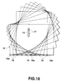
- the second connecting member 18 is positioned at the lower left corner 16a of the rear case 16 when the rear case 16 is under the horizontal state.
- the lower left corner 16a of the rear case 16 moves like a straight line, as shown in FIG. 10, not to project downward.
- a second guide groove 25 formed in the attaching plate 12 of the support unit 5 is shaped like a curve, enabling the second connecting member 18 to come nearer to the first guide groove 13 as it moves from either of both side ends of the groove 25 to the center thereof.
- first and second guide grooves 13 and 14 have been formed in the attaching plate 12 of the support unit 5 while the first and second connecting members 17 and 18 in the rear case 16 of the display case 7 in the above-described embodiments, it may be arranged that the first and second guide grooves 13 and 14 are formed in the rear case 16 of the display case 7 and that the holes 22 and 23 through which the first and second connecting members 17 and 18 are passed are formed in the attaching plate 12 of the support unit 5. Same effect can be attained in this case.
Landscapes
- Engineering & Computer Science (AREA)
- General Engineering & Computer Science (AREA)
- Theoretical Computer Science (AREA)
- Physics & Mathematics (AREA)
- Computer Hardware Design (AREA)
- Human Computer Interaction (AREA)
- General Physics & Mathematics (AREA)
- Mathematical Physics (AREA)
- Mechanical Engineering (AREA)
- Devices For Indicating Variable Information By Combining Individual Elements (AREA)
- Casings For Electric Apparatus (AREA)
- Document Processing Apparatus (AREA)
Description
- The invention relates to a mechanism for swinging a panel unit according to the first portion of
claim 1. - Information units such as personal computers have been made smaller and smaller and those of lap-top and note types having superior portability have been developed.
- In the case of the information units of these types, a key input section is arranged in the top of a unit case, a display case is swingably attached to the unit case to freely close the key input section, and a display section is arranged in that face of the display case which is opposed to the key input section.
- In these information units, the key input section is made longer in the horizontal direction, considering the arrangement of keys at the key input section. Therefore, the display case which covers the key input section is also made longer in the horizontal direction and the display section is thus made longer in the same direction. When the display case is swung and erected relative to the unit case, therefore, the display section is always kept longer in the horizontal direction. This display section which is kept in this manner makes it suitable for drawing something like figures in it. In a case where documents are created, however, characters in a line that can be inputted in it become more but lines of characters become fewer. This makes each user feel it difficult to use the information units as he expected. This was an undesirable drawback that the conventional information units had.
- In order to solve this drawback, therefore, information units capable of changing their display section to horizontal and vertical states have been discussed and proposed. A small-sized data process unit which has been disclosed as an example of these information units in JP-U-458725 includes a support attached to a unit body, which serves as a body case, by hinges and a cover, which serves as the display case, freely swingably attached to the support through a cylindrical swing shaft. More specifically, the swing shaft is erected from the rear face of the cover at an upper left position, nearer to the center, thereof, its front portion is inserted into a slot formed, parallel to a shaft of hinges, in the support at an upper left position thereof, and a flange at its front portion is contacted with a part of the rim of the slot, so that the cover can be freely swingably connected to the support. Further, the swing shaft includes a swing regulating projection arranged at a part of it and detachably engageable with engaging recesses at both ends of the slot. The case which is under horizontal state and also under vertical state can be thus regulated in position by the projection of the swing shaft not to freely move in the slot.
- In this small-sized data process unit, however, the slot in the support is formed substantially parallel to the shaft of hinges and one swing shaft is swingably and movably fitted into the slot. When the cover or display case is swung from horizontal to vertical state, therefore, a lower corner of the cover is projected to a great extent toward the device body or body case. In order to prevent the lower corner of the cover from being struck against the top of the device body in this case, the angle by which the cover is swung relative to the device body must be made larger than about 150°, for example. This made each user feel it troublesome to use the information device. Further, the cover is swung round one swing shaft in the information device. When the cover is to be swung to horizontal or vertical state, therefore, its swing must be regulated by a swing regulating means. In order to provide this swing regulating means, a swing regulating projection must be arranged on the swing shaft and engaging recesses must be formed in the slot. This made the swing shaft and the slot complicated in structure and their making became troublesome.
- EP-A1-0 055,662 describes to provide a display with cylinders on both sides of the display. These cylinders pass through grooves formed in a base portion to support the display by the base portion at both sides of the display. In this way it may be arranged in a horizontal position or an inclined position.
- The object of the present invention is therefore to provide a panel unit swing mechanism capable of more easily swing a panel unit from horizontal to vertical state and vice versa.
- This object is achieved by the technical teaching of
claim 1. - According to the present invention, therefore, the panel unit can be swung to either of horizontal and vertical states, and when it is swung, its lower corner cannot be projected downward to a great extent. In addition, it can be swung more stably and smoothly with a smaller force.
- This invention can be more fully understood from the following detailed description when taken in conjunction with the accompanying drawings, in which:
FIGS. 1 through 11 show some embodiments of the present invention, in which - FIG. 1 is a perspective view showing the panel unit swing mechanism according to a first embodiment of the present invention by which longer sides of a display case are set parallel to the horizontal direction;
- FIG. 2 is a sectional view taken along a line II - II in FIG. 1;
- FIG. 3 is a perspective view showing the display case closed onto a body case;
- FIG. 4 is a perspective view showing a support unit and the display case dismantled;
- FIG. 5 shows how first and second guide grooves and first and second connecting members are related to the body case when the display case is swung;
- FIG. 6 shows a moving track that a rear case draws when the display case is swung in FIG. 5;
- FIG. 7 is a perspective view showing the display case being about to be swung counterclockwise from the state shown in FIG. 1 under which its longer sides are kept parallel to the horizontal direction;
- FIG. 8 is a perspective view showing the display case being on the way of setting its longer sides parallel to the vertical direction from its state shown in FIG. 1;
- FIG. 9 is a perspective view showing the display case kept with its longer sides parallel to the vertical direction;
- FIG. 10 shows a mount position of a second connecting member according to a second embodiment of the present invention and a moving track that the display case draws in this case;
- FIG. 11 shows a shape of a second guide groove according to a third embodiment of the present invention and a moving track that the display case draws in this case.
-
- Referring to FIGS. 1 through 9, the panel unit swing mechanism according to a first embodiment of the present invention will be described.
- In FIGS. 1 through 3,
reference numeral 1 denotes a body case. It is shaped like a box, having a lower front portion and a higher rear portion. It has akey input section 2, which comprises various keys, at its lower front portion while it houses aprinter 3 in its higher rear portion, as shown in FIG. 3. It also has aslit 1a, through which sheets of recording paper are discharged, in the top of its higher rear portion and a recordingpaper feeding knob 3a on a side thereof, as shown in FIG. 3. It also has anarc recess 4 formed on a portion which rises from the rear end of its lower front portion, and asupport unit 5 is freely swingably attached to therecess 4 byhinges 6, as shown in FIG. 2. Adisplay case 7 which closes thekey input section 2 of thebody case 1 is attached, as will be described later, to thesupport unit 5. A panel-like display section 8 such as the liquid crystal display is arranged in thedisplay case 7, facing the top of thebody case 1. In the case of this information device, therefore, desired data can be inputted through thekey input section 2 and the data thus inputted can be displayed on thedisplay section 8 and printed on the recording paper by theprinter 3. - The
display case 7 is attached to thesupport unit 5, as shown in FIG. 4. Thesupport unit 5 includes a substantiallysemicircular support plate 10 and an attachingplate 12 attached to arecess 11 in a face of thesupport plate 10 by screws. Afirst guide groove 13 is formed in the attachingplate 12 at an upper and right hand position thereof, extending in the vertical direction perpendicular to a shaft ofhinges 6. Asecond guide groove 14 is also formed in the attachingplate 12 at a right hand position and under thefirst guide groove 13 thereof, extending in the horizontal direction parallel to the shaft ofhinges 6. These first and second guide grooves 13 and 14 havecollars display case 7. Thedisplay case 7 comprises afront case 15 in which thedisplay section 8 is arranged, and arear case 16 attached to thefront case 15 by screws. First and second connectingmembers rear case 16 at those positions thereof which correspond to the first andsecond guide grooves - The first connecting member (or rotation shaft) 17 includes a
slide rotor 20 having ascrew hole 19 along its center line, and an attachingscrew 21 screwed into thescrew hole 19 of theslide rotor 20. The attachingscrew 21 is screwed into thescrew hole 19 of theslide rotor 20, passing through ahole 22 in therear case 16, in such a way that a larger-diameter portion 20a of theslide rotor 20 is freely movably arranged in thefirst guide groove 13, that a smaller-diameter portion 20b thereof is projected toward therear case 16 through thecollar 13a, and that a stepped portion of theslide rotor 20 between the larger 20a and the smaller-diameter portion 20b thereof is contacted with thecollar 13a. When thedisplay case 7 is set with its longer sides parallel to the vertical direction, the first connectingmember 17 is in therear case 16 below the center and at right hand position thereof, as shown in FIG. 4. - The second connecting (or guide)
member 18 includes aslide rotor 20 and an attachingscrew 21, similarly to the case of the first connectingmember 17. The attachingscrew 21 is screwed into ascrew hole 19 in theslide rotor 20, passing through ahole 23 in therear case 16, in such a way that a larger-diameter portion 20a of theslide rotor 20 is freely movably arranged in thesecond guide groove 14, that a smaller-diameter portion 20b thereof is projected toward therear case 16 through thecollar 14a, and that a stepped portion of theslide rotor 20 between the larger 20a and the smaller-diameter portion 20b thereof is contacted with thecollar 14a. When thedisplay case 7 is set with its longer sides parallel to the vertical direction, the second connectingmember 18 is substantially in the center on a line extending from thehole 22 in therear case 16 to a lowerleft corner 16a of thecase 16. - Therefore, the attaching
plate 10 of thesupport unit 5 and therear case 16 of thedisplay case 7 are attached to each other by first and second connectingmembers rear case 16 can be swung relative to the attachingplate 10 by 90°. - The first and
second guide grooves members display case 7 relative to thesupport unit 5 by 90°. FIGS. 5 and 6 are views gained when seeing thesupport unit 5 from the side of therear case 16, and they are reverse to that shown in FIG. 4. When therear case 16 is set with its longer sides parallel to the horizontal direction, as shown by a solid line in FIG. 5, the second connectingmember 18 is located at the left side end of thesecond guide groove 14. When it is set with its longer sides parallel to the vertical direction, as shown by a broken line in FIG. 5, the second connectingmember 18 is positioned at the right side end of thesecond guide groove 14. Thesecond guide groove 14 has such a linear length that allows the second connectingmember 18 to be positioned at these points. Further, thefirst guide groove 13 is formed to have such a linear length that the first connectingmember 17 can be located to the lowest position in thegroove 13 when therear case 16 is set with its longer sides parallel to the horizontal direction and also parallel to the vertical direction, as shown by solid and broken lines in FIG. 5, and that it can be located to the top of thegroove 13 when thecase 16 is on the way of its being swung, as shown by a two-dot and dash line in FIG. 5. When therear case 16 is swung relative to the attachingplate 10 of thesupport unit 5 by 90°, therefore, the lowerleft corner 16a of therear case 16 draws a moving track shown in FIG. 6. - The
support unit 5 can be swingably attached to thebody case 1 byhinges 6 as follows: Aprotrusion 10a projected from the lower end of thesupport plate 10 is arranged in therecess 4 of thebody case 1 andshaft pins 6a attached to both end faces of therecess 4 are fitted intoshaft holes 10b in both end faces of theprotrusion 10a. - Electric connection between the
body case 1 and thedisplay case 7 can be attained in such a way that a signal line, for example, is guided from thebody case 1 into thesupport unit 5 through thehinge 6 and that it is then guided into thedisplay case 7, passing through that portion of thesupport unit 5 which adjacent to the first connectingmember 17 and which is by far less swung. - In the case of this information device, switches (not shown) are arranged at both ends of the
second guide groove 14 and when they are switched on and off by the second connectingmember 18, thedisplay section 8 is changed over from horizontal display mode to vertical one and vice versa. - In the case of this information device, the
support unit 5 is swung round thehinges 6 to open and erect thedisplay case 7, which has closed thekey input section 2 of thebody case 1, relative to thebody case 1 by a certain angle (about 100 - 120° in this case). Thedisplay case 7 is thus erected with its longer sides parallel to the horizontal direction, as shown in FIG. 1. Thedisplay section 8 is therefore set with its longer sides parallel to the horizontal direction. Thekey input section 2 in the top of thebody case 1 is thus exposed to thereby enable data to be inputted through thekey input section 2. In addition, thedisplay section 8 is set with its longer sides parallel to the horizontal direction. It is therefore quite suitable for displaying figures, tables and others. When thedisplay case 7 is under this state, the second connectingmember 18 is positioned at the left side end of thesecond guide groove 14. The switch arranged there is thus turned on by the second connectingmember 18 to thereby select thedisplay section 8 to be under horizontal display mode. - When the
display section 8 is to be changed from horizontal state to vertical state, thedisplay case 7 is swung relative to thesupport unit 5 in a certain direction (or counterclockwise in FIG. 1). The second connectingmember 18 thus moves from the left side end to right along thesecond guide groove 14 while the first connectingmember 17 from the lowest position to upward along thefirst guide groove 14, as shown in FIG. 7. When the second connectingmember 18 moves to the center of thesecond guide groove 14, as shown in FIG. 8, the first connectingmember 17 is positioned at the top of thefirst guide groove 13 because the second connectingmember 18 comes nearest to thefirst guide groove 13. This enables the lower corner of thedisplay case 7 to be projected downward to an as smaller extent as possible. When the second connectingmember 18 then moves from the center to the right side end along thesecond guide groove 14, the first connectingmember 17 is moved from the top to downward along thefirst guide groove 13. When the second connectingmember 18 moves from the left side end to the right side end along thesecond guide groove 14 in this manner, thedisplay case 7 is swung relative to thesupport unit 5 by 90° and it is thus changed over from the horizontal state to the vertical state, as shown in FIG. 9. Thedisplay section 8 is set to be under vertical state in this case. Therefore, characters in a line becomes fewer but lines of characters in thedisplay section 8 becomes more. This makes thedisplay section 8 more suitable for inputting documents and displaying them. The second connectingmember 18 is positioned at the right side end of thesecond guide groove 14 under this state. Therefore, the switch arranged at the right side end of thesecond guide groove 14 is switched on by the second connectingmember 18 to thereby select thedisplay section 8 to be under the vertical display mode. - When this information unit is to be carried by hand, the
display case 7 is swung in a reverse direction (or clockwise) and it is changed over from the vertical state to the horizontal state. Thesupport unit 5 is then swung relative to thebody case 1 to thereby place thedisplay case 7 upon thebody case 1, as shown in FIG. 3. When arranged so, the information device can be made more compact to be carried by hand, like the wrap-top and note type ones. - When the first and second connecting
members second guide grooves member 18 comes to the center of thesecond guide groove 14 in this information unit, it comes nearest to thefirst guide groove 13. The first connectingmember 17 is thus positioned at the top of thefirst guide groove 13. Therefore, the extent to which the lower corner of thedisplay case 7 is projected downward can be made smaller. This makes it easier to change thedisplay case 7 from the horizontal state to the vertical state and vice versa. When thedisplay case 7 is under the horizontal and vertical states, the second connectingmember 18 positions at either of both side ends of thesecond guide groove 14 while the first connectingmember 17 at the lowest of the first guide groove. The first and second connectingmembers second guide grooves display case 7 more stable. - Although the second connecting
member 18 has been positioned between the first connectingmember 17 and the lower left corner of therear case 16 and thesecond guide groove 14 has been formed, parallel to the hinge shaft, in the attachingplate 12 of thesupport unit 5 in the above-described first embodiment, they may be arranged as shown in FIGS. 10 and 11. - In a second embodiment shown in FIG. 10, the second connecting
member 18 is positioned at the lowerleft corner 16a of therear case 16 when therear case 16 is under the horizontal state. When thedisplay case 7 is changed over from the horizontal state to the vertical state and vice versa, therefore, the lowerleft corner 16a of therear case 16 moves like a straight line, as shown in FIG. 10, not to project downward. - In a third embodiment shown in FIG. 11, a
second guide groove 25 formed in the attachingplate 12 of thesupport unit 5 is shaped like a curve, enabling the second connectingmember 18 to come nearer to thefirst guide groove 13 as it moves from either of both side ends of thegroove 25 to the center thereof. When thedisplay case 7 is changed over from the horizontal state to the vertical state and vice versa, therefore, the lowerleft corner 16a of therear case 16 moves like a straight line, as seen in the case of the second embodiment. This prevents thecorner 16a of therear case 16 from being projected downward. - Although the first and
second guide grooves plate 12 of thesupport unit 5 while the first and second connectingmembers rear case 16 of thedisplay case 7 in the above-described embodiments, it may be arranged that the first andsecond guide grooves rear case 16 of thedisplay case 7 and that theholes members plate 12 of thesupport unit 5. Same effect can be attained in this case.
Claims (8)
- A panel unit swing mechanism for swingably supporting a rectangular plate-like panel unit (7) with respect to a support unit (5), and swinging the panel unit to switch the arrangement of said panel unit (7) to a first state in which the panel unit (7) is set with its longer sides parallel to the horizontal direction or to a second state in which it is set with its shorter sides parallel to the horizontal direction,
characterized by:a first coupling means (17) comprising a swing shaft arranged at a certain position in said panel unit (7) which couples said panel unit (7) to said support unit (5) and allows swinging of said panel unit (7) with respect to said support unit (5);a second coupling means (18) arranged in said panel unit (7) between a lower corner of said panel unit (7) and a position where said first coupling means (17) is arranged, which couples said panel unit (7) to said support unit (5) and regulates swinging movement of said panel unit (7) when said panel unit (7) is swung around with respect to said support unit (5):a substantially vertical guide groove (13) arranged in a vertical direction along said support unit (5), which guides said first coupling means (17) in such a way that said first coupling means (17) provided in said panel unit (7) can move in a vertical direction when said panel unit (7) is swung around; anda substantially horizontal guide grove (14) extending in a horizontal direction along said support unit (5) at a position lower than a position where said substantially vertical guide groove (13) is arranged, which guides said second coupling means (18) in such a a way that said second coupling means (18) provided in said panel unit (7) can move in a horizontal direction when said panel unit (7) is swung around, the substantially vertical guide groove (13) and the substantially horizontal guide groove (14) being arranged in the plane of said support unit in a substantially perpendicular relation. - A panel unit swing mechanism according to claim 1, characterized by using said panel unit swing mechanism with a personal information device provided with a body (1) having a key input section (2) in the top thereof, a panel unit (7) formed in a rectangular plate-like shape and having a display section (8) in a portion facing the key input section (2) in the body (1).
- The panel unit swing mechanism according to claim 1 or 2, characterized in that said first coupling means (17) is arranged at a certain position in said panel unit (7) in such a way that a bottom side of said panel unit (7) which is under the first state and a bottom side of said panel unit (7) which is under the second state are at the same position.
- The panel unit swing mechanism according to any one of claims 1 to 3,
characterized in that said horizontal guide groove (14) is formed like a straight line parallel to the bottom side of said panel unit (7) which is under the first state and that of said panel unit (7) which is under the second state. - The panel unit swing mechanism according to any of claims 1 to 3, characterized in that said horizontal guide groove (25) is shaped like a curve which comes nearer to the swing shaft (17) at its center.
- The panel unit swing mechanism according to any of claims 1 to 5, characterized in that said panel unit (7) includes a panel-like display (8).
- The panel unit swing mechanism according to any of claims 1 to 6, characterized in that said panel unit (7) swings in a range of 90° from the first state (FIG.1) to the second one (FIG.9) and vice versa.
- The panel unit swing mechanism according to any one of claims 1 to 7,
characterized in that said second coupling means is arranged at a lower corner of the panel unit.
Applications Claiming Priority (3)
| Application Number | Priority Date | Filing Date | Title |
|---|---|---|---|
| JP21831394A JP3322021B2 (en) | 1994-08-22 | 1994-08-22 | Information equipment |
| JP21831394 | 1994-08-22 | ||
| JP218313/94 | 1994-08-22 |
Publications (2)
| Publication Number | Publication Date |
|---|---|
| EP0703401A1 EP0703401A1 (en) | 1996-03-27 |
| EP0703401B1 true EP0703401B1 (en) | 1999-10-27 |
Family
ID=16717896
Family Applications (1)
| Application Number | Title | Priority Date | Filing Date |
|---|---|---|---|
| EP95112980A Expired - Lifetime EP0703401B1 (en) | 1994-08-22 | 1995-08-17 | Panel unit swing mechanism |
Country Status (6)
| Country | Link |
|---|---|
| US (1) | US5629833A (en) |
| EP (1) | EP0703401B1 (en) |
| JP (1) | JP3322021B2 (en) |
| KR (1) | KR100199777B1 (en) |
| CN (1) | CN1044042C (en) |
| DE (1) | DE69512987T2 (en) |
Cited By (1)
| Publication number | Priority date | Publication date | Assignee | Title |
|---|---|---|---|---|
| US7957778B2 (en) | 2006-07-27 | 2011-06-07 | Sharp Kabushiki Kaisha | Folding portable communications device |
Families Citing this family (60)
| Publication number | Priority date | Publication date | Assignee | Title |
|---|---|---|---|---|
| US5768163A (en) * | 1996-04-15 | 1998-06-16 | Hewlett-Packard | Versatile attachment of handheld devices to a host computing system |
| US5708561A (en) * | 1996-08-13 | 1998-01-13 | Vivek R. Huilgol | Portable computer having display slidably and rotatably mounted for movement between landscape and portrait orientation and to open and close speaker ports |
| US5730406A (en) * | 1996-09-17 | 1998-03-24 | Chen; Ping | Adjusting device for a display panel |
| US5768096A (en) * | 1996-10-30 | 1998-06-16 | Hewlett-Packard Company | Portable computer with movable display panels forming a concatenated display screen in response to opening the computer |
| JPH10319864A (en) * | 1997-05-09 | 1998-12-04 | Internatl Business Mach Corp <Ibm> | Mounting structure for display device and equipment provided with the same |
| US6859219B1 (en) | 1999-10-08 | 2005-02-22 | Gateway, Inc. | Method and apparatus having multiple display devices |
| US6522529B1 (en) | 2000-05-22 | 2003-02-18 | Vivek R. Huilgol | Rotatable computer display apparatus and method |
| JP2003084230A (en) * | 2001-09-07 | 2003-03-19 | Canon Inc | Display device |
| JP3595547B2 (en) * | 2002-08-22 | 2004-12-02 | シャープ株式会社 | Thin display device |
| US20050005932A1 (en) * | 2003-03-19 | 2005-01-13 | Berman Mitchell F. | Integrated anesthesia machine |
| JP4650997B2 (en) * | 2003-11-14 | 2011-03-16 | ユーエムイー・インシュアランス・インク | Multi-function mobile phone |
| US7092246B2 (en) * | 2003-11-18 | 2006-08-15 | Kabushiki Kaisha Toshiba | Apparatus for connecting a display to a body case of an electronic device |
| US20050146175A1 (en) * | 2004-01-02 | 2005-07-07 | Cottrell William D. | Vehicle mounted printer station |
| US7082028B2 (en) | 2004-07-08 | 2006-07-25 | Swivel It, Inc. | Rotatable computer display apparatus and method |
| US7708240B2 (en) * | 2004-07-29 | 2010-05-04 | Hewlett-Packard Development Company, L.P. | Computer docking system |
| JP2006072115A (en) * | 2004-09-03 | 2006-03-16 | Fuji Photo Film Co Ltd | Image display device |
| WO2006038554A1 (en) * | 2004-10-01 | 2006-04-13 | Sharp Kabushiki Kaisha | Mobile information terminal |
| JP4384059B2 (en) | 2005-01-31 | 2009-12-16 | シャープ株式会社 | Folding cell phone |
| JP4190509B2 (en) | 2005-03-02 | 2008-12-03 | シャープ株式会社 | Folding cell phone |
| KR101194606B1 (en) * | 2005-03-05 | 2012-10-25 | 엘지전자 주식회사 | Audio-visual system for vehicle |
| KR100709808B1 (en) * | 2005-03-31 | 2007-04-23 | 주식회사 팬택 | Rotating Slide Mobile Terminal |
| JP4588625B2 (en) * | 2005-12-22 | 2010-12-01 | パナソニック株式会社 | Mobile device |
| JP4227994B2 (en) | 2006-01-13 | 2009-02-18 | シャープ株式会社 | Foldable mobile device |
| JP4547354B2 (en) * | 2006-05-19 | 2010-09-22 | シャープ株式会社 | Foldable mobile communication device |
| JP2007312329A (en) * | 2006-05-22 | 2007-11-29 | Sharp Corp | Foldable mobile communication device |
| JP2007312330A (en) * | 2006-05-22 | 2007-11-29 | Sharp Corp | Foldable mobile communication device |
| JP2008028846A (en) * | 2006-07-24 | 2008-02-07 | Sharp Corp | Foldable mobile communication device |
| JP2008034946A (en) * | 2006-07-26 | 2008-02-14 | Sharp Corp | Folding cell phone |
| JP2008035024A (en) * | 2006-07-27 | 2008-02-14 | Sharp Corp | Foldable mobile device |
| JP4572183B2 (en) * | 2006-07-27 | 2010-10-27 | シャープ株式会社 | Foldable mobile device |
| CN101132676B (en) * | 2006-08-25 | 2010-09-01 | 宏达国际电子股份有限公司 | Hand-held electronic device with multiple operation modes |
| DE102006042077B4 (en) * | 2006-09-05 | 2008-06-12 | Lumberg Connect Gmbh | Mechanism for opening or closing a device |
| JP4638403B2 (en) | 2006-11-09 | 2011-02-23 | 株式会社山本精密 | Slide / rotary mounting unit and electronic equipment |
| JP4288287B2 (en) * | 2007-03-22 | 2009-07-01 | シャープ株式会社 | Foldable mobile terminal |
| JP4416804B2 (en) | 2007-03-26 | 2010-02-17 | シャープ株式会社 | Mobile device |
| CN101674952A (en) * | 2007-05-18 | 2010-03-17 | 麦格纳座椅公司 | Deployable center armrest |
| JP4888289B2 (en) | 2007-09-06 | 2012-02-29 | 富士通株式会社 | Connecting device and electronic device |
| JP5061366B2 (en) * | 2008-01-04 | 2012-10-31 | Necカシオモバイルコミュニケーションズ株式会社 | Hinge structure and folding electronic device |
| JP4764448B2 (en) * | 2008-03-21 | 2011-09-07 | レノボ・シンガポール・プライベート・リミテッド | Electronics |
| CN101551053B (en) * | 2008-04-02 | 2010-08-11 | 兆利科技工业股份有限公司 | Plane rotation mechanism of support device |
| US20090275366A1 (en) * | 2008-05-05 | 2009-11-05 | Schilling Donald L | Personal portable communication devices with deployable display systems for three dimensional visual representations and/or privacy and methods of use |
| KR101506035B1 (en) * | 2008-10-07 | 2015-03-25 | 엘지전자 주식회사 | Display device |
| JP5244138B2 (en) * | 2010-01-28 | 2013-07-24 | レノボ・シンガポール・プライベート・リミテッド | Electronics |
| US8230992B2 (en) * | 2010-03-15 | 2012-07-31 | Speculative Product Design, Llc | Tablet computer case for multiple viewing orientations |
| BR112012028204A2 (en) | 2010-06-07 | 2016-12-06 | Targus Group Internat Inc | portable electronic device wrap accessories and related systems and methods |
| US8315047B2 (en) * | 2010-07-08 | 2012-11-20 | Lenovo (Singapore) Pte. Ltd. | Rotatable display apparatus |
| US9080716B2 (en) * | 2012-04-16 | 2015-07-14 | World Richman Mfg. Corp. | Cradle apparatus and method for rotating and linearly displacing an electronic device |
| CN102767678A (en) * | 2012-05-26 | 2012-11-07 | 崔学晨 | Automatic rotating device for display screens of desktop computers |
| CN102767679A (en) * | 2012-05-26 | 2012-11-07 | 崔学晨 | Automatic rotating device for display screens of desktop computers |
| CN103195775A (en) * | 2013-04-15 | 2013-07-10 | 太仓博特精工机械设备有限公司 | Herringbone timbering |
| CN104750170A (en) * | 2013-12-25 | 2015-07-01 | 冠捷投资有限公司 | steerable support |
| US9750321B2 (en) | 2014-06-13 | 2017-09-05 | Targus Group International, Inc. | Case for portable electronic devices with internal support |
| AU2016201721B2 (en) | 2015-03-18 | 2017-05-18 | Targus International Llc | Extendable, universal case for portable electronic devices |
| JP6498138B2 (en) * | 2016-03-09 | 2019-04-10 | 三菱電機株式会社 | Monitor rotation mechanism and monitor equipped with the monitor rotation mechanism |
| CN109917855A (en) * | 2019-03-04 | 2019-06-21 | 联想(北京)有限公司 | A kind of electronic equipment |
| KR102446903B1 (en) * | 2020-06-08 | 2022-09-23 | 엘지전자 주식회사 | display device |
| TWI767533B (en) * | 2020-07-08 | 2022-06-11 | 仁寶電腦工業股份有限公司 | Display rotation mechanism and electronic device with rotatable display |
| CN112198928B (en) * | 2020-09-30 | 2023-05-02 | 联想(北京)有限公司 | Electronic equipment |
| US12474733B2 (en) * | 2023-01-31 | 2025-11-18 | Ncr Atleos Corporation | Configurable display holding apparatus and system |
| US20250328164A1 (en) * | 2024-04-17 | 2025-10-23 | National Products, Inc. | Dock with a rotatable mount for mobile devices and methods of making and using |
Family Cites Families (6)
| Publication number | Priority date | Publication date | Assignee | Title |
|---|---|---|---|---|
| FR2497371A1 (en) * | 1980-12-30 | 1982-07-02 | Cii Honeywell Bull | ERGONOMIC VISUALIZATION SYSTEM WITH AUTOMATIC CORRECTION OF THE READING DISTANCE ACCORDING TO THE TILT OF THE VISUAL |
| JP2612044B2 (en) * | 1988-07-21 | 1997-05-21 | 株式会社日立製作所 | Electronic file device |
| US4901973A (en) * | 1989-05-31 | 1990-02-20 | Ferrara Jr Daniel A | Support base for an air traffic controller's console or the like |
| JP2774672B2 (en) * | 1990-06-28 | 1998-07-09 | 東京電力株式会社 | Superconducting current limiter |
| JPH0458725U (en) | 1990-09-28 | 1992-05-20 | ||
| US5329289A (en) * | 1991-04-26 | 1994-07-12 | Sharp Kabushiki Kaisha | Data processor with rotatable display |
-
1994
- 1994-08-22 JP JP21831394A patent/JP3322021B2/en not_active Expired - Fee Related
-
1995
- 1995-08-07 US US08/511,886 patent/US5629833A/en not_active Expired - Lifetime
- 1995-08-17 EP EP95112980A patent/EP0703401B1/en not_active Expired - Lifetime
- 1995-08-17 DE DE69512987T patent/DE69512987T2/en not_active Expired - Lifetime
- 1995-08-22 CN CN95108650A patent/CN1044042C/en not_active Expired - Lifetime
- 1995-08-22 KR KR1019950025975A patent/KR100199777B1/en not_active Expired - Fee Related
Cited By (1)
| Publication number | Priority date | Publication date | Assignee | Title |
|---|---|---|---|---|
| US7957778B2 (en) | 2006-07-27 | 2011-06-07 | Sharp Kabushiki Kaisha | Folding portable communications device |
Also Published As
| Publication number | Publication date |
|---|---|
| KR100199777B1 (en) | 1999-06-15 |
| JP3322021B2 (en) | 2002-09-09 |
| KR960008475A (en) | 1996-03-22 |
| US5629833A (en) | 1997-05-13 |
| CN1118130A (en) | 1996-03-06 |
| HK1013434A1 (en) | 1999-08-27 |
| CN1044042C (en) | 1999-07-07 |
| DE69512987T2 (en) | 2000-03-30 |
| EP0703401A1 (en) | 1996-03-27 |
| JPH0863259A (en) | 1996-03-08 |
| DE69512987D1 (en) | 1999-12-02 |
Similar Documents
| Publication | Publication Date | Title |
|---|---|---|
| EP0703401A1 (en) | Panel unit swing mechanism | |
| US5081742A (en) | Hinge device having mechanism for stopping movable member at open position | |
| EP0404165B1 (en) | A portable apparatus having a divided portion for suitably guiding a cable electrically connecting a base unit and a display unit pivotably coupled to the base unit | |
| US20050105258A1 (en) | Apparatus for connecting a display to a body case of an electronic device | |
| EP0178800A2 (en) | Portable computer | |
| US7054145B2 (en) | Mechanism for adjusting a display | |
| KR20010070272A (en) | Electronic equipment and transmission device of button device used therein | |
| KR19980034363A (en) | Liquid crystal display device that can adjust the liquid crystal flat panel display left and right and up and down | |
| KR900006062B1 (en) | Housing structure of keyboard musical instrument | |
| US6262824B1 (en) | Information apparatus having infrared communication device for transmitting/receiving data | |
| KR920001306A (en) | Latch mechanism for holding the movable member in the closed position | |
| EP0793163A2 (en) | Portable computer | |
| JPH08185242A (en) | Information processing equipment | |
| JPH10331838A (en) | Hinge structure of electronic apparatus | |
| KR930005834B1 (en) | Portable pc | |
| US20070165386A1 (en) | Electronic apparatus | |
| HK1013434B (en) | Panel unit swing mechanism | |
| US7110249B2 (en) | Electronic apparatus | |
| JPH11161367A (en) | Portable information processing device | |
| JPH04281509A (en) | Structure for portable personal computer | |
| US5240427A (en) | Portable apparatus having cable electrically connecting display unit and base unit | |
| JP3110877B2 (en) | Tilt foot mechanism | |
| KR200260840Y1 (en) | Double hinge door instrument and electronic apparatus using the same | |
| US20050105952A1 (en) | Foldable keyboard | |
| JP2019123244A (en) | Image formation device |
Legal Events
| Date | Code | Title | Description |
|---|---|---|---|
| PUAI | Public reference made under article 153(3) epc to a published international application that has entered the european phase |
Free format text: ORIGINAL CODE: 0009012 |
|
| 17P | Request for examination filed |
Effective date: 19950817 |
|
| AK | Designated contracting states |
Kind code of ref document: A1 Designated state(s): DE FR GB |
|
| 17Q | First examination report despatched |
Effective date: 19970715 |
|
| RAP1 | Party data changed (applicant data changed or rights of an application transferred) |
Owner name: CASIO COMPUTER CO., LTD. |
|
| GRAG | Despatch of communication of intention to grant |
Free format text: ORIGINAL CODE: EPIDOS AGRA |
|
| GRAG | Despatch of communication of intention to grant |
Free format text: ORIGINAL CODE: EPIDOS AGRA |
|
| GRAH | Despatch of communication of intention to grant a patent |
Free format text: ORIGINAL CODE: EPIDOS IGRA |
|
| GRAH | Despatch of communication of intention to grant a patent |
Free format text: ORIGINAL CODE: EPIDOS IGRA |
|
| GRAA | (expected) grant |
Free format text: ORIGINAL CODE: 0009210 |
|
| AK | Designated contracting states |
Kind code of ref document: B1 Designated state(s): DE FR GB |
|
| REF | Corresponds to: |
Ref document number: 69512987 Country of ref document: DE Date of ref document: 19991202 |
|
| ET | Fr: translation filed | ||
| PLBE | No opposition filed within time limit |
Free format text: ORIGINAL CODE: 0009261 |
|
| STAA | Information on the status of an ep patent application or granted ep patent |
Free format text: STATUS: NO OPPOSITION FILED WITHIN TIME LIMIT |
|
| 26N | No opposition filed | ||
| REG | Reference to a national code |
Ref country code: GB Ref legal event code: IF02 |
|
| PGFP | Annual fee paid to national office [announced via postgrant information from national office to epo] |
Ref country code: GB Payment date: 20120815 Year of fee payment: 18 |
|
| PGFP | Annual fee paid to national office [announced via postgrant information from national office to epo] |
Ref country code: DE Payment date: 20120816 Year of fee payment: 18 Ref country code: FR Payment date: 20120823 Year of fee payment: 18 |
|
| GBPC | Gb: european patent ceased through non-payment of renewal fee |
Effective date: 20130817 |
|
| PG25 | Lapsed in a contracting state [announced via postgrant information from national office to epo] |
Ref country code: DE Free format text: LAPSE BECAUSE OF NON-PAYMENT OF DUE FEES Effective date: 20140301 |
|
| REG | Reference to a national code |
Ref country code: DE Ref legal event code: R119 Ref document number: 69512987 Country of ref document: DE Effective date: 20140301 |
|
| REG | Reference to a national code |
Ref country code: FR Ref legal event code: ST Effective date: 20140430 |
|
| PG25 | Lapsed in a contracting state [announced via postgrant information from national office to epo] |
Ref country code: GB Free format text: LAPSE BECAUSE OF NON-PAYMENT OF DUE FEES Effective date: 20130817 |
|
| PG25 | Lapsed in a contracting state [announced via postgrant information from national office to epo] |
Ref country code: FR Free format text: LAPSE BECAUSE OF NON-PAYMENT OF DUE FEES Effective date: 20130902 |