EP0703152A1 - One-piece plastic container for carbonated beverages - Google Patents
One-piece plastic container for carbonated beverages Download PDFInfo
- Publication number
- EP0703152A1 EP0703152A1 EP95109482A EP95109482A EP0703152A1 EP 0703152 A1 EP0703152 A1 EP 0703152A1 EP 95109482 A EP95109482 A EP 95109482A EP 95109482 A EP95109482 A EP 95109482A EP 0703152 A1 EP0703152 A1 EP 0703152A1
- Authority
- EP
- European Patent Office
- Prior art keywords
- container
- strap
- base structure
- formations
- longitudinal axis
- Prior art date
- Legal status (The legal status is an assumption and is not a legal conclusion. Google has not performed a legal analysis and makes no representation as to the accuracy of the status listed.)
- Granted
Links
Images


Classifications
-
- B—PERFORMING OPERATIONS; TRANSPORTING
- B65—CONVEYING; PACKING; STORING; HANDLING THIN OR FILAMENTARY MATERIAL
- B65D—CONTAINERS FOR STORAGE OR TRANSPORT OF ARTICLES OR MATERIALS, e.g. BAGS, BARRELS, BOTTLES, BOXES, CANS, CARTONS, CRATES, DRUMS, JARS, TANKS, HOPPERS, FORWARDING CONTAINERS; ACCESSORIES, CLOSURES, OR FITTINGS THEREFOR; PACKAGING ELEMENTS; PACKAGES
- B65D1/00—Containers having bodies formed in one piece, e.g. by casting metallic material, by moulding plastics, by blowing vitreous material, by throwing ceramic material, by moulding pulped fibrous material, by deep-drawing operations performed on sheet material
- B65D1/02—Bottles or similar containers with necks or like restricted apertures, designed for pouring contents
- B65D1/0223—Bottles or similar containers with necks or like restricted apertures, designed for pouring contents characterised by shape
- B65D1/0261—Bottom construction
- B65D1/0284—Bottom construction having a discontinuous contact surface, e.g. discrete feet
Definitions
- This invention relates generally to a one piece plastic carbonated beverage container with a footed base structure; and particularly, a container of this type molded with a reduced amount of plastic material.
- These containers are usually, although not exclusively, made from a polyethylene terephthalate (PET) polyester material using a blow molding process that biaxially orients and sets its molecular structure.
- PET polyethylene terephthalate
- a major difficulty in a filled and sealed carbonated container is controlling and minimizing the distortion of the footed base structure from the pressure created by the carbonated beverage. Under normal conditions, this pressure can exceed 75 PSI (5bar). Uncontrolled distortion can lead to a variety of problems.
- Container damage from buckling, creases, bumps and bulges in the feet and sidewall areas can lead to structural damage from concentrated stresses; in other cases this can lead to an aesthetically unpleasing shape.
- Containers with concentrated stresses may burst if subjected to impact.
- Another problem is an inconsistent fill level line position created by an inconsistent expansion of the container, most of which occurs in the base structure area. Fill line position consistency is important to consumers in that consumers often believe a fill level below standard signifies an underfed or unsealed container.
- an unfilled container must be able to stand upright in the filling machinery. Containers that fall over during conveying will adversely affect the cost and efficiency of filling operations. Stability is improved with a wide stance of the feet of the base structure. Another consideration is maximization of the area of each foot pad in contact with the conveyor or other supporting surface. Small foot pads tend to become caught and fall over in the machinery.
- This invention provides a plastic container for carbonated beverages which has a base structure extending downwardly from a generally tubular sidewall.
- the form of the base structure is developed from several shapes smoothly blended together. The shapes selected satisfy the need for stability when empty and when filled with a carbonated or other beverage and sealed. Pressure from the carbonation is expected to alter the container-as-molded-shape to a new and desirable container-as-filled-and-sealed-shape. In effect, the container-as-molded-shape influences or predetermines the form of the new container-as-filled-and-sealed-shape.
- achieving a desirable shape utilizes the natural tendency of the blow molding process to create a slightly thicker container wall section in areas of the container mold which are contacted first by the expanding parison as it inflates.
- the wall thickness of a central region of the base about a longitudinal axis, which blends to adjacent portions of a strap formation and which in turn extends substantially radially from the central region tend to be thicker than the wall thickness of the container sidewall and the foot pad of each downwardly hollow projection.
- the container shape upon pressurization, is predetermined to expand first in a region of the base structure adjacent to the merge point of the base to the sidewall.
- the strap formation which separates circumferentially adjacent pairs of support feet is itself partially separated by a downward extending wedge formation also partially positioned between the circumferentially adjacent pairs of feet. The forces acting on the strap are evenly distributed to the sidewall by this split and by adjacent areas.
- the preferred strap formation assumes a shape similar to a letter Y.
- the footed container of this invention is aesthetically pleasing, provides a stable wide stance support both before and after filling, meets other generally accepted industrial and consumer expectations, and is significantly lighter in weight than containers previously known.
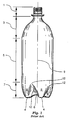
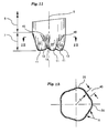
- Figure 1 illustrates a shape of a typical one piece footed carbonated beverage container.
- containers of this type have four broad regions, namely a neck finish (1), a shoulder portion (3), a sidewall portion (5), and a base structure (7).
- the base structure (7) comprises three, five, or six hollow foot projections (8) which extend downwardly in a arc from the sidewall (5) to provide the support for the container.
- a formation (10) which in the prior art is often referred to as a rib or a valley.
- This strap formation of the base structure extends radially outwardly and upwardly from a central region about a longitudinal axis (9) eventually blending with the sidewall (5) with a rounded point like shape (12).
- a nominal two liter container, for example, will often weight 55 grams or more.
- these containers are manufactured from a polyethylene terephthalate (PET) polyester plastic material using a blow molding process that biaxially orients and sets is molecular structure.
- PET polyethylene terephthalate
- Other materials such as polyethylene naphthalate (PEN) or some combination of terephthalate and naphthalate based materials can also be used. While these are the most likely choices, others may be considered as well.
- the plastic container of the invention has a base structure, when manufactured with a reduced amount of material, that allows controlled distortion to occur while alleviating the above mentioned problems.
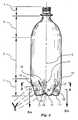
- This container as shown in Figure 2 includes a neck finish (1) merging with a shoulder portion (3) which in turn smoothly merges with a sidewall portion (5) which in turn smoothly merges with a closed base structure (7).
- the container provides stable support when empty and when filled with a carbonated beverage and sealed.
- the base structure (7) permits controlled expansion to primarily occur in an upper circumferential region near the lower end of the side wall portion (5).
- the base structure (7) is created by extending downwardly and smoothly inwardly from the sidewall (5) a minimum of three hollow projections or legs (35) disposed about the longitudinal axis (9) terminating in substantially planar foot pads (11) which in turn contact a support surface, not illustrated, thereby providing support for the one piece container.
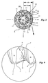
- Figure 3 is a bottom view of the base structure (7) of Figure 2. Separating each circumferentially adjacent pair of hollow projections (35) is a relatively stiff strap formation (13) which in turn divides to form separated strap formations (17). Together the strap formation (13) and the separated strap formations (17), when viewed longitudinally ( Figure 2), assume a shape similar to a letter Y. In Figure 3, the shape and features of a hollow projection (35), a foot pad (11), a strap formation (13), a pair of separated diverging strap formations (17), is repeated five times and evenly disposed about the center of the container. Five supporting feet is the preferred embodiment of the invention, but those skilled in the art will recognize the invention is not limited to five. Also shown is a central region (14) of base structure (7).
- each strap formation (13) starts at the central region (14), and extends between a pair of hollow feet (35) in a radially outward and upward direction from the axis (9).
- the strap formation (13) is then divided into diverging strap formations (17) which extend upwardly through the area of the base above the legs (35) to positions adjacent the lower end of the sidewall portion (5) of the container.
- the area of the base structure (7) located generally between the diverging strap formations, sometimes referred to as a wedge formation (15), is readily expanded as shown in broken lines in Fig. 5, when the container is filled with a carbonated beverage.
- the strap formations (17) are relatively stiff and thus act to confine the expansion in the area between the straps (17).
- the hollow feet (35) smoothly blend to the foot pads (11) with a substantially circular shaped boundary as shown in Figures 3 and 4.
- distance A ( Figure 3) is a distance from the center of the container to the sidewall (5).
- Distance B from the center of the container to the outer edge (21) of foot pad (11) is preferably 70 percent of distance A or greater. This positioning of the foot pads will provide the wide stance needed for improved stability.
- the substantially planar foot pad (11) shape (as shown in Figure 4) is the shape as manufactured. In combination with the wide stance, it contributes to the stability of the container in handling equipment before and during container filling. Once the container is filled with a carbonated beverage and sealed, the foot pad (11), in a controllable fashion, expands to assume a somewhat flat hemispheroidal shape (27) without creases or folds or other distortions which will detract from container stability. This is particularly true with the pad shape described above having a circular boundary.
- the wedge formation (15) merges from the sidewall portion (5) and is positioned circumferentially an equal distance from an adjacent pair of hollow projection (35).
- the strap formation (13) is separated by the wedge formation (15) to create separated strap formations (17) which in turn helps to distribute the forces of pressurization to the sidewall portion (5). Without this wedge formation (15) and separated strap formation (17), pressurization will concentrate forces in an area near the rounded point like shape (12) of prior art Figure 1.
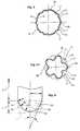
- the wedge formation (15) ( Figure 9) preferably has a shape with a rounded inverted triangular character (41), particularly when considering an imaginary line (39) created by the division of the base structure (7) merging from the sidewall portion (5).
- Figure 6 illustrates a bottom wall (29) of the base structure (7).
- the hollow projections (35) and wedge formations (15) are represented with phantom lines to better illustrate the shape of the bottom wall (29).
- Bottom wall (29) is a foundation shape from which the hollow projections (35) and wedge formations (15) extend. Once extended little of the bottom wall (29) configuration remains; nevertheless, the bottom wall (29) configuration is an important element of the base structure configuration after the container is filled with a carbonated beverage and sealed.
- the bottom wall (29) is shaped from an inverted truncated conical section (31) with a side angle ⁇ smoothly merging with a radius R1 from the sidewall portion (5).
- Smoothly merging downwardly with radius R2 from the conical section (31) is a spherical segment (33) with radius R3.
- Radius R3 can be either less than, equal to, or greater than dimension A.
- the surface of conical section (31) is not tangential to the surface of spherical segment (33).
- Figures 7 and 8 illustrate a view of the strap formation (13).
- Figure 7 is a bottom view of the base structure identical to Figure 3 except that most contour lines depicting shape have been eliminated to better show section 8-8 location.
- Figure 8 is an enlarged partial cross sectional view of the strap formation (13) and its relationship to the bottom wall (29).
- the strap formation (13) is actually a transition zone with a radius between adjacent pairs of hollow projections (35) and in close proximity to the bottom wall (29).
- Point 37 is the only remaining portion of the strap formation (13) in common with the bottom wall (29) when viewed in Figures 7 and 8.
- point (37) becomes a locus of points as the strap formation (13) extends from the central region (14) to the corresponding separated strap formations (17).
- the locus of points (37) continues in the separated strap formations (17) to merge with the sidewall (5).
- FIG. 5 there is shown a cross sectional view of base structure (7) along line 5-5 in Figure 2. Details lying beyond the cross section taken are omitted for clarity. Likewise, the repeating features of the hollow projections (35), separated strap formations (17), and wedge formations (15) are not all numbered. A grouping of one set of these features, including two separated strap formations (17), is repeated five times, and each group is circumferentially evenly spaced.
- the cross sectional view clearly illustrates an inside surface (16) and an outside surface (18).
- the hollow projections (35) appear to thrust slightly outward in a somewhat radial direction while the strap formations (13) appear to flatten slightly.
- the foot pads (11) assume a slightly somewhat hemispheriodal shape while the base structure (7) provides a stable container support.
- Figure 13 is a graphical representation, at various levels of pressure within the container, of the position of central region (6, 14) relative to the support foot pads (4,11).
- the position of central region (6) of a tested prior art container steadily decreases as pressure increases.
- the position of central region (14) of a tested container of this invention ( Figure 2) initially increased before decreasing as pressure increases.
- the central region (14, Figure 2) is at a position approximately equal to its position prior to filling.
- Figure 5a is a cross sectional view of base structure (7) along line 5a-5a in Figure 2 clearly illustrating strap formation (13) position relative to the hollow projections (35).
- Phantom line (20) represents the outer surface (18) of section 5-5 of Figure 5 and illustrates the separated strap formations (17) and wedge formation (15) in relationship to strap formation (13) and hollow projections (35).
- Figure 10 illustrates a modified form of the wedge formation (15) ( Figure 9) and the separated strap formations (17), wherein two or more smaller wedge formations (15b) separate strap formation (13) into three or more separated strap formations (17).
- Figures 11 and 12 illustrate an alternative configuration of the base structure (7), wherein the strap formation (13) extending substantially radially from the central region (14) merges with a fan shaped formation or area (45) forms a section in common with the bottom wall (29) ( Figure 6) resulting in a gentle radius as shown in Figure 12. Also shown are hollow projections (35) merging with a radius to the fan shaped strap formations (45).
- this invention provides a lightweight beverage container which can be made with a reduced amount of plastic.
- This objective is achieved by providing the container with circumferentially adjacent pairs of feet (35) which define, support, and are separated by, relatively stiff feet strap formations (13) each extending substantially radially from a central region (14) of the base structure, centered on the longitudinal axis (9), to a relatively deformable area (15) of the base structure located radially outwardly of the feet and adjacent to said the wall portion 5, each said strap formation (13) terminating at its radially outer end (26) in diverging strap formations (17) separated by a deformable area (15) which can expand outwardly between the diverging strap formations, said deformable area being located above said outer ends (13a) of said strap formations (13) and extending upwardly to a position adjacent the sidewall portion (5) of the container whereby initial internal pressurization of the container will expand the deformable area (15) radially outwardly away from the longitudinal axis, which in turn moves the
- the result is an improved container which is reliable in standing on a flat surface, is economical to manufacture, and which effectively accomodates expansion while resisting deformation when filled with a carbonated beverage.
Landscapes
- Engineering & Computer Science (AREA)
- Ceramic Engineering (AREA)
- Mechanical Engineering (AREA)
- Containers Having Bodies Formed In One Piece (AREA)
- Details Of Rigid Or Semi-Rigid Containers (AREA)
Abstract
Description
- This invention relates generally to a one piece plastic carbonated beverage container with a footed base structure; and particularly, a container of this type molded with a reduced amount of plastic material. These containers are usually, although not exclusively, made from a polyethylene terephthalate (PET) polyester material using a blow molding process that biaxially orients and sets its molecular structure.
- A major difficulty in a filled and sealed carbonated container is controlling and minimizing the distortion of the footed base structure from the pressure created by the carbonated beverage. Under normal conditions, this pressure can exceed 75 PSI (5bar). Uncontrolled distortion can lead to a variety of problems.
- One problem is poor container stability from a "rocker bottom" where the central region of the base bulges downwardly to a point where the supporting feet cannot simultaneously contact a supporting surface. In this case, the container is supported in a tilted somewhat unstable position by the central region and two of the feet.
- Another problem is container damage from buckling, creases, bumps and bulges in the feet and sidewall areas. In some cases, this can lead to structural damage from concentrated stresses; in other cases this can lead to an aesthetically unpleasing shape. Containers with concentrated stresses may burst if subjected to impact.
- Another problem is an inconsistent fill level line position created by an inconsistent expansion of the container, most of which occurs in the base structure area. Fill line position consistency is important to consumers in that consumers often believe a fill level below standard signifies an underfed or unsealed container.
- Also to be considered is that an unfilled container must be able to stand upright in the filling machinery. Containers that fall over during conveying will adversely affect the cost and efficiency of filling operations. Stability is improved with a wide stance of the feet of the base structure. Another consideration is maximization of the area of each foot pad in contact with the conveyor or other supporting surface. Small foot pads tend to become caught and fall over in the machinery.
- The prior art describes many examples of one piece plastic carbonated beverage containers with footed base structures. To achieve success, such containers depend on a relatively heavier container with substantial material thickness in the base structure area. The approach uses mass to resist distortion, but heavier containers tend to be costly to produce. When these containers are made with less material, many of the problems mentioned above occur. Those containers which tend to be lighter in weight tend to reduce the stance of the feet or reduce the area of each foot pad which often create stability problems before and after filling.
- It is, therefore, desirable to provide a footed carbonated beverage container of reduced material weight with a wide stance of the base structure feet and a large foot pad area while controlling and manipulating the expansion and distortion of the base from the beverage carbonation pressure so as not to adversely affect the consistency of fill line position, aesthetic appearance, stability, or to create excessive concentrated stresses.
- This invention provides a plastic container for carbonated beverages which has a base structure extending downwardly from a generally tubular sidewall. The form of the base structure is developed from several shapes smoothly blended together. The shapes selected satisfy the need for stability when empty and when filled with a carbonated or other beverage and sealed. Pressure from the carbonation is expected to alter the container-as-molded-shape to a new and desirable container-as-filled-and-sealed-shape. In effect, the container-as-molded-shape influences or predetermines the form of the new container-as-filled-and-sealed-shape.
- In accordance with this invention, achieving a desirable shape utilizes the natural tendency of the blow molding process to create a slightly thicker container wall section in areas of the container mold which are contacted first by the expanding parison as it inflates. In the case of the container of this invention, the wall thickness of a central region of the base about a longitudinal axis, which blends to adjacent portions of a strap formation and which in turn extends substantially radially from the central region, tend to be thicker than the wall thickness of the container sidewall and the foot pad of each downwardly hollow projection.
- The container shape, upon pressurization, is predetermined to expand first in a region of the base structure adjacent to the merge point of the base to the sidewall. The strap formation which separates circumferentially adjacent pairs of support feet is itself partially separated by a downward extending wedge formation also partially positioned between the circumferentially adjacent pairs of feet. The forces acting on the strap are evenly distributed to the sidewall by this split and by adjacent areas. When viewing the container longitudinally, the preferred strap formation assumes a shape similar to a letter Y.
- The footed container of this invention is aesthetically pleasing, provides a stable wide stance support both before and after filling, meets other generally accepted industrial and consumer expectations, and is significantly lighter in weight than containers previously known.
- Further advantages of the invention will become apparent to those skilled in the art from the following description, taken in connection with the accompanying drawings, in which:
- Figure 1 is a side elevational view of a prior art container;
- Figure 2 is a side elevational view of a container with a base structure of the present invention;
- Figure 3 is a bottom view of the container of Figure 2 illustrating five identical circumferentially spaced downwardly hollow foot projections of the base structure;
- Figure 4 is an enlarged elevational view of an area between a pair of downwardly hollow foot projections;
- Figure 5 is a sectional view as seen along line 5-5 of Figure 2;
- Figure 5a is a sectional view as seen along line 5-5 of Figure 2;
- Figure 6 is an elevational view of the base structure illustrated in phantom so as to better view a bottom wall from which the downwardly hollow foot projections project;
- Figure 7 is a bottom view similar to Figure 3 except that most shading detail is removed to better illustrate the position of section line 8-8;
- Figure 8 is an enlarged sectional view as seen along line 8-8 of Figure 7 illustrating a shape for the area between a pair of downwardly hollow foot projections;
- Figure 9 is an enlarged elevational view of a wedge formation between a pair of downwardly hollow foot projections essentially as seen in Figure 2, including an illustrated elemental shape as it generally appears to the eye;
- Figure 10 is an enlarged elevational view like Figure 9 of an alternative separated strap formation;
- Figure 11 is a partial side elevational view of an alternative configuration of the base of the present invention;
- Figure 12 is a sectional view as seen along line 12-12 of Figure 11; and
- Figure 13 is a graphical representation, at various levels of pressure within the container, of central region positions relative to the support foot pads.
- With reference to the drawings, Figure 1 illustrates a shape of a typical one piece footed carbonated beverage container. Generally containers of this type have four broad regions, namely a neck finish (1), a shoulder portion (3), a sidewall portion (5), and a base structure (7). Typically the base structure (7) comprises three, five, or six hollow foot projections (8) which extend downwardly in a arc from the sidewall (5) to provide the support for the container. Between any pair of these foot projections (8) is a formation (10) which in the prior art is often referred to as a rib or a valley. This strap formation of the base structure extends radially outwardly and upwardly from a central region about a longitudinal axis (9) eventually blending with the sidewall (5) with a rounded point like shape (12). A nominal two liter container, for example, will often weight 55 grams or more.
- These prior art containers generally work well, but in applications where the amount of material or weight of the container is reduced, to minimize manufacturing cost, (for example reductions to 50 grams or 48 grams or less in a two liter sized container) distortions can occur from the beverage carbonation pressure that will greatly influence container stability, performance, and aesthetic appeal. These distortions can create unwanted surface buckling, creases, and bulges in areas in the foot projections (8), the in-between formations (10), near the rounded point (12), and in the central base region about axis (9). These distortions often concentrate structural stresses in these areas which in turn can lead to a container breach if subjected to impact.
- Typically, these containers are manufactured from a polyethylene terephthalate (PET) polyester plastic material using a blow molding process that biaxially orients and sets is molecular structure. Other materials such as polyethylene naphthalate (PEN) or some combination of terephthalate and naphthalate based materials can also be used. While these are the most likely choices, others may be considered as well.
- The plastic container of the invention has a base structure, when manufactured with a reduced amount of material, that allows controlled distortion to occur while alleviating the above mentioned problems. This container as shown in Figure 2 includes a neck finish (1) merging with a shoulder portion (3) which in turn smoothly merges with a sidewall portion (5) which in turn smoothly merges with a closed base structure (7). The container provides stable support when empty and when filled with a carbonated beverage and sealed. The base structure (7) permits controlled expansion to primarily occur in an upper circumferential region near the lower end of the side wall portion (5).
- The base structure (7) is created by extending downwardly and smoothly inwardly from the sidewall (5) a minimum of three hollow projections or legs (35) disposed about the longitudinal axis (9) terminating in substantially planar foot pads (11) which in turn contact a support surface, not illustrated, thereby providing support for the one piece container.
- Figure 3 is a bottom view of the base structure (7) of Figure 2. Separating each circumferentially adjacent pair of hollow projections (35) is a relatively stiff strap formation (13) which in turn divides to form separated strap formations (17). Together the strap formation (13) and the separated strap formations (17), when viewed longitudinally (Figure 2), assume a shape similar to a letter Y. In Figure 3, the shape and features of a hollow projection (35), a foot pad (11), a strap formation (13), a pair of separated diverging strap formations (17), is repeated five times and evenly disposed about the center of the container. Five supporting feet is the preferred embodiment of the invention, but those skilled in the art will recognize the invention is not limited to five. Also shown is a central region (14) of base structure (7).
- It can thus be seen that each strap formation (13) starts at the central region (14), and extends between a pair of hollow feet (35) in a radially outward and upward direction from the axis (9). The strap formation (13) is then divided into diverging strap formations (17) which extend upwardly through the area of the base above the legs (35) to positions adjacent the lower end of the sidewall portion (5) of the container. The area of the base structure (7), located generally between the diverging strap formations, sometimes referred to as a wedge formation (15), is readily expanded as shown in broken lines in Fig. 5, when the container is filled with a carbonated beverage. The strap formations (17) are relatively stiff and thus act to confine the expansion in the area between the straps (17).
- Preferably, the hollow feet (35) smoothly blend to the foot pads (11) with a substantially circular shaped boundary as shown in Figures 3 and 4. distance A (Figure 3) is a distance from the center of the container to the sidewall (5). Distance B from the center of the container to the outer edge (21) of foot pad (11) is preferably 70 percent of distance A or greater. This positioning of the foot pads will provide the wide stance needed for improved stability.
- The substantially planar foot pad (11) shape (as shown in Figure 4) is the shape as manufactured. In combination with the wide stance, it contributes to the stability of the container in handling equipment before and during container filling. Once the container is filled with a carbonated beverage and sealed, the foot pad (11), in a controllable fashion, expands to assume a somewhat flat hemispheroidal shape (27) without creases or folds or other distortions which will detract from container stability. This is particularly true with the pad shape described above having a circular boundary.
- Turning to Figure 9, an enlarged segment of the base formation of the invention is illustrated. The wedge formation (15) merges from the sidewall portion (5) and is positioned circumferentially an equal distance from an adjacent pair of hollow projection (35). The strap formation (13) is separated by the wedge formation (15) to create separated strap formations (17) which in turn helps to distribute the forces of pressurization to the sidewall portion (5). Without this wedge formation (15) and separated strap formation (17), pressurization will concentrate forces in an area near the rounded point like shape (12) of prior art Figure 1.
- To the eye, the wedge formation (15) (Figure 9) preferably has a shape with a rounded inverted triangular character (41), particularly when considering an imaginary line (39) created by the division of the base structure (7) merging from the sidewall portion (5).
- Figure 6 illustrates a bottom wall (29) of the base structure (7). The hollow projections (35) and wedge formations (15) are represented with phantom lines to better illustrate the shape of the bottom wall (29). Bottom wall (29) is a foundation shape from which the hollow projections (35) and wedge formations (15) extend. Once extended little of the bottom wall (29) configuration remains; nevertheless, the bottom wall (29) configuration is an important element of the base structure configuration after the container is filled with a carbonated beverage and sealed.
- The bottom wall (29) is shaped from an inverted truncated conical section (31) with a side angle α smoothly merging with a radius R1 from the sidewall portion (5). Smoothly merging downwardly with radius R2 from the conical section (31) is a spherical segment (33) with radius R3. Radius R3 can be either less than, equal to, or greater than dimension A. The surface of conical section (31) is not tangential to the surface of spherical segment (33).
- Figures 7 and 8 illustrate a view of the strap formation (13). Figure 7 is a bottom view of the base structure identical to Figure 3 except that most contour lines depicting shape have been eliminated to better show section 8-8 location. Figure 8 is an enlarged partial cross sectional view of the strap formation (13) and its relationship to the bottom wall (29). The strap formation (13) is actually a transition zone with a radius between adjacent pairs of hollow projections (35) and in close proximity to the bottom wall (29).
Point 37 is the only remaining portion of the strap formation (13) in common with the bottom wall (29) when viewed in Figures 7 and 8. - In the base structure (7), point (37) becomes a locus of points as the strap formation (13) extends from the central region (14) to the corresponding separated strap formations (17). The locus of points (37) continues in the separated strap formations (17) to merge with the sidewall (5).
- Turning now to Figure 5, there is shown a cross sectional view of base structure (7) along line 5-5 in Figure 2. Details lying beyond the cross section taken are omitted for clarity. Likewise, the repeating features of the hollow projections (35), separated strap formations (17), and wedge formations (15) are not all numbered. A grouping of one set of these features, including two separated strap formations (17), is repeated five times, and each group is circumferentially evenly spaced. The cross sectional view clearly illustrates an inside surface (16) and an outside surface (18).
- Upon pressurization with a carbonated beverage, the circumferential region of the base structure as shown in Figure 5 easily expands to assume a smoother more rounded shape as shown by phantom line (19) representing a new position for the outside surface (18). The degree of smoothing is dependent on the amount of pressure applied by the beverage. In an extreme situation, the separated strap formations (17) will become difficult to detect and the wedge formation (15) will become a rounded bulge. It appears that this expansion allows a pivotal force to be applied to the relatively rigid strap formations (13) allowing the central region (14) to initially move upwardly relative to the support foot pads (11). As pressure quickly continues to build inside the container, the shoulder portion (3) and sidewall portion (5) expand slightly radially outward. The central region (14) returns to approximately its original position. The hollow projections (35) appear to thrust slightly outward in a somewhat radial direction while the strap formations (13) appear to flatten slightly. The foot pads (11) assume a slightly somewhat hemispheriodal shape while the base structure (7) provides a stable container support.
- Figure 13 is a graphical representation, at various levels of pressure within the container, of the position of central region (6, 14) relative to the support foot pads (4,11). The position of central region (6) of a tested prior art container (Figure 1) steadily decreases as pressure increases. The position of central region (14) of a tested container of this invention (Figure 2) initially increased before decreasing as pressure increases. At 75 PSI, the pressure of a typical carbonated beverage container filled and sealed at room temperature, the central region (14, Figure 2) is at a position approximately equal to its position prior to filling.
- Figure 5a is a cross sectional view of base structure (7) along
line 5a-5a in Figure 2 clearly illustrating strap formation (13) position relative to the hollow projections (35). Phantom line (20) represents the outer surface (18) of section 5-5 of Figure 5 and illustrates the separated strap formations (17) and wedge formation (15) in relationship to strap formation (13) and hollow projections (35). - Figure 10 illustrates a modified form of the wedge formation (15) (Figure 9) and the separated strap formations (17), wherein two or more smaller wedge formations (15b) separate strap formation (13) into three or more separated strap formations (17).
- Figures 11 and 12 illustrate an alternative configuration of the base structure (7), wherein the strap formation (13) extending substantially radially from the central region (14) merges with a fan shaped formation or area (45) forms a section in common with the bottom wall (29) (Figure 6) resulting in a gentle radius as shown in Figure 12. Also shown are hollow projections (35) merging with a radius to the fan shaped strap formations (45).
- From the above description, it is seen that this invention provides a lightweight beverage container which can be made with a reduced amount of plastic. This objective is achieved by providing the container with circumferentially adjacent pairs of feet (35) which define, support, and are separated by, relatively stiff feet strap formations (13) each extending substantially radially from a central region (14) of the base structure, centered on the longitudinal axis (9), to a relatively deformable area (15) of the base structure located radially outwardly of the feet and adjacent to said the wall portion 5, each said strap formation (13) terminating at its radially outer end (26) in diverging strap formations (17) separated by a deformable area (15) which can expand outwardly between the diverging strap formations, said deformable area being located above said outer ends (13a) of said strap formations (13) and extending upwardly to a position adjacent the sidewall portion (5) of the container whereby initial internal pressurization of the container will expand the deformable area (15) radially outwardly away from the longitudinal axis, which in turn moves the radially outer ends of the relatively stiff strap formations (13) radially outwardly and upwardly away from the longitudinal axis, thereby pivoting the strap formations (13) about their support by the feet and moving the radially inner ends of the strap formations generally upwardly toward the neck finish (1), thereby moving the central region (14) of the base along the longitudinal axis 9 toward the neck finish.
- The result is an improved container which is reliable in standing on a flat surface, is economical to manufacture, and which effectively accomodates expansion while resisting deformation when filled with a carbonated beverage.
- While the above description discloses the preferred embodiment of the invention, it will become apparent to those skilled in the art that modifications, and alterations may be made without deviating from the invention's scope and spirit as defined in the following claims.
Claims (5)
- A self standing blow molded polyester container for carbonated beverages, said container having a longitudinal axis (9) and a neck finish (1) integral with and terminating in a shoulder portion (3) which is integral with and terminates in a side wall portion (5) which is integral with and terminates in a closed base structure (7); the shoulder portion, side wall portion and the base structure being biaxially oriented; and the base structure being of a form defining a plurality of equally spaced feet (35) disposed about the longitudinal axis whereby the container is self standing, characterized in that:
circumferentially adjacent pairs of the feet (35) define, support, and are separated by, relatively stiff strap formations (13) each extending substantially radially from a central region (14) of the base structure, centered on the longitudinal axis (9), to a relatively deformable area (15) of the base structure located radially outwardly of the feet and adjacent to said side wall portion, each said strap formation terminating at its radially outer end (26) in diverging strap formations (17) separated by a deformable area (15) which can expand outwardly between the diverging strap formations, said deformable area being located above said outer (13a) ends of said strap formations (13) and extending upwardly to a position adjacent the sidewall portion (5) of the container whereby initial internal pressurization of the container will expand the deformable (15) area radially outwardly away from the longitudinal axis, which in turn moves the radially outer ends of the relatively stiff strap formations (13) radially outwardly and upwardly away from the longitudinal axis, thereby pivoting the strap formations (13) about their support by the feet and moving the radially inner ends of the strap formations (13) generally upwardly toward the neck finish, thereby moving the central region (14) of the base along the longitudinal axis (9) toward the neck finish. - The container according to claim 1 wherein said deformable area is a wedge shape bubble which projects radially outwardly from said container a location between a circumferentially adjacent pair of said legs.
- The container according to claim 1 wherein said deformable area is of a fan shape.
- The container according to claim 2 wherein said wedge formation and the adjacent separated strap formations separated by said wedge formation smoothly deform such that said wedge formation becomes a rounded bulge.
- The container according to claim 1 wherein five similar feet are evenly circumferentially disposed about said longitudinal axis.
Applications Claiming Priority (2)
| Application Number | Priority Date | Filing Date | Title |
|---|---|---|---|
| US303855 | 1994-09-09 | ||
| US08/303,855 US5529196A (en) | 1994-09-09 | 1994-09-09 | Carbonated beverage container with footed base structure |
Publications (2)
| Publication Number | Publication Date |
|---|---|
| EP0703152A1 true EP0703152A1 (en) | 1996-03-27 |
| EP0703152B1 EP0703152B1 (en) | 1998-09-16 |
Family
ID=23174006
Family Applications (1)
| Application Number | Title | Priority Date | Filing Date |
|---|---|---|---|
| EP95109482A Expired - Lifetime EP0703152B1 (en) | 1994-09-09 | 1995-06-20 | One-piece plastic container for carbonated beverages |
Country Status (14)
| Country | Link |
|---|---|
| US (1) | US5529196A (en) |
| EP (1) | EP0703152B1 (en) |
| JP (1) | JPH0885531A (en) |
| CN (1) | CN1119616A (en) |
| AU (1) | AU684168B2 (en) |
| BG (1) | BG99761A (en) |
| BR (1) | BR9503952A (en) |
| CA (1) | CA2153368A1 (en) |
| CZ (1) | CZ229895A3 (en) |
| DE (1) | DE69504793T2 (en) |
| ES (1) | ES2123861T3 (en) |
| HU (1) | HUT72551A (en) |
| PL (1) | PL310297A1 (en) |
| TR (1) | TR199501103A2 (en) |
Cited By (6)
| Publication number | Priority date | Publication date | Assignee | Title |
|---|---|---|---|---|
| WO2000002783A1 (en) * | 1998-07-10 | 2000-01-20 | Crown Cork & Seal Technologies Corporation | Footed container and base therefor |
| US6062409A (en) * | 1997-12-05 | 2000-05-16 | Crown Cork & Seal Technologies Corporation | Hot fill plastic container having spaced apart arched ribs |
| AU729565B2 (en) * | 1997-10-22 | 2001-02-01 | VisyPET Pty Limited | Base for PET bottle with improved stability |
| FR2892048A1 (en) * | 2005-10-17 | 2007-04-20 | Sidel Sas | MOLD BOTTOM FOR MOLD FOR MANUFACTURING THERMOPLASTIC CONTAINERS, AND MOLDING DEVICE EQUIPPED WITH AT LEAST ONE MOLD EQUIPPED WITH SUCH A BOTTOM. |
| WO2012069759A1 (en) * | 2010-11-25 | 2012-05-31 | Sidel Participations | Combined petaloid base of a container |
| EP2697125B1 (en) * | 2011-04-12 | 2018-07-04 | Sidel Participations | Double-valley petaloid container bottom |
Families Citing this family (33)
| Publication number | Priority date | Publication date | Assignee | Title |
|---|---|---|---|---|
| JP3612775B2 (en) * | 1995-03-28 | 2005-01-19 | 東洋製罐株式会社 | Heat-resistant pressure-resistant self-supporting container and manufacturing method thereof |
| AU733235B2 (en) * | 1996-12-20 | 2001-05-10 | Ball Corporation | Plastic container for carbonated beverages |
| US5850932A (en) * | 1997-07-07 | 1998-12-22 | Dtl Monofoot Limited Partnership | Base design for one piece self-standing blow molded plastic containers |
| US5927533A (en) * | 1997-07-11 | 1999-07-27 | Pepsico, Inc. | Pressured thermoplastic beverage containing bottle with finger gripping formations |
| US5988417A (en) * | 1997-11-12 | 1999-11-23 | Crown Cork & Seal Technologies Corporation | Plastic container having improved rigidity |
| USD429151S (en) * | 1997-11-12 | 2000-08-08 | Crown Cork & Seal Technologies Corporation | Plastic container |
| USD412441S (en) * | 1997-11-12 | 1999-08-03 | Crown Cork & Seal Technologies Corporation | Plastic container |
| USD425424S (en) * | 1997-11-12 | 2000-05-23 | Crown Cork & Seal Technologies Corporation | Plastic container |
| USD418414S (en) * | 1998-06-08 | 2000-01-04 | Cheng Jizu J | Container bottom |
| USD429155S (en) * | 1998-06-10 | 2000-08-08 | Bealetec Pty Ltd | Integral handle container |
| US6296471B1 (en) | 1998-08-26 | 2001-10-02 | Crown Cork & Seal Technologies Corporation | Mold used to form a footed container and base therefor |
| US6085924A (en) * | 1998-09-22 | 2000-07-11 | Ball Corporation | Plastic container for carbonated beverages |
| USD422491S (en) * | 1999-04-27 | 2000-04-11 | Bobol & Pinco BV | Pin shaped bottle |
| US7153555B2 (en) * | 2000-02-15 | 2006-12-26 | Travel Tags, Inc. | Plastic objects including lenticular lens sheets |
| US20070132122A1 (en) * | 2003-01-22 | 2007-06-14 | Travel Tags, Inc. | Methods of manufacturing plastic objects having bonded lenticular lens-sheets |
| WO2005061337A1 (en) * | 2003-12-12 | 2005-07-07 | Plastipak Packaging, Inc. | Container |
| US6971530B2 (en) * | 2003-12-12 | 2005-12-06 | Plastipak Packaging, Inc. | Plastic container having stepped neck finish |
| US7134867B2 (en) * | 2004-06-29 | 2006-11-14 | Amcor Ltd | Apparatus for molding a beverage container with optimized base |
| US7461756B2 (en) * | 2005-08-08 | 2008-12-09 | Plastipak Packaging, Inc. | Plastic container having a freestanding, self-supporting base |
| CN102272007B (en) * | 2008-12-31 | 2014-12-24 | 普拉斯蒂派克包装公司 | Hot-fillable plastic container with flexible base feature |
| EP2376346B3 (en) | 2009-07-09 | 2016-01-13 | Advanced Technology Materials, Inc. | Storage system with rigid liner and method of delivering a fluid |
| WO2011027910A1 (en) * | 2009-09-02 | 2011-03-10 | 麒麟麦酒株式会社 | Bottomed cylinder-shaped can container body and beverage can product having the same filled with beverage |
| JP6087833B2 (en) | 2010-11-23 | 2017-03-01 | アドバンスド テクノロジー マテリアルズ,インコーポレイテッド | Liner-based dispenser |
| WO2012118527A1 (en) | 2011-03-01 | 2012-09-07 | Advanced Technology Materials, Inc. | Nested blow molded liner and overpack and methods of making same |
| DE102013101332A1 (en) | 2013-02-11 | 2014-08-14 | Krones Ag | Plastic container |
| FR3005035B1 (en) * | 2013-04-24 | 2016-01-15 | Sidel Participations | CONTAINER PROVIDED WITH A DOUBLE ARCHE DEFORMABLE BOTTOM |
| EP3233645A4 (en) * | 2014-12-19 | 2018-09-26 | The Coca-Cola Company | Carbonated beverage bottle bases and methods of making the same |
| FR3057246B1 (en) * | 2016-10-06 | 2022-12-16 | Sidel Participations | PETALOID BOTTOM WITH BROKEN VALLEY |
| USD856809S1 (en) * | 2018-05-23 | 2019-08-20 | Bibita Group Shpk | Beverage bottle |
| JP7101545B2 (en) * | 2018-06-22 | 2022-07-15 | サントリーホールディングス株式会社 | Plastic bottles and carbonated drink products using them |
| USD930320S1 (en) * | 2018-08-23 | 2021-09-07 | R3 Stash LLC | Diversion safe |
| US10926911B2 (en) * | 2018-10-15 | 2021-02-23 | Pepsico. Inc. | Plastic bottle with base |
| CN111244880B (en) * | 2020-03-18 | 2022-11-18 | 国网湖南省电力有限公司 | Transformer substation wire spring type hard pressing plate capable of collecting pressing plate state and installation method thereof |
Citations (2)
| Publication number | Priority date | Publication date | Assignee | Title |
|---|---|---|---|---|
| EP0346858A2 (en) * | 1988-06-17 | 1989-12-20 | Hoover Universal,Inc. | Blow molded one-piece bottle and method for making same |
| GB2258209A (en) * | 1991-07-30 | 1993-02-03 | Sipa Spa | Plastic bottle for containing either carbonated or non-carbonated beverages |
Family Cites Families (24)
| Publication number | Priority date | Publication date | Assignee | Title |
|---|---|---|---|---|
| US3598270A (en) * | 1969-04-14 | 1971-08-10 | Continental Can Co | Bottom end structure for plastic containers |
| US3727783A (en) * | 1971-06-15 | 1973-04-17 | Du Pont | Noneverting bottom for thermoplastic bottles |
| US4335821A (en) * | 1979-07-03 | 1982-06-22 | The Continental Group, Inc. | Blow molded plastic material bottle bottom |
| US4249667A (en) * | 1979-10-25 | 1981-02-10 | The Continental Group, Inc. | Plastic container with a generally hemispherical bottom wall having hollow legs projecting therefrom |
| NL8006687A (en) * | 1979-12-13 | 1981-07-16 | Shigeto Aoki | SOIL CONSTRUCTION FOR PLASTIC HOLDERS. |
| US4294366A (en) * | 1980-03-17 | 1981-10-13 | Owens-Illinois, Inc. | Free-standing plastic bottle |
| US4318489A (en) * | 1980-07-31 | 1982-03-09 | Pepsico, Inc. | Plastic bottle |
| US4368825A (en) * | 1980-11-28 | 1983-01-18 | Standard Oil Company (Indiana) | Self-standing bottle structure |
| WO1987004974A1 (en) * | 1986-02-14 | 1987-08-27 | Norderney Investments Limited | Improvements in or relating to plastics containers |
| US5160059A (en) * | 1987-04-02 | 1992-11-03 | Continental Pet Technologies, Inc. | Reinforced container base and method of forming same |
| US4785949A (en) * | 1987-12-11 | 1988-11-22 | Continental Pet Technologies, Inc. | Base configuration for an internally pressurized container |
| US4865206A (en) * | 1988-06-17 | 1989-09-12 | Hoover Universal, Inc. | Blow molded one-piece bottle |
| US4867323A (en) * | 1988-07-15 | 1989-09-19 | Hoover Universal, Inc. | Blow molded bottle with improved self supporting base |
| GB8904417D0 (en) * | 1989-02-27 | 1989-04-12 | Mendle Limited | A plastics bottle |
| US4978015A (en) * | 1990-01-10 | 1990-12-18 | North American Container, Inc. | Plastic container for pressurized fluids |
| JPH0444943A (en) * | 1990-06-04 | 1992-02-14 | Toyo Seikan Kaisha Ltd | Pressure-resistant plastic bottle having resistance to stress-cracking and resistance to rocking |
| WO1992000880A1 (en) * | 1990-07-09 | 1992-01-23 | S.C.I. Operations Pty Limited Trading As Smorgon Plastics | An improved container |
| US5024340A (en) * | 1990-07-23 | 1991-06-18 | Sewell Plastics, Inc. | Wide stance footed bottle |
| US5064080A (en) * | 1990-11-15 | 1991-11-12 | Plastipak Packaging, Inc. | Plastic blow molded freestanding container |
| US5287978A (en) * | 1990-11-15 | 1994-02-22 | Plastipak Packaging, Inc. | Plastic blow molded freestanding container |
| US5139162A (en) * | 1990-11-15 | 1992-08-18 | Plastipak Packaging, Inc. | Plastic blow molded freestanding container |
| JP2604499B2 (en) * | 1990-11-20 | 1997-04-30 | 株式会社吉野工業所 | Biaxial stretch blow molded bottle |
| US5320230A (en) * | 1992-06-08 | 1994-06-14 | Yuan Fang Limited | Base configuration for biaxial stretched blow molded pet containers |
| US5205434A (en) * | 1992-06-09 | 1993-04-27 | Constar Plastics, Inc. | Footed container |
-
1994
- 1994-09-09 US US08/303,855 patent/US5529196A/en not_active Expired - Lifetime
-
1995
- 1995-06-20 ES ES95109482T patent/ES2123861T3/en not_active Expired - Lifetime
- 1995-06-20 EP EP95109482A patent/EP0703152B1/en not_active Expired - Lifetime
- 1995-06-20 DE DE69504793T patent/DE69504793T2/en not_active Expired - Fee Related
- 1995-06-30 BG BG99761A patent/BG99761A/en unknown
- 1995-07-06 CA CA002153368A patent/CA2153368A1/en not_active Abandoned
- 1995-07-10 AU AU24902/95A patent/AU684168B2/en not_active Ceased
- 1995-08-28 HU HU9502523A patent/HUT72551A/en unknown
- 1995-08-28 JP JP21840695A patent/JPH0885531A/en active Pending
- 1995-09-06 BR BR9503952A patent/BR9503952A/en not_active IP Right Cessation
- 1995-09-06 PL PL95310297A patent/PL310297A1/en unknown
- 1995-09-07 CN CN95116249A patent/CN1119616A/en active Pending
- 1995-09-07 CZ CZ952298A patent/CZ229895A3/en unknown
- 1995-09-08 TR TR95/01103A patent/TR199501103A2/en unknown
Patent Citations (2)
| Publication number | Priority date | Publication date | Assignee | Title |
|---|---|---|---|---|
| EP0346858A2 (en) * | 1988-06-17 | 1989-12-20 | Hoover Universal,Inc. | Blow molded one-piece bottle and method for making same |
| GB2258209A (en) * | 1991-07-30 | 1993-02-03 | Sipa Spa | Plastic bottle for containing either carbonated or non-carbonated beverages |
Non-Patent Citations (1)
| Title |
|---|
| "BOUTEILLE A CINQ PIEDS", RESEARCH DISCLOSURE, no. 19122, HAVANT GB, pages 113 * |
Cited By (11)
| Publication number | Priority date | Publication date | Assignee | Title |
|---|---|---|---|---|
| AU729565B2 (en) * | 1997-10-22 | 2001-02-01 | VisyPET Pty Limited | Base for PET bottle with improved stability |
| US6062409A (en) * | 1997-12-05 | 2000-05-16 | Crown Cork & Seal Technologies Corporation | Hot fill plastic container having spaced apart arched ribs |
| US6347717B1 (en) | 1997-12-05 | 2002-02-19 | Crown Cork & Seal Technologies Corporation | Hot fill plastic container having spaced apart arched ribs |
| WO2000002783A1 (en) * | 1998-07-10 | 2000-01-20 | Crown Cork & Seal Technologies Corporation | Footed container and base therefor |
| FR2892048A1 (en) * | 2005-10-17 | 2007-04-20 | Sidel Sas | MOLD BOTTOM FOR MOLD FOR MANUFACTURING THERMOPLASTIC CONTAINERS, AND MOLDING DEVICE EQUIPPED WITH AT LEAST ONE MOLD EQUIPPED WITH SUCH A BOTTOM. |
| WO2007045749A1 (en) * | 2005-10-17 | 2007-04-26 | Sidel Participations | Mold base for mold manufacturing thermoplastic containers, and molding device equipped with at least one mold provided with such a base |
| US7891968B2 (en) | 2005-10-17 | 2011-02-22 | Sidel Participations | Mold base for mold manufacturing thermoplastic containers, and molding device equipped with at least one mold provided with such a base |
| WO2012069759A1 (en) * | 2010-11-25 | 2012-05-31 | Sidel Participations | Combined petaloid base of a container |
| FR2967975A1 (en) * | 2010-11-25 | 2012-06-01 | Sidel Participations | PETALOIDE COMBINED CONTAINER BASE |
| US10202221B2 (en) | 2010-11-25 | 2019-02-12 | Sidel Participations | Combined petaloid base of a container |
| EP2697125B1 (en) * | 2011-04-12 | 2018-07-04 | Sidel Participations | Double-valley petaloid container bottom |
Also Published As
| Publication number | Publication date |
|---|---|
| TR199501103A2 (en) | 1996-06-21 |
| DE69504793T2 (en) | 1999-07-08 |
| US5529196A (en) | 1996-06-25 |
| DE69504793D1 (en) | 1998-10-22 |
| AU684168B2 (en) | 1997-12-04 |
| BG99761A (en) | 1996-03-29 |
| CA2153368A1 (en) | 1996-03-10 |
| JPH0885531A (en) | 1996-04-02 |
| EP0703152B1 (en) | 1998-09-16 |
| HUT72551A (en) | 1996-05-28 |
| HU9502523D0 (en) | 1995-10-30 |
| CZ229895A3 (en) | 1996-07-17 |
| PL310297A1 (en) | 1996-03-18 |
| CN1119616A (en) | 1996-04-03 |
| AU2490295A (en) | 1996-03-21 |
| BR9503952A (en) | 1996-09-24 |
| ES2123861T3 (en) | 1999-01-16 |
Similar Documents
| Publication | Publication Date | Title |
|---|---|---|
| EP0703152B1 (en) | One-piece plastic container for carbonated beverages | |
| JP2688543B2 (en) | Semi-rigid collapsible container | |
| USRE35140E (en) | Blow molded bottle with improved self supporting base | |
| AU733235B2 (en) | Plastic container for carbonated beverages | |
| KR0155347B1 (en) | Plastic blow molded freestanding container | |
| US4865206A (en) | Blow molded one-piece bottle | |
| US5615790A (en) | Plastic blow molded freestanding container | |
| AU684126B2 (en) | Self-standing polyester containers for carbonated beverages | |
| US5507402A (en) | Plastic bottle with a self supporting base structure | |
| EP0479695A1 (en) | Wide stance footed bottle | |
| EP0346858B1 (en) | Blow molded one-piece bottle and method for making same | |
| US6019236A (en) | Plastic blow molded container having stable freestanding base | |
| JPH04294735A (en) | Bottom wall structure of synthetic resin container | |
| US20020033376A1 (en) | Non-rocking, webbed container for carbonated beverages | |
| KR200232993Y1 (en) | Plastic bottle with protrusion parts | |
| AU688306B2 (en) | Improved plastics bottle | |
| MXPA99005763A (en) | Plastic container for carbonated beverages | |
| EP0954477A1 (en) | Blow molded container and method of making |
Legal Events
| Date | Code | Title | Description |
|---|---|---|---|
| PUAI | Public reference made under article 153(3) epc to a published international application that has entered the european phase |
Free format text: ORIGINAL CODE: 0009012 |
|
| AK | Designated contracting states |
Kind code of ref document: A1 Designated state(s): BE CH DE ES FR GB GR IT LI |
|
| 17P | Request for examination filed |
Effective date: 19960921 |
|
| 17Q | First examination report despatched |
Effective date: 19970515 |
|
| GRAG | Despatch of communication of intention to grant |
Free format text: ORIGINAL CODE: EPIDOS AGRA |
|
| GRAG | Despatch of communication of intention to grant |
Free format text: ORIGINAL CODE: EPIDOS AGRA |
|
| GRAH | Despatch of communication of intention to grant a patent |
Free format text: ORIGINAL CODE: EPIDOS IGRA |
|
| GRAH | Despatch of communication of intention to grant a patent |
Free format text: ORIGINAL CODE: EPIDOS IGRA |
|
| GRAA | (expected) grant |
Free format text: ORIGINAL CODE: 0009210 |
|
| AK | Designated contracting states |
Kind code of ref document: B1 Designated state(s): BE CH DE ES FR GB GR IT LI |
|
| PG25 | Lapsed in a contracting state [announced via postgrant information from national office to epo] |
Ref country code: LI Free format text: LAPSE BECAUSE OF FAILURE TO SUBMIT A TRANSLATION OF THE DESCRIPTION OR TO PAY THE FEE WITHIN THE PRESCRIBED TIME-LIMIT Effective date: 19980916 Ref country code: GR Free format text: LAPSE BECAUSE OF NON-PAYMENT OF DUE FEES Effective date: 19980916 Ref country code: CH Free format text: LAPSE BECAUSE OF FAILURE TO SUBMIT A TRANSLATION OF THE DESCRIPTION OR TO PAY THE FEE WITHIN THE PRESCRIBED TIME-LIMIT Effective date: 19980916 Ref country code: BE Free format text: LAPSE BECAUSE OF FAILURE TO SUBMIT A TRANSLATION OF THE DESCRIPTION OR TO PAY THE FEE WITHIN THE PRESCRIBED TIME-LIMIT Effective date: 19980916 |
|
| REG | Reference to a national code |
Ref country code: CH Ref legal event code: EP |
|
| REF | Corresponds to: |
Ref document number: 69504793 Country of ref document: DE Date of ref document: 19981022 |
|
| ET | Fr: translation filed | ||
| RAP2 | Party data changed (patent owner data changed or rights of a patent transferred) |
Owner name: SCHMALBACH-LUBECA AG |
|
| REG | Reference to a national code |
Ref country code: ES Ref legal event code: FG2A Ref document number: 2123861 Country of ref document: ES Kind code of ref document: T3 |
|
| REG | Reference to a national code |
Ref country code: CH Ref legal event code: PL |
|
| PLBE | No opposition filed within time limit |
Free format text: ORIGINAL CODE: 0009261 |
|
| STAA | Information on the status of an ep patent application or granted ep patent |
Free format text: STATUS: NO OPPOSITION FILED WITHIN TIME LIMIT |
|
| 26N | No opposition filed | ||
| REG | Reference to a national code |
Ref country code: GB Ref legal event code: IF02 |
|
| PGFP | Annual fee paid to national office [announced via postgrant information from national office to epo] |
Ref country code: FR Payment date: 20050608 Year of fee payment: 11 |
|
| PGFP | Annual fee paid to national office [announced via postgrant information from national office to epo] |
Ref country code: GB Payment date: 20050615 Year of fee payment: 11 |
|
| PGFP | Annual fee paid to national office [announced via postgrant information from national office to epo] |
Ref country code: DE Payment date: 20050616 Year of fee payment: 11 |
|
| PGFP | Annual fee paid to national office [announced via postgrant information from national office to epo] |
Ref country code: ES Payment date: 20050728 Year of fee payment: 11 |
|
| REG | Reference to a national code |
Ref country code: GB Ref legal event code: 732E |
|
| REG | Reference to a national code |
Ref country code: FR Ref legal event code: TP |
|
| PG25 | Lapsed in a contracting state [announced via postgrant information from national office to epo] |
Ref country code: GB Free format text: LAPSE BECAUSE OF NON-PAYMENT OF DUE FEES Effective date: 20060620 |
|
| PG25 | Lapsed in a contracting state [announced via postgrant information from national office to epo] |
Ref country code: ES Free format text: LAPSE BECAUSE OF NON-PAYMENT OF DUE FEES Effective date: 20060621 |
|
| PGFP | Annual fee paid to national office [announced via postgrant information from national office to epo] |
Ref country code: IT Payment date: 20060630 Year of fee payment: 12 |
|
| PG25 | Lapsed in a contracting state [announced via postgrant information from national office to epo] |
Ref country code: DE Free format text: LAPSE BECAUSE OF NON-PAYMENT OF DUE FEES Effective date: 20070103 |
|
| GBPC | Gb: european patent ceased through non-payment of renewal fee |
Effective date: 20060620 |
|
| REG | Reference to a national code |
Ref country code: FR Ref legal event code: ST Effective date: 20070228 |
|
| REG | Reference to a national code |
Ref country code: ES Ref legal event code: FD2A Effective date: 20060621 |
|
| PG25 | Lapsed in a contracting state [announced via postgrant information from national office to epo] |
Ref country code: FR Free format text: LAPSE BECAUSE OF NON-PAYMENT OF DUE FEES Effective date: 20060630 |
|
| PG25 | Lapsed in a contracting state [announced via postgrant information from national office to epo] |
Ref country code: IT Free format text: LAPSE BECAUSE OF NON-PAYMENT OF DUE FEES Effective date: 20070620 |