EP0702628B1 - Flat bed daisy wheel hot debossing stamper - Google Patents
Flat bed daisy wheel hot debossing stamper Download PDFInfo
- Publication number
- EP0702628B1 EP0702628B1 EP94920176A EP94920176A EP0702628B1 EP 0702628 B1 EP0702628 B1 EP 0702628B1 EP 94920176 A EP94920176 A EP 94920176A EP 94920176 A EP94920176 A EP 94920176A EP 0702628 B1 EP0702628 B1 EP 0702628B1
- Authority
- EP
- European Patent Office
- Prior art keywords
- tape
- casing
- reel
- cartridge
- take
- Prior art date
- Legal status (The legal status is an assumption and is not a legal conclusion. Google has not performed a legal analysis and makes no representation as to the accuracy of the status listed.)
- Expired - Lifetime
Links
Images

Classifications
-
- B—PERFORMING OPERATIONS; TRANSPORTING
- B41—PRINTING; LINING MACHINES; TYPEWRITERS; STAMPS
- B41J—TYPEWRITERS; SELECTIVE PRINTING MECHANISMS, i.e. MECHANISMS PRINTING OTHERWISE THAN FROM A FORME; CORRECTION OF TYPOGRAPHICAL ERRORS
- B41J1/00—Typewriters or selective printing mechanisms characterised by the mounting, arrangement or disposition of the types or dies
-
- B—PERFORMING OPERATIONS; TRANSPORTING
- B41—PRINTING; LINING MACHINES; TYPEWRITERS; STAMPS
- B41F—PRINTING MACHINES OR PRESSES
- B41F19/00—Apparatus or machines for carrying out printing operations combined with other operations
- B41F19/02—Apparatus or machines for carrying out printing operations combined with other operations with embossing
- B41F19/06—Printing and embossing between a negative and a positive forme after inking and wiping the negative forme; Printing from an ink band treated with colour or "gold"
- B41F19/064—Presses of the reciprocating type
- B41F19/068—Presses of the reciprocating type motor-driven
-
- B—PERFORMING OPERATIONS; TRANSPORTING
- B41—PRINTING; LINING MACHINES; TYPEWRITERS; STAMPS
- B41J—TYPEWRITERS; SELECTIVE PRINTING MECHANISMS, i.e. MECHANISMS PRINTING OTHERWISE THAN FROM A FORME; CORRECTION OF TYPOGRAPHICAL ERRORS
- B41J1/00—Typewriters or selective printing mechanisms characterised by the mounting, arrangement or disposition of the types or dies
- B41J1/22—Typewriters or selective printing mechanisms characterised by the mounting, arrangement or disposition of the types or dies with types or dies mounted on carriers rotatable for selection
- B41J1/24—Typewriters or selective printing mechanisms characterised by the mounting, arrangement or disposition of the types or dies with types or dies mounted on carriers rotatable for selection the plane of the type or die face being perpendicular to the axis of rotation
- B41J1/28—Carriers stationary for impression, e.g. with the types or dies not moving relative to the carriers
- B41J1/30—Carriers stationary for impression, e.g. with the types or dies not moving relative to the carriers with the types or dies moving relative to the carriers or mounted on flexible carriers
-
- B—PERFORMING OPERATIONS; TRANSPORTING
- B41—PRINTING; LINING MACHINES; TYPEWRITERS; STAMPS
- B41P—INDEXING SCHEME RELATING TO PRINTING, LINING MACHINES, TYPEWRITERS, AND TO STAMPS
- B41P2219/00—Printing presses using a heated printing foil
- B41P2219/20—Arrangements for moving, supporting or positioning the printing foil
-
- B—PERFORMING OPERATIONS; TRANSPORTING
- B41—PRINTING; LINING MACHINES; TYPEWRITERS; STAMPS
- B41P—INDEXING SCHEME RELATING TO PRINTING, LINING MACHINES, TYPEWRITERS, AND TO STAMPS
- B41P2219/00—Printing presses using a heated printing foil
- B41P2219/40—Material or products to be decorated or printed
- B41P2219/43—Three-dimensional articles
- B41P2219/434—Books, e.g. edge-gilding
-
- Y—GENERAL TAGGING OF NEW TECHNOLOGICAL DEVELOPMENTS; GENERAL TAGGING OF CROSS-SECTIONAL TECHNOLOGIES SPANNING OVER SEVERAL SECTIONS OF THE IPC; TECHNICAL SUBJECTS COVERED BY FORMER USPC CROSS-REFERENCE ART COLLECTIONS [XRACs] AND DIGESTS
- Y10—TECHNICAL SUBJECTS COVERED BY FORMER USPC
- Y10T—TECHNICAL SUBJECTS COVERED BY FORMER US CLASSIFICATION
- Y10T156/00—Adhesive bonding and miscellaneous chemical manufacture
- Y10T156/17—Surface bonding means and/or assemblymeans with work feeding or handling means
- Y10T156/1702—For plural parts or plural areas of single part
- Y10T156/1705—Lamina transferred to base from adhered flexible web or sheet type carrier
- Y10T156/1707—Discrete spaced laminae on adhered carrier
- Y10T156/171—Means serially presenting discrete base articles or separate portions of a single article
Definitions
- the invention refers to a hot stamper foil tape cartridge according to the preamble of claims 1 and 2 and to a method of heat and pressure debossing of a heat and pressure transferable media-containing tape, in a cartridge having a tape supply reel and a tape take-up reel, at a first selected position on a workpiece on a platen according to the preamble of claim 4.
- a hot stamper foil tape cartridge according to the preambles of claims 1 and 2 as well as a method according to the preamble of claim 4 are already disclosed in US-A-4,930,911.
- this preknown cartridge and method there may arise problem with the tension of said foil since during operation the reels may not maintain their position and rotate back or further.
- the object of the present invention is to provide a hot stamper foil tape cartridge according to the preamble of claim 1 or 2 and a method of heat and pressure debossing of a heat and pressure transferable media-containing tape according to the preamble of claim 4, wherein the cartridge is enabled to act as a uniform tape puller to strip loose tape that is sticking to the workpiece from a just-completed debossment as a platen advances character-to-character.
- this object is advantageously attained for a cartridge by the characterizing features of claim 1 or 2 and for said method by the characterizing features of claim 4.
- the anti-back rotation means provides a friction contact preventing free-wheeling and back rotation of the reels.
- the anti-back rotation means according to the invention is an improved brake, preventing tape back-up, allows platen character-by-character printing motion to break free any transferred foil material sticking to the cover workpiece from the immediately preceding character strike impression.
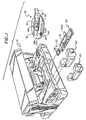
- Fig. 1 illustrates the general assembly of major components of a stamper 10 into a print engine 20. These include in a preferred embodiment a daisy character wheel and casing 30 and a character wheel foil tape cartridge 40. Alternatively, a logo frame 51 mounting a logo die 52 and a logo die foil tape cartridge 60 is employed, when a logo or other large indicia is to be printed. A logo loader-unloader tool 50 is utilized to insert and remove the logo frame and die into an entrance/port 22 at the bottom of the print engine by angular manipulation of a loader logo frame-holding loader pad 53 and a loader handle 54.
- the character wheel tape cartridge 40 is inserted into a side entrance 23 of the print engine when the character wheel and casing 30 has been or is to be inserted into the entrance 21 at the bottom of the print engine.
- Suitable latches 23a latch the respective cartridges 40 or 60 into entrance 23.
- the character wheel and casing includes a pair of spaced parallel guide rails 31 and slots 31d which interfit with corresponding slots and rails in the print engine, an insertion handle 32, a series, typically from 70-90, of radial spring fingers 33 each mounting a character-containing pad 33a at its radial end and each extending from a wheel hub 34.
- Hub 34 and its integral character wheel is driven by a stepper motor in the print engine by a motor drive pin guided by a circular arc entrance ramp on the hub top surface into a rectangular drive and homing slot 35 in the hub.
- the character wheel and casing is removed from the print engine by initial movement of handle 32.
- the top surface of the casing includes a strike window 145 and a casing window 143 for optical access of an optical sensor to sense alternating reflective and non-reflective surfaces 134 on the character wheel indicating homing of the print wheel and indicating the presence and identification code of the print wheel.
- the bottom surface includes a radial triangular slit 146 for depressed character finger passage.
- Each finger pad 33a includes a triangular ridge 138 on its top surface for character centering.
- a workpiece such as a report cover is clamped onto the platen table which moves above the base anvil (X-axis) and provides character-to-character spacing.
- the platen moves either toward or away from the operator front position.
- the carriage moves along the top guide rail and provides line-to-line spacing (Y-axis).
- the carriage moves in left to right or right to left with respect to the operator front position.
- the stamper In a typical size the stamper has a 56 cm by 38 cm 22" by 15" footprint, a 28 cm (11") height, weights about 27.3 kg (60 pounds) and a character printing speed of approximately one character per second.
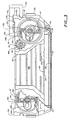
- Figs. 2 - 5 illustrate the foil cartridges 40 and 60 of the invention.
- Each of the dual cartridges includes a casing 43.
- the cartridges 40 and 60 differ in two main ways, namely, the width of the foil tape is wide, typically (1.75 inch) 4.45 cm in the logo die cartridge 60 while the foil tape width, typically 1.91 cm (0.75 inch) in the character wheel foil tape cartridge 40 is narrower. Accordingly the cartridge casing in the logo die cartridge 60 is wider as seen in Fig. 1.
- Arched strike window 42 and 42a forming a casing side indentation 42c provide for access of the character wheel forcer (or die forcer when that debossment die mode of operation is being utilized) and allows the forcer(s) heated hammer(s) to strike the top of the foil tape centrally positioned in the window 42 so that the tape transfer medium on the tape bottom is debossed into the workpiece surface.
- An outer peripheral bevel 32b is provided on the underside of the print wheel casing, particularly adjacent to the underside strike window 146 so that the insertion of the casing into the cartridge indentation 42 or vice versa does not cause snagging of the tape extending across the respective bottom strike windows.
- the indentation includes a horizontal rib 43t under which a peripheral edge of print wheel casing at the casing strike windows is inserted or vice versa.
- the peripheral exterior of the sloped bottom edges 32b of the print wheel casing on either side of the lower strike window 146 abuts rib 43r.
- the central portion of the indentation 42c and ribs 43t and 43r form a recess 42v to receive the strike windows portion of the print wheel casing.
- a supply spool 44 includes a sinuous anti-back rotation spring 44a having a central bight 44e portion extending partially around the spool or reel shaft and intermediate portions extending between a pair of cross-pieces comprising spaced fixed posts 44b and fixed angles 44c between the front and rear sides of the casing.
- the spring has distal ends 44d terminating at a position abutting in friction contact the spool circular interior surfaces. This provides a friction, preventing free-wheeling and back rotation of the supply reel 44.
- a take-up spool 45 includes a similar anti-back rotation spring 45a, and similar posts 45b and angles 45c.
- a gear 46 is attached to the tape-up spool and driven about shaft 47.
- Gear 46 is driven by gear 48 which has a spike-rear opening 49a.
- the spike opening engages a blade-ended drive shaft of the cartridge stepper-motor 40b.
- the blade is spring-loaded so it will clutch engage the spike opening as it begins to drive.
- the tape 41 from the supply spool 44 passes around a pair of fixed guide pins or rollers 62 and around an idler roller 63.
- a finger notched thumb wheel 49 accessible at the top front edge of the cartridge can be employed to tighten the ribbon before entry of the cartridge into the print engine entrance 23.
- a series, preferably four, of 90° reflector pads 64 are provided on the supply spool along with a spool sensor 105 for detecting tape jamming, broken tape or a "tape running out" condition.
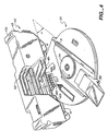
- Opposed notches 43a guide the cartridge into corresponding spaced parallel ridges 24a on the print engine.
- the notches 75a in the casting 75 and ridges on the engine housing 24 can be at different levels or spacing (such as phantom ridge 43d and notch 75b in Fig. 3) or different sizes dependent on the stamper model.
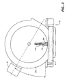
- Figs 4 and 5 illustrate the relationship between the inserted tape cartridge 40 and print wheel and casing 30 where the aligned strike windows 145 and 146, the latter in the casing bottom, are themselves aligned in the cartridge indentation 42c at a level below cartridge rib 43t.
- the cartridge is inserted linearly along one side of the print engine (Fig. 1) as guided by top projections 43c and grooves 43a on the cartridge.
- the print wheel and casing is inserted linearly from the front of the print engine as guided by guides 31.
- the included angle a between the longitudinal axis of guides 31 subtend an arc of about 30°. This orientation may be in the range of 25° and 35°, dependent on the exact location of the print wheel strike windows and the print wheel handle and guide rails 31.
- the character forcer passes down through the cartridge indentation 42c so that it forces the fingers 33 (or logo 52) against the tape 41 under the inserted print wheel casing 30.
Abstract
Description
- Fig. 1
- an exploded perspective view of a stamper showing the entry ports for the character wheel and casing, the logo and frame and logo loader/unloader and either the character transfer foil tape cartridge or logo transfer foil
- Fig. 2
- a top view of a foil tape cartridge according to the invention;
- Fig. 3
- a cutaway back view of the cartridge of Fig. 2;
- Fig. 4
- a perspective view showing the mating of the tape cartridge and the print wheel and casing; and
- Fig. 5
- a bottom plan view of the mating position of the wheel casing above the transfer tape of the cartridge of Fig. 4.
Claims (6)
- A hot stamper foil tape cartridge comprising
a generally rectangular casing (40; 60) having aligned strike windows (42; 42a) in upper and bottom sides of the casing (40; 60) and forming a casing side indentation (42c);
a first supply reel (44) journalled in said casing (40; 60);
a second take-up reel (45) journalled in said casing (40; 60);
a heat and pressure transferable foil tape (41) on said supply reel (44);
means for driving said take-up reel (45); and
means for conveying said foil tape (41) to a position between said reels (44; 45) at said bottom strike window (42; 42a)
characterized by
means including a sinous spring (44a; 45a) for preventing back rotation of at least one of said reels (44; 45) while permitting forward rotation;
wherein said reels (44; 45) include an inner peripheral surface, and
wherein said spring (44a; 45a) includes distal ends (44d; 45d) which frictional engage said surface. - A hot stamper foil tape cartridge for a hot stamper print engine, said cartridge comprising a generally rectangular casing (40; 60), said casing having aligned strike windows (42; 42a) in top and bottom edges of the casing (40; 60) forming a casing side indentation (42c),
a supply reel (44) journalled in the casing;
a take-up reel (45) journalled in the casing (40; 60); and
a heat and force transferable foil tape (41) extending between said supply reel (44) and said take-up reel (45);
wherein a portion of said tape (41) is exposed between said reels (44; 45) within said indentation (42c) adjacent to the bottom edge of the casing,
characterized by anti-back rotation springs attached to each of said reels (44; 45) which permit forward rotation. - The cartridge of claim 2, including at least one projection on a selected position on said casing (40; 60) for guiding the casing into a corresponding notch of a print engine.
- A method of heat and pressure debossing of a heat and pressure transferable media-containing tape (41) in a cartridge having a tape supply reel (44) and a tape take-up reel (45), at a first selected position on a workpiece on a platen comprising:stricking the tape (41) to deboss the transferable media into the workpiece and thenstripping a struck portion of the tape (41) from the workpiece by relative movement of the cartridge and the platen to strip a remaining part of the tape from the workpiece; and then advancing the tape take-up reel (45) to present an undebossed portion of the tape (41) above a second selected position on the workpiece, characterized in that the tape in the reels (44; 45) is holded from backing up by an anti-back rotation means.
- The method of claim 4, wherein said advancing step is variable in length based on feedback of the size of a character to be debossed by said tape (41).
- The hot stamper foil tape cartridge of claim 1, said supply reel (44) having four equally spaced reflector pads (64) disposed around its exterior periphery, at least one of said reflector pads (64) being visually accessible from the exterior of said casing (40; 60); a step motor for rotatively driving said take-up reel (45); and an optical reflective spool rotation tracking sensor (105), said sensor (105) providing feedback for calculating and indicating an amount of foil tape (41) remaining on said supply reel (44) based on the rotation of said supply reel (44) and for calculating the number of motor steps necessary to obtain a desired tape advance while compensating for a variation in the diameter of the tape on the take-up reel (45).
Applications Claiming Priority (3)
| Application Number | Priority Date | Filing Date | Title |
|---|---|---|---|
| US08/078,792 US5441589A (en) | 1993-06-17 | 1993-06-17 | Flat bed daisy wheel hot debossing stamper |
| US78792 | 1993-06-17 | ||
| PCT/US1994/006646 WO1995000339A1 (en) | 1993-06-17 | 1994-06-16 | Flat bed daisy wheel hot debossing stamper |
Publications (3)
| Publication Number | Publication Date |
|---|---|
| EP0702628A1 EP0702628A1 (en) | 1996-03-27 |
| EP0702628A4 EP0702628A4 (en) | 1996-12-27 |
| EP0702628B1 true EP0702628B1 (en) | 2002-08-28 |
Family
ID=22146257
Family Applications (1)
| Application Number | Title | Priority Date | Filing Date |
|---|---|---|---|
| EP94920176A Expired - Lifetime EP0702628B1 (en) | 1993-06-17 | 1994-06-16 | Flat bed daisy wheel hot debossing stamper |
Country Status (9)
| Country | Link |
|---|---|
| US (6) | US5441589A (en) |
| EP (1) | EP0702628B1 (en) |
| JP (1) | JPH09501363A (en) |
| AT (1) | ATE222858T1 (en) |
| CA (1) | CA2165441C (en) |
| DE (1) | DE69431248D1 (en) |
| MX (1) | MX9404598A (en) |
| TW (1) | TW252951B (en) |
| WO (1) | WO1995000339A1 (en) |
Families Citing this family (25)
| Publication number | Priority date | Publication date | Assignee | Title |
|---|---|---|---|---|
| DE19631506A1 (en) * | 1996-08-03 | 1998-02-05 | Bayerische Motoren Werke Ag | Device for the optical control of an embossing mark made with a type wheel in a workpiece by means of a camera |
| US6027265A (en) * | 1997-10-14 | 2000-02-22 | Powis Parker, Inc. | Printer having improved print head mechanism and method |
| US6065884A (en) * | 1997-10-14 | 2000-05-23 | Powis Parker, Inc. | Binder strip printer and method |
| US6203407B1 (en) | 1998-09-03 | 2001-03-20 | Micron Technology, Inc. | Method and apparatus for increasing-chemical-polishing selectivity |
| US6123471A (en) * | 1998-11-03 | 2000-09-26 | Eltron International, Inc. | Medium tracking bar |
| US6467404B1 (en) * | 2000-08-28 | 2002-10-22 | Temple Tag, Inc. | Hot stamp machine for custom imprinting plastic identifier tags |
| US6740189B1 (en) * | 2000-09-06 | 2004-05-25 | Dart Manufacturing Company | Business accessory article with graphic image and method of making |
| CN1171725C (en) * | 2000-10-25 | 2004-10-20 | 株式会社三协精机制作所 | Thermoprinting apparatus |
| US6491455B1 (en) | 2001-07-31 | 2002-12-10 | Zih Corp. | Ribbon tracking system |
| US20040125990A1 (en) * | 2002-12-26 | 2004-07-01 | Motorola, Inc. | Method and apparatus for asperity detection |
| US7126107B2 (en) | 2003-03-14 | 2006-10-24 | Lexmark International, Inc. | Methods and apparatuses for sensing rotational position of a component in a printing device |
| KR100521720B1 (en) * | 2003-11-28 | 2005-10-17 | 주식회사 이오디지텍 | a package paper thermal printer of pill packing machine |
| US7028893B2 (en) * | 2003-12-17 | 2006-04-18 | Motorola, Inc. | Fingerprint based smartcard |
| NZ532931A (en) * | 2004-05-14 | 2007-12-21 | Allflex New Zealand | Improvements in animal identification marking |
| US20060141804A1 (en) * | 2004-12-28 | 2006-06-29 | Goodman Cathryn E | Method and apparatus to facilitate electrostatic discharge resiliency |
| US7963438B2 (en) * | 2005-11-10 | 2011-06-21 | Magtek, Inc. | System and method for personalizing a card |
| US20070189587A1 (en) * | 2006-02-14 | 2007-08-16 | Garcia Carl N | Method and apparatus corresponding to an asperity detection sensor surface |
| WO2007109881A1 (en) | 2006-03-24 | 2007-10-04 | Phenomenome Discoveries Inc. | Biomarkers useful for diagnosing prostate cancer, and methods thereof |
| US20090024247A1 (en) * | 2007-07-20 | 2009-01-22 | Christopher Scott Lovchik | Slip sensor |
| US8192098B1 (en) | 2008-06-17 | 2012-06-05 | Stalsen LLC | Automatically loading printing device and method of printing |
| JP5345099B2 (en) * | 2010-04-09 | 2013-11-20 | 矢崎総業株式会社 | Instrument unit |
| US20130337102A1 (en) * | 2012-06-14 | 2013-12-19 | Massachusetts Institute Of Technology | Embossing Press |
| WO2015185084A1 (en) * | 2014-06-02 | 2015-12-10 | Hewlett-Packard Development Company, L.P. | Media handling system assembly |
| CN107000426B (en) * | 2014-11-21 | 2019-10-01 | 鲍勃斯脱梅克斯股份有限公司 | For imprinting the support system, uncoiling mould group, the assembly method of marking press and reel of foil reel |
| CN106319185A (en) * | 2015-06-29 | 2017-01-11 | 南通市嘉业机械制造有限公司 | Heat treatment processing technology of plug |
Citations (1)
| Publication number | Priority date | Publication date | Assignee | Title |
|---|---|---|---|---|
| US4210296A (en) * | 1978-12-26 | 1980-07-01 | Royal Business Machines, Inc. | Ribbon cartridge with integral anti spool rotation device |
Family Cites Families (55)
| Publication number | Priority date | Publication date | Assignee | Title |
|---|---|---|---|---|
| US1406537A (en) * | 1922-02-14 | Machine foe masking- articles | ||
| US2734614A (en) * | 1956-02-14 | Proportional ribbon feed mechanism | ||
| US1979640A (en) * | 1933-07-27 | 1934-11-06 | Roberts Cushman & Company | Marking, printing, and embossing machine |
| US3301370A (en) * | 1965-03-18 | 1967-01-31 | Miller John Dawson | Device for hot stamping indicia on webs |
| US3916783A (en) * | 1972-09-13 | 1975-11-04 | Texmark Inc | Automatic sequential textile marking machine |
| DE2442688C2 (en) * | 1974-09-06 | 1982-06-16 | Siemens AG, 1000 Berlin und 8000 München | Arrangement for scanning a disk-shaped type carrier |
| NZ176915A (en) * | 1975-03-12 | 1978-07-10 | Delta Plastics Ltd | Printing mechanism for plastics:automatically changing type |
| US4037532A (en) * | 1976-03-08 | 1977-07-26 | Xerox Corporation | Hammer assembly |
| IT1070333B (en) * | 1976-04-21 | 1985-03-29 | Olivetti & Co Spa | SERIAL PRINTER PARTICULARLY FOR SILENT ELECTRICAL WRITING MACHINES |
| US4074798A (en) * | 1976-09-01 | 1978-02-21 | Xerox Corporation | Encoded print wheel system |
| US4128346A (en) * | 1977-05-11 | 1978-12-05 | Periphonics Corporation | Daisy type print wheel apparatus |
| GB1604577A (en) * | 1977-09-14 | 1981-12-09 | Exxon Research Engineering Co | Coded printing element and apparatus for use thereof |
| DE2822313C2 (en) * | 1978-05-22 | 1985-07-04 | Olympia Werke Ag, 2940 Wilhelmshaven | Character wheel cassette for typewriters or similar office machines |
| IT1159898B (en) * | 1978-07-13 | 1987-03-04 | Olivetti & Co Spa | PRINTING DEVICE FOR WRITING MACHINE OR SIMILAR OFFICE MACHINES |
| US4319850A (en) * | 1979-07-30 | 1982-03-16 | Exxon Research & Engineering Co. | Method and means for storing typing ribbon |
| US4290704A (en) * | 1979-11-09 | 1981-09-22 | Exxon Research & Engineering Co. | Flexible ribbon guide means |
| US4373436A (en) * | 1980-06-11 | 1983-02-15 | Norwood Marking & Equipment Co., Inc. | Axially aligned driving cam imprinter |
| US4347008A (en) * | 1980-06-27 | 1982-08-31 | International Business Machines Corporation | Anti-reversal backcheck for printer ribbon cartridge takeup spool |
| JPS57163587A (en) * | 1981-03-31 | 1982-10-07 | Ricoh Co Ltd | Typewheel position controller |
| US4462708A (en) * | 1981-04-09 | 1984-07-31 | Kroy Inc. | Automated tape lettering machine |
| US4479730A (en) * | 1981-06-05 | 1984-10-30 | Ricoh Company, Ltd. | Ribbon cartridge |
| JPS58175934U (en) * | 1982-05-18 | 1983-11-25 | 株式会社サト− | thermal printing device |
| US4416199A (en) * | 1982-09-01 | 1983-11-22 | Norwood Marking & Equipment Co., Inc. | Multicolor imprinter |
| US4507668A (en) * | 1982-10-04 | 1985-03-26 | Tokyo Electric Company, Ltd. | Thermal printer |
| JPS5999759U (en) * | 1982-11-20 | 1984-07-05 | ブラザー工業株式会社 | ribbon cassette |
| DE3244665A1 (en) * | 1982-12-02 | 1984-06-07 | Siemens AG, 1000 Berlin und 8000 München | Ink ribbon cartridge with ribbon brake |
| US4516493A (en) * | 1983-02-10 | 1985-05-14 | Harold Schemenauer | Apparatus for imprinting and cutting a tape or ribbon |
| GB2135246B (en) * | 1983-02-23 | 1987-05-13 | Ricoh Kk | Daisy wheel supporting structure |
| US4541746A (en) * | 1983-10-14 | 1985-09-17 | International Business Machines Corporation | Initializing apparatus for daisy wheel printer |
| JPS60107350A (en) * | 1983-11-16 | 1985-06-12 | Ricoh Co Ltd | Printing system |
| GB8400177D0 (en) * | 1984-01-05 | 1984-02-08 | Bowthorpe Hellermann Ltd | Marking machine |
| US4544289A (en) * | 1984-01-20 | 1985-10-01 | Varitronic Systems, Inc. | Print disk positioning system |
| JPS61137748A (en) * | 1984-12-10 | 1986-06-25 | Canon Inc | Apparatus for discriminating type wheel |
| JPS61195863A (en) * | 1985-02-25 | 1986-08-30 | Tokyo Electric Co Ltd | Measuring printer |
| JPS61211071A (en) * | 1985-03-18 | 1986-09-19 | Canon Inc | Output device |
| JPS61215080A (en) * | 1985-03-20 | 1986-09-24 | Brother Ind Ltd | Printing apparatus |
| JPS61228979A (en) * | 1985-04-03 | 1986-10-13 | Nec Corp | Ink ribbon feeding system |
| JPS61248773A (en) * | 1985-04-26 | 1986-11-06 | Canon Inc | Ink ribbon cassette |
| US4790677A (en) * | 1985-10-03 | 1988-12-13 | Primages, Inc. | Method and apparatus for determining halt of tape feed in a tape cartridge for a printer |
| DE3606545C1 (en) * | 1986-02-28 | 1987-04-16 | Triumph Adler Ag | Device for coupling a type wheel with a rotary adjusting shaft in typewriters or similar machines |
| JPH0698749B2 (en) * | 1986-04-10 | 1994-12-07 | キヤノン株式会社 | Printer |
| KR960003354B1 (en) * | 1986-04-24 | 1996-03-08 | 타우러스 임프레션스 인코오포레이티드 | Book cover serial stamp printer |
| US4970531A (en) * | 1987-02-13 | 1990-11-13 | Hitachi, Ltd. | Thermal transfer printer |
| DE8713034U1 (en) * | 1987-09-28 | 1987-11-19 | Computer Gesellschaft Konstanz Mbh, 7750 Konstanz, De | |
| JPH01137231U (en) * | 1988-03-05 | 1989-09-20 | ||
| KR910005891B1 (en) * | 1988-05-31 | 1991-08-06 | 주식회사 금성사 | Carriage of electronic typewriter |
| US5087137A (en) * | 1988-07-19 | 1992-02-11 | Datamax Corporation | Ribbon assembly including indicia to identify operating parameters and ribbon depletion |
| JP2749075B2 (en) * | 1988-10-03 | 1998-05-13 | 株式会社日立製作所 | Thermal transfer recording device and ink paper cassette |
| US5026181A (en) * | 1988-10-26 | 1991-06-25 | Samsung Electronics Co., Ltd. | Ribbon cartridge for an electronic typewriter |
| US5044795A (en) * | 1989-08-30 | 1991-09-03 | Pelikan, Inc. | Wrap brake spring for the take-off core of an inked ribbon cartridge |
| JPH0544538U (en) * | 1991-11-20 | 1993-06-15 | ブラザー工業株式会社 | Printer |
| KR970003666B1 (en) * | 1991-11-21 | 1997-03-20 | 삼성전자 주식회사 | Display apparatus of remained ribbon for a printer |
| JP3097299B2 (en) * | 1992-04-20 | 2000-10-10 | ソニー株式会社 | Ink ribbon cassette type determination method and printer |
| US5318660A (en) * | 1992-05-01 | 1994-06-07 | Kensol-Olsenmark, Inc. | Method and apparatus for generating hot stamped single and multi-color images |
| US5486254A (en) * | 1993-01-21 | 1996-01-23 | Total Register, Inc. | Dual drive registration system |
-
1993
- 1993-06-17 US US08/078,792 patent/US5441589A/en not_active Expired - Lifetime
- 1993-06-18 TW TW082104862A patent/TW252951B/zh not_active IP Right Cessation
- 1993-08-05 US US08/102,601 patent/US5413422A/en not_active Expired - Fee Related
-
1994
- 1994-06-16 AT AT94920176T patent/ATE222858T1/en not_active IP Right Cessation
- 1994-06-16 DE DE69431248T patent/DE69431248D1/en not_active Expired - Lifetime
- 1994-06-16 WO PCT/US1994/006646 patent/WO1995000339A1/en active IP Right Grant
- 1994-06-16 EP EP94920176A patent/EP0702628B1/en not_active Expired - Lifetime
- 1994-06-16 CA CA002165441A patent/CA2165441C/en not_active Expired - Fee Related
- 1994-06-16 JP JP7502901A patent/JPH09501363A/en active Pending
- 1994-06-17 MX MX9404598A patent/MX9404598A/en not_active IP Right Cessation
-
1995
- 1995-05-23 US US08/449,515 patent/US5738449A/en not_active Expired - Fee Related
- 1995-05-25 US US08/452,604 patent/US5665193A/en not_active Expired - Fee Related
- 1995-05-31 US US08/456,580 patent/US5664894A/en not_active Expired - Fee Related
-
1998
- 1998-04-13 US US09/059,598 patent/US6149326A/en not_active Expired - Fee Related
Patent Citations (1)
| Publication number | Priority date | Publication date | Assignee | Title |
|---|---|---|---|---|
| US4210296A (en) * | 1978-12-26 | 1980-07-01 | Royal Business Machines, Inc. | Ribbon cartridge with integral anti spool rotation device |
Also Published As
| Publication number | Publication date |
|---|---|
| WO1995000339A1 (en) | 1995-01-05 |
| DE69431248D1 (en) | 2002-10-02 |
| AU693455B2 (en) | 1998-07-02 |
| US5441589A (en) | 1995-08-15 |
| US5413422A (en) | 1995-05-09 |
| AU7106594A (en) | 1995-01-17 |
| EP0702628A4 (en) | 1996-12-27 |
| EP0702628A1 (en) | 1996-03-27 |
| JPH09501363A (en) | 1997-02-10 |
| US5664894A (en) | 1997-09-09 |
| ATE222858T1 (en) | 2002-09-15 |
| TW252951B (en) | 1995-08-01 |
| US5738449A (en) | 1998-04-14 |
| US5665193A (en) | 1997-09-09 |
| MX9404598A (en) | 1995-01-31 |
| CA2165441A1 (en) | 1995-01-05 |
| US6149326A (en) | 2000-11-21 |
| CA2165441C (en) | 2002-04-30 |
Similar Documents
| Publication | Publication Date | Title |
|---|---|---|
| EP0702628B1 (en) | Flat bed daisy wheel hot debossing stamper | |
| EP0327076B1 (en) | Tape supply system for a thermal printing device or the like | |
| EP0661163B1 (en) | Label printer and tape and ink ribbon cartridge for use therein | |
| USRE43185E1 (en) | Tape cassette for use with a printing device | |
| EP0327073B1 (en) | Thermal printing device and tape supply cartridge therefor | |
| US5056940A (en) | Thermal printing device and tape supply cartridge therefor | |
| US4815874A (en) | Thermal printer and tape-ribbon cartridge with cut-off mechanism | |
| CA1098833A (en) | Impact printer with print wheel cartridge | |
| EP0327075A2 (en) | Thermal printing device and tape supply cartridge embodying a tape cut-off mechanism | |
| EP0141412A2 (en) | Tape supply cartridge | |
| US4832514A (en) | Thermal transfer device and tape-ribbon cartridge therefor | |
| JPH11116108A (en) | Recording device | |
| US6224276B1 (en) | Ink ribbon cartridge including ink ribbon damaging means and rotation direction restricting means | |
| EP1066973B1 (en) | Printer and spool | |
| US4983055A (en) | Type wheel supporting structure | |
| EP0023806A2 (en) | Ribbon supply and printing apparatus with a flexible ribbon leader, and method of forming such a flexible ribbon leader | |
| US3728963A (en) | Ribbon feed cartridge | |
| US5529409A (en) | Ribbon cartridge for a compact remote-driven encoder | |
| US5037222A (en) | Printer and cartridge assembly therefor | |
| US4289413A (en) | Cartridge and ribbon for use with a single spool stenotype machine | |
| AU693455C (en) | Hot stamper foil tape cartridge | |
| EP0204556B1 (en) | Imprinter apparatus | |
| EP1405730B1 (en) | Thermal printer | |
| EP0142108A2 (en) | Tape-ribbon cartridge | |
| JP2551524Y2 (en) | Cutter device |
Legal Events
| Date | Code | Title | Description |
|---|---|---|---|
| PUAI | Public reference made under article 153(3) epc to a published international application that has entered the european phase |
Free format text: ORIGINAL CODE: 0009012 |
|
| 17P | Request for examination filed |
Effective date: 19960117 |
|
| AK | Designated contracting states |
Kind code of ref document: A1 Designated state(s): AT BE CH DE ES FR GB IE IT LI LU |
|
| A4 | Supplementary search report drawn up and despatched |
Effective date: 19961108 |
|
| AK | Designated contracting states |
Kind code of ref document: A4 Designated state(s): AT BE CH DE ES FR GB IE IT LI LU |
|
| 17Q | First examination report despatched |
Effective date: 19980217 |
|
| GRAG | Despatch of communication of intention to grant |
Free format text: ORIGINAL CODE: EPIDOS AGRA |
|
| GRAG | Despatch of communication of intention to grant |
Free format text: ORIGINAL CODE: EPIDOS AGRA |
|
| GRAH | Despatch of communication of intention to grant a patent |
Free format text: ORIGINAL CODE: EPIDOS IGRA |
|
| GRAH | Despatch of communication of intention to grant a patent |
Free format text: ORIGINAL CODE: EPIDOS IGRA |
|
| GRAA | (expected) grant |
Free format text: ORIGINAL CODE: 0009210 |
|
| AK | Designated contracting states |
Kind code of ref document: B1 Designated state(s): AT BE CH DE ES FR GB IE IT LI LU |
|
| PG25 | Lapsed in a contracting state [announced via postgrant information from national office to epo] |
Ref country code: LI Free format text: LAPSE BECAUSE OF FAILURE TO SUBMIT A TRANSLATION OF THE DESCRIPTION OR TO PAY THE FEE WITHIN THE PRESCRIBED TIME-LIMIT Effective date: 20020828 Ref country code: IT Free format text: LAPSE BECAUSE OF FAILURE TO SUBMIT A TRANSLATION OF THE DESCRIPTION OR TO PAY THE FEE WITHIN THE PRE;WARNING: LAPSES OF ITALIAN PATENTS WITH EFFECTIVE DATE BEFORE 2007 MAY HAVE OCCURRED AT ANY TIME BEFORE 2007. THE CORRECT EFFECTIVE DATE MAY BE DIFFERENT FROM THE ONE RECORDED.SCRIBED TIME-LIMIT Effective date: 20020828 Ref country code: FR Free format text: LAPSE BECAUSE OF NON-PAYMENT OF DUE FEES Effective date: 20020828 Ref country code: CH Free format text: LAPSE BECAUSE OF FAILURE TO SUBMIT A TRANSLATION OF THE DESCRIPTION OR TO PAY THE FEE WITHIN THE PRESCRIBED TIME-LIMIT Effective date: 20020828 Ref country code: BE Free format text: LAPSE BECAUSE OF FAILURE TO SUBMIT A TRANSLATION OF THE DESCRIPTION OR TO PAY THE FEE WITHIN THE PRESCRIBED TIME-LIMIT Effective date: 20020828 Ref country code: AT Free format text: LAPSE BECAUSE OF FAILURE TO SUBMIT A TRANSLATION OF THE DESCRIPTION OR TO PAY THE FEE WITHIN THE PRESCRIBED TIME-LIMIT Effective date: 20020828 |
|
| REF | Corresponds to: |
Ref document number: 222858 Country of ref document: AT Date of ref document: 20020915 Kind code of ref document: T |
|
| REG | Reference to a national code |
Ref country code: GB Ref legal event code: FG4D |
|
| REG | Reference to a national code |
Ref country code: CH Ref legal event code: EP |
|
| REF | Corresponds to: |
Ref document number: 69431248 Country of ref document: DE Date of ref document: 20021002 |
|
| REG | Reference to a national code |
Ref country code: IE Ref legal event code: FG4D |
|
| PG25 | Lapsed in a contracting state [announced via postgrant information from national office to epo] |
Ref country code: DE Free format text: LAPSE BECAUSE OF FAILURE TO SUBMIT A TRANSLATION OF THE DESCRIPTION OR TO PAY THE FEE WITHIN THE PRESCRIBED TIME-LIMIT Effective date: 20021129 |
|
| PG25 | Lapsed in a contracting state [announced via postgrant information from national office to epo] |
Ref country code: ES Free format text: LAPSE BECAUSE OF FAILURE TO SUBMIT A TRANSLATION OF THE DESCRIPTION OR TO PAY THE FEE WITHIN THE PRESCRIBED TIME-LIMIT Effective date: 20030228 |
|
| REG | Reference to a national code |
Ref country code: CH Ref legal event code: PL |
|
| PG25 | Lapsed in a contracting state [announced via postgrant information from national office to epo] |
Ref country code: LU Free format text: LAPSE BECAUSE OF NON-PAYMENT OF DUE FEES Effective date: 20030616 |
|
| EN | Fr: translation not filed | ||
| PLBE | No opposition filed within time limit |
Free format text: ORIGINAL CODE: 0009261 |
|
| STAA | Information on the status of an ep patent application or granted ep patent |
Free format text: STATUS: NO OPPOSITION FILED WITHIN TIME LIMIT |
|
| 26N | No opposition filed |
Effective date: 20030530 |
|
| PGFP | Annual fee paid to national office [announced via postgrant information from national office to epo] |
Ref country code: IE Payment date: 20070626 Year of fee payment: 14 |
|
| PGFP | Annual fee paid to national office [announced via postgrant information from national office to epo] |
Ref country code: GB Payment date: 20070628 Year of fee payment: 14 |
|
| GBPC | Gb: european patent ceased through non-payment of renewal fee |
Effective date: 20080616 |
|
| REG | Reference to a national code |
Ref country code: IE Ref legal event code: MM4A |
|
| PG25 | Lapsed in a contracting state [announced via postgrant information from national office to epo] |
Ref country code: IE Free format text: LAPSE BECAUSE OF NON-PAYMENT OF DUE FEES Effective date: 20080616 |
|
| PG25 | Lapsed in a contracting state [announced via postgrant information from national office to epo] |
Ref country code: GB Free format text: LAPSE BECAUSE OF NON-PAYMENT OF DUE FEES Effective date: 20080616 |