EP0702142A1 - Pump unit incorporating a pressure regulator, for automotive fuel tank and tank so equipped - Google Patents
Pump unit incorporating a pressure regulator, for automotive fuel tank and tank so equipped Download PDFInfo
- Publication number
- EP0702142A1 EP0702142A1 EP95402079A EP95402079A EP0702142A1 EP 0702142 A1 EP0702142 A1 EP 0702142A1 EP 95402079 A EP95402079 A EP 95402079A EP 95402079 A EP95402079 A EP 95402079A EP 0702142 A1 EP0702142 A1 EP 0702142A1
- Authority
- EP
- European Patent Office
- Prior art keywords
- filter
- pump
- regulator
- outlet
- tank
- Prior art date
- Legal status (The legal status is an assumption and is not a legal conclusion. Google has not performed a legal analysis and makes no representation as to the accuracy of the status listed.)
- Granted
Links
Images


Classifications
-
- F—MECHANICAL ENGINEERING; LIGHTING; HEATING; WEAPONS; BLASTING
- F02—COMBUSTION ENGINES; HOT-GAS OR COMBUSTION-PRODUCT ENGINE PLANTS
- F02M—SUPPLYING COMBUSTION ENGINES IN GENERAL WITH COMBUSTIBLE MIXTURES OR CONSTITUENTS THEREOF
- F02M37/00—Apparatus or systems for feeding liquid fuel from storage containers to carburettors or fuel-injection apparatus; Arrangements for purifying liquid fuel specially adapted for, or arranged on, internal-combustion engines
- F02M37/0011—Constructional details; Manufacturing or assembly of elements of fuel systems; Materials therefor
- F02M37/0023—Valves in the fuel supply and return system
- F02M37/0029—Pressure regulator in the low pressure fuel system
-
- F—MECHANICAL ENGINEERING; LIGHTING; HEATING; WEAPONS; BLASTING
- F02—COMBUSTION ENGINES; HOT-GAS OR COMBUSTION-PRODUCT ENGINE PLANTS
- F02M—SUPPLYING COMBUSTION ENGINES IN GENERAL WITH COMBUSTIBLE MIXTURES OR CONSTITUENTS THEREOF
- F02M37/00—Apparatus or systems for feeding liquid fuel from storage containers to carburettors or fuel-injection apparatus; Arrangements for purifying liquid fuel specially adapted for, or arranged on, internal-combustion engines
- F02M37/0076—Details of the fuel feeding system related to the fuel tank
- F02M37/0082—Devices inside the fuel tank other than fuel pumps or filters
-
- F—MECHANICAL ENGINEERING; LIGHTING; HEATING; WEAPONS; BLASTING
- F02—COMBUSTION ENGINES; HOT-GAS OR COMBUSTION-PRODUCT ENGINE PLANTS
- F02M—SUPPLYING COMBUSTION ENGINES IN GENERAL WITH COMBUSTIBLE MIXTURES OR CONSTITUENTS THEREOF
- F02M37/00—Apparatus or systems for feeding liquid fuel from storage containers to carburettors or fuel-injection apparatus; Arrangements for purifying liquid fuel specially adapted for, or arranged on, internal-combustion engines
- F02M37/04—Feeding by means of driven pumps
- F02M37/08—Feeding by means of driven pumps electrically driven
- F02M37/10—Feeding by means of driven pumps electrically driven submerged in fuel, e.g. in reservoir
- F02M37/106—Feeding by means of driven pumps electrically driven submerged in fuel, e.g. in reservoir the pump being installed in a sub-tank
-
- F—MECHANICAL ENGINEERING; LIGHTING; HEATING; WEAPONS; BLASTING
- F02—COMBUSTION ENGINES; HOT-GAS OR COMBUSTION-PRODUCT ENGINE PLANTS
- F02M—SUPPLYING COMBUSTION ENGINES IN GENERAL WITH COMBUSTIBLE MIXTURES OR CONSTITUENTS THEREOF
- F02M37/00—Apparatus or systems for feeding liquid fuel from storage containers to carburettors or fuel-injection apparatus; Arrangements for purifying liquid fuel specially adapted for, or arranged on, internal-combustion engines
- F02M37/22—Arrangements for purifying liquid fuel specially adapted for, or arranged on, internal-combustion engines, e.g. arrangements in the feeding system
- F02M37/32—Arrangements for purifying liquid fuel specially adapted for, or arranged on, internal-combustion engines, e.g. arrangements in the feeding system characterised by filters or filter arrangements
- F02M37/44—Filters structurally associated with pumps
-
- F—MECHANICAL ENGINEERING; LIGHTING; HEATING; WEAPONS; BLASTING
- F02—COMBUSTION ENGINES; HOT-GAS OR COMBUSTION-PRODUCT ENGINE PLANTS
- F02M—SUPPLYING COMBUSTION ENGINES IN GENERAL WITH COMBUSTIBLE MIXTURES OR CONSTITUENTS THEREOF
- F02M37/00—Apparatus or systems for feeding liquid fuel from storage containers to carburettors or fuel-injection apparatus; Arrangements for purifying liquid fuel specially adapted for, or arranged on, internal-combustion engines
- F02M37/22—Arrangements for purifying liquid fuel specially adapted for, or arranged on, internal-combustion engines, e.g. arrangements in the feeding system
- F02M37/32—Arrangements for purifying liquid fuel specially adapted for, or arranged on, internal-combustion engines, e.g. arrangements in the feeding system characterised by filters or filter arrangements
- F02M37/46—Filters structurally associated with pressure regulators
-
- F—MECHANICAL ENGINEERING; LIGHTING; HEATING; WEAPONS; BLASTING
- F02—COMBUSTION ENGINES; HOT-GAS OR COMBUSTION-PRODUCT ENGINE PLANTS
- F02M—SUPPLYING COMBUSTION ENGINES IN GENERAL WITH COMBUSTIBLE MIXTURES OR CONSTITUENTS THEREOF
- F02M37/00—Apparatus or systems for feeding liquid fuel from storage containers to carburettors or fuel-injection apparatus; Arrangements for purifying liquid fuel specially adapted for, or arranged on, internal-combustion engines
- F02M37/22—Arrangements for purifying liquid fuel specially adapted for, or arranged on, internal-combustion engines, e.g. arrangements in the feeding system
- F02M37/32—Arrangements for purifying liquid fuel specially adapted for, or arranged on, internal-combustion engines, e.g. arrangements in the feeding system characterised by filters or filter arrangements
- F02M37/50—Filters arranged in or on fuel tanks
Definitions
- the present invention relates to the field of fuel supply devices for internal combustion engines on motor vehicles.
- the conventional fuel supply systems for internal combustion engines comprise a pump 10 which takes the fuel from a tank 12, and directs this fuel to the area of use, for example the injectors or the intake manifold 14, via a supply pipe 16.
- the excess fuel is returned to the tank 12 using a return pipe 18.
- the pump 10 generally comprises a filter upstream 11.
- a downstream filter 13 is generally placed at the outlet of the pump 10, on the supply pipe 16.
- This conventional arrangement known as a loop, shown in FIG. 1, has the drawback of leading to a heating of the fuel passing through the zone of use 14 and brought back to the tank 12 by the return duct 18.
- a pressure regulator 20 is preferably integrated on the supply line 16. This pressure regulator 20 ensures the return of the excess fuel, to the tank 12.
- This pressure regulator 20 has its inlet connected to the supply line 16, generally downstream of the filter 13, by a bypass duct 15. The outlet of the regulator 20 opens into the tank 12.
- the outlet of the pump 106 is connected to the inlet of the filter 13 outside the reservoir, via the conduit 102.
- the outlet of the filter 13 is connected to the injectors 14. It is also connected to the inlet of the regulator 20, via the conduit 103, which is connected to the bypass conduit 15 shown in FIG. 2.
- Document US-A-5078167 describes a variant according to which the drawing assembly comprises a fixing base designed to be fixed on the wall of a fuel tank, a pump, a supply duct connected to the outlet of the pump, a filter placed on this supply pipe and a pressure regulator associated with the pump, placed between the pump outlet and the filter inlet, the pressure regulator and the filter being fixed on the base of the The drawing assembly and the pressure regulator being supported by the filter housing.
- the present invention now aims to improve the existing fuel supply devices.
- a device for supplying fuel to an internal combustion engine of the type comprising a drawing assembly comprising a fixing base designed to be fixed to the wall of a fuel tank, a pump , at least one supply duct connected to the pump outlet, a filter placed on this supply duct and a pressure regulator associated with the pump, the pressure regulator and the filter being fixed on the base of the drawing assembly, and the pressure regulator being supported by the filter housing, characterized in that the pressure regulator is placed downstream of the filter and the filter comprises a filter structure in the shape of a crown, supplied from the outside by the pump outlet, while the pressure regulator is placed in the central part of the filter structure.
- the invention also relates to the fuel tanks thus equipped.
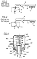
- This device is designed to be placed in a motor vehicle fuel tank, which is only partially represented in the appended FIG. 4, with the general reference R.
- the device 200 comprises a base 210 which supports a drawing assembly essentially comprising a pump 220, a filter 250 and a pressure regulator 300.
- the base 210 is adapted to be fixed on the upper wall R1 of the reservoir R, opposite an access orifice formed therein.
- the base 210 is preferably made of plastic. Its geometry can be the subject of numerous variants. It is preferably generally circular, centered around a vertical axis.
- the base 210 can be fixed to the upper wall R1 of the tank by any suitable means. It is preferably a removable mounting.
- the base 210 is advantageously fixed by means of a ring maintained by screwing or locking with the interposition of an annular seal, on the upper wall R1 of the reservoir R.
- the base 210 serves as a support for a fuel outlet pipe 212.
- the base 210 also serves as a support for electrical connections 214. These electrical connections, schematically represented in FIG. 4, are intended to allow, of a on the one hand the supply of the pump 220, on the other hand the establishment of an electrical connection with a gauging device 400, preferably equipping the drawing assembly 200.
- connections 214 can be the subject of numerous variants. Their number depends on the nature of the gauging means 400 and on the pump 220 used.
- the base 210 is molded onto these connections 214.
- the upper base 210 is provided with an underlying mount 216, preferably formed of a cylindrical barrel, adapted to support the drawing assembly 200.
- the pump 220 can be the subject of numerous variant embodiments. It is preferably a conventional electrically controlled pump.
- the pump 220 is advantageously placed in a bowl 240 serving as a fuel reserve, connected by its upper end to the base of the frame 216.
- the bowl 240 can thus be rigidly fixed on the frame 216.
- the bowl 240 is connected to the mount 216 by means of a telescopic assembly, so that the bowl 240 is permanently urged against the lower wall R2 of the reservoir.
- the reserve bowl 240 can be supplied itself by any suitable means, for example using a booster pump, or a pump such as a jet pump, or even using a valve. non-return valve, as shown schematically under the reference 242, in the bottom of the bowl 240, to allow the penetration of fuel from the tank R to the bowl 240 when the level of fuel in the tank R is higher than that of the fuel in the bowl 240, while on the contrary prohibiting the flow of fuel from the bowl 240 to the tank R.
- the inlet of the pump 220 is placed near the bottom of the bowl 240, that is to say near the bottom of the tank R.
- the inlet of the pump 220 is preferably provided with an upstream filter 222 adjacent to the bottom of the bowl 240.
- the outlet of the pump 220 is preferably provided with a vertical nozzle 224 tightly connected to the inlet of the filter 250.
- the filter 250 comprises a casing 252, advantageously cylindrical, placed in the mount 216, on the top of the bowl 240.
- the casing 250 can be the subject of numerous variants. It is preferably formed by assembling two cylindrical shells, made of plastic or metal.
- the housing 252 houses a filter structure 254 in the form of a crown.
- the filter structure 254 can be formed by any suitable means. It is preferably a conventional filter structure based on paper, shaped as a labyrinth for the fuel to be filtered.
- the two sides 253, 255 of the filtering structure in a crown 254 are tightly connected to the opposite walls 251 and upper 258 respectively of the housing 250.
- the outlet nozzle 224 of the pump 220 opens into the radially outer inlet chamber, 256, of the filter 250.
- the regulator 300 is placed in the internal outlet chamber 257.
- the bottom wall 251 of the filter housing 252 250 has, preferably at its center, and in the internal chamber 257, a generally cylindrical and stepped structure 260 which serves as a support for the regulator 300. More precisely, according to the particular embodiment shown in FIG. 4, this support structure 260 comprises two cylindrical sleeves 262, 264, connected by a radial recess 266.
- the sleeve 262 opens towards the bottom of the bowl 240.
- the sleeve 264 superimposed on the sleeve 262 has a larger diameter than this latest.
- the sleeve 264 also has at least one through bore 265 allowing communication between its internal volume and the internal chamber 257 of the filter 250.
- the pressure regulator 300 is placed downstream of the filter 250, more precisely of the filtering structure 254, so that it receives only filtered fuel.
- the regulated output of the regulator 300 communicates with the chamber 257.
- the output of the regulator 300 corresponding to the overflow of fuel communicates with the sleeve 262 and from there with the bowl 240.
- the upper wall 258 of the housing 252 of the filter 250 is in turn provided with an end piece 270 tightly connected to the end piece 212 carried by the base 210.
- the end piece 270 communicates with the outlet chamber 257 of the filter.
- the fuel is directed, from this nozzle 212, to the zone of use, injector (s) or carburetor (s), by any suitable conduit.
- the fuel used follows the following circuit: pump 220, external chamber 256 of the filter, filter structure 254, internal chamber 257 of the filter 250, then connection between the nozzles 270 and 212.
- Sealing means 226 are provided between the outlet 224 of the pump 220 and the inlet of the filter 250. These sealed connection means can be formed for example of a flexible tube. However, from preferably, the outlet nozzle 224 of the pump 220 is arranged in the form of a sealed telescopic mounting in the base of the radially external inlet chamber 256 of the filter 250.
- sealing means 226 can be the subject of many variations. These can be simple O-rings. However, preferably, these sealing means are formed of at least one lip seal, very preferably a seal having a cross section in V with concavity oriented axially. In other words, such a seal comprises two elastic lips inclined to one another in a V and oriented substantially parallel to the central axis of the seal.
- the means of connection between the outlet nozzle 270 of the filter 250 and the nozzle 212 carried by the base 210 can be comparable to those provided between the outlet 224 of the pump 220 and the inlet of the filter 250.
- connection between the outlet end piece 270 of the filter 250 and the end piece 212 carried by the base 210 can be ensured by a flexible conduit 272 as illustrated in FIG. 4.
- the end piece 270 can be arranged in sealed telescopic mounting in the endpiece 212 carried by the base 210, with the interposition of a seal, such as a seal with two lips having a cross section in V, as described above for the outlet of pump 220.
- the pressure regulator 300 is preferably a regulator with coaxial input / output.
- the pressure regulation function is obtained, using the regulator 300, by a bypass flow, regulated by a membrane supporting the combined action of the liquid whose pressure is regulated, and of a calibration spring.
- the regulator 300 comprises a body 302 generally cylindrical of revolution about a vertical axis 304.
- the body 302 is provided with a flange 310 or rib projecting from its outer surface, substantially at mid-height.
- the body 302 is split into two chambers by a flexible membrane 330, transverse to the axis 304.
- the external periphery of the membrane 330 is tightly fixed to the internal surface of the body 302.
- the external periphery of the membrane 330 is pinched by the body 302 at the flange 310.
- the upper chamber 332 delimited in the body 302 by the membrane 330 receives a calibration spring 340.
- the lower chamber 334 located on the other side of the membrane 330 receives a projecting tube 324, centered on the axis 304.
- This tube 324 extends on the outside of the body 302, towards the bowl 240 in the form of the tip 320 above.
- the tube 324 is tightly connected to the body 302.
- the top 325 of the internal tube 324 is located near the membrane 330, more precisely opposite a shutter 331 supported by the latter.
- the spring 340 pushes the shutter 331 against the top of the tube 320, to close the latter.
- the lower chamber 334 is connected to the outside, either with the filter outlet chamber 257, through through passages 335 formed in the body 302 at the base thereof, around the nozzle 320. From preferably, several passages are thus provided crossing 335 equi-distributed around the axis 304.
- the membrane 330 and the shutter 331 are spaced from the top of the tube 325. The fuel can then flow from the lower chamber 334 towards the end piece 320 by the tube 324, and from there join the bowl 240.
- the body 302 is provided under the collar 310 and above the passages 335, with an annular groove 306, designed to receive an annular seal 308 ensuring the seal between the body 302 and the internal surface of the sleeve 264 linked to the wall 251 of the filter housing 252.
- a second annular seal 321 seals between the outer surface of the end piece 320 and the sheath 262 in which this end piece 320 is engaged.
- the regulator 300 can be fixed on the sleeves 262, 264 linked to the housing 252 by any suitable means, for example by a ring 309 engaged with the external surface of the body 302 and with the internal surface of a third sleeve 267 linked to the second sleeve 266 by means of a recess 268.
- the base 210 is placed opposite an access and inspection hatch provided on the chassis of the vehicle. Therefore, the filter 250 is easy to access since it suffices to disassemble the base 210 to access this filter.
- the filter 250 can be replaced without difficulty in a service station road when the vehicle mileage reaches a required threshold defined by the manufacturer.
- the pump bodies 220 are immobilized in mounts, using dampers generally provided respectively in the lower part and in the upper part of the pump.
- the damper generally provided at the top of the pump is replaced by flexible connecting means.
- the regulator 300 works with an absolute reference pressure corresponding to the pressure which prevails at rest in this chamber 332.
- FIG. 5 shows an alternative embodiment according to which, as is also shown diagrammatically in FIG. 6, this upper chamber 332 of the regulator 300 has at least one through passage 303 through which the chamber 302 communicates. with an auxiliary pressure reference.
- the upper chamber 332 of the body 302 is placed in a recess 280 formed in the upper wall 258 of the housing 252.
- the seal between the outer surface of the body 302 of the regulator 300 and a sleeve 281 linked to the clearance 280 is provided by the seal 308.
- the regulator 300 is fixed in the clearance 280 by the ring 309.
- the passage 303 thus communicates with the upper part of the reservoir R.
- the regulator 300 rests by its flange 310 on a recess 282 connecting the sheath 281 and the clearance 280.
- the end piece 320 is engaged in a sheath 262 linked to the bottom wall 251 of the filter and a seal 321 seals between this end piece 320 and this scabbard 262.
- This passage 303 formed in the body 302 of the regulator 300 can in other ways be connected, by means of an appropriate conduit, to the outside of the reservoir R, to be placed at atmospheric pressure, or even at the pressure of the engine intake manifold.
- the upstream filters 108 or primary filters generally have, according to conventional installations, a filtering capacity for particles greater than 70 ⁇ m.
- the downstream filter 13 on the other hand generally has a filtering power in the range 3-10 ⁇ m.
- a filter 222 with a filtering power capable of retaining particles of the order of 20 to 30 ⁇ m.
- This arrangement allows the use of a downstream filter 250 with the same filtering powers from 3 to 10 ⁇ m as conventional installations, but with a smaller filtering surface, and consequently reducing the size of this downstream filter 250 to allow its integration on the base 210, in the tank.
- the drawing assembly 200 can be equipped, as mentioned above, with a system for gauging the level and / or volume of fuel in the tank R.
- Such a gauge equipping the pumping assembly can be in accordance with the known and marketed arrangements nowadays and essentially comprising a housing 402 fixed on the mount 216 or on the bowl 240, a resistive track placed in the housing, a float 404 capable of follow the evolutions of the fuel level and a cursor linked directly to the float or linked to it via a pivoting lever, which cursor moves on the resistive track according to the evolutions of the float.
- the gauge can also be formed from any other known structure, for example a capacitive gauge.
- the bowl 240 is mounted to slide vertically, on the base of the mount 216. If necessary, the bowl 240 can be biased against the bottom wall R2 of the tank R by simple gravity. However, preferably, at least one spring is interposed between the frame 216 and the bowl 240. Thanks to this indexing on the bottom, in a manner known per se, the bowl 240, and consequently the pump 220 as well as the gauging device associated 400, follow the bottom of the tank R2 whatever the deformations thereof, for example under the effect of the weight of the fuel, the manufacturing dispertions or even as a function of the temperature or due to the aging of the tank.
- the horizontal base 210 is fixed to the upper wall R1 of the tank.
- the base 210 can be inclined to the horizontal, or even fixed to a side wall of the tank R.
- the indexing on the bottom R2 of the tank can be obtained not by mounting telescopic in a vertical direction, but by pivoting mounting around a horizontal axis of the drawing / gauging assembly.
- the upper part of the filter housing 252 250 can be arranged directly in the form of a base provided with the outlet pipe 212.
- the ends 270 and 212 are then combined. This arrangement makes it possible to reduce the number of hydraulic connections required and also to reduce the height of the system.
- the present invention offers many advantages.
- the outer casing 290 of the filter 250 may be in the form of a cylinder of revolution locally comprising a protuberance 292 at the level of which the connection and connection means are located. sealing with outlet 224 of pump 220.
Abstract
Description
La présente invention concerne le domaine des dispositifs d'alimentation en carburant de moteurs à combustion interne sur véhicules automobiles.The present invention relates to the field of fuel supply devices for internal combustion engines on motor vehicles.
Comme représenté schématiquement sur la figure 1 annexée, les systèmes classiques d'alimentation en carburant de moteurs à combusion interne comprennent une pompe 10 qui prélève le carburant dans un réservoir 12, et dirige ce carburant vers la zone d'utilisation, par exemple les injecteurs ou le collecteur d'admission 14, par l'intermédiaire d'une tuyauterie d'alimentation 16. Le carburant en excès est retourné vers le réservoir 12 à l'aide d'une tuyauterie de retour 18. La pompe 10 comprend généralement un filtre amont 11. De plus un filtre aval 13 est généralement placé en sortie de la pompe 10, sur la tuyauterie 16 d'alimentation.As shown diagrammatically in the appended FIG. 1, the conventional fuel supply systems for internal combustion engines comprise a
Cette disposition classique, dite en boucle, représentée sur la figure 1, présente l'inconvénient de conduire à un réchauffement du carburant passant par la zone d'utilisation 14 et ramené au réservoir 12 par le conduit de retour 18.This conventional arrangement, known as a loop, shown in FIG. 1, has the drawback of leading to a heating of the fuel passing through the zone of
Pour éviter ce réchauffement du carburant et diminuer par conséquent les émissions de vapeur du carburant accumulée dans le réservoir 12, il a été proposé, comme schématisé sur la figure 2, des systèmes d'alimentation dits en cul de sac, dans lesquels la conduite de retour 18 est supprimée. Dans ce cas, comme on l'a schématisé sur la figure 2, un régulateur de pression 20 est de préférence intégré sur la conduite d'alimentation 16. Ce régulateur de pression 20 assure le retour du carburant en excès, vers le réservoir 12. Ce régulateur de pression 20 a son entrée reliée à la conduite d'alimentation 16, généralement en aval du filtre 13, par un conduit de dérivation 15. La sortie du régulateur 20 débouche dans le réservoir 12.To avoid this heating of the fuel and consequently to decrease the emissions of vapor of the fuel accumulated in the
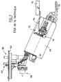
Plus précisément, comme on l'a illustré sur la figure 3, le déposant a proposé depuis plusieurs années des systèmes appliquant le principe rappelé ci-dessus et qui comprennent :
- une embase supérieure 100 conçue pour être fixée sur une paroi de réservoir,
- des
conduits - un régulateur de
pression 104, - une
pompe 106 équipée d'unfiltre 108 à son entrée et - une jauge de
niveau 110 comprenant essentiellement unflotteur 112 fixé sur un bras pivotant 114 et conçue pour contrôler, par l'intermédiaire d'un curseur, un transducteur résistif 116.
- an
upper base 100 designed to be fixed to a tank wall, -
conduits base 100, - a
pressure regulator 104, - a
pump 106 fitted with afilter 108 at its inlet and - a
level gauge 110 essentially comprising afloat 112 fixed on a pivotingarm 114 and designed to control, by means of a cursor, aresistive transducer 116.
La sortie de la pompe 106 est reliée à l'entrée du filtre 13 extérieur au réservoir, par l'intermédiaire du conduit 102. La sortie du filtre 13 est reliée aux injecteurs 14. Elle est également reliée à l'entrée du régulateur 20, par l'intermédiaire du conduit 103, lequel est raccordé au conduit de dérivation 15 représenté sur la figure 2.The outlet of the
Le montage en résultant du régulateur 104 est assez complexe.The resulting assembly of
Le document US-A-5078167 décrit une variante selon laquelle l'ensemble de puisage comprend une embase de fixation conçue pour être fixée sur la paroi d'un réservoir de carburant, une pompe, un conduit d'alimentation relié à la sortie de la pompe, un filtre placé sur ce conduit d'alimentation et un régulateur de pression associé à la pompe, placé entre la sortie de la pompe et l'entrée du filtre, le régulateur de pression et le filtre étant fixés sur l'embase de l'ensemble de puisage et le régulateur de pression étant supporté par le boîtier du filtre.Document US-A-5078167 describes a variant according to which the drawing assembly comprises a fixing base designed to be fixed on the wall of a fuel tank, a pump, a supply duct connected to the outlet of the pump, a filter placed on this supply pipe and a pressure regulator associated with the pump, placed between the pump outlet and the filter inlet, the pressure regulator and the filter being fixed on the base of the The drawing assembly and the pressure regulator being supported by the filter housing.
La disposition ainsi décrite dans le document US-A-5078167 vise essentiellement à augmenter la durée de vie du filtre, en ne filtrant que le carburant utilisé. Cependant cette disposition ne donne pas totalement satisfaction. Pour piloter le régulateur de pression avec la pression de sortie du filtre, elle impose une structure relativement complexe.The arrangement thus described in document US-A-5078167 essentially aims to increase the life of the filter, by filtering only the fuel used. However, this provision is not entirely satisfactory. To control the pressure regulator with the filter outlet pressure, it requires a relatively complex structure.
La présente invention a maintenant pour but de perfectionner les dispositifs d'alimentation en carburant existants.The present invention now aims to improve the existing fuel supply devices.
Ce but est atteint selon la présente invention grâce à un dispositif d'alimentation en carburant de moteur à combustion interne du type comportant un ensemble de puisage comprenant une embase de fixation conçue pour être fixée sur la paroi d'un réservoir de carburant, une pompe, au moins un conduit d'alimentation relié à la sortie de la pompe, un filtre placé sur ce conduit d'alimentation et un régulateur de pression associé à la pompe, le régulateur de pression et le filtre étant fixés sur l'embase de l'ensemble de puisage, et le régulateur de pression étant supporté par le boîtier du filtre, caractérisé par le fait que le régulateur de pression est placé en aval du filtre et le filtre comprend une structure filtrante en forme de couronne, alimentée, par l'extérieur, par la sortie de pompe, tandis que le régulateur de pression est placé dans la partie centrale de la structure filtrante.This object is achieved according to the present invention by a device for supplying fuel to an internal combustion engine of the type comprising a drawing assembly comprising a fixing base designed to be fixed to the wall of a fuel tank, a pump , at least one supply duct connected to the pump outlet, a filter placed on this supply duct and a pressure regulator associated with the pump, the pressure regulator and the filter being fixed on the base of the drawing assembly, and the pressure regulator being supported by the filter housing, characterized in that the pressure regulator is placed downstream of the filter and the filter comprises a filter structure in the shape of a crown, supplied from the outside by the pump outlet, while the pressure regulator is placed in the central part of the filter structure.
L'invention concerne également les réservoirs de carburant ainsi équipés.The invention also relates to the fuel tanks thus equipped.
D'autres caractéristiques, buts et avantages de la présente invention apparaîtront à la lecture de la description détaillée qui va suivre, et en regard des dessins annexés donnés à titre d'exemples non limitatifs et sur lesquels :
- les figures 1 à 3 précédemment décrites illustrent schématiquement des dispositions conformes à l'état de la technique,
- la figure 4 représente une vue schématique en coupe d'un premier exemple de réalisation conforme à la présente invention,
- la figure 5 représente une vue schématique en coupe d'un second mode de réalisation de la présente invention,
- la figure 6 représente une vue schématique en coupe axiale d'un régulateur conforme à l'invention, et
- la figure 7 représente une vue schématique partielle en coupe, selon un plan de coupe transversal référencé VII-VII sur la figure 4, d'un dispositif conforme à la présente invention.
- FIGS. 1 to 3 previously described schematically illustrate arrangements in accordance with the state of the art,
- FIG. 4 represents a schematic sectional view of a first exemplary embodiment in accordance with the present invention,
- FIG. 5 represents a schematic sectional view of a second embodiment of the present invention,
- FIG. 6 represents a schematic view in axial section of a regulator according to the invention, and
- 7 shows a partial schematic sectional view, along a transverse sectional plane referenced VII-VII in Figure 4, of a device according to the present invention.
On a schématisé sur la figure 4 annexée, un dispositif d'alimentation en carburant conforme à la présente invention.Schematically shown in Figure 4 attached, a fuel supply device according to the present invention.
Ce dispositif est conçu pour être placé dans un réservoir de carburant de véhicule automobile, lequel n'est que partiellement représenté sur la figure 4 annexée, sous la référence générale R.This device is designed to be placed in a motor vehicle fuel tank, which is only partially represented in the appended FIG. 4, with the general reference R.
Un tel réservoir de carburant R peut faire l'objet de nombreuses variantes de réalisation.There are many alternative embodiments of such a fuel tank R.
Plus précisément, sur la figure 4 annexée, on a représenté uniquement une partie de la paroi supérieure R1 et une partie de la paroi inférieure R2 du réservoir R.More specifically, in the appended FIG. 4, only part of the upper wall R1 and part of the lower wall R2 of the tank R.
Le dispositif 200 conforme à la présente invention comprend une embase 210 qui supporte un ensemble de puisage comprenant essentiellement une pompe 220, un filtre 250 et un régulateur de pression 300.The
L'embase 210 est adaptée pour être fixée sur la paroi supérieure R1 du réservoir R, en regard d'un orifice d'accès ménagé dans celui-ci. L'embase 210 est réalisée de préférence en matière plastique. Sa géométrie peut faire l'objet de nombreuses variantes de réalisation. Elle est de préférence généralement circulaire, centrée autour d'un axe vertical.The
Bien entendu, la réprésentation schématique de l'embase 210 donnée sur les figures annexées ne doit pas être considérée comme limitative.Of course, the schematic representation of the
L'embase 210 peut être fixée sur la paroi supérieure R1 du réservoir par tout moyen approprié. Il s'agit de préférence d'un montage amovible. L'embase 210 est avantageusement fixée au moyen d'une bague maintenue par vissage ou verrouillage avec interposition d'un joint annulaire d'étanchéité, sur la paroi supérieure R1 du réservoir R.The
L'embase 210 sert de support à une tubulure de sortie de carburant 212. L'embase 210 sert également de support à des connexions électriques 214. Ces connexions électriques, schématiquement représentées sur la figure 4, ont pour but de permettre, d'une part l'alimentation de la pompe 220, d'autre part l'établissement d'une liaison électrique avec un dispositif de jaugeage 400, équipant de préférence l'ensemble de puisage 200.The
Les connexions 214 peuvent faire l'objet de nombreuses variantes. Leur nombre dépend de la nature des moyens de jaugeage 400 et de la pompe 220 utilisée.The
De préférence, l'embase 210 est surmoulée sur ces connexions 214.Preferably, the
Selon la représentation donnée sur la figure 4, l'embase supérieure 210 est pourvue d'une monture sous-jacente 216, formée de préférence d'un fût cylindrique, adaptée pour supporter l'ensemble de puisage 200.According to the representation given in FIG. 4, the
La pompe 220 peut faire l'objet de nombreuses variantes de réalisation. Il s'agit de préférence d'une pompe classique à commande électrique. La pompe 220 est avantageusement placée dans un bol 240 servant de réserve de carburant, relié par son extrémité supérieure à la base de la monture 216. Le bol 240 peut ainsi être fixé rigidement sur la monture 216. Cependant, de préférence, comme on l'explicitera par la suite, le bol 240 est relié à la monture 216 par l'intermédiaire d'un montage télescopique, de sorte que le bol 240 est sollicité en permanence contre la paroi inférieure R2 du réservoir.The
Le bol de réserve 240 peut être alimenté lui-même par tout moyen approprié, par exemple à l'aide d'une pompe de gavage, ou une pompe telle qu'une pompe à jet, ou encore à l'aide d'un clapet anti-retour, tel que schématisé sous la référence 242, dans le fond du bol 240, pour autoriser la pénétration de carburant du réservoir R vers le bol 240 lorsque le niveau de carburant dans le réservoir R est supérieur à celui du carburant dans le bol 240, tout en interdisant au contraire l'écoulement du carburant du bol 240 vers le réservoir R.The
L'entrée de la pompe 220 est placée à proximité du fond du bol 240, soit à proximité du fond du réservoir R. L'entrée de la pompe 220 est de préférence pourvue d'un filtre amont 222 adjacent au fond du bol 240.The inlet of the
La sortie de la pompe 220 est munie de préférence d'un embout vertical 224 reliée de façon étanche à l'entrée du filtre 250.The outlet of the
Le filtre 250 comprend un boîtier 252, avantageusement cylindrique, placé dans la monture 216, sur le sommet du bol 240. Le boîtier 250 peut faire l'objet de nombreuses variantes. Il est formé de préférence par assemblage de deux coquilles cylindriques, en matière plastique ou en métal.The
Le boîtier 252 loge une structure filtrante 254 en forme de couronne.The
La structure filtrante 254 peut être formée de tout moyen approprié. Il s'agit de préférence d'une structure filtrante classique à base de papier, conformée en labyrinthe pour le carburant à filtrer.The
Les deux flancs 253, 255 de la structure filtrante en couronne 254 sont reliés de façon étanche aux parois en regard respectivement inférieure 251 et supérieure 258 du boîtier 250.The two
Il est par ailleurs défini, à l'intérieur du boîtier 252, d'une part sur la périphérie extérieure de la structure filtrante 254, une chambre d'entrée 256, et sur la périphérie intérieure de la structure filtrante 254, une chambre de sortie 257.It is further defined, inside the
L'embout 224 de sortie de la pompe 220 débouche dans la chambre d'entrée radialement extérieure, 256, du filtre 250.The
Par ailleurs, le régulateur 300 est placé dans la chambre interne de sortie 257.Furthermore, the
La paroi inférieure 251 du boîtier 252 de filtre 250 possède, de préférence en son centre, et dans la chambre interne 257, une structure 260 généralement cylindrique et étagée qui sert de support au régulateur 300. Plus précisément, selon le mode de réalisation particulier représenté sur la figure 4, cette structure support 260 comprend deux fourreaux 262, 264, cylindriques, reliés par un décrochement radial 266. Le fourreau 262 débouche vers le fond du bol 240. Le fourreau 264 superposé au fourreau 262 possède un diamètre plus important que ce dernier. Le fourreau 264 possède par ailleurs au moins un perçage traversant 265 autorisant une communication entre son volume interne et la chambre interne 257 du filtre 250.The
Ainsi le régulateur de pression 300 est placé en aval du filtre 250, plus précisément de la structure filtrante 254, de sorte qu'il reçoit uniquement du carburant filtré. La sortie régulée du régulateur 300 communique avec la chambre 257. Au contraire, la sortie du régulateur 300 correspondant au trop plein de carburant communique avec le fourreau 262 et de là avec le bol 240.Thus the
La paroi supérieure 258 du boîtier 252 du filtre 250 est quant à elle munie d'un embout 270 relié de façon étanche à l'embout 212 porté par l'embase 210. L'embout 270 communique avec la chambre de sortie 257 du filtre.The
Le carburant est dirigé, à partir de cet embout 212, vers la zone d'utilisation, injecteur(s) ou carburateur(s), par tout conduit approprié.The fuel is directed, from this
Ainsi, le carburant utilisé suit le circuit suivant : pompe 220, chambre extérieure 256 du filtre, structure filtrante 254, chambre interne 257 du filtre 250, puis liaison entre les embouts 270 et 212.Thus, the fuel used follows the following circuit: pump 220,
Au contraire, le carburant en excès issu de la pompe 220 suit le circuit : chambre extérieure 256 du filtre 250, structure filtrante 254, chambre interne 257 du filtre 250, régulateur de pression 300 et bol 240 par l'intermédiaire du fourreau 262.On the contrary, the excess fuel coming from the
Il est prévu des moyens d'étanchéité 226 entre la sortie 224 de la pompe 220 et l'entrée du filtre 250. Ces moyens de liaison étanches peuvent être formés par exemple d'un tube souple. Cependant, de préférence, l'embout de sortie 224 de la pompe 220 est agencé sous forme de montage télescopique étanche dans la base de la chambre d'entrée radialement externe 256 du filtre 250.Sealing means 226 are provided between the
Pour cela, par exemple, l'embout de sortie 224 de la pompe 220 est engagé dans un embout complémentaire 259 prévu à la base de la chambre d'entrée 256, avec interposition de moyens d'étanchéité 226. Ces moyens d'étanchéité peuvent faire l'objet de nombreuses variantes. Il peut s'agir de simples joints toriques. Toutefois, de préférence, ces moyens d'étanchéité sont formés d'au moins un joint à lèvres, très préférentiellement un joint présentant une section droite en V à concavité orientée axialement. En d'autres termes, un tel joint comprend deux lèvres élastiques inclinées entre elles en V et orientées sensiblement parallèlement à l'axe central du joint.For this, for example, the
Les moyens de liaison entre l'embout de sortie 270 du filtre 250 et l'embout 212 porté par l'embase 210 peuvent être comparables à ceux prévus entre la sortie 224 de la pompe 220 et l'entrée du filtre 250.The means of connection between the
Ainsi, la liaison entre l'embout de sortie 270 du filtre 250 et l'embout 212 porté par l'embase 210 peut être assurée par un conduit souple 272 comme illustré sur la figure 4. Cependant, en variante, l'embout 270 peut être agencé en montage télescopique étanche dans l'embout 212 porté par l'embase 210, avec interposition d'un joint d'étanchéité, tel qu'un joint à deux lèvres présentant une section droite en V, comme décrit précédemment pour la sortie de pompe 220.Thus, the connection between the
Le régulateur de pression 300 est de préférence un régulateur à entrée/sortie coaxiales. La fonction de régulation de pression est obtenue, à l'aide du régulateur 300, par un débit de dérivation, réglé par une membrane supportant l'action conjuguée du liquide dont la pression est régulée, et d'un ressort de tarage.The
On va maintenant décrire la structure du régulateur 300 représentée schématiquement sur la figure 6 annexée.We will now describe the structure of the
Selon cette représentation le régulateur 300 comprend un corps 302 généralement cylindrique de révolution autour d'un axe vertical 304. Le corps 302 est pourvu d'une collerette 310 ou nervure en saillie sur sa surface extérieure, sensiblement à mi-hauteur. Le corps 302 est scindé en deux chambres par une membrane 330, souple, transversale à l'axe 304.According to this representation, the
La périphérie extérieure de la membrane 330 est fixée de façon étanche sur la surface interne du corps 302. A cette fin, de préférence, la périphérie extérieure de la membrane 330 est pincée par le corps 302 au niveau de la collerette 310.The external periphery of the
La chambre supérieure 332 délimitée dans le corps 302 par la membrane 330 reçoit un ressort de tarage 340.The
La chambre inférieure 334 située de l'autre côté de la membrane 330 reçoit un tube 324 en saillie, centré sur l'axe 304. Ce tube 324 se prolonge sur l'extérieur du corps 302, vers le bol 240 sous forme de l'embout 320 précité.The
Le tube 324 est relié de façon étanche au corps 302. Le sommet 325 du tube interne 324 est situé à proximité de la membrane 330, plus précisément en regard d'un obturateur 331 supporté par celle-ci. L'homme de l'art comprendra qu'ainsi le ressort 340 pousse l'obturateur 331 contre le sommet du tube 320, pour obturer celui-ci.The
En outre, la chambre inférieure 334 est reliée à l'extérieur, soit avec la chambre 257 de sortie du filtre, par des passages traversant 335 formés dans le corps 302 à la base de celui-ci, autour de l'embout 320. De préférence, il est prévu ainsi plusieurs passages traversant 335 équi-répartis autour de l'axe 304.In addition, the
Lorsque la pression du carburant acheminé dans la chambre inférieure 334, par l'intermédiaire des passages 335, est inférieure à la pression de tarage du ressort 340, l'obturateur 331 est plaqué contre le sommet du tube 325. Ainsi, le carburant ne peut s'écouler de la chambre inférieure 334 vers le bol 240, par l'intermédiaire du tube de sortie 324.When the pressure of the fuel supplied to the
En revanche, lorsque la pression de carburant dans la chambre 334 devient supérieure à la pression de tarage de ressort 340, la membrane 330 et l'obturateur 331 sont écartés du sommet du tube 325. Le carburant peut alors s'écouler de la chambre inférieure 334 vers l'embout 320 par le tube 324, et de là rejoindre le bol 240.On the other hand, when the fuel pressure in the
Le corps 302 est pourvu sous la collerette 310 et au-dessus des passages 335, d'une gorge 306 annulaire, conçue pour recevoir un joint annulaire 308 assurant l'étanchéité entre le corps 302 et la surface interne du fourreau 264 lié à la paroi inférieure 251 du boîtier 252 du filtre.The
De préférence un second joint annulaire 321 assure l'étanchéité entre la surface extérieure de l'embout 320 et le fourreau 262 dans lequel est engagé cet embout 320.Preferably, a second
Le régulateur 300 peut être fixé sur les fourreaux 262, 264 liés au boîtier 252 par tout moyen approprié par exemple par une bague 309 en prise avec la surface externe du corps 302 et avec la surface interne d'un troisième fourreau 267 lié au second fourreau 266 par l'intermédiaire d'un décrochement 268.The
De façon connue en soi, l'embase 210 est placée en regard d'une trappe d'accès et de visite prévue sur le chassis du véhicule. De ce fait, le filtre 250 est d'accès facile puisqu'il suffit de démonter l'embase 210 pour accéder à ce filtre.In a manner known per se, the
Par conséquent le filtre 250 peut être remplacé sans difficulté dans route station service lorsque le kilométrage du véhicule atteint un seuil requis défini par le constructeur.Consequently, the
Dans les structures classiques, les corps de pompe 220 sont immobilisés dans des montures, à l'aide d'amortisseurs prévus généralement respectivement en partie inférieure et en partie supérieure de la pompe.In conventional structures, the
Dans le cadre de l'invention, en raison de la coopération étroite définie entre l'embout de sortie 224 de la pompe 220 et l'entrée du filtre 250, de préférence, l'amortisseur prévu généralement en partie supérieure de la pompe est remplacé par des moyens de liaison souples.In the context of the invention, due to the close cooperation defined between the
Par rapport aux dispositions antérieures connues, selon lesquelles le filtre équivalent au filtre 250 est généralement placé dans une infractuosité externe du réservoir, la présente invention offre notamment les avantages suivants :
- elle rend inutile la protection anti-feu et anti-gravillonnage classique du filtre,
- elle simplifie la géométrie du résevoir puisqu'elle évite la réalisation d'une telle infractuosité destinée à loger le filtre,
- elle supprime la perte de volume liée à cette infractuosité (il faut noter que le volume de cette infractuosité correspondant à une perte de contenance est très souvent bien supérieure au volume du filtre),
- elle évite tout risque lié à une fuite au niveau de la liaison entre la pompe et le filtre, ou le filtre et l'embase, puisque toute fuite à ce niveau, selon l'invention, est automatiquement récupérée dans le
bol 240.
- it eliminates the conventional fire and anti-gravel protection of the filter,
- it simplifies the geometry of the container since it avoids the creation of such an infringement intended to house the filter,
- it eliminates the loss of volume linked to this infringement (it should be noted that the volume of this infringement corresponding to a loss of capacity is very often much greater than the volume of the filter),
- it avoids any risk linked to a leak at the level of the connection between the pump and the filter, or the filter and the base, since any leak at this level, according to the invention, is automatically recovered in the
bowl 240.
Selon le mode de réalisation représenté sur la figure 4, la chambre supérieure 332 du régulateur 300 étant fermée de façon étanche, le régulateur travaille avec une pression de référence absolue correspondant à la pression qui règne au repos dans cette chambre 332.According to the embodiment shown in FIG. 4, the
On a représenté par contre sur la figure 5, une variante de réalisation selon laquelle, comme cela est schématisé également sur la figure 6, cette chambre supérieure 332 du régulateur 300 possède au moins un passage traversant 303 par l'intermédiaire duquel la chambre 302 communique avec une référence de pression auxiliaire.On the other hand, FIG. 5 shows an alternative embodiment according to which, as is also shown diagrammatically in FIG. 6, this
Plus précisément, selon la représentation donnée sur la figure 5, la chambre supérieure 332 du corps 302 est placée dans un dégagement 280 formé dans la paroi supérieure 258 du boîtier 252. L'étanchéité entre la surface extérieure du corps 302 du régulateur 300 et un fourreau 281 lié au dégagement 280 est assurée par le joint 308. Le régulateur 300 est fixé dans le dégagement 280 par la bague 309. Le passage 303 communique ainsi avec la partie supérieure du réservoir R.More precisely, according to the representation given in FIG. 5, the
Le régulateur 300 repose par sa collerette 310 sur un décrochement 282 reliant le fourreau 281 et le dégagement 280. L'embout 320 est engagé dans un fourreau 262 lié à la paroi inférieure 251 du filtre et un joint 321 assure l'étanchéité entre cet embout 320 et ce fourreau 262.The
Ce passage 303 ménagé dans le corps 302 du régulateur 300 peut selon d'autres modalités être relié, par l'intermédiaire de conduit approprié, à l'extérieur du réservoir R, pour être placé à la pression atmosphérique, ou encore à la pression du collecteur d'admission du moteur.This
Les filtres amont 108 ou filtres primaires possèdent généralement, selon les installations classiques, un pouvoir de filtrage des particules supérieures à 70µm. Le filtre aval 13 en revanche possède généralement un pouvoir de filtrage dans la gamme 3-10µm.The
Dans le cadre de l'invention, il est proposé d'utiliser un filtre 222 avec un pouvoir filtrant susceptible de retenir des particules de l'ordre de 20 à 30µm. Cette disposition permet d'utiliser un filtre aval 250 avec les mêmes pouvoirs filtrant de 3 à 10µm que les installations classiques, mais d'une surface filtrante plus faible, et par conséquent de réduire la dimension de ce filtre aval 250 pour permettre son intégration sur l'embase 210, dans le réservoir.In the context of the invention, it is proposed to use a
Bien entendu la présente invention n'est pas limitée au mode de réalisation particulier qui vient d'être décrit mais s'étend à toute variante conforme à son esprit.Of course the present invention is not limited to the particular embodiment which has just been described but extends to any variant in accordance with its spirit.
En particulier, l'ensemble de puisage 200 peut être équipé, comme évoqué précédemment, d'un sytème de jaugeage de niveau et/ou volume de carburant dans le réservoir R.In particular, the drawing
Une telle jauge équipant l'ensemble de pompage peut être conforme aux dispositions connues et commercialisées de nos jours et comprenant essentiellement un boîtier 402 fixé sur la monture 216 ou sur le bol 240, une piste résistive placée dans le boîtier, un flotteur 404 apte à suivre les évolutions du niveau de carburant et un curseur lié directement au flotteur ou lié à celui-ci par l'intermédiaire d'un levier pivotant, lequel curseur se déplace sur la piste résistive en fonction des évolutions du flotteur. La jauge peut encore être formée de toute autre structure connue, par exemple une jauge capacitive.Such a gauge equipping the pumping assembly can be in accordance with the known and marketed arrangements nowadays and essentially comprising a
Par ailleurs, selon le mode de réalisation préférentiel représenté sur la figure 4, le bol 240 est monté à coulissement vertical, sur la base de la monture 216. Le cas échéant, le bol 240 peut être sollicité contre la paroi inférieure R2 du réservoir R par simple gravité. Toutefois, de préférence, au moins un ressort est intercalé entre la monture 216 et le bol 240. Grâce à cette indexation sur le fond, de façon connue en soit, le bol 240, et par conséquent la pompe 220 ainsi que le dispositif de jaugeage associé 400, suivent le fond du réservoir R2 quelles que soient les déformations de celui-ci, par exemple sous l'effet du poids du carburant, les dispertions de fabrication ou encore en fonction de la température ou en raison du vieillissement du réservoir.Furthermore, according to the preferred embodiment shown in Figure 4, the
Selon le mode de réalisation représenté sur la figure 4, l'embase 210 horizontale est fixée sur la paroi supérieure R1 du réservoir. Cependant, en variante, l'embase 210 peut être inclinée sur l'horizontale, voir fixée sur une paroi latérale du réservoir R. De même, l'indexation sur le fond R2 du réservoir peut être obtenue non pas par montage télescopique dans une direction verticale, mais par montage à pivotement autour d'un axe horizontal de l'ensemble de puisage/jaugeage.According to the embodiment shown in Figure 4, the
Selon une autre caractéristique optionnelle de l'invention, la partie supérieure du boîtier 252 de filtre 250 peut être agencée directement en forme d'embase pourvue de la tubulure de sortie 212. Les embouts 270 et 212 sont alors confondus. Cette disposition permet de réduire le nombre de connexion hydraulique nécessaire et de diminuer par ailleurs la hauteur du système.According to another optional feature of the invention, the upper part of the
Par rapport aux ensembles d'aspiration de carburant antérieurs connus, la présente invention offre de nombreux avantages.Compared with known prior fuel suction assemblies, the present invention offers many advantages.
Elle permet un gain de place.It saves space.
Elle permet de simplifier la structure.It simplifies the structure.
Elle permet de réduire le nombre de pièces utilisées.It reduces the number of parts used.
Elle permet d'utiliser du carburant filtré dans le régulateur 300 et par conséquent permet d'éviter tout colmatage ou toute dérive du régulateur 300.It makes it possible to use filtered fuel in the
Elle permet de délivrer du carburant à pression constante sur le site d'utilisation, injecteur ou carburateur, quel que soit l'état du filtre 250.It makes it possible to deliver fuel at constant pressure to the site of use, injector or carburetor, regardless of the condition of the
Selon une variante, comme on l'a représenté sur la figure 7, le carter extérieur 290 du filtre 250 peut être en forme d'un cylindre de révolution comportant localement une excroissance 292 au niveau de laquelle sont situés les moyens de liaison et d'étanchéité avec la sortie 224 de la pompe 220.According to a variant, as shown in FIG. 7, the
Claims (17)
Applications Claiming Priority (2)
| Application Number | Priority Date | Filing Date | Title |
|---|---|---|---|
| FR9411022A FR2724692B1 (en) | 1994-09-15 | 1994-09-15 | PUMPING ASSEMBLY INCLUDING A PRESSURE REGULATOR FOR A FUEL TANK OF A MOTOR VEHICLE AND RESERVOIR THUS EQUIPPED |
| FR9411022 | 1994-09-15 |
Publications (2)
| Publication Number | Publication Date |
|---|---|
| EP0702142A1 true EP0702142A1 (en) | 1996-03-20 |
| EP0702142B1 EP0702142B1 (en) | 1998-08-05 |
Family
ID=9466968
Family Applications (1)
| Application Number | Title | Priority Date | Filing Date |
|---|---|---|---|
| EP95402079A Expired - Lifetime EP0702142B1 (en) | 1994-09-15 | 1995-09-14 | Pump unit incorporating a pressure regulator, for automotive fuel tank and tank so equipped |
Country Status (4)
| Country | Link |
|---|---|
| EP (1) | EP0702142B1 (en) |
| DE (1) | DE69503854T2 (en) |
| ES (1) | ES2120697T3 (en) |
| FR (1) | FR2724692B1 (en) |
Cited By (12)
| Publication number | Priority date | Publication date | Assignee | Title |
|---|---|---|---|---|
| WO1997001705A1 (en) * | 1995-06-29 | 1997-01-16 | Knecht Filterwerke Gmbh | Fuel filter with integrated pressure regulating valve |
| WO1997012143A1 (en) * | 1995-09-28 | 1997-04-03 | Robert Bosch Gmbh | Liquid filter with incorporated pressure regulator |
| EP0798458A1 (en) * | 1996-03-27 | 1997-10-01 | Bitron France | Pumping device immerged in motor vehicle tank |
| EP0852293A1 (en) * | 1996-07-23 | 1998-07-08 | Aisan Kogyo Kabushiki Kaisha | Fuel filter |
| EP0863304A1 (en) * | 1997-03-03 | 1998-09-09 | BITRON S.p.A. | Engine fuel intake and delivery unit, particularly for motor vehicles |
| EP0863305A1 (en) * | 1997-03-03 | 1998-09-09 | BITRON S.p.A. | Engine fuel feed system, particularly for motor vehicles |
| WO1998040619A1 (en) * | 1997-03-10 | 1998-09-17 | Robert Bosch Gmbh | Device for supplying fuel from a fuel tank |
| WO2000043665A1 (en) * | 1999-01-20 | 2000-07-27 | Robert Bosch Gmbh | Supply device for fuel |
| US6382190B1 (en) | 1997-03-11 | 2002-05-07 | Aisan Kogyo Kabushiki Kaisha | In-tank fuel filter improved to resist electrification |
| US6974538B2 (en) | 2000-05-23 | 2005-12-13 | Mahle Filtersysteme Gmbh | Fuel filter for an internal combustion engine |
| EP1135589B1 (en) * | 1998-06-16 | 2006-08-09 | Marwal Systems | Liquid transferring assembly, in particular for fuel additive |
| CN114718784A (en) * | 2022-03-28 | 2022-07-08 | 安徽理工大学 | Automobile fuel pump |
Citations (3)
| Publication number | Priority date | Publication date | Assignee | Title |
|---|---|---|---|---|
| US3695438A (en) * | 1969-07-19 | 1972-10-03 | Alberto Malpassi | Gasoline pressure regulator device |
| US5078167A (en) | 1990-12-18 | 1992-01-07 | Parr Manufacturing, Inc. | Fuel filter and pressure regulator system apparatus |
| US5195494A (en) * | 1992-02-27 | 1993-03-23 | Walbro Corporation | Fuel delivery system with outlet pressure regulation |
-
1994
- 1994-09-15 FR FR9411022A patent/FR2724692B1/en not_active Expired - Fee Related
-
1995
- 1995-09-14 DE DE69503854T patent/DE69503854T2/en not_active Expired - Fee Related
- 1995-09-14 ES ES95402079T patent/ES2120697T3/en not_active Expired - Lifetime
- 1995-09-14 EP EP95402079A patent/EP0702142B1/en not_active Expired - Lifetime
Patent Citations (3)
| Publication number | Priority date | Publication date | Assignee | Title |
|---|---|---|---|---|
| US3695438A (en) * | 1969-07-19 | 1972-10-03 | Alberto Malpassi | Gasoline pressure regulator device |
| US5078167A (en) | 1990-12-18 | 1992-01-07 | Parr Manufacturing, Inc. | Fuel filter and pressure regulator system apparatus |
| US5195494A (en) * | 1992-02-27 | 1993-03-23 | Walbro Corporation | Fuel delivery system with outlet pressure regulation |
Cited By (18)
| Publication number | Priority date | Publication date | Assignee | Title |
|---|---|---|---|---|
| US5989413A (en) * | 1995-06-29 | 1999-11-23 | Daimlerchrysler Ag | Fuel filter with an integrated pressure regulating valve |
| WO1997001705A1 (en) * | 1995-06-29 | 1997-01-16 | Knecht Filterwerke Gmbh | Fuel filter with integrated pressure regulating valve |
| WO1997012143A1 (en) * | 1995-09-28 | 1997-04-03 | Robert Bosch Gmbh | Liquid filter with incorporated pressure regulator |
| US6247486B1 (en) | 1995-09-28 | 2001-06-19 | Robert Bosch Gmbh | Liquid filter with built-in pressure regulator |
| EP0798458A1 (en) * | 1996-03-27 | 1997-10-01 | Bitron France | Pumping device immerged in motor vehicle tank |
| FR2746784A1 (en) * | 1996-03-27 | 1997-10-03 | Bitron France | PUMP DEVICE UNDER A TANK FOR A MOTOR VEHICLE |
| EP0852293A1 (en) * | 1996-07-23 | 1998-07-08 | Aisan Kogyo Kabushiki Kaisha | Fuel filter |
| EP0852293A4 (en) * | 1996-07-23 | 1999-06-30 | Aisan Ind | Fuel filter |
| US6156201A (en) * | 1996-07-23 | 2000-12-05 | Aisan Kogyo Kabushiki Kaisha | Fuel filter with return path for reducing electrical charge buildup |
| EP0863305A1 (en) * | 1997-03-03 | 1998-09-09 | BITRON S.p.A. | Engine fuel feed system, particularly for motor vehicles |
| EP0863304A1 (en) * | 1997-03-03 | 1998-09-09 | BITRON S.p.A. | Engine fuel intake and delivery unit, particularly for motor vehicles |
| WO1998040619A1 (en) * | 1997-03-10 | 1998-09-17 | Robert Bosch Gmbh | Device for supplying fuel from a fuel tank |
| US6382190B1 (en) | 1997-03-11 | 2002-05-07 | Aisan Kogyo Kabushiki Kaisha | In-tank fuel filter improved to resist electrification |
| EP1135589B1 (en) * | 1998-06-16 | 2006-08-09 | Marwal Systems | Liquid transferring assembly, in particular for fuel additive |
| WO2000043665A1 (en) * | 1999-01-20 | 2000-07-27 | Robert Bosch Gmbh | Supply device for fuel |
| US6974538B2 (en) | 2000-05-23 | 2005-12-13 | Mahle Filtersysteme Gmbh | Fuel filter for an internal combustion engine |
| CN114718784A (en) * | 2022-03-28 | 2022-07-08 | 安徽理工大学 | Automobile fuel pump |
| CN114718784B (en) * | 2022-03-28 | 2023-09-01 | 安徽理工大学 | Automobile fuel pump |
Also Published As
| Publication number | Publication date |
|---|---|
| EP0702142B1 (en) | 1998-08-05 |
| DE69503854T2 (en) | 1999-02-18 |
| ES2120697T3 (en) | 1998-11-01 |
| FR2724692A1 (en) | 1996-03-22 |
| DE69503854D1 (en) | 1998-09-10 |
| FR2724692B1 (en) | 1997-01-24 |
Similar Documents
| Publication | Publication Date | Title |
|---|---|---|
| EP0702142B1 (en) | Pump unit incorporating a pressure regulator, for automotive fuel tank and tank so equipped | |
| EP3408004B1 (en) | Fuel filter and mounting support of which the outlet is sealed by a valve in case of removal of a filter insert | |
| EP0993550B1 (en) | Fuel drawing device for motor vehicle tank | |
| EP2717987B1 (en) | Liquid filter and engine subassembly acting as a support on which to mount a filter canister | |
| FR2869366A1 (en) | FUEL SUPPLY DEVICE | |
| FR2890909A1 (en) | TITLE IN ENGLISH | |
| EP0903255B1 (en) | Pumping device and motor vehicle fuel tank with such a device | |
| EP0959242B1 (en) | Fuel pump assembly and automotive vehicle fuel tank equipped with such a pump assembly | |
| EP1135589B1 (en) | Liquid transferring assembly, in particular for fuel additive | |
| FR2538457A1 (en) | FUEL SYSTEM FOR INTERNAL COMBUSTION ENGINE | |
| FR2864169A1 (en) | Fuel filter assembly for motor vehicle, has water outlet duct connected to fuel filtering module, positioned inside reservoir, within location that is accessible from outside reservoir, for draining water to filtering module | |
| WO2006059050A1 (en) | Protective device for a fuel feed pipe | |
| FR2636098A1 (en) | VACUUM DEVICE FOR FUEL PUMP RESERVE | |
| EP0666415B1 (en) | Internal pressure regulator in the flange of a pressuring device | |
| EP1427934B1 (en) | Device for filtering diesel fuel that is intended to supply a diesel engine and a diesel fuel supply line comprising one such device | |
| FR2948980A1 (en) | HIGH PRESSURE ACCUMULATOR OF FUEL INJECTION SYSTEMS | |
| EP0784749A1 (en) | Fuel supply device for motor vehicles with pressure regulation | |
| EP0846223A1 (en) | Internal combustion engine intake manifold | |
| FR2730526A1 (en) | Pressure regulator for fuel supply to vehicle engines, | |
| FR2705927A1 (en) | Pumping assembly for motor vehicle fuel tank and fuel tank thus equipped | |
| FR2707217A1 (en) | Fuel tank with multiple compartments | |
| FR2873960A1 (en) | Fuel e.g. diesel, drawing and/or gauging device for motor vehicle, has mast extending in vertical direction and serving as common support to different accessories intervening in function of drawing and/or gauging of fuel | |
| EP2532405A1 (en) | Fuel filter with water drain and filter element for such a filter | |
| FR2725244A1 (en) | Pressure-regulated fuel supply to internal combustion engine | |
| WO2024079088A1 (en) | Arrangement for fixing a breather in a vehicle |
Legal Events
| Date | Code | Title | Description |
|---|---|---|---|
| PUAI | Public reference made under article 153(3) epc to a published international application that has entered the european phase |
Free format text: ORIGINAL CODE: 0009012 |
|
| AK | Designated contracting states |
Kind code of ref document: A1 Designated state(s): DE ES GB IT |
|
| 17P | Request for examination filed |
Effective date: 19960916 |
|
| 17Q | First examination report despatched |
Effective date: 19970417 |
|
| GRAG | Despatch of communication of intention to grant |
Free format text: ORIGINAL CODE: EPIDOS AGRA |
|
| GRAG | Despatch of communication of intention to grant |
Free format text: ORIGINAL CODE: EPIDOS AGRA |
|
| GRAH | Despatch of communication of intention to grant a patent |
Free format text: ORIGINAL CODE: EPIDOS IGRA |
|
| GRAH | Despatch of communication of intention to grant a patent |
Free format text: ORIGINAL CODE: EPIDOS IGRA |
|
| GRAH | Despatch of communication of intention to grant a patent |
Free format text: ORIGINAL CODE: EPIDOS IGRA |
|
| GRAA | (expected) grant |
Free format text: ORIGINAL CODE: 0009210 |
|
| AK | Designated contracting states |
Kind code of ref document: B1 Designated state(s): DE ES GB IT |
|
| GBT | Gb: translation of ep patent filed (gb section 77(6)(a)/1977) |
Effective date: 19980814 |
|
| REF | Corresponds to: |
Ref document number: 69503854 Country of ref document: DE Date of ref document: 19980910 |
|
| REG | Reference to a national code |
Ref country code: ES Ref legal event code: FG2A Ref document number: 2120697 Country of ref document: ES Kind code of ref document: T3 |
|
| PLBE | No opposition filed within time limit |
Free format text: ORIGINAL CODE: 0009261 |
|
| STAA | Information on the status of an ep patent application or granted ep patent |
Free format text: STATUS: NO OPPOSITION FILED WITHIN TIME LIMIT |
|
| 26N | No opposition filed | ||
| PGFP | Annual fee paid to national office [announced via postgrant information from national office to epo] |
Ref country code: ES Payment date: 20010828 Year of fee payment: 7 |
|
| PGFP | Annual fee paid to national office [announced via postgrant information from national office to epo] |
Ref country code: GB Payment date: 20010904 Year of fee payment: 7 |
|
| REG | Reference to a national code |
Ref country code: GB Ref legal event code: IF02 |
|
| PG25 | Lapsed in a contracting state [announced via postgrant information from national office to epo] |
Ref country code: GB Free format text: LAPSE BECAUSE OF NON-PAYMENT OF DUE FEES Effective date: 20020914 |
|
| PG25 | Lapsed in a contracting state [announced via postgrant information from national office to epo] |
Ref country code: ES Free format text: LAPSE BECAUSE OF NON-PAYMENT OF DUE FEES Effective date: 20020915 |
|
| GBPC | Gb: european patent ceased through non-payment of renewal fee |
Effective date: 20020914 |
|
| REG | Reference to a national code |
Ref country code: ES Ref legal event code: FD2A Effective date: 20031011 |
|
| PGFP | Annual fee paid to national office [announced via postgrant information from national office to epo] |
Ref country code: DE Payment date: 20051007 Year of fee payment: 11 |
|
| PGFP | Annual fee paid to national office [announced via postgrant information from national office to epo] |
Ref country code: IT Payment date: 20060930 Year of fee payment: 12 |
|
| PG25 | Lapsed in a contracting state [announced via postgrant information from national office to epo] |
Ref country code: DE Free format text: LAPSE BECAUSE OF NON-PAYMENT OF DUE FEES Effective date: 20070403 |
|
| PG25 | Lapsed in a contracting state [announced via postgrant information from national office to epo] |
Ref country code: IT Free format text: LAPSE BECAUSE OF NON-PAYMENT OF DUE FEES Effective date: 20070914 |