EP0701945B1 - Gasket container and assembly tool - Google Patents
Gasket container and assembly tool Download PDFInfo
- Publication number
- EP0701945B1 EP0701945B1 EP95306285A EP95306285A EP0701945B1 EP 0701945 B1 EP0701945 B1 EP 0701945B1 EP 95306285 A EP95306285 A EP 95306285A EP 95306285 A EP95306285 A EP 95306285A EP 0701945 B1 EP0701945 B1 EP 0701945B1
- Authority
- EP
- European Patent Office
- Prior art keywords
- gasket
- gaskets
- container
- portions
- gripping tool
- Prior art date
- Legal status (The legal status is an assumption and is not a legal conclusion. Google has not performed a legal analysis and makes no representation as to the accuracy of the status listed.)
- Expired - Lifetime
Links
Images


Classifications
-
- B—PERFORMING OPERATIONS; TRANSPORTING
- B65—CONVEYING; PACKING; STORING; HANDLING THIN OR FILAMENTARY MATERIAL
- B65D—CONTAINERS FOR STORAGE OR TRANSPORT OF ARTICLES OR MATERIALS, e.g. BAGS, BARRELS, BOTTLES, BOXES, CANS, CARTONS, CRATES, DRUMS, JARS, TANKS, HOPPERS, FORWARDING CONTAINERS; ACCESSORIES, CLOSURES, OR FITTINGS THEREFOR; PACKAGING ELEMENTS; PACKAGES
- B65D85/00—Containers, packaging elements or packages, specially adapted for particular articles or materials
- B65D85/58—Containers, packaging elements or packages, specially adapted for particular articles or materials for ball bearings, washers, buttons or like spherical or disc-shaped articles
-
- F—MECHANICAL ENGINEERING; LIGHTING; HEATING; WEAPONS; BLASTING
- F16—ENGINEERING ELEMENTS AND UNITS; GENERAL MEASURES FOR PRODUCING AND MAINTAINING EFFECTIVE FUNCTIONING OF MACHINES OR INSTALLATIONS; THERMAL INSULATION IN GENERAL
- F16J—PISTONS; CYLINDERS; SEALINGS
- F16J15/00—Sealings
- F16J15/02—Sealings between relatively-stationary surfaces
- F16J15/06—Sealings between relatively-stationary surfaces with solid packing compressed between sealing surfaces
- F16J15/061—Sealings between relatively-stationary surfaces with solid packing compressed between sealing surfaces with positioning means
-
- B—PERFORMING OPERATIONS; TRANSPORTING
- B25—HAND TOOLS; PORTABLE POWER-DRIVEN TOOLS; MANIPULATORS
- B25B—TOOLS OR BENCH DEVICES NOT OTHERWISE PROVIDED FOR, FOR FASTENING, CONNECTING, DISENGAGING, OR HOLDING
- B25B5/00—Clamps
- B25B5/06—Arrangements for positively actuating jaws
-
- B—PERFORMING OPERATIONS; TRANSPORTING
- B25—HAND TOOLS; PORTABLE POWER-DRIVEN TOOLS; MANIPULATORS
- B25B—TOOLS OR BENCH DEVICES NOT OTHERWISE PROVIDED FOR, FOR FASTENING, CONNECTING, DISENGAGING, OR HOLDING
- B25B7/00—Pliers; Other hand-held gripping tools with jaws on pivoted limbs; Details applicable generally to pivoted-limb hand tools
-
- B—PERFORMING OPERATIONS; TRANSPORTING
- B25—HAND TOOLS; PORTABLE POWER-DRIVEN TOOLS; MANIPULATORS
- B25B—TOOLS OR BENCH DEVICES NOT OTHERWISE PROVIDED FOR, FOR FASTENING, CONNECTING, DISENGAGING, OR HOLDING
- B25B7/00—Pliers; Other hand-held gripping tools with jaws on pivoted limbs; Details applicable generally to pivoted-limb hand tools
- B25B7/18—Adjusting means for the operating arms
-
- B—PERFORMING OPERATIONS; TRANSPORTING
- B65—CONVEYING; PACKING; STORING; HANDLING THIN OR FILAMENTARY MATERIAL
- B65D—CONTAINERS FOR STORAGE OR TRANSPORT OF ARTICLES OR MATERIALS, e.g. BAGS, BARRELS, BOTTLES, BOXES, CANS, CARTONS, CRATES, DRUMS, JARS, TANKS, HOPPERS, FORWARDING CONTAINERS; ACCESSORIES, CLOSURES, OR FITTINGS THEREFOR; PACKAGING ELEMENTS; PACKAGES
- B65D1/00—Rigid or semi-rigid containers having bodies formed in one piece, e.g. by casting metallic material, by moulding plastics, by blowing vitreous material, by throwing ceramic material, by moulding pulped fibrous material or by deep-drawing operations performed on sheet material
- B65D1/34—Trays or like shallow containers
- B65D1/36—Trays or like shallow containers with moulded compartments or partitions
-
- B—PERFORMING OPERATIONS; TRANSPORTING
- B65—CONVEYING; PACKING; STORING; HANDLING THIN OR FILAMENTARY MATERIAL
- B65D—CONTAINERS FOR STORAGE OR TRANSPORT OF ARTICLES OR MATERIALS, e.g. BAGS, BARRELS, BOTTLES, BOXES, CANS, CARTONS, CRATES, DRUMS, JARS, TANKS, HOPPERS, FORWARDING CONTAINERS; ACCESSORIES, CLOSURES, OR FITTINGS THEREFOR; PACKAGING ELEMENTS; PACKAGES
- B65D85/00—Containers, packaging elements or packages, specially adapted for particular articles or materials
- B65D85/02—Containers, packaging elements or packages, specially adapted for particular articles or materials for annular articles
Definitions
- the subject invention is directed toward the art of pipe joints and couplings and, more particularly, to a gasket container and a cooperating tool for facilitating use and installation of gaskets.
- the couplings of the type under consideration use opposed, bead-type seal surfaces that engage opposite faces of an interposed thin metal gasket.
- the coupling seal surfaces and the gasket faces are highly polished and require careful handling since they are very sensitive to scratches, foreign substances, and the like. The presence of any such defects or impurities can result in a leak.
- gaskets with the integral retainer as described in the above-noted application offer distinct advantages. Most notably, as noted earlier, the gaskets can be installed or removed and replaced with the coupling components separated only to the point of disengaging the gasket faces.
- the subject invention provides an arrangement which facilitates storage, handling, and installation of the gaskets.
- the invention allows installation of the gaskets without touching them with the installer's hands at any time between removal from the storage container through final installation.
- United States Patent No. 5,279,416 discloses a cartridge for storing and retaining a plurality of medical ligating devices such as homeostatic clips and surgical staples. The devices are retained within the cartridge by a moveable device retaining member.
- a gripping tool in combination with a container according to one of claims 1-5, the gripping tool being operable to remove an annular disk-like gasket from the container, the gripping tool comprising: a pair of opposed jaws selectively manually moveable towards and away from one another, the jaws having contoured portions for gripping the peripheral edge of the gasket without engaging opposed seal faces of the gasket.
- a primary aim of the invention is the provision of a gasket container and inserting tool that allows ready extraction of a gasket from the storage container in position for installation in the associated tube fitting without manually contacting the gasket.
- the gaskets may be supported and located in a manner to prevent contact and damage to the sealing surfaces of the gasket.
- movement of the gasket installing tool into the container can automatically center and locate the tool relative to the gasket and position the gasket relative to the tool in the manner required, for example, for installation of the gasket subsequent to its removal from the storage container.
- the apparatus particularly described is relatively simple and easy to use.
- Figure 1 is a perspective view illustrating a gasket storage container 10 comprising a tray-like base member 12 and an associated slide cover 14.
- the gasket container 10 will subsequently be described in great detail but, for the present, it should generally be noted that the gasket container and, in particular, the tray-like base portion 12 includes a plurality of upwardly open, parallel slot and recess arrangements 16 which are designed to receive and hold individual gasket members in a vertically aligned position for engagement by and removal from the tray through the use of the gripping tool indicated generally with the reference numeral 18 .
- gasket for which the assembly is intended to be used.
- the invention could be used with many types of gaskets, either with or without associated retainers, a particularly well suited gasket is of the type generally described and claimed in the said U.S. Patent No. 5 423 580.
- the disclosure of this patent is herein incorporated by reference.
- the gasket is illustrated in perspective in FIGURE 2.
- the gasket is identified with the numeral 20 and includes an annular disk-like body 22 having a central through passage 24 and opposed seal faces 25a and 25b .
- the disk-like body 22 has an outer periphery 26 and an associated retainer element 28 that is connected thereto by an integral web-like joining section 30 .
- the retainer section 28 is, in this embodiment, resilient and of semi-cylindrical form. It is sized so as to allow it to grip a cylindrical surface on an associated tube coupling component and maintain the annular disk-like seal gasket portion 22 properly aligned with the coupling faces.
- FIGURE 3 wherein opposed coupling components 32 and 34 are illustrated with a gasket assembly 20 of the type shown in FIGURE 2 preparatory to moving into position between the opposed seal faces 32a and 34a of the coupling components.
- This type of coupling assembly is generally well known and is shown in prior U.S. Patent Nos. 4,552,389 and 5,145,219.
- the integral retainer portion 28 is arranged to grip about an annular end portion 32b or 34b on the coupling components.
- the opposed sealing faces of the annular gasket body 22 are aligned with the seal faces 32a and 34b , and the associated clamping nuts of the coupling (not shown) can be tightened to cause the seal surfaces 32a and 34a to sealingly engage the gasket faces.
- seal faces 32a and 34a as well as the opposed sealing faces of the gasket, be treated with care to avoid scratching or even fingerprints under certain conditions.
- the subject gasket storage container allows the gaskets to be maintained in a position for ready access by the installer through the use of a tool which is capable of extracting the gaskets from the container and installing them without the necessity of touching the gasket seal faces with either the tool or the operator's hands.
- the arrangement of the gasket container 10 can best be understood.
- the tray-like base portion 12 of the container 10 comprises the previously-mentioned array of aligned parallel slot assemblies 16 which are arranged in two aligned rows to store the gaskets 20 in side-by-side parallel relationship.
- the tray-like base member 12 is preferably formed as an injection molded plastic component with the slot assemblies 16 molded to extend downwardly therein from the top 39 .
- Each lateral side 40 of the tray-like base member 12 is provided with an outwardly extending flange portion 42 that is tapered on its top surface as best seen in FIGURE 10.
- An elongated slide cover 14 shown in FIGURE 1 is also preferably molded of plastic and is provided with downwardly extending lateral sides 43 terminating in an inwardly extending flange portion 44 that is sized to engage under the flange 42 on the tray-like base member 12 .
- the left end of the cover also includes a downwardly extending end wall 45 .
- flange 42 includes inclined upper lateral surfaces 42a .
- inclined mating surfaces 43a are carried on lateral sides 43 .
- the size relationship between lateral sides 43 and flanges 42 is such that the cover is entirely supported by the inclined surfaces 42a and 43a and no contact takes place between the flat underside of the cover 14 and the top surface of the base member 12 . Any particles produced by wear between the lid and the base member are formed on the inclined surfaces where there is significantly less likelihood of their being deposited into the container to contaminate the gaskets.
- FIGURE 9 shows the cover 14 in its closed position over the base 12 .
- an upwardly extending stop member 46 formed at the end of the base 12 that is engaged in a recess 48 formed in the right-hand end (as viewed in FIGURE 9) of the cover 14 .
- a downwardly extending latch bead 50 is formed on the underside of the cover 14 at the location seen in FIGURE 9. This bead is arranged to enter into a recess 52 (see FIGURES 4 and 5) and resiliently engage therein to retain the cover in its closed position until a substantial force is applied to move the cover to the left as viewed in FIGURE 9 to move it to an open position as shown in FIGURE 1.
- each of the slot assemblies includes a central main slot portion 56 that extends downwardly from the interior top surface 58 .
- the central slot 56 has a total lateral width W which is significantly greater than the maximum diameter of the gaskets 20 .
- the width of the slots identified with W 1 is also significantly greater than the thickness of the annular gasket portion 22 .
- each of the main slots 56 there is a narrow inwardly extending portion 60 that preferably enters from both sides of the slot to an opposed spacing that is only slightly greater than the thickness of the annular gasket body 22 to engage on lateral sides thereof and position the gasket in vertical alignment centrally of the main slot 56 .
- the remaining portions of the gaskets are, however, spaced from the sidewalls of the main slot 56 .
- At one side of the main slot 56 there is a recess 62 that extends laterally and is sized so as to receive the retainer portion 28 of the gasket 20 .
- the gasket is shown in phantom in FIGURE 8 so that the annular body 22 of the gasket 20 can be seen relative to its associated retainer 28 .
- the retainer portion is centrally located in the recess 62 and is closely received therein to maintain the annular gasket and its seal surfaces centered relative to the main slot portions 56 and the end walls of the slot which are spaced a distance W as previously described.
- the annular portion of the gasket is thus positioned with the edges in vertical alignment and spaced from the sidewalls and end walls of the main slot 56 .
- the gasket is, however, properly stored and positioned in the base 12 and is located relative to the top 14 such that when the top is in a closed position, the gasket is retained to prevent vertical dislodgement from the main storage slot 56 .
- the tool member 18 is best seen in FIGURES 1 and 11 through 13.
- this gripping type tool member is arranged so that it is movable into the slot 56 for gripping engagement of the periphery of the annular portion 22 of the gasket 20 .
- the preferred form of tool comprises a plier like assembly including opposed identical halves 70 and 72 which are pivotally connected by a pivot pin 74 .
- Each of the members 70 , 72 include a jaw end portion 76 and an associated handle portion 78 .
- the handles are biased apart to cause the jaw portion 76 to be biased toward one another.
- the biasing is achieved through the use of a coil spring 82 that is suitably mounted between extensions 84 formed on the interior of the handles 78 .
- the outer or right-hand end of the handle 78 preferably include inwardly directed stops 86 that are located and arranged to limit the maximum opening of the jaws 76 in a manner subsequently to be described.
- the jaws 76 have a thickness T which is only slightly less than the spacing W 1 of the main slot opening 56 as illustrated in FIGURE 8. Thus, the jaws can enter and be guided by the sidewalls 56 of the slot.
- the jaws include an inner gripping surface or face 88 that has a generally V-shaped configuration as best seen in FIGURE 12. Also, the jaws are contoured in their side view as seen in FIGURE 11 to generally conform to the spherical outer surface of the annular portion 22 of gasket 20 .
- the V-shaped contour illustrated in FIGURE 12 terminates in a transverse bottom wall 90 that is sized so as to allow the peripheral edge of the annular portion 22 of gasket 20 to seat therein.
- the width or thickness t of the jaws 76 is such that when they are engaged with the periphery 26 of the annular gasket portion 22 , they enter between the side of the retainer 28 and the gasket portion 22 as seen in FIGURE 12.
- the maximum open width of the jaws as defined or limited by the previously-mentioned portions 86 is such that it cannot grip over the retainer portion of the gasket. Also, this maximum width is slightly less than the maximum dimension W of each slot 56 as illustrated in FIGURE 8.
- the tool when gripped by the user and moved to its maximum open position is, in effect, guided by the side and end walls of each slot 56 to position it ideally relative to the gasket portion 22 .
- a slight release to allow the handles and the jaws to move toward the closed position thus engages and grips the gasket in the jaws and the gasket can be removed from the tray portion 12 of the container 10 .
- the arrangement provides that the gasket can be removed and installed into the coupling with a reduced chance of being engaged improperly and with a reduced chance of scratching or damaging the seal faces of the gasket.
Landscapes
- Engineering & Computer Science (AREA)
- Mechanical Engineering (AREA)
- General Engineering & Computer Science (AREA)
- Ceramic Engineering (AREA)
- Hand Tools For Fitting Together And Separating, Or Other Hand Tools (AREA)
- Closures For Containers (AREA)
- Gasket Seals (AREA)
- Packaging Of Machine Parts And Wound Products (AREA)
Description
- The subject invention is directed toward the art of pipe joints and couplings and, more particularly, to a gasket container and a cooperating tool for facilitating use and installation of gaskets.
- In our U.S. Patent No. 5 423 580 issued 13 June 1995 for "Fluid coupling With Gasket Retainer" there is disclosed a tube coupling with an improved gasket having an integral retainer arrangement that allows the gaskets to be removed from and replaced into position between aligned sealing faces of the associated coupling components with the coupling components in a closely spaced and aligned relationship nearly in their final, located position. The arrangement greatly facilitates gasket removal and replacement since disassembly of the associated pipe or tubing system is not required.
- The couplings of the type under consideration use opposed, bead-type seal surfaces that engage opposite faces of an interposed thin metal gasket. The coupling seal surfaces and the gasket faces are highly polished and require careful handling since they are very sensitive to scratches, foreign substances, and the like. The presence of any such defects or impurities can result in a leak.
- The recently developed gasket with the integral retainer as described in the above-noted application offers distinct advantages. Most notably, as noted earlier, the gaskets can be installed or removed and replaced with the coupling components separated only to the point of disengaging the gasket faces.
- The subject invention provides an arrangement which facilitates storage, handling, and installation of the gaskets. The invention allows installation of the gaskets without touching them with the installer's hands at any time between removal from the storage container through final installation.
- United States Patent No. 5,279,416 discloses a cartridge for storing and retaining a plurality of medical ligating devices such as homeostatic clips and surgical staples. The devices are retained within the cartridge by a moveable device retaining member.
- In accordance with a first aspect of the invention, there is provided a container for holding annular disk-like gaskets according to claim 1.
- In accordance with a second aspect of the invention, there is provided a gripping tool in combination with a container according to one of claims 1-5, the gripping tool being operable to remove an annular disk-like gasket from the container, the gripping tool comprising: a pair of opposed jaws selectively manually moveable towards and away from one another, the jaws having contoured portions for gripping the peripheral edge of the gasket without engaging opposed seal faces of the gasket.
- In accordance with a third aspect of the invention, there is provided a combination according to claim 11.
- As can be seen from the foregoing, a primary aim of the invention is the provision of a gasket container and inserting tool that allows ready extraction of a gasket from the storage container in position for installation in the associated tube fitting without manually contacting the gasket.
- In a container assembly of the type described, the gaskets may be supported and located in a manner to prevent contact and damage to the sealing surfaces of the gasket.
- In a gasket container and tool combination of the type described, movement of the gasket installing tool into the container can automatically center and locate the tool relative to the gasket and position the gasket relative to the tool in the manner required, for example, for installation of the gasket subsequent to its removal from the storage container.
- The apparatus particularly described is relatively simple and easy to use.
- The invention will become better apparent from the following exemplary description when read in conjunction with the accompanying drawings, wherein:
- Figure 1 is a perspective view illustrating a gasket storage container and an associated gasket installing tool in the process of removing a gasket from the container;
- Figure 2 is a perspective view of a gasket that is storable in the container of Figure 1;
- Figure 3 is a partial cross-sectional view somewhat diagrammatic, showing the gasket of Figure 2 being installed between a pair of aligned tube coupling components;
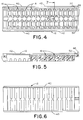
- Figure 4 is a top plan view of a container with its cover removed;
- Figure 5 is an elevational view of the container of Figure 4 (portions have been broken away to more clearly show the internal gasket receiving slot configuration);
- Figure 6 is a bottom plan view of the container shown in Figure 4;
- Figure 7 is a cross-sectional view taking on line 7-7 of Figure 4;
- Figure 8 is a perspective view looking into one of the gasket receiving slots of the container;
- Figure 9 is a top plan view of the gasket container of Figure 4 with the slide cover in position;
- Figure 10 is an end view of the container along line 10-10 of Figure 9;
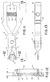
- Figure 11 is a slide elevational view of the gasket inserting tool shown in Figure 1 (the tool is shown gripping a gasket);
- Figure 12 is a view taking on line 12-12 of Figure 11; and
- Figure 13 is a side view taken on line 13-13 of Figure 11.
-
- Referring now to the drawings, Figure 1 is a perspective view illustrating a
gasket storage container 10 comprising a tray-like base member 12 and an associatedslide cover 14. Thegasket container 10 will subsequently be described in great detail but, for the present, it should generally be noted that the gasket container and, in particular, the tray-like base portion 12 includes a plurality of upwardly open, parallel slot andrecess arrangements 16 which are designed to receive and hold individual gasket members in a vertically aligned position for engagement by and removal from the tray through the use of the gripping tool indicated generally with thereference numeral 18. - Before proceeding with a detailed description of the
container 10 and theassociated tool 18, it appears advisable to briefly review the form of gasket for which the assembly is intended to be used. In particular, while the invention could be used with many types of gaskets, either with or without associated retainers, a particularly well suited gasket is of the type generally described and claimed in the said U.S. Patent No. 5 423 580. The disclosure of this patent is herein incorporated by reference. For the present purposes, the gasket is illustrated in perspective in FIGURE 2. In general, the gasket is identified with thenumeral 20 and includes an annular disk-like body 22 having a central throughpassage 24 andopposed seal faces 25a and 25b. The disk-like body 22 has anouter periphery 26 and an associatedretainer element 28 that is connected thereto by an integral web-like joining section 30. Theretainer section 28 is, in this embodiment, resilient and of semi-cylindrical form. It is sized so as to allow it to grip a cylindrical surface on an associated tube coupling component and maintain the annular disk-likeseal gasket portion 22 properly aligned with the coupling faces. This general relationship is shown in FIGURE 3 wherein opposedcoupling components gasket assembly 20 of the type shown in FIGURE 2 preparatory to moving into position between theopposed seal faces 32a and 34a of the coupling components. This type of coupling assembly is generally well known and is shown in prior U.S. Patent Nos. 4,552,389 and 5,145,219. - In the subject gasket embodiment, the
integral retainer portion 28 is arranged to grip about anannular end portion annular gasket body 22 are aligned with the seal faces 32a and 34b, and the associated clamping nuts of the coupling (not shown) can be tightened to cause theseal surfaces 32a and 34a to sealingly engage the gasket faces. - As described in the aforementioned US Patent No. 5,423,580, the advantage of this particular design of gasket and retainer is that gaskets can be installed and replaced between the seal faces of the coupling components without moving the coupling components a significant axial distance apart as was required by prior gasket and retainer combinations.
- With this particular type of gasket and coupling arrangement, it is quite critical that the seal faces 32a and 34a, as well as the opposed sealing faces of the gasket, be treated with care to avoid scratching or even fingerprints under certain conditions.
- As discussed earlier, the subject gasket storage container allows the gaskets to be maintained in a position for ready access by the installer through the use of a tool which is capable of extracting the gaskets from the container and installing them without the necessity of touching the gasket seal faces with either the tool or the operator's hands. Referring in particular to FIGURES 1, 4, 5, and 6, the arrangement of the
gasket container 10 can best be understood. As illustrated, the tray-like base portion 12 of thecontainer 10 comprises the previously-mentioned array of alignedparallel slot assemblies 16 which are arranged in two aligned rows to store thegaskets 20 in side-by-side parallel relationship. The tray-like base member 12 is preferably formed as an injection molded plastic component with theslot assemblies 16 molded to extend downwardly therein from thetop 39. Eachlateral side 40 of the tray-like base member 12 is provided with an outwardly extendingflange portion 42 that is tapered on its top surface as best seen in FIGURE 10. - An
elongated slide cover 14 shown in FIGURE 1 is also preferably molded of plastic and is provided with downwardly extendinglateral sides 43 terminating in an inwardly extendingflange portion 44 that is sized to engage under theflange 42 on the tray-like base member 12. The left end of the cover also includes a downwardly extendingend wall 45. - As can be seen in FIGURE 10,
flange 42 includes inclined upper lateral surfaces 42a. Corresponding, inclined mating surfaces 43a are carried onlateral sides 43. The size relationship betweenlateral sides 43 andflanges 42 is such that the cover is entirely supported by the inclined surfaces 42a and 43a and no contact takes place between the flat underside of the cover14 and the top surface of thebase member 12. Any particles produced by wear between the lid and the base member are formed on the inclined surfaces where there is significantly less likelihood of their being deposited into the container to contaminate the gaskets. - FIGURE 9 shows the
cover 14 in its closed position over thebase 12. In this position, there is an upwardly extendingstop member 46 formed at the end of thebase 12 that is engaged in arecess 48 formed in the right-hand end (as viewed in FIGURE 9) of thecover 14. A downwardly extendinglatch bead 50 is formed on the underside of thecover 14 at the location seen in FIGURE 9. This bead is arranged to enter into a recess 52 (see FIGURES 4 and 5) and resiliently engage therein to retain the cover in its closed position until a substantial force is applied to move the cover to the left as viewed in FIGURE 9 to move it to an open position as shown in FIGURE 1. - Of particular importance is the shape and arrangement of the previously-mentioned
slot assemblies 16. These slot assemblies are best seen and understood by reference to FIGURES 7 and 8. As illustrated therein, each of the slot assemblies includes a centralmain slot portion 56 that extends downwardly from the interiortop surface 58. Thecentral slot 56 has a total lateral width W which is significantly greater than the maximum diameter of thegaskets 20. In addition, the width of the slots identified with W1 is also significantly greater than the thickness of theannular gasket portion 22. At the bottom of each of themain slots 56, there is a narrow inwardly extendingportion 60 that preferably enters from both sides of the slot to an opposed spacing that is only slightly greater than the thickness of theannular gasket body 22 to engage on lateral sides thereof and position the gasket in vertical alignment centrally of themain slot 56. The remaining portions of the gaskets are, however, spaced from the sidewalls of themain slot 56. At one side of themain slot 56, there is arecess 62 that extends laterally and is sized so as to receive theretainer portion 28 of thegasket 20. The gasket is shown in phantom in FIGURE 8 so that theannular body 22 of thegasket 20 can be seen relative to its associatedretainer 28. - As thus illustrated in FIGURE 8, the retainer portion is centrally located in the
recess 62 and is closely received therein to maintain the annular gasket and its seal surfaces centered relative to themain slot portions 56 and the end walls of the slot which are spaced a distance W as previously described. The annular portion of the gasket is thus positioned with the edges in vertical alignment and spaced from the sidewalls and end walls of themain slot 56. The gasket is, however, properly stored and positioned in thebase 12 and is located relative to the top 14 such that when the top is in a closed position, the gasket is retained to prevent vertical dislodgement from themain storage slot 56. - The
tool member 18 is best seen in FIGURES 1 and 11 through 13. As previously-mentioned, this gripping type tool member is arranged so that it is movable into theslot 56 for gripping engagement of the periphery of theannular portion 22 of thegasket 20. In particular, it will be noted that the preferred form of tool comprises a plier like assembly including opposedidentical halves 70 and 72 which are pivotally connected by apivot pin 74. Each of themembers 70, 72 include ajaw end portion 76 and an associatedhandle portion 78. The handles are biased apart to cause thejaw portion 76 to be biased toward one another. In this embodiment, the biasing is achieved through the use of acoil spring 82 that is suitably mounted betweenextensions 84 formed on the interior of thehandles 78. The outer or right-hand end of thehandle 78 preferably include inwardly directed stops 86 that are located and arranged to limit the maximum opening of thejaws 76 in a manner subsequently to be described. - Of particular importance to the
tool 18 is the arrangement of thejaws 76 and their design in relationship to thegasket 20 and thecontainer 10. In the preferred form, thejaws 76 have a thickness T which is only slightly less than the spacing W1 of the main slot opening 56 as illustrated in FIGURE 8. Thus, the jaws can enter and be guided by thesidewalls 56 of the slot. In addition, the jaws include an inner gripping surface or face 88 that has a generally V-shaped configuration as best seen in FIGURE 12. Also, the jaws are contoured in their side view as seen in FIGURE 11 to generally conform to the spherical outer surface of theannular portion 22 ofgasket 20. The V-shaped contour illustrated in FIGURE 12 terminates in atransverse bottom wall 90 that is sized so as to allow the peripheral edge of theannular portion 22 ofgasket 20 to seat therein. The width or thickness t of thejaws 76 is such that when they are engaged with theperiphery 26 of theannular gasket portion 22, they enter between the side of theretainer 28 and thegasket portion 22 as seen in FIGURE 12. The maximum open width of the jaws as defined or limited by the previously-mentionedportions 86 is such that it cannot grip over the retainer portion of the gasket. Also, this maximum width is slightly less than the maximum dimension W of eachslot 56 as illustrated in FIGURE 8. Thus, the tool when gripped by the user and moved to its maximum open position is, in effect, guided by the side and end walls of eachslot 56 to position it ideally relative to thegasket portion 22. A slight release to allow the handles and the jaws to move toward the closed position thus engages and grips the gasket in the jaws and the gasket can be removed from thetray portion 12 of thecontainer 10. It is also located relative to the jaws in a position for installation directly into its sealing relationship with the coupling components as illustrated in FIGURE 3. The arrangement provides that the gasket can be removed and installed into the coupling with a reduced chance of being engaged improperly and with a reduced chance of scratching or damaging the seal faces of the gasket. - The invention has been described with reference to the preferred embodiment. Obviously, modifications and alterations will occur to others upon a reading and understanding of this specification. It is intended to include all such modifications and alterations insofar as they come within the scope of the invention as defined in the claims.
Claims (11)
- A container (10) for holding annular disk-like gaskets (20), the container comprising:a tray-like body (12) having a plurality of slots (16) extending downwardly into the body from the top surface (58) thereof, the slots (16) each having laterally spaced lateral surfaces and longitudinally spaced side surfaces and an open outer end characterized by projecting portions (60) extending inwardly from the side surfaces to form an inner groove within and narrower in longitudinal direction than a respective distance between the side surfaces of the slot, each of said grooves being engageable with a peripheral edge of a respective gasket (20) to support the gasket.
- A container according to Claim 1, comprising a cover (14) slidably mounted to the top of the tray-like body (12).
- A container according to Claim 1 or Claim 2, comprising a laterally extending recess (62) adjacent each slot (16) at the open outer end, the recesses (62) being provided above the narrow inner grooves.
- A container according to any of Claims 1 to 3, wherein the guide surfaces (56) extend parallel to the narrow inner grooves.
- A container according to any of Claims 1 to 4, wherein the tray-like body (12) is moulded from plastics material.
- A gripping tool (18) in combination with a container according to any preceding claim, the gripping tool being operable to remove an annular disk-like gasket (20) from the container (10), the gripping tool (18) comprising:a pair of opposed jaws (76) selectively manually moveable towards and away from one another, the jaws (76) having contoured portions (88) for gripping the peripheral faces (25a, 25b) of the gasket (20).
- A gripping tool according to Claim 6, wherein the jaws (76) have a thickness less than the spacing of the guide surfaces (56), such that in use the guide surfaces (56) engage the gripping tool jaws (76) and guide the contoured portions (88) of the gripping tool (18) into engagement with the peripheral edge of the gasket.
- A gripping tool according to Claim 6 or Claim 7, wherein the contoured portions (88) each comprise a V-shaped groove.
- A plurality of annular disk-like gaskets (20) in combination with a container according to any of Claims 1 to 5, each of said gaskets being supported by a respective inner groove of the container (10), the gaskets (20) each having opposed seal faces (25a, 25b) joined by a peripheral edge (26) that is partly received within respective inner grooves such that diametrically opposed portions of the peripheral edge (26) are exposed from each of the grooves.
- A plurality of annular disk-like gaskets according to Claim 9, wherein each gasket has a C-shaped retainer joined thereto, respective C-shaped retainers facing toward the open end of respective slots.
- In combination:a plurality of disk-like annular gaskets (20), each having opposed seal faces (25a, 25b) joined by a peripheral edge (26);a container (10) having a plurality of slots (16) formed therein, said slots (16) each having laterally spaced lateral surfaces and longitudinally spaced side surfaces, an open outer end and projecting portions (60) extending inwardly from the side surfaces to form an inner groove within and narrower in longitudinal direction than the distance between the side surfaces of the slot (16); the grooves being only slightly wider than the peripheral edge (26) of the gaskets (20) to support the gaskets (20) between said portions (60) in a position where diametrically opposed portions of the gasket peripheral edge are exposed; anda manually operable gripping tool (18) having opposed jaws (76) selectively moveable toward and away from one another, said jaws (76) having contoured portions (88) for gripping engagement with the exposed diametrically opposed peripheral edge portions of the gaskets (20) without engaging the seal faces (25a, 25b), said guide surfaces (56) acting to guide the contoured portions (88) of the gripping tool (18) into engagement with the exposed portions of the peripheral edges (26).
Applications Claiming Priority (2)
| Application Number | Priority Date | Filing Date | Title |
|---|---|---|---|
| US08/306,270 US5445263A (en) | 1994-09-14 | 1994-09-14 | Gasket container and assembly tool |
| US306270 | 1999-05-06 |
Publications (2)
| Publication Number | Publication Date |
|---|---|
| EP0701945A1 EP0701945A1 (en) | 1996-03-20 |
| EP0701945B1 true EP0701945B1 (en) | 1999-04-14 |
Family
ID=23184554
Family Applications (1)
| Application Number | Title | Priority Date | Filing Date |
|---|---|---|---|
| EP95306285A Expired - Lifetime EP0701945B1 (en) | 1994-09-14 | 1995-09-08 | Gasket container and assembly tool |
Country Status (6)
| Country | Link |
|---|---|
| US (1) | US5445263A (en) |
| EP (1) | EP0701945B1 (en) |
| JP (1) | JPH0885586A (en) |
| KR (1) | KR0163633B1 (en) |
| CA (1) | CA2156762A1 (en) |
| DE (1) | DE69509025D1 (en) |
Families Citing this family (12)
| Publication number | Priority date | Publication date | Assignee | Title |
|---|---|---|---|---|
| US5863202A (en) * | 1992-11-24 | 1999-01-26 | Fontenot; Mark G. | Device and method for treatment of dentition |
| US6089370A (en) * | 1999-02-22 | 2000-07-18 | Peak Industries, Inc. | Method and system for packing items |
| ATE541383T1 (en) * | 2005-11-04 | 2012-01-15 | Research In Motion Ltd | CORRECTION OF ERRORS IN RADIO COMMUNICATIONS DEPENDENT ON THE ERROR FREQUENCY |
| US8213317B2 (en) | 2005-11-04 | 2012-07-03 | Research In Motion Limited | Procedure for correcting errors in radio communication, responsive to error frequency |
| ATE494106T1 (en) * | 2006-06-08 | 2011-01-15 | Research In Motion Ltd | Clamping force generation through the use of magnets |
| US7648130B2 (en) | 2006-06-08 | 2010-01-19 | Research In Motion Limited | Use of magnets to provide resilience |
| JP4746487B2 (en) * | 2006-06-22 | 2011-08-10 | シーケーディ株式会社 | Removal tool |
| USD558548S1 (en) * | 2006-06-26 | 2008-01-01 | Hsueh Chin Chang | Pipe disassembling tool |
| JP4999808B2 (en) * | 2008-09-29 | 2012-08-15 | 東京エレクトロン株式会社 | Substrate processing equipment |
| CN112873102B (en) * | 2020-12-29 | 2022-03-11 | 中国原子能科学研究院 | A kind of installation tool of sealing gasket and installation method thereof |
| US12661202B2 (en) * | 2023-08-03 | 2026-06-23 | Plume Design, Inc. | Packaging for a blood glucose monitor |
| US12275578B1 (en) * | 2023-12-21 | 2025-04-15 | Solon Manufacturing Company | Product packaging for washers and method of use |
Family Cites Families (20)
| Publication number | Priority date | Publication date | Assignee | Title |
|---|---|---|---|---|
| US1420729A (en) * | 1922-06-27 | Necticut | ||
| US676490A (en) * | 1900-10-11 | 1901-06-18 | Jacob C De Puy | Pincers. |
| US1057763A (en) * | 1911-10-30 | 1913-04-01 | Mueller Mfg Co H | Method of coupling telescopic pipes. |
| US3191791A (en) * | 1961-05-22 | 1965-06-29 | Expandolite Inc | Container |
| US3773169A (en) * | 1970-12-21 | 1973-11-20 | Crawford Fitting Co | Apparatus for use in the make-up of tube fittings |
| US4172523A (en) * | 1972-03-09 | 1979-10-30 | Walter Becker | Applicator for retaining rings |
| US3759377A (en) * | 1972-03-22 | 1973-09-18 | Paramount Ind Inc | Storage device for rubber o-rings |
| US3923156A (en) * | 1974-04-29 | 1975-12-02 | Fluoroware Inc | Wafer basket |
| US4091919A (en) * | 1976-09-07 | 1978-05-30 | Monsanto | Wafer packaging system |
| CA1223568A (en) * | 1983-04-05 | 1987-06-30 | Professional Packaging Limited | Hinged coin holder |
| US4495689A (en) * | 1983-08-24 | 1985-01-29 | Mcneal Lawrence N | Tool for placement of O-rings and method |
| EP0191881A1 (en) * | 1985-02-21 | 1986-08-27 | Citizen Europe Uhrenhandelsgesellschaft mbh | Display panel |
| US4796756A (en) * | 1988-04-11 | 1989-01-10 | Silor Optical Of Florida, Inc. | Optical lens carrier |
| US5145219A (en) * | 1990-08-01 | 1992-09-08 | Cajon Company | Tube coupling with gasket retainer |
| US5062191A (en) * | 1990-10-09 | 1991-11-05 | Carr Luther J | Locking ring tool |
| US5046611A (en) * | 1990-10-22 | 1991-09-10 | Edward Weck Incorporated | Hemostatic clip cartridge |
| US5114014A (en) * | 1991-02-19 | 1992-05-19 | David Ascalon | Token holder |
| US5226230A (en) * | 1991-12-13 | 1993-07-13 | Itt Corporation | Universal o.d. release tool |
| US5279416A (en) * | 1992-06-05 | 1994-01-18 | Edward Weck Incorporated | Ligating device cartridge with separable retainer |
| US5423580A (en) * | 1994-01-26 | 1995-06-13 | Cajon Company | Fluid coupling with gasket retainer |
-
1994
- 1994-09-14 US US08/306,270 patent/US5445263A/en not_active Expired - Fee Related
-
1995
- 1995-08-23 CA CA002156762A patent/CA2156762A1/en not_active Abandoned
- 1995-09-08 EP EP95306285A patent/EP0701945B1/en not_active Expired - Lifetime
- 1995-09-08 DE DE69509025T patent/DE69509025D1/en not_active Expired - Lifetime
- 1995-09-12 JP JP7233829A patent/JPH0885586A/en active Pending
- 1995-09-12 KR KR1019950029623A patent/KR0163633B1/en not_active Expired - Fee Related
Also Published As
| Publication number | Publication date |
|---|---|
| EP0701945A1 (en) | 1996-03-20 |
| KR960011239A (en) | 1996-04-20 |
| KR0163633B1 (en) | 1998-12-01 |
| CA2156762A1 (en) | 1996-03-15 |
| JPH0885586A (en) | 1996-04-02 |
| US5445263A (en) | 1995-08-29 |
| DE69509025D1 (en) | 1999-05-20 |
Similar Documents
| Publication | Publication Date | Title |
|---|---|---|
| US5445263A (en) | Gasket container and assembly tool | |
| US9079757B2 (en) | Cap handling tool and method of use | |
| US5518278A (en) | Coupling | |
| US5584513A (en) | Push in plastic tube fitting | |
| US5143359A (en) | Swivel clamp guard | |
| US20210230850A1 (en) | Apparatus and method for valve cartridge extraction | |
| US4714138A (en) | Engine sump draining device | |
| US20040103511A1 (en) | Seal Puller | |
| US5425400A (en) | Transfer port apparatus and method | |
| CN104540643A (en) | Hand tool for use in the quick disconnection of quick connect/disconnect couplings | |
| US5765890A (en) | Device for transferring a semiconductor wafer | |
| JPH09504350A (en) | Mounting pin for quick connector | |
| US20080238088A1 (en) | Method for assembling and disassembling a pipe fitting arrangement with a tool and such a tool | |
| US20120073763A1 (en) | Device for maintaining sterile integrity of connected fluid pathways | |
| US5564175A (en) | O-ring remover tool | |
| US5862578A (en) | Insertion tool | |
| WO1989000973A1 (en) | A device for use in connection with tapping off fluid from or filling fluid into a container | |
| US4222985A (en) | Laboratory tool | |
| US12472643B2 (en) | Plate handling devices and methods for plate handling of analytical and culture vessels | |
| US4295260A (en) | Tool for removing sleeves from cylinders | |
| US3389654A (en) | Article-lifting and stamping apparatus | |
| US5601940A (en) | Battery holder | |
| US2602628A (en) | Fluid transfer system and apparatus | |
| JP2002513900A (en) | Control valve main seal retainer with assembly and removal tools | |
| US4375173A (en) | Saw chain holding device |
Legal Events
| Date | Code | Title | Description |
|---|---|---|---|
| PUAI | Public reference made under article 153(3) epc to a published international application that has entered the european phase |
Free format text: ORIGINAL CODE: 0009012 |
|
| AK | Designated contracting states |
Kind code of ref document: A1 Designated state(s): BE DE FR GB |
|
| 17P | Request for examination filed |
Effective date: 19960819 |
|
| 17Q | First examination report despatched |
Effective date: 19970430 |
|
| GRAG | Despatch of communication of intention to grant |
Free format text: ORIGINAL CODE: EPIDOS AGRA |
|
| GRAG | Despatch of communication of intention to grant |
Free format text: ORIGINAL CODE: EPIDOS AGRA |
|
| GRAH | Despatch of communication of intention to grant a patent |
Free format text: ORIGINAL CODE: EPIDOS IGRA |
|
| GRAH | Despatch of communication of intention to grant a patent |
Free format text: ORIGINAL CODE: EPIDOS IGRA |
|
| GRAA | (expected) grant |
Free format text: ORIGINAL CODE: 0009210 |
|
| AK | Designated contracting states |
Kind code of ref document: B1 Designated state(s): BE DE FR GB |
|
| PG25 | Lapsed in a contracting state [announced via postgrant information from national office to epo] |
Ref country code: FR Free format text: LAPSE BECAUSE OF FAILURE TO SUBMIT A TRANSLATION OF THE DESCRIPTION OR TO PAY THE FEE WITHIN THE PRESCRIBED TIME-LIMIT Effective date: 19990414 Ref country code: BE Free format text: LAPSE BECAUSE OF FAILURE TO SUBMIT A TRANSLATION OF THE DESCRIPTION OR TO PAY THE FEE WITHIN THE PRESCRIBED TIME-LIMIT Effective date: 19990414 |
|
| REF | Corresponds to: |
Ref document number: 69509025 Country of ref document: DE Date of ref document: 19990520 |
|
| PG25 | Lapsed in a contracting state [announced via postgrant information from national office to epo] |
Ref country code: DE Free format text: LAPSE BECAUSE OF FAILURE TO SUBMIT A TRANSLATION OF THE DESCRIPTION OR TO PAY THE FEE WITHIN THE PRESCRIBED TIME-LIMIT Effective date: 19990715 |
|
| PG25 | Lapsed in a contracting state [announced via postgrant information from national office to epo] |
Ref country code: GB Free format text: LAPSE BECAUSE OF NON-PAYMENT OF DUE FEES Effective date: 19990908 |
|
| EN | Fr: translation not filed | ||
| PLBE | No opposition filed within time limit |
Free format text: ORIGINAL CODE: 0009261 |
|
| STAA | Information on the status of an ep patent application or granted ep patent |
Free format text: STATUS: NO OPPOSITION FILED WITHIN TIME LIMIT |
|
| 26N | No opposition filed | ||
| GBPC | Gb: european patent ceased through non-payment of renewal fee |
Effective date: 19990908 |