EP0701663B1 - Air bearing control system - Google Patents
Air bearing control system Download PDFInfo
- Publication number
- EP0701663B1 EP0701663B1 EP94905348A EP94905348A EP0701663B1 EP 0701663 B1 EP0701663 B1 EP 0701663B1 EP 94905348 A EP94905348 A EP 94905348A EP 94905348 A EP94905348 A EP 94905348A EP 0701663 B1 EP0701663 B1 EP 0701663B1
- Authority
- EP
- European Patent Office
- Prior art keywords
- air
- machine
- valve
- controller
- set forth
- Prior art date
- Legal status (The legal status is an assumption and is not a legal conclusion. Google has not performed a legal analysis and makes no representation as to the accuracy of the status listed.)
- Expired - Lifetime
Links
Images

Classifications
-
- F—MECHANICAL ENGINEERING; LIGHTING; HEATING; WEAPONS; BLASTING
- F16—ENGINEERING ELEMENTS AND UNITS; GENERAL MEASURES FOR PRODUCING AND MAINTAINING EFFECTIVE FUNCTIONING OF MACHINES OR INSTALLATIONS; THERMAL INSULATION IN GENERAL
- F16C—SHAFTS; FLEXIBLE SHAFTS; ELEMENTS OR CRANKSHAFT MECHANISMS; ROTARY BODIES OTHER THAN GEARING ELEMENTS; BEARINGS
- F16C32/00—Bearings not otherwise provided for
- F16C32/06—Bearings not otherwise provided for with moving member supported by a fluid cushion formed, at least to a large extent, otherwise than by movement of the shaft, e.g. hydrostatic air-cushion bearings
- F16C32/0629—Bearings not otherwise provided for with moving member supported by a fluid cushion formed, at least to a large extent, otherwise than by movement of the shaft, e.g. hydrostatic air-cushion bearings supported by a liquid cushion, e.g. oil cushion
- F16C32/064—Bearings not otherwise provided for with moving member supported by a fluid cushion formed, at least to a large extent, otherwise than by movement of the shaft, e.g. hydrostatic air-cushion bearings supported by a liquid cushion, e.g. oil cushion the liquid being supplied under pressure
- F16C32/0644—Details of devices to control the supply of liquids to the bearings
-
- B—PERFORMING OPERATIONS; TRANSPORTING
- B23—MACHINE TOOLS; METAL-WORKING NOT OTHERWISE PROVIDED FOR
- B23Q—DETAILS, COMPONENTS, OR ACCESSORIES FOR MACHINE TOOLS, e.g. ARRANGEMENTS FOR COPYING OR CONTROLLING; MACHINE TOOLS IN GENERAL CHARACTERISED BY THE CONSTRUCTION OF PARTICULAR DETAILS OR COMPONENTS; COMBINATIONS OR ASSOCIATIONS OF METAL-WORKING MACHINES, NOT DIRECTED TO A PARTICULAR RESULT
- B23Q1/00—Members which are comprised in the general build-up of a form of machine, particularly relatively large fixed members
- B23Q1/25—Movable or adjustable work or tool supports
- B23Q1/26—Movable or adjustable work or tool supports characterised by constructional features relating to the co-operation of relatively movable members; Means for preventing relative movement of such members
- B23Q1/38—Movable or adjustable work or tool supports characterised by constructional features relating to the co-operation of relatively movable members; Means for preventing relative movement of such members using fluid bearings or fluid cushion supports
-
- F—MECHANICAL ENGINEERING; LIGHTING; HEATING; WEAPONS; BLASTING
- F16—ENGINEERING ELEMENTS AND UNITS; GENERAL MEASURES FOR PRODUCING AND MAINTAINING EFFECTIVE FUNCTIONING OF MACHINES OR INSTALLATIONS; THERMAL INSULATION IN GENERAL
- F16C—SHAFTS; FLEXIBLE SHAFTS; ELEMENTS OR CRANKSHAFT MECHANISMS; ROTARY BODIES OTHER THAN GEARING ELEMENTS; BEARINGS
- F16C32/00—Bearings not otherwise provided for
- F16C32/06—Bearings not otherwise provided for with moving member supported by a fluid cushion formed, at least to a large extent, otherwise than by movement of the shaft, e.g. hydrostatic air-cushion bearings
-
- F—MECHANICAL ENGINEERING; LIGHTING; HEATING; WEAPONS; BLASTING
- F16—ENGINEERING ELEMENTS AND UNITS; GENERAL MEASURES FOR PRODUCING AND MAINTAINING EFFECTIVE FUNCTIONING OF MACHINES OR INSTALLATIONS; THERMAL INSULATION IN GENERAL
- F16C—SHAFTS; FLEXIBLE SHAFTS; ELEMENTS OR CRANKSHAFT MECHANISMS; ROTARY BODIES OTHER THAN GEARING ELEMENTS; BEARINGS
- F16C2322/00—Apparatus used in shaping articles
- F16C2322/39—General buildup of machine tools, e.g. spindles, slides, actuators
-
- Y—GENERAL TAGGING OF NEW TECHNOLOGICAL DEVELOPMENTS; GENERAL TAGGING OF CROSS-SECTIONAL TECHNOLOGIES SPANNING OVER SEVERAL SECTIONS OF THE IPC; TECHNICAL SUBJECTS COVERED BY FORMER USPC CROSS-REFERENCE ART COLLECTIONS [XRACs] AND DIGESTS
- Y10—TECHNICAL SUBJECTS COVERED BY FORMER USPC
- Y10S—TECHNICAL SUBJECTS COVERED BY FORMER USPC CROSS-REFERENCE ART COLLECTIONS [XRACs] AND DIGESTS
- Y10S33/00—Geometrical instruments
- Y10S33/02—Air
Definitions
- the invention relates to air bearings. More particularly, the invention relates to a system for reducing air consumption of an air bearing during periods of non-use.
- a bearing generally refers to the area where a first part of a machine supports another part which can move relative to the first part.
- An air bearing is a particular type of bearing in which a stream of pressurized air is forced through a gap between the two parts to maintain relatively frictionless support.
- Air bearings are commonly used in coordinate measuring machines in order to provide essentially frictionless movement between parts, thus allowing high speed movement and accurate placement. Air bearings, however, require a large amount of pressurized air per unit time and thus have relatively high operating costs.
- an air compressor is run to supply a holding tank with enough air to keep the pressure in the tank between specified minimum and maximum levels. Air is released to the air bearing through a valve, a pressure regulator, and an outlet which leads from the tank to the bearing.
- the compressor is electrically feedback controlled to maintain the pressure in the olding tank within the specified pressure range, e.g., 9,8-11,8 bar (10-12 atmospheres).
- the invention comprises a digital controller coupled to an outlet valve which controls air flow between an air storage tank and the air bearings for opening and closing the valve responsive to certain inputs.
- the controller is coupled to receive inputs from the main machine controller. If the machine is in the full operation mode, but is inactive for a specified period of time, e.g., three minutes, the valve controller causes the machine to enter a standby mode by shutting the valve, thus turning the air bearing off, and halting depletion of the air from the air storage tank. Accordingly, the air compressor can then turn off during machine idle periods because air in the tank will not be depleted through the air bearing.
- the main controller of the machine is coupled to receive a signal from the air bearing controller which indicates whether the air bearing is on or off.
- the main controller is programmed so as not to accept control inputs until the air bearing is on.
- the air bearing is turned on by operation of an input device such as a push button, a mouse, a light pen or touch screen.
- the valve controller and the main controller open the tank outlet valve and return the machine to full operation mode, respectively.
- FIG. 1 is a plan view of an exemplary three-axis bridge type coordinate measuring machine having air bearings.
- An object to be measured is placed on table 14 and is contacted by probe 12 which is mounted on z-rail 18.
- Z-rail 18 can move vertically within an air bearing (not shown) in air bearing carriage 24, thus providing a vertical motion component to probe 12 (z-axis component).
- Air bearing carriage 24 is further mounted on beam 20 by a second air bearing (not shown).
- Carriage 24 is movable in the horizontal direction (the x direction) along x-rail 20 thus providing a second degree of mobility of probe 12.
- x-raii 20 is part of a bridge structure 16 which is coupled to table 11 by a further series of air bearings illustrated at 26 in FIG. 1.
- Bridge 16 is driven by y-axis drive motor 29 in the direction perpendicular to the page (the y direction). Air bearings 26 maintain the position of bridge 16 to table 11 in the x and z directions. In this structure, probe 12 can be moved three dimensionally.
- the actual drive mechanisms for moving the various components such as (1) z-rail 18 relative to carriage 24 or (2) carriage 24 relative to x-rail 20 or (3) bridge relative to table 11 may be of a variety of types such as hydraulic, rack and pinion, or gear driven. The actual driving mechanism, is conventional and will not be discussed further herein.
- FIG. 2 is a cross-sectional view of an exemplary prior art air bearing in greater detail.
- FIG. 2 may be one of the air bearings coupling carriage 24 to x-rail 20 and will be described as such.
- Bearing shoe 28 is fixedly mounted to carriage 24 and is positioned adjacent to x-rail 20.
- Air compressor 31 supplies air to air tank 32 through outlet 33 and valve 35.
- Air tank 32 is coupled to main channel 30 in shoe 28 through flexible hose 37, pressure regulator 41 and orifice 34.
- air compressor 31 is feedback controlled to maintain a specified pressure in air tank 32, e.g., 9,8-11,8 bar (10-12 atmospheres).
- orifice 34 When the machine is in full operation mode, orifice 34 is open such that pressurized air escapes through hose 37 into main channel 30 of air bearing shoe 28.
- Main channel 30 in this instance is an annular reservoir which is fluidly coupled to gap 43 via channels 36.
- the pressurized air in main channel 30 flows into gap 43 via channels 36, and escapes from gap 43 as shown by the arrows labeled "out" in FIG. 2.
- This flow of pressurized air maintains the gap between surface 39 of shoe 28 and surface 75 of x-rail 20 thus providing essentially frictionless support between carriage 24 and x-rail 20.
- Carriage 24 (which is fixedly coupled to bearing shoe 28) can then be slid in a horizontal direction (the x direction) relative to x-rail 20 by a drive mechanism (not shown).
- the air bearings maintain relatively frictionless support between the parts and the relative orientation of the parts in the y and z directions.
- the primary purposes of the air bearing are (1) to maintain accurate positioning of carriage 24 with respect to x-rail 20 in directions orthogonal to the direction in which carriage 24 moves along x-rail 20, and 2) to maintain essentially frictionless support between the two members so as to minimize wear and maximize the speed with which relative movement can be made.
- the primary purposes of the air bearing are (1) to maintain accurate positioning of carriage 24 with respect to x-rail 20 in directions orthogonal to the direction in which carriage 24 moves along x-rail 20, and 2) to maintain essentially frictionless support between the two members so as to minimize wear and maximize the speed with which relative movement can be made.
- the present invention provides an air bearing system in which the air supply to the bearing gap is interrupted during extended periods of machine inactivity (i.e., the probe is not moving or making a measurement).
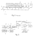
- FIG. 3 is a schematic of the air bearing system of the present invention which can be used with any type of machine including that shown in FIGS. 1 and 2.
- An air compressor 50 supplies pressurized air to air supply tank 52 via hose 51 and valve 53.
- the pressure sensor 54 senses the pressure in the supply tank 52 and provides a signal via line 55 to compressor controller 56 indicating the instantaneous pressure in supply tank 52.
- Compressor controller 56 is programmed to turn on air compressor 50 when the pressure in tank 52 drops below a certain specified pressure, e.g., 9,8 bar (10 atmospheres), and to turn off air compressor 50 when the pressure in air supply tank 52 rises above a second specified pressure, e.g., 11,8 bar (12 atmospheres). In this manner, the pressure in air supply tank 52 is maintained between the two pressures.
- Air supply tank 52 is vented through regulator 57 and valve 58 into air bearing 60.
- valve 58 Operation of valve 58 is controlled by a control circuit 62.
- Valve 58 can be placed by control circuit 62 into one of two positions, open or closed. In the open position, valve 58 couples air supply tank 52 to air bearing 60 in accordance with normal operation of the bearing. In the closed position, the outlet of air supply tank 52 is sealed and air bearing 60 is coupled to vent 64 which allows the air pressure in the bearing 60 to be released more quickly than only through the gap 61.
- Controller 62 of valve 58 is coupled to receive a signal 59 from the main machine controller 66.
- the main controller 66 is designed to assert signal line 59 every time the probe is moved or a measurement is obtained.
- Controller 62 is programmed to switch valve 58 from the open position to the closed position if signal line 59 from the main machine controller 66 is not asserted for a certain period since the last input. Thus, if the machine remains idle for longer than the specified time period, valve 58 is switched to the closed position (i.e., air bearing 60 is turned off).
- the valve controller 62 is further programmed to provide a signal on line 67 to the main machine controller 66, which signal is asserted when the air bearing has been turned off.
- the main machine controller 66 is programmed to inhibit movement of probe 12 and measurement when the signal on line 67 is asserted.
- the machine further comprises an operator input device 68 such as a push button, mouse, light pen or touch screen through which an operator can input an instruction indicating that the air bearing 60 is to be turned on. Alternately, or in addition, the operation of any button on the machine can be used as a signal indicating that the bearing is to be activated.
- the input device 68 is coupled to the valve controller 62 via signal line 69.
- line 69 is asserted and controller 62, responsive to the assertion of line 69, switches valve 58 from the closed to the open position via control line 71.
- signal line 67 to main machine controller 66 is brought to the unasserted state. In the preferred embodiment, there is a time delay before line 67 is unasserted in order to provide a period for the air pressure in the air bearing to build up to full pressure.
- control line 59 from the main machine controller 66 to the valve controller 62 might, alternately, be asserted by main machine controller 66 after a specified time period of inactivity, in which case valve controller 62 would be programmed to switch valve 58 to the closed position whenever line 59 is asserted, as opposed to when it is unasserted for a specified time interval.
- the function of controller 62 may simply be incorporated within the programming of main machine controller 66 and therefore eliminate the need for a separate valve controller.
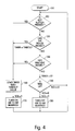
- FIG. 4 is a flowchart illustrating the operation of the valve controller in one preferred embodiment of the present invention.
- the operator can turn the air bearing on by use of either a button on a keyboard or a mouse.
- the valve controller includes or has access to a clock which continuously counts down at a specified rate. Therefore, the operation of the clock is not shown in the flow chart.
- step 110 the valve controller determines if any button on the keyboard has been pressed by the operator to turn the air bearing on. If it has not, procedure flows to-step 120 where the controller determines if the mouse has been operated indicating that the air bearing is to be turned on. If not, procedure flows to step 130 where the controller determines if the probe has been moved or a measurement has been taken since the last passage through the procedure loop. If it has not, the controller checks the clock to determine if the specified period of time of inactivity has elapsed. If it has not, programming loops back around to step 110. However, if the timer has run out, procedure flows to step 150 where the air bearing is turned off and then procedure loops back around to step 110.
- step 170 the procedure loops back around to step 110.
Landscapes
- Engineering & Computer Science (AREA)
- General Engineering & Computer Science (AREA)
- Mechanical Engineering (AREA)
- Magnetic Bearings And Hydrostatic Bearings (AREA)
- Organic Low-Molecular-Weight Compounds And Preparation Thereof (AREA)
- Transition And Organic Metals Composition Catalysts For Addition Polymerization (AREA)
- Rolling Contact Bearings (AREA)
Abstract
Description
Claims (21)
- Apparatus for controlling air flow to an air bearing (60) for providing support between first and second parts of a machine which are movable relative to each other, said apparatus comprising:an air supply (50, 52),means (57, 58) coupling air from said air supply to the air bearing, anda valve (58) within said coupling means, said valve being selectively positionable in a first position in which air from said air supply is coupled to the air bearing and in a second position in which said coupling means is closed in which air from said air supply is not coupled to the air bearing, characterised in that there is provideda valve controller (62) for switching said valve from the open position to the closed position when the machine has been inactive for a specified time interval.
- Apparatus as set forth in claim 1, wherein said valve controller (62) comprises a microprocessor.
- Apparatus as set forth in claim 1, wherein the air supply comprises an air tank (52) and when said valve (58) is closed, said air tank is sealed such that air does not escape from said air tank.
- Apparatus as set forth in claim 3, wherein said machine further comprises a main machine controller (66) and wherein said main machine controller (66) and said valve controller (62) are integrated in a single microprocessor.
- Apparatus as set forth in claim 3, wherein said machine further comprises a main machine controller (66) and wherein said valve controller (62) is responsive to a signal from said main machine controller (66) indicative of the time elapsed since the last machine activity.
- Apparatus as set forth in claim 5, wherein said machine is a coordinate measuring machine and said machine is inactive when there is no relative movement between said first and second parts of said machine.
- Apparatus as set forth in claim 1, wherein, when said valve (58) is in said closed position, said valve couples said air bearing (60) to a release port (64) whereby air can escape from said air bearing through said release port.
- Apparatus as set forth in claim 6, wherein said coordinate measuring machine comprises a main machine controller (66) for controlling operation of said machine including control of relative movement of said first and second parts and measuring, and wherein said main machine controller (66) is coupled to said valve controller (62) so as to provide an operation signal to said valve controller (62) which signal is asserted each time the machine is active and further wherein said valve controller (62) comprises a timing circuit for tracking the time interval since said operation signal has been asserted.
- Apparatus as set forth in claim 8, wherein said main machine controller (66) and said valve controller (62) are integrally formed in a microprocessor.
- Apparatus as set forth in claim 1, further comprising an input device (68) through which an operator can input a signal instructing said valve controller (62) to switch from the closed position to the open position.
- Apparatus for controlling air flow to an air bearing (60) which provides support between first and second parts of a coordinate measuring machine, which parts are movable relative to each other, said apparatus comprising;an air tank (52) for holding air under pressure,a pressure sensor (54) coupled to said air tank for sensing the air pressure in said tank,an air compressor (50) coupled to said air tank (52) and said pressure sensor (54) for supplying air to said tank,the air bearing (60),an air path coupling air from said air tank (52) to said air bearing(60),a valve (58) within said air path, said valve (58) being selectively positionable in an open position in which air from said air tank (52) is coupled to said air bearing (60) and in a closed position in which said air path is closed such that air cannot escape from said air tank (52), characterised in that there is provideda valve controller (62), for switching said valve (58) from the open position to the closed position when said machine has been inactive for a specified time interval.
- Apparatus as set forth in claim 11, wherein said valve controller (62) comprises a microprocessor.
- Apparatus as set forth in claim 12, wherein said machine further comprises a main machine controller (66) and wherein said valve controller (62) is responsive to a signal from the main machine controller (66) indicative of the time elapsed since said machine has been active.
- Apparatus as set forth in clam 13, wherein, when said valve (58) is in said closed position, said valve couples said air bearing (60) to a release port (64) whereby air can escape from said air bearing through said release port.
- Apparatus as set forth in claim 12, wherein said coordinate measuring machine comprises a main machine controller (66) for controlling operation of said machine including control of relative movement of said first and second parts and measuring, and wherein said main machine controller (66) is coupled to said valve controller (62) so as to provide an operation signal to said valve controller, which signal is asserted each time said machine is active and further wherein said valve controller (62) comprises a timing circuit for tracking the time interval since said operation signal has been asserted.
- Apparatus as set forth in claim 15, further comprising an input device (68) through which an operator can input a signal instructing said valve controller (62) to switch from the closed position to the open position.
- Apparatus as set forth in claim 16, wherein said input device (68) includes all controls for operating said machine.
- A method of controlling a machine having an air bearing (60) for providing support between first and second machine parts which are movable relative to each other, said method comprising the step of:(1) providing air to said air bearing (60) when the machine is fully operating, characterised in that the method further comprises the steps of:(2) determining the time interval since said machine has been active, and(3) interrupting the provision of air to said air bearing (60) when said time interval exceeds a specified period.
- A method as set forth in claim 18, wherein said machine is a coordinate measuring machine and step 2 comprises the steps of:(2.1) determining the time interval since there has been relative movement between said first and second machine parts or since a measurement was obtained, whichever is smaller.
- A method as set forth in claim 19, wherein said air is provided to said air bearing (60) from an air tank (52) containing pressurized air, and wherein said air tank is supplied with air from an air compressor (50) which supplies said air responsive to the pressure in said tank dropping below a specified pressure, said tank (52) being coupled to said air bearing (60) through a valve (58), wherein step 3 comprises the step of:(3.1) closing said valve (58) such that the air cannot escape from said tank.
- A method as set forth in claim 20, wherein said machine further comprises an input device (68) through which an operator can input a signal indicating that said provision of air to said air bearing (60) is to be required, said method further comprising the step of:(4) opening said valve (58) responsive to said signal such that said air in said air tank (52) is coupled to said bearing (60).
Applications Claiming Priority (3)
| Application Number | Priority Date | Filing Date | Title |
|---|---|---|---|
| US988467 | 1992-12-10 | ||
| US07/988,467 US5347723A (en) | 1992-12-10 | 1992-12-10 | Air bearing control system |
| PCT/US1993/011929 WO1994013969A1 (en) | 1992-12-10 | 1993-12-08 | Air bearing control system |
Publications (2)
| Publication Number | Publication Date |
|---|---|
| EP0701663A1 EP0701663A1 (en) | 1996-03-20 |
| EP0701663B1 true EP0701663B1 (en) | 1998-07-29 |
Family
ID=25534145
Family Applications (1)
| Application Number | Title | Priority Date | Filing Date |
|---|---|---|---|
| EP94905348A Expired - Lifetime EP0701663B1 (en) | 1992-12-10 | 1993-12-08 | Air bearing control system |
Country Status (7)
| Country | Link |
|---|---|
| US (1) | US5347723A (en) |
| EP (1) | EP0701663B1 (en) |
| JP (1) | JPH08508326A (en) |
| AT (1) | ATE169094T1 (en) |
| DE (1) | DE69320069T2 (en) |
| ES (1) | ES2119164T3 (en) |
| WO (1) | WO1994013969A1 (en) |
Cited By (3)
| Publication number | Priority date | Publication date | Assignee | Title |
|---|---|---|---|---|
| DE102010006297A1 (en) * | 2010-01-21 | 2011-07-28 | Carl Zeiss Industrielle Messtechnik GmbH, 73447 | Machine and method for operating a machine |
| WO2014161568A1 (en) | 2013-04-02 | 2014-10-09 | Carl Zeiss Industrielle Messtechnik Gmbh | Method for determining a shape contour on an object to be measured |
| DE102011112734B4 (en) | 2010-09-21 | 2022-02-17 | Mitutoyo Corporation | Industrial machine and control method for the same |
Families Citing this family (10)
| Publication number | Priority date | Publication date | Assignee | Title |
|---|---|---|---|---|
| EP0849035A1 (en) * | 1996-12-20 | 1998-06-24 | Pwb Ag Praezisions-Werkzeug-Bau | Pre-adjusting device for machine tools |
| DE19809690A1 (en) * | 1998-03-06 | 1999-09-09 | Zeiss Carl Fa | Coordinate measuring device with user guidance |
| US6246138B1 (en) | 1998-12-24 | 2001-06-12 | Honeywell International Inc. | Microturbine cooling system |
| DE20118421U1 (en) | 2001-11-13 | 2002-02-21 | FESTO AG & Co., 73734 Esslingen | Air bearing monitoring device |
| DE102004020759A1 (en) * | 2004-04-27 | 2005-11-24 | Langer Gmbh | Flexible holding device for temporarily positioning components for coordinate measurement, has holder which moves to set position defined by dimensions of desired assembly |
| US9441935B2 (en) | 2014-07-07 | 2016-09-13 | Tokyo Seimitsu Co., Ltd. | Three-dimensional coordinate measuring machine |
| KR102751282B1 (en) * | 2019-07-12 | 2025-01-10 | 현대자동차주식회사 | Air compressor for fuel cell system |
| CN116057292A (en) * | 2020-07-30 | 2023-05-02 | 发那科株式会社 | Pressurized fluid supply system |
| CN113027922B (en) * | 2021-03-12 | 2021-12-07 | 山东赛马力发电设备有限公司 | High-speed air suspension bearing |
| DE102021113910A1 (en) * | 2021-05-28 | 2022-12-01 | Zf Cv Systems Global Gmbh | Fuel cell system for driving a vehicle |
Family Cites Families (5)
| Publication number | Priority date | Publication date | Assignee | Title |
|---|---|---|---|---|
| US3720288A (en) * | 1971-08-09 | 1973-03-13 | Allis Chalmers | Lubrication system for grinding mill or the like |
| US4535812A (en) * | 1982-07-12 | 1985-08-20 | The Boc Group, Inc. | Time controlled gas flows |
| US4610089A (en) * | 1985-12-05 | 1986-09-09 | The Warner & Swasey Company | Bridge type coordinate measuring machine |
| US4949465A (en) * | 1986-10-31 | 1990-08-21 | Brown & Sharpe Manufacturing Company | Counterweight for coordinate measuring machine |
| DE3723466A1 (en) * | 1987-07-16 | 1989-01-26 | Barry Controls Gmbh | ADJUSTMENT DEVICE FOR CORRECTING THE POSITION OF A MACHINE |
-
1992
- 1992-12-10 US US07/988,467 patent/US5347723A/en not_active Expired - Lifetime
-
1993
- 1993-12-08 EP EP94905348A patent/EP0701663B1/en not_active Expired - Lifetime
- 1993-12-08 AT AT94905348T patent/ATE169094T1/en active
- 1993-12-08 ES ES94905348T patent/ES2119164T3/en not_active Expired - Lifetime
- 1993-12-08 WO PCT/US1993/011929 patent/WO1994013969A1/en not_active Ceased
- 1993-12-08 JP JP6514372A patent/JPH08508326A/en active Pending
- 1993-12-08 DE DE69320069T patent/DE69320069T2/en not_active Expired - Fee Related
Cited By (5)
| Publication number | Priority date | Publication date | Assignee | Title |
|---|---|---|---|---|
| DE102010006297A1 (en) * | 2010-01-21 | 2011-07-28 | Carl Zeiss Industrielle Messtechnik GmbH, 73447 | Machine and method for operating a machine |
| US8590875B2 (en) | 2010-01-21 | 2013-11-26 | Carl Zeiss Industrielle Messtechnik Gmbh | Machine having an air bearing and method for operating such a machine |
| DE102011112734B4 (en) | 2010-09-21 | 2022-02-17 | Mitutoyo Corporation | Industrial machine and control method for the same |
| WO2014161568A1 (en) | 2013-04-02 | 2014-10-09 | Carl Zeiss Industrielle Messtechnik Gmbh | Method for determining a shape contour on an object to be measured |
| US10060737B2 (en) | 2013-04-02 | 2018-08-28 | Carl Zeiss Industrielle Messtechnik Gmbh | Method and machine for determining a shape contour on a measurement object |
Also Published As
| Publication number | Publication date |
|---|---|
| US5347723A (en) | 1994-09-20 |
| WO1994013969A1 (en) | 1994-06-23 |
| ATE169094T1 (en) | 1998-08-15 |
| DE69320069D1 (en) | 1998-09-03 |
| EP0701663A1 (en) | 1996-03-20 |
| DE69320069T2 (en) | 1999-04-08 |
| JPH08508326A (en) | 1996-09-03 |
| ES2119164T3 (en) | 1998-10-01 |
Similar Documents
| Publication | Publication Date | Title |
|---|---|---|
| US5347723A (en) | Air bearing control system | |
| US4698774A (en) | Method of and apparatus for controlling automatic soldering system | |
| US6359251B1 (en) | Centralized control architecture for a plasma arc system | |
| US6900408B2 (en) | Centralized control architecture for a plasma arc system | |
| US5150102A (en) | Machining fluid temperature deviation alarm | |
| US10042347B2 (en) | Standby control for machine tools | |
| CN106970590B (en) | A kind of paper tape correcting controller and method for correcting error | |
| US7210222B2 (en) | Power supply control method | |
| JP5700765B2 (en) | Industrial machinery | |
| US20030103825A1 (en) | Machine tool with thermal deformation suppressing function | |
| US6176179B1 (en) | Screen printer and a screen printing method | |
| EP0806603B1 (en) | Method and apparatus for automatically feeding lubricating oil using microcomputer | |
| US5235532A (en) | Information processing apparatus for performing operations in response to the opening and the closing of a cover thereof | |
| US5461700A (en) | Robot control system with a record switch for recording only useful instruction/positional data of a teaching-playback robot | |
| CN207014204U (en) | Polishing machine | |
| DE3780093D1 (en) | LIQUID DISPENSING DEVICE. | |
| US6000889A (en) | Thermal change computation apparatus for machine tool and storage medium for executing the computation | |
| JP2006156655A (en) | Substrate processing apparatus and liquid feeding system | |
| KR100552411B1 (en) | Electric discharge processing equipment | |
| JP3339807B2 (en) | Machine tool thermal displacement calculator and storage medium | |
| JPS61118519A (en) | Automatic engine oil supply device | |
| KR200242898Y1 (en) | Apparatus for silicone dispense in liquid crystal display | |
| JPH0419038A (en) | Lubricating device | |
| JPH0232070B2 (en) | ||
| JPH1153012A (en) | Machine tool thermal displacement calculator and storage medium |
Legal Events
| Date | Code | Title | Description |
|---|---|---|---|
| PUAI | Public reference made under article 153(3) epc to a published international application that has entered the european phase |
Free format text: ORIGINAL CODE: 0009012 |
|
| 17P | Request for examination filed |
Effective date: 19950626 |
|
| AK | Designated contracting states |
Kind code of ref document: A1 Designated state(s): AT BE CH DE DK ES FR GB GR IE IT LI LU MC NL PT SE |
|
| 17Q | First examination report despatched |
Effective date: 19960515 |
|
| GRAG | Despatch of communication of intention to grant |
Free format text: ORIGINAL CODE: EPIDOS AGRA |
|
| GRAG | Despatch of communication of intention to grant |
Free format text: ORIGINAL CODE: EPIDOS AGRA |
|
| GRAG | Despatch of communication of intention to grant |
Free format text: ORIGINAL CODE: EPIDOS AGRA |
|
| GRAH | Despatch of communication of intention to grant a patent |
Free format text: ORIGINAL CODE: EPIDOS IGRA |
|
| GRAH | Despatch of communication of intention to grant a patent |
Free format text: ORIGINAL CODE: EPIDOS IGRA |
|
| GRAA | (expected) grant |
Free format text: ORIGINAL CODE: 0009210 |
|
| AK | Designated contracting states |
Kind code of ref document: B1 Designated state(s): AT BE CH DE DK ES FR GB GR IE IT LI LU MC NL PT SE |
|
| PG25 | Lapsed in a contracting state [announced via postgrant information from national office to epo] |
Ref country code: NL Free format text: LAPSE BECAUSE OF FAILURE TO SUBMIT A TRANSLATION OF THE DESCRIPTION OR TO PAY THE FEE WITHIN THE PRESCRIBED TIME-LIMIT Effective date: 19980729 Ref country code: LI Free format text: LAPSE BECAUSE OF FAILURE TO SUBMIT A TRANSLATION OF THE DESCRIPTION OR TO PAY THE FEE WITHIN THE PRESCRIBED TIME-LIMIT Effective date: 19980729 Ref country code: GR Free format text: LAPSE BECAUSE OF NON-PAYMENT OF DUE FEES Effective date: 19980729 Ref country code: CH Free format text: LAPSE BECAUSE OF FAILURE TO SUBMIT A TRANSLATION OF THE DESCRIPTION OR TO PAY THE FEE WITHIN THE PRESCRIBED TIME-LIMIT Effective date: 19980729 Ref country code: BE Free format text: LAPSE BECAUSE OF FAILURE TO SUBMIT A TRANSLATION OF THE DESCRIPTION OR TO PAY THE FEE WITHIN THE PRESCRIBED TIME-LIMIT Effective date: 19980729 Ref country code: AT Free format text: LAPSE BECAUSE OF FAILURE TO SUBMIT A TRANSLATION OF THE DESCRIPTION OR TO PAY THE FEE WITHIN THE PRESCRIBED TIME-LIMIT Effective date: 19980729 |
|
| REF | Corresponds to: |
Ref document number: 169094 Country of ref document: AT Date of ref document: 19980815 Kind code of ref document: T |
|
| REG | Reference to a national code |
Ref country code: CH Ref legal event code: EP |
|
| ITF | It: translation for a ep patent filed | ||
| REF | Corresponds to: |
Ref document number: 69320069 Country of ref document: DE Date of ref document: 19980903 |
|
| REG | Reference to a national code |
Ref country code: ES Ref legal event code: FG2A Ref document number: 2119164 Country of ref document: ES Kind code of ref document: T3 |
|
| PG25 | Lapsed in a contracting state [announced via postgrant information from national office to epo] |
Ref country code: SE Free format text: LAPSE BECAUSE OF FAILURE TO SUBMIT A TRANSLATION OF THE DESCRIPTION OR TO PAY THE FEE WITHIN THE PRESCRIBED TIME-LIMIT Effective date: 19981029 Ref country code: PT Free format text: LAPSE BECAUSE OF FAILURE TO SUBMIT A TRANSLATION OF THE DESCRIPTION OR TO PAY THE FEE WITHIN THE PRESCRIBED TIME-LIMIT Effective date: 19981029 Ref country code: DK Free format text: LAPSE BECAUSE OF FAILURE TO SUBMIT A TRANSLATION OF THE DESCRIPTION OR TO PAY THE FEE WITHIN THE PRESCRIBED TIME-LIMIT Effective date: 19981029 |
|
| REG | Reference to a national code |
Ref country code: IE Ref legal event code: FG4D |
|
| ET | Fr: translation filed | ||
| PG25 | Lapsed in a contracting state [announced via postgrant information from national office to epo] |
Ref country code: LU Free format text: LAPSE BECAUSE OF NON-PAYMENT OF DUE FEES Effective date: 19981208 Ref country code: IE Free format text: LAPSE BECAUSE OF NON-PAYMENT OF DUE FEES Effective date: 19981208 |
|
| NLV1 | Nl: lapsed or annulled due to failure to fulfill the requirements of art. 29p and 29m of the patents act | ||
| PG25 | Lapsed in a contracting state [announced via postgrant information from national office to epo] |
Ref country code: MC Free format text: THE PATENT HAS BEEN ANNULLED BY A DECISION OF A NATIONAL AUTHORITY Effective date: 19990119 |
|
| REG | Reference to a national code |
Ref country code: CH Ref legal event code: PL |
|
| PLBE | No opposition filed within time limit |
Free format text: ORIGINAL CODE: 0009261 |
|
| STAA | Information on the status of an ep patent application or granted ep patent |
Free format text: STATUS: NO OPPOSITION FILED WITHIN TIME LIMIT |
|
| 26N | No opposition filed | ||
| REG | Reference to a national code |
Ref country code: IE Ref legal event code: MM4A |
|
| REG | Reference to a national code |
Ref country code: GB Ref legal event code: IF02 |
|
| REG | Reference to a national code |
Ref country code: FR Ref legal event code: TP |
|
| REG | Reference to a national code |
Ref country code: GB Ref legal event code: 732E |
|
| PGFP | Annual fee paid to national office [announced via postgrant information from national office to epo] |
Ref country code: GB Payment date: 20021122 Year of fee payment: 10 |
|
| PGFP | Annual fee paid to national office [announced via postgrant information from national office to epo] |
Ref country code: FR Payment date: 20021227 Year of fee payment: 10 |
|
| PGFP | Annual fee paid to national office [announced via postgrant information from national office to epo] |
Ref country code: DE Payment date: 20030128 Year of fee payment: 10 |
|
| PGFP | Annual fee paid to national office [announced via postgrant information from national office to epo] |
Ref country code: ES Payment date: 20030210 Year of fee payment: 10 |
|
| REG | Reference to a national code |
Ref country code: ES Ref legal event code: PC2A |
|
| PG25 | Lapsed in a contracting state [announced via postgrant information from national office to epo] |
Ref country code: GB Free format text: LAPSE BECAUSE OF NON-PAYMENT OF DUE FEES Effective date: 20031208 |
|
| PG25 | Lapsed in a contracting state [announced via postgrant information from national office to epo] |
Ref country code: ES Free format text: LAPSE BECAUSE OF NON-PAYMENT OF DUE FEES Effective date: 20031209 |
|
| REG | Reference to a national code |
Ref country code: ES Ref legal event code: PC2A Ref country code: FR Ref legal event code: CD |
|
| PG25 | Lapsed in a contracting state [announced via postgrant information from national office to epo] |
Ref country code: DE Free format text: LAPSE BECAUSE OF NON-PAYMENT OF DUE FEES Effective date: 20040701 |
|
| GBPC | Gb: european patent ceased through non-payment of renewal fee |
Effective date: 20031208 |
|
| PG25 | Lapsed in a contracting state [announced via postgrant information from national office to epo] |
Ref country code: FR Free format text: LAPSE BECAUSE OF NON-PAYMENT OF DUE FEES Effective date: 20040831 |
|
| REG | Reference to a national code |
Ref country code: FR Ref legal event code: ST |
|
| REG | Reference to a national code |
Ref country code: ES Ref legal event code: FD2A Effective date: 20031209 |
|
| PG25 | Lapsed in a contracting state [announced via postgrant information from national office to epo] |
Ref country code: IT Free format text: LAPSE BECAUSE OF NON-PAYMENT OF DUE FEES Effective date: 20051208 |