EP0700799B1 - Detachable towing bracket and method for manufacturing such a bracket - Google Patents
Detachable towing bracket and method for manufacturing such a bracket Download PDFInfo
- Publication number
- EP0700799B1 EP0700799B1 EP95202457A EP95202457A EP0700799B1 EP 0700799 B1 EP0700799 B1 EP 0700799B1 EP 95202457 A EP95202457 A EP 95202457A EP 95202457 A EP95202457 A EP 95202457A EP 0700799 B1 EP0700799 B1 EP 0700799B1
- Authority
- EP
- European Patent Office
- Prior art keywords
- coupling means
- clamping body
- pin
- cams
- towing bracket
- Prior art date
- Legal status (The legal status is an assumption and is not a legal conclusion. Google has not performed a legal analysis and makes no representation as to the accuracy of the status listed.)
- Expired - Lifetime
Links
Images



Classifications
-
- B—PERFORMING OPERATIONS; TRANSPORTING
- B60—VEHICLES IN GENERAL
- B60D—VEHICLE CONNECTIONS
- B60D1/00—Traction couplings; Hitches; Draw-gear; Towing devices
- B60D1/01—Traction couplings or hitches characterised by their type
- B60D1/06—Ball-and-socket hitches
-
- B—PERFORMING OPERATIONS; TRANSPORTING
- B60—VEHICLES IN GENERAL
- B60D—VEHICLE CONNECTIONS
- B60D1/00—Traction couplings; Hitches; Draw-gear; Towing devices
- B60D1/48—Traction couplings; Hitches; Draw-gear; Towing devices characterised by the mounting
- B60D1/52—Traction couplings; Hitches; Draw-gear; Towing devices characterised by the mounting removably mounted
Definitions
- the invention relates to a detachable towing bracket for a vehicle, whereby the bracket has a ball bar comprising a first coupling means which can be detachably connected to a second coupling means comprising preferably a housing to be secured to the vehicle, whereby the connection can be automatically stabilized and secured when said ball bar comprising first coupling means is inserted or attached.
- a towing bracket of this type is known from EP 0223996.
- the first and the second coupling means are interconnected by pressing together two pairs of corresponding surfaces (made up of two cylindrical cams and two cylindrical recesses) and two pairs of contra corresponding surfaces, which make line contact with each other.
- the two coupling means thus contact one another at four contacts, i.e. two conformable surface contacts and two line contacts, said contacts providing together a more or less statically defined connection.
- the towing bracket according to the above-mentioned patent has two drawbacks, namely:
- the object of the invention is to provide a detachable towing bracket having two coupling means which can be ideally interconnected, that is, without play and with a high degree of stability. It shall preferably also be possible to manufacture the towing bracket in a simple and inexpensive manner.
- the invention also relates to a method for manufacturing a towing bracket, wherein this method has the characteristics of claim 20 according to the invention.
- the two coupling means can be brought into a connected position in which they contact one another at seven contact points or line contacts so that a statically overdefined connection results which is very stable.
- the clamping body When the two coupling means are brought into the connected position, the clamping body is supported and so to say pushed off by the second coupling means so that the clamping body presses the cams against abutting surfaces in or on the second coupling means which comprises preferably a housing.
- said six fixed contact points or line contacts are distributed over two plano-parallel planes, three in each plane, which plano-parallel planes are disposed on either side of said first coupling means, whilst the seventh contact point or line contacts, which is formed by the clamping body pressing the two coupling means together, is positioned centrally between the two plano-parallel planes.
- said seven contact points or line contacts are line contacts, which ensures a sufficient load-bearing capacity without having to subject the materials to special hardening processes.
- detachable towing brackets for a vehicle shown in the Figures 1 and 2 have a ball bar comprising a first coupling means which can be detachably connected to a second coupling means mounted on the vehicle.
- the first coupling means has a clamping body and cams.
- the second coupling means has a housing.
- the clamping body is disposed in or on the other parts of the first coupling means, rests against and/or pushes off against the second coupling means at the contact point or line contact K7 and presses the cams against abutting surfaces on or in the second coupling means at the contact points or line contacts K1 - K6.
- the embodiment of the towing bracket according to the invention shown in Fig. 1 has six fixed contact points or line contacts K1, K2, K3, K4, K5, K6 which are formed by a number of cams, namely six, which are located on said first coupling means and which are positioned such that they are arranged in pairs on one axis.
- the cams are pressed against six abutting surfaces in the housing of the second coupling means when the first and the second coupling means are in the connected position.
- Slots are provided in the two lateral surfaces or walls of the housing, said slots forming the stop surfaces for all cams. Said slots are preferably configured to receive and guide the two front cams when the ball bar is being attached, whilst the four rear cams are unable to pass the funnel-shaped entry of the slots.
- a simplification of the production process is realized by replacing the four rear cams by two cams which are dimensioned such that they are unable to pass the funnel-shaped entry of the slots, but are pressed against said entry when the ball bar is being attached, whereby four line contacts are formed.
- the part of the housings shown in Figures 1, 2 is formed from a steel plate by means of fine-blanking and bending operations, whereby the guide slots are punched out during the blanking operation.
- Fig. 3 the numerals 3.1, 3.2, 3.3 designate various manufacturing states of the plate.
- One embodiment of the towing bracket shown in Figures 4A, 4B, 4C is characterized in that said clamping body is an eccentric cam 1, which can be rotated by a rack 2, which engages teeth provided thereon. Said rack is positioned on the end of a cylindrical pin 3, which can move axially in the ball bar or the first coupling means, whereby said pin is driven by a spring 4 (when locking takes place automatically) or by a toothed wheel 5, which cooperates with a rack 6 provided on the other end of said pin (when unlocking takes place manually).
- the so-called first locking is effected by the cam profile, which in addition to having a part which provides the tightening effect by comprising a run-on angle" or a run-on surface of a certain number of degrees, also has a part comprising a "run-on angle” or a run-on surface of zero degrees.
- the so-called second locking is provided by the rotary knob mechanism, because of the fact that the rotary knob 7 cannot make a complete turn against a spring force until it is depressed.
- the clamping body 12 is an axially movable head which is fixedly connected to the end of a cylindrical pin 13 or forms part thereof and has a cylindrical portion and a wedge-shaped end.
- the clamping body 12 can upon axial movement of the pin 13 push off with its sloping run-on surface 14 against a pin 15 present within the housing.
- the displaceable pin (13) is driven by a spring 16 (when locking takes place automatically) or by a toothed member 17 which forms a part of a toothed wheel and engages a rack 18 provided on the other end of the displaceable pin 13 (when locking takes place manually).
- Said toothed wheel or toothed member 17 is connected to the control knob 7 via the drive shaft (9).
- the first locking is effected because the wedge angle of a certain number of degrees (approx. 12 degrees) on the operative part of the run-on surface 14 slowly decreases to zero degrees at the end 19 of the run-on surface 14. This tapering (to a possible angle of zero degrees) ensures that when the forces acting on the ball bar should cause the wedge to move in axial direction, this movement is stopped automatically when the wedge angle has sufficiently decreased (to possibly zero degrees).
- the so-called second locking is achieved by the rotary knob mechanism described already with reference to the figures 4A, 4B, 4C.
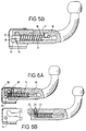
- FIG. 6A, 6B Another embodiment of the towing bracket is partly shown in Figures 6A, 6B and comprises similar parts as the towing bracket shown in Figures 5A, 5B, but is completed so that the pin-like, axially displaceable locking member formed by the clamping body 12, the mentioned, first pin 13 and the rack 18 remains in the retracted position when the ball bar is detached, because in this position a pin 20, which moves radially within the pin-like locking member, moves outwards under the influence of spring force and thus projects into a bore 21 in the ball bar, pushing another pin 22 present within the ball bar outwards until it strikes a stop.
- the ball bar is attached again said latter pin 22 is pushed back automatically as a result of making contact with the housing, after which the pin-like locking member moves back automatically again into the locking position under the influence of spring force.
- the cylindrical pin 13, the clamping body 12 formed by a head of the pin 13 and having a wedge-shaped end and the rack 18 shown in Figures 6A, 6B may for instance be formed or be replaced by the locking pin, i.e. pin-like locking member shown in Figures 7A, 7B or by the locking pin, i.e. pin-like locking member shown in Fig. 7C.
- Each of these locking members comprises a head disposed at one end. This head has a cylindrical portion and a wedge-shaped free end and forms the clamping body.
- at least the wedge-shaped end thereof is formed of a hard metal by means of machining (Fig. 7C) or by the so-called MIM process ( Figures 7A, 7B).
- Both methods result in a hard wedge-shaped end of the pin-like locking member having the required strength.
- This hard product is then placed in a die-casting mould and completed to a pin-like locking member by forming - i.e. casting - a plastic or a suitable metal alloy thereon.
- the MIM process - i.e. metal injection moulding process - is a rather new process, which comprises the following steps:
Landscapes
- Engineering & Computer Science (AREA)
- Transportation (AREA)
- Mechanical Engineering (AREA)
- Clamps And Clips (AREA)
- Harvester Elements (AREA)
- Soil Working Implements (AREA)
- Fittings On The Vehicle Exterior For Carrying Loads, And Devices For Holding Or Mounting Articles (AREA)
- Handcart (AREA)
Abstract
Description
- The invention relates to a detachable towing bracket for a vehicle, whereby the bracket has a ball bar comprising a first coupling means which can be detachably connected to a second coupling means comprising preferably a housing to be secured to the vehicle, whereby the connection can be automatically stabilized and secured when said ball bar comprising first coupling means is inserted or attached.
- A towing bracket of this type is known from EP 0223996. With the known towing bracket the first and the second coupling means are interconnected by pressing together two pairs of corresponding surfaces (made up of two cylindrical cams and two cylindrical recesses) and two pairs of contra corresponding surfaces, which make line contact with each other. The two coupling means thus contact one another at four contacts, i.e. two conformable surface contacts and two line contacts, said contacts providing together a more or less statically defined connection.
- The towing bracket according to the above-mentioned patent has two drawbacks, namely:
- Since the support is statically defined, the stability of the coupling is not optimal.
- The construction as a whole is rather complex and cannot be manufactured in an inexpensive manner. By way of illustration the cast-iron housing may be mentioned here, which requires machining operations, as well as the ball bar, which is made from square bar material by means of a metal-removing operation.
- The object of the invention is to provide a detachable towing bracket having two coupling means which can be ideally interconnected, that is, without play and with a high degree of stability. It shall preferably also be possible to manufacture the towing bracket in a simple and inexpensive manner.
- This object is achieved according to the invention by a towing bracket having the characteristics of claim 1.
- The invention also relates to a method for manufacturing a towing bracket, wherein this method has the characteristics of
claim 20 according to the invention. - According to the invention, the two coupling means can be brought into a connected position in which they contact one another at seven contact points or line contacts so that a statically overdefined connection results which is very stable.
- When the two coupling means are brought into the connected position, the clamping body is supported and so to say pushed off by the second coupling means so that the clamping body presses the cams against abutting surfaces in or on the second coupling means which comprises preferably a housing.
- Preferably said six fixed contact points or line contacts are distributed over two plano-parallel planes, three in each plane, which plano-parallel planes are disposed on either side of said first coupling means, whilst the seventh contact point or line contacts, which is formed by the clamping body pressing the two coupling means together, is positioned centrally between the two plano-parallel planes.
- Preferably said seven contact points or line contacts are line contacts, which ensures a sufficient load-bearing capacity without having to subject the materials to special hardening processes.
- The subject of the invention is subsequently illustrated with reference to embodiments shown in the drawings. In the drawings,
- Fig. 1 shows a schematic, oblique view of parts of a towing bracket having a first coupling means provided with three cams on either side and a second coupling means in separated positions, an oblique view of said parts of the towing bracket wherein the first and second coupling means are in the connected position, a schematic side view of the cams of the first coupling means and of a housing part of the second coupling means and an end view of the housing part,
- Fig. 2 shows analogous views as Fig. 1 of a towing bracket having a first coupling means provided with two cams on either side,
- Fig. 3 shows a plate in various manufacturing states for forming a housing of the second coupling means,
- Fig. 4A is a schematic representation of a towing bracket having a pivotable clamping body, partly in longitudinal section and partly in elevation,
- Fig. 4B is an elevation of a rotary mechanism having a rotary knob of the towing brackets shown in Fig. 4A,
- Figs 4C is an elevation of the rotary mechanism shown in Fig. 4B, but in another axial position of the rotary knob,
- Fig. 5A is a schematic representation of a towing bar and first coupling means having an axially displaceable clamping body, partly in longitudinal section and partly in elevation,
- Fig. 5B is a schematic representation of a towing bracket comprising the first coupling means shown in Fig. 5A, partly in longitudinal section and partly in elevation,
- Fig. 6A is a schematic representation of another towing bracket having an axially displaceable clamping body in the connected position,
- Fig. 6B shows the towing bracket of Fig. 6A, but in separate positions of the first and second coupling means,
- Fig. 7A is a longitudinal section through a locking member comprising a displaceable clamping body connected to a displaceable pin and a rack,
- Fig. 7B is a view of the underside of the locking member according to Fig. 6A and
- Fig. 7C is a longitudinal section through another locking member having a displaceable clamping body and a displaceable pin and a rack.
-
- The embodiments of detachable towing brackets for a vehicle shown in the Figures 1 and 2 have a ball bar comprising a first coupling means which can be detachably connected to a second coupling means mounted on the vehicle. The first coupling means has a clamping body and cams. The second coupling means has a housing. When the two coupling means are connected to one another, the fixation takes place over seven contact points or line contacts K1, K2, K3, K4, K5, K6, K7. The contact point or line contact K7 is defined by the clamping body which itself can't be seen in the Figures 1 and 2. The clamping body is disposed in or on the other parts of the first coupling means, rests against and/or pushes off against the second coupling means at the contact point or line contact K7 and presses the cams against abutting surfaces on or in the second coupling means at the contact points or line contacts K1 - K6.
- The embodiment of the towing bracket according to the invention shown in Fig. 1 has six fixed contact points or line contacts K1, K2, K3, K4, K5, K6 which are formed by a number of cams, namely six, which are located on said first coupling means and which are positioned such that they are arranged in pairs on one axis. The cams are pressed against six abutting surfaces in the housing of the second coupling means when the first and the second coupling means are in the connected position. Slots are provided in the two lateral surfaces or walls of the housing, said slots forming the stop surfaces for all cams. Said slots are preferably configured to receive and guide the two front cams when the ball bar is being attached, whilst the four rear cams are unable to pass the funnel-shaped entry of the slots.
- In the embodiment of the towing bracket shown in Fig. 2 a simplification of the production process is realized by replacing the four rear cams by two cams which are dimensioned such that they are unable to pass the funnel-shaped entry of the slots, but are pressed against said entry when the ball bar is being attached, whereby four line contacts are formed.
- The part of the housings shown in Figures 1, 2 is formed from a steel plate by means of fine-blanking and bending operations, whereby the guide slots are punched out during the blanking operation. This is illustrated in Fig. 3 in which the numerals 3.1, 3.2, 3.3 designate various manufacturing states of the plate.
- One embodiment of the towing bracket shown in Figures 4A, 4B, 4C is characterized in that said clamping body is an eccentric cam 1, which can be rotated by a
rack 2, which engages teeth provided thereon. Said rack is positioned on the end of a cylindrical pin 3, which can move axially in the ball bar or the first coupling means, whereby said pin is driven by a spring 4 (when locking takes place automatically) or by atoothed wheel 5, which cooperates with a rack 6 provided on the other end of said pin (when unlocking takes place manually). In this embodiment the so-called first locking is effected by the cam profile, which in addition to having a part which provides the tightening effect by comprising arun-on angle" or a run-on surface of a certain number of degrees, also has a part comprising a "run-on angle" or a run-on surface of zero degrees. As a result of the presence of said zero degree surface any reverse rotation of the eccentric cam in the unlocking direction caused by the forces acting on the ball bar will be stopped automatically as soon as said eccentric cam arrives at said zero degree surface. The so-called second locking is provided by the rotary knob mechanism, because of the fact that the
rotary knob 7 cannot make a complete turn against a spring force until it is depressed. In the extended position of the rotary knob (which is shown in Fig. 4B and into which position the knob springs automatically under the effect of a spring force when the ball bar is being attached), therotary knob 7 is blocked against rotation as a result of alocking cam 8 provided on theshaft 9 engaging in anarcuate slot 10 of the thelock plate 11. When the knob is depressed by hand into the position shown in Fig. 4C the drive shaft will move in axial direction and said locking cam is released from theslot 10, after which therotary knob 7 can be turned. - One embodiment of the towing bracket shown partly in Fig. 5A and in Fig. 5B is characterized in that the clamping
body 12 is an axially movable head which is fixedly connected to the end of acylindrical pin 13 or forms part thereof and has a cylindrical portion and a wedge-shaped end. The clampingbody 12 can upon axial movement of thepin 13 push off with its sloping run-onsurface 14 against apin 15 present within the housing. The displaceable pin (13) is driven by a spring 16 (when locking takes place automatically) or by atoothed member 17 which forms a part of a toothed wheel and engages arack 18 provided on the other end of the displaceable pin 13 (when locking takes place manually). Said toothed wheel ortoothed member 17 is connected to thecontrol knob 7 via the drive shaft (9). The first locking is effected because the wedge angle of a certain number of degrees (approx. 12 degrees) on the operative part of the run-onsurface 14 slowly decreases to zero degrees at theend 19 of the run-onsurface 14. This tapering (to a possible angle of zero degrees) ensures that when the forces acting on the ball bar should cause the wedge to move in axial direction, this movement is stopped automatically when the wedge angle has sufficiently decreased (to possibly zero degrees). The so-called second locking is achieved by the rotary knob mechanism described already with reference to the figures 4A, 4B, 4C. - Another embodiment of the towing bracket is partly shown in Figures 6A, 6B and comprises similar parts as the towing bracket shown in Figures 5A, 5B, but is completed so that the pin-like, axially displaceable locking member formed by the clamping
body 12, the mentioned,first pin 13 and therack 18 remains in the retracted position when the ball bar is detached, because in this position apin 20, which moves radially within the pin-like locking member, moves outwards under the influence of spring force and thus projects into abore 21 in the ball bar, pushing anotherpin 22 present within the ball bar outwards until it strikes a stop. When the ball bar is attached again saidlatter pin 22 is pushed back automatically as a result of making contact with the housing, after which the pin-like locking member moves back automatically again into the locking position under the influence of spring force. - The
cylindrical pin 13, the clampingbody 12 formed by a head of thepin 13 and having a wedge-shaped end and therack 18 shown in Figures 6A, 6B may for instance be formed or be replaced by the locking pin, i.e. pin-like locking member shown in Figures 7A, 7B or by the locking pin, i.e. pin-like locking member shown in Fig. 7C. Each of these locking members comprises a head disposed at one end. This head has a cylindrical portion and a wedge-shaped free end and forms the clamping body. For manufacturing the locking pin or pin-like locking member, at least the wedge-shaped end thereof is formed of a hard metal by means of machining (Fig. 7C) or by the so-called MIM process (Figures 7A, 7B). Both methods result in a hard wedge-shaped end of the pin-like locking member having the required strength. This hard product is then placed in a die-casting mould and completed to a pin-like locking member by forming - i.e. casting - a plastic or a suitable metal alloy thereon. - The MIM process - i.e. metal injection moulding process - is a rather new process, which comprises the following steps:
- 1) Granulated material consisting of a mixture of a suitable metal powder and a suitable plastic is formed into a first intermediate product by means of the so-called metal injection moulding process.
- 2) The first intermediate product formed under 1 is then immersed in a chemical bath, in which the plastic material present in the product is dissolved and removed again.
- 3) The porous, second intermediate product thus formed is sintered under a vacuum at a high temperature, whereby the porosity is lost and the material attains a density of nearly 100%. As a result of this nearly 100% density the properties of the material are practically identical to those of the original material i.e metal. In this manner a very hard and strong final product can be obtained without any metal removing operations being required.
-
Claims (24)
- A detachable towing bracket for a vehicle, having a ball bar comprising a first coupling means and a second coupling means configured to be mounted on the vehicle, wherein the two coupling means can be brought into a connected position in which they are detachably connected to one another, wherein the first coupling means comprises a clamping body (1, 12) and cams, wherein the clamping body (1, 12) rests against the second coupling means at a contact point or line contact (K7) in said connected position so that the cams are pressed against abutting surfaces of the second coupling means at contact points or line contacts (K1, K2, K3, K4, K5, K6) in said connected position, characterised in that the cams define six of said contact points or line contacts (K1, K2, K3, K4, K5, K6) and that the two coupling means contact one another at seven contact points or line contacts (K1, K2, K3, K4, K5, K6, K7) in said connected position so that a statically overdefined connection between the two coupling means is obtained.
- A towing bracket according to claim 1, characterised in that the first coupling means has two opposite sides, that two or three cams having an axis are disposed on either side of the first coupling means and that each cam is positioned such that its axis is aligned with the axis of a cam on the other side of the first coupling means (Figures 1 or 2).
- A towing bracket according to claim 2, characterised in that the first coupling means comprises a front cam and two rear cams on each of said two sides of the first coupling means, that the second coupling means comprises a housing having slots provided in two lateral surfaces, that each slot has a funnel-shaped entry and a guide portion and forms the abutting surfaces for the cams, that the guide portions of the slots are configured to receive and guide the two front cams and that the four rear cams are disposed such that they are unable to pass the funnel-shaped entries, but abut against these entries in said connected position (Figure 1).
- A towing bracket according to claim 2, characterised in that a front cam and a rear cam are disposed on each of said two sides of the first coupling means, that the second coupling means comprises a housing having slots provided in two lateral surfaces, that each slot has a funnel-shaped entry and a guide portion and forms the abutting surfaces for the cams, that the guide portions of the slots are configured to receive and guide the two front cams, that the two rear cams are dimensioned such that they are unable to pass the funnel-shaped entries of the slots, but are pressed against the entries in said connected position and that each rear cam defines two of the contact points or line contacts (K1, K2, K3, K4, K5, K6, K7).
- A towing bracket according to any of claims 1 to 4, characterised in that the second coupling means comprises a housing having two lateral walls which are opposite to one another and comprise slots forming the abutting surfaces for the cams, that the clamping body (1, 12) is pivotable or displaceable relative to the ball bar and that the contact point or line contact (K7) defined by the clamping body (1, 12) is located between the two lateral walls (Figures 1, 2, 4A, 5B, 6A, 6B).
- A towing bracket according to claim 5, characterised in that each lateral wall has a plane portion and an entry portion, that the plane portions are parallel to one another, that the entry portions of the lateral walls are projecting away from the plane portions and from one another, that each slot forms, in said connected position together with two or three of the cams, three of the contact points or line contacts (K1 - K7) and has a guide portion and an entry, that the guide portions are disposed substantially within the plane wall portions and that the entries of the slots are disposed in transitions between the plane portions and the entry portions of the lateral walls and/or adjacent to these transitions (Figures 1, 2, 3).
- A towing bracket according to claim 5 or 6, characterised in that the second coupling means comprises a pin (15) disposed within the housing and forming in said connected position together with the clamping body (12) the contact point or line contact associated with the clamping body (12).
- A towing bracket according to any of claims 3 to 7, characterised in that the two lateral walls and a wall connecting the two lateral walls are formed together of a one-piece plate.
- A towing bracket according to any of claims 3 to 8, characterised in that said housing comprises a steel plate which has been shaped by blanking, for instance fine-blanking, and bending and has been provided with said slots by punching.
- A towing bracket according to any of claims 1 to 6 or 8 or 9, characterised in that the clamping body consists of a pivotable eccentric cam (1) having teeth, that the first coupling means is provided with a first rack (2), a cylindrical, displaceable pin (3), a spring (4), a toothed member (5), a second rack (6) and a rotary mechanism, that the pin (3) is axially displaceable with respect to the ball bar, that the two racks (2, 6) are positioned on opposite ends of the pin (3), that the first rack (2) engages the teeth of the pivotable cam (1) so that the latter can be pivoted by the rack (2), that the spring (4) is configured to drive the racks (2, 6) and the pin (3) for automatically locking the first coupling means with respect to the second coupling means when the two coupling means are moved into the connected position and that the rotary mechanism is in operative connection with the second rack (6) to make it possible to displace the pin (3) and to unlock the two coupling means by manually operating the rotary mechanism (Figures 4A, 4B, 4C).
- A towing bracket according to any of claims 1 to 9, characterised in that the first coupling means is provided with a cylindrical, displaceable pin (13) axially displaceable with respect to the ball bar, a rack (18) and a spring (16) and a rotary mechanism, that the clamping body (12) is fixedly connected to the displaceable pin (13) and has a wedge-shaped portion comprising a run-on surface (14) which is at least in part sloping relative to the direction of displacement of the displaceable pin (13) and configured to engage a pin (15) disposed within a housing of the second coupling means, that the spring (16) is configured to drive the clamping body (12) and the displaceable pin (13) for locking the first coupling means with respect to the second coupling means automatically when the two coupling means are moved into the connected position, that the rack (18) is disposed on an end of the displaceable pin (13) facing away from the clamping body (12) and that the rotary mechanism is in operative connection with the rack (18) to make it possible to displace the clamping body (12) by manually operating the rotary mechanism (Figures 5B, 6A, 6B, 7A, 7B, 7C).
- A towing bracket according to claim 11, characterised in that the displaceable pin (13) and the rack (18) have been formed by casting a plastic or a metal alloy onto the clamping body (12) within a die-casting mould.
- A towing bracket according to claim 11 or 12, characterised in that the wedge-shaped portion of the clamping body (12) consists of hard metal.
- A towing bracket according any of claims 11 to 13, characterised in that the wedge-shaped portion of the clamping body (12) has been made by a metal injection moulding (MIM) process.
- A towing bracket according to any of claims 10 to 14, characterised in that the first coupling means comprises a lock plate (11), that the rotary mechanism comprises a rotary knob (7), a drive shaft (9) secured to the latter, a locking cam (8) provided on the drive shaft (9), a toothed member (5, 17) connected to the drive shaft (9) and engaging the rack (6, 18) being in operative connection with the rotary mechanism and a lock spring for urging the locking cam (8) towards a locking position, that the locking cam (8) is configured to engage the lock plate (11) in the locking position for securing the drive shaft (9) against rotation and that the locking cam (8) is further configured such that it can be released from the lock plate (11) by depressing the knob (7) against a spring force produced by the lock spring, wherein the locking cam engages in the locking position for instance into a slot (10) of the lock plate (11) (Figures 4B, 4C, 5A).
- A towing bracket according to claim 15, characterised in that the drive shaft (9), the toothed member (17) and the locking cam have been made by injection moulding or by a metal injection moulding (MIM) process (Figures 4A, 4B, 4C, 5A, 5B).
- A towing bracket according to any of claims 1 to 16, characterised in that the first coupling means comprises a displaceable pin (3, 13), a spring (4) and a rotary mechanism, that the displaceable pin (3, 13) is displaceable in axial direction of the ball bar relative to the latter, that the clamping body (1, 12) is movable relative to the ball bar by means of the displaceable pin (3, 13) and/or rigidly connected to the latter, that the spring (4) is configured to drive the displaceable pin (3, 13) towards a locking position in which the clamping body (1, 12) locks the first coupling means when the two coupling means are in the connected position, that the rotary mechanism is in operative connection with the displaceable pin (3, 13) for displacing the latter from said locking position to a retracted position by manually operating the rotary mechanism, that the displaceable pin (3, 13) and/or the clamping body (12) holds a movable member (20) which is movable radially to the pin (3, 13), that a spring means is provided which exerts an outwards directed spring force onto said movable member (20) so that the latter projects in said retracted position into a bore (21) of the ball bar for locking the displaceable pin (3, 13) in said retracted position and pushes thereby another movable member (22) held in the bore (21) of the ball bar outwards and that this other movable member is configured such that it is pushed back by the second coupling means and pushes in its turn the movable member (20) held by the displaceable pin (3, 13) out of the bore (21) of the ball bar while the first coupling means is moved into the connected position.
- A towing bar according to claim 17, characterised in that the displaceable pin (3, 13) is disposed within the ball bar and that the two movable members are pins (20, 22).
- A towing bar according to any of claims 1 to 18, characterised in that the second coupling means comprises a housing and that the ball bar comprises a portion having a round cross-section and an end portion flattened to such a width that the end portion can be received within the housing.
- A method for manufacturing a detachable towing bracket for a vehicle, having a ball bar comprising a first coupling means and a second coupling means comprising a housing and configured to be mounted on the vehicle, wherein the two coupling means can be brought into a connected position in which they are detachably connected to one another, wherein the first coupling means comprises a clamping body (1, 12) and cams, wherein the clamping body (1, 12) rests against the housing at a contact point or line contact (K7) in said connected position so that the cams are pressed against abutting surfaces of the housing at contact points or line contacts (K1, K2, K3, K4, K5, K6) in said connected position, characterised in that the cams define six of said contact points or line contacts (K1, K2, K3, K4, K5, K6, K7), that the two coupling means contact one another at seven contact points or line contacts (K1, K2, K3, K4, K5, K6, K7) in said connected position so that a statically overdefined connection between the two coupling means is obtained, that the housing comprises two lateral walls or surfaces having slots forming the abutting surfaces for the cams and that a steel plate is made by blanking, provided with slots by punching and bent so as to form the two lateral walls or surfaces of the housing.
- A method according to claim 20, characterised in that the blanking of the steel plate is fine-blanking.
- A method according to claim 20 or 21, characterised in that the first clamping means comprises a cylindrical pin (13) axially displaceable with respect to the ball bar and a rack (18), that the clamping body (12) is placed in a die-casting mould and that the pin (13) and the rack (18) are then formed by casting a metal alloy or a plastic onto the clamping body (12) within the mould.
- A method according to claim 22 characterised in that the clamping body (12) is made by a metal injection moulding (MIM) process.
- A method according to claim 23, characterised in that a mixture of a metal powder and of a plastic is formed for the metal injection moulding (MIM) process, that the mixture is injected into a mould so that a first intermediate product is formed, that the plastic is removed so that a second, porous intermediate product is formed and that the latter is sintered so as to form the clamping body (12).
Applications Claiming Priority (4)
| Application Number | Priority Date | Filing Date | Title |
|---|---|---|---|
| NL9401471A NL9401471A (en) | 1994-09-09 | 1994-09-09 | Detachable towbar. |
| NL9401471 | 1994-09-09 | ||
| NL1000550 | 1995-06-13 | ||
| NL1000550A NL1000550C1 (en) | 1995-06-13 | 1995-06-13 | Detachable towbar. |
Publications (2)
| Publication Number | Publication Date |
|---|---|
| EP0700799A1 EP0700799A1 (en) | 1996-03-13 |
| EP0700799B1 true EP0700799B1 (en) | 1999-11-17 |
Family
ID=26642096
Family Applications (1)
| Application Number | Title | Priority Date | Filing Date |
|---|---|---|---|
| EP95202457A Expired - Lifetime EP0700799B1 (en) | 1994-09-09 | 1995-09-11 | Detachable towing bracket and method for manufacturing such a bracket |
Country Status (4)
| Country | Link |
|---|---|
| EP (1) | EP0700799B1 (en) |
| AT (1) | ATE186683T1 (en) |
| DE (1) | DE69513349T2 (en) |
| ES (1) | ES2139832T3 (en) |
Families Citing this family (6)
| Publication number | Priority date | Publication date | Assignee | Title |
|---|---|---|---|---|
| NL1008214C2 (en) * | 1998-02-05 | 1999-08-06 | Brink Bv | Suspension or trailer assembly. |
| WO1999044844A1 (en) * | 1998-03-05 | 1999-09-10 | Kalabis - Bělá | Towing device |
| DE10153490A1 (en) * | 2001-10-24 | 2003-05-15 | Oris Fahrzeugteile Riehle H | Trailer coupling for vehicle has injection molded operating rod made of plastic |
| DE102005040181A1 (en) * | 2005-08-25 | 2007-03-01 | Westfalia-Automotive Gmbh | Towbar for motor vehicles |
| EP2058151A1 (en) * | 2007-11-08 | 2009-05-13 | Hnos. Sanchez-Lafuente, S.A. | Detachable tow hitch on vehicle |
| DE202008016077U1 (en) | 2008-12-04 | 2009-02-19 | Mvg-Metallverarbeitungsgesellschaft Mbh | Trailer coupling and ball bar of a trailer hitch |
Family Cites Families (6)
| Publication number | Priority date | Publication date | Assignee | Title |
|---|---|---|---|---|
| NL168452C (en) * | 1977-05-11 | 1982-04-16 | Brink Bv | TOWBAR DEVICE FITTED WITH A REMOVABLE TOWBAR WITH A BALL JOINT. |
| DE3666187D1 (en) * | 1985-11-23 | 1989-11-16 | Dickmann Thomas | Towing device for vehicles |
| DE8813812U1 (en) * | 1988-11-04 | 1988-12-29 | Peka-Fahrzeugbau Gmbh + Co Kg, 7500 Karlsruhe | Removable trailer coupling |
| DE4022764C2 (en) * | 1990-07-18 | 1998-01-29 | Eberhardt Peka Fahrzeug | Removable trailer attachment |
| DE4041796C1 (en) * | 1990-12-24 | 1992-06-25 | Oris-Metallbau Kg Hans Riehle, 7141 Moeglingen, De | |
| DE4235843C2 (en) * | 1992-10-23 | 1996-07-11 | Mvg Metallverarbeitunggesellsc | Trailer coupling |
-
1995
- 1995-09-11 EP EP95202457A patent/EP0700799B1/en not_active Expired - Lifetime
- 1995-09-11 ES ES95202457T patent/ES2139832T3/en not_active Expired - Lifetime
- 1995-09-11 DE DE69513349T patent/DE69513349T2/en not_active Expired - Lifetime
- 1995-09-11 AT AT95202457T patent/ATE186683T1/en active
Also Published As
| Publication number | Publication date |
|---|---|
| DE69513349D1 (en) | 1999-12-23 |
| EP0700799A1 (en) | 1996-03-13 |
| ES2139832T3 (en) | 2000-02-16 |
| DE69513349T2 (en) | 2000-05-11 |
| ATE186683T1 (en) | 1999-12-15 |
Similar Documents
| Publication | Publication Date | Title |
|---|---|---|
| US8251623B2 (en) | System for fixing a seat, in particular an aircraft seat, and seat including such a system | |
| DE69004646T2 (en) | Closure device with a ramp tongue. | |
| DE69728809T2 (en) | Connecting arrangement in a plug | |
| EP0390089A2 (en) | Steering wheel lock device | |
| KR20050037351A (en) | Headrest lock structure with lock slots, method for forming lock slots in headrest pole and method for producing headrest pole | |
| DE4443349C2 (en) | Electrical connector | |
| DE3106952A1 (en) | METAL MOLD FOR MOLDING A HOLLOW BODY WITH INWARD-INCLINED SIDEWALL | |
| JPH09501477A (en) | Locking system especially for vehicles and building equipment | |
| US20020020244A1 (en) | Fine increment tilt mechanism | |
| DE10126132A1 (en) | Switching device for vehicles | |
| EP0095691B1 (en) | Cylinder lock, particularly for vehicle steering mechanisms | |
| DE102020107055A1 (en) | Solenoid valve assembly, and method of replacing a diaphragm | |
| EP1974866B1 (en) | Spindle lock for a handheld drilling and chiselling hammer | |
| DE10131936A1 (en) | Connector holding mechanism | |
| DE69308480T2 (en) | Modular franking machine with a device for assembling and for automatic locking and centering of modules | |
| EP0700799A1 (en) | Detachable towing bracket | |
| EP1079987A1 (en) | Removable motor vehicle seat | |
| DE69232258T2 (en) | ELECTRICAL CONNECTING DEVICE WITH MODULE EJECTOR | |
| DE2335879A1 (en) | ELECTRIC SWITCH | |
| DE3724705A1 (en) | Safety blocking lock for motor vehicles | |
| JP3615613B2 (en) | Injection mold | |
| EP2811855A1 (en) | Belt buckle with release lock | |
| JP2001504981A (en) | Safety switch | |
| DE3243191A1 (en) | METHOD FOR PRODUCING A COMMUTATOR RING FOR A COMMUTATOR | |
| EP1868858B1 (en) | Device for starting and operating an engine in a motor vehicle |
Legal Events
| Date | Code | Title | Description |
|---|---|---|---|
| PUAI | Public reference made under article 153(3) epc to a published international application that has entered the european phase |
Free format text: ORIGINAL CODE: 0009012 |
|
| AK | Designated contracting states |
Kind code of ref document: A1 Designated state(s): AT BE CH DE ES FR GB IT LI NL SE |
|
| RAP1 | Party data changed (applicant data changed or rights of an application transferred) |
Owner name: SCAMBIA INDUSTRIAL DEVELOPMENTS AKTIENGESELLSCHAFT |
|
| 17P | Request for examination filed |
Effective date: 19960902 |
|
| 17Q | First examination report despatched |
Effective date: 19970814 |
|
| GRAG | Despatch of communication of intention to grant |
Free format text: ORIGINAL CODE: EPIDOS AGRA |
|
| GRAG | Despatch of communication of intention to grant |
Free format text: ORIGINAL CODE: EPIDOS AGRA |
|
| GRAG | Despatch of communication of intention to grant |
Free format text: ORIGINAL CODE: EPIDOS AGRA |
|
| GRAH | Despatch of communication of intention to grant a patent |
Free format text: ORIGINAL CODE: EPIDOS IGRA |
|
| GRAH | Despatch of communication of intention to grant a patent |
Free format text: ORIGINAL CODE: EPIDOS IGRA |
|
| GRAA | (expected) grant |
Free format text: ORIGINAL CODE: 0009210 |
|
| AK | Designated contracting states |
Kind code of ref document: B1 Designated state(s): AT BE CH DE ES FR GB IT LI NL SE |
|
| PG25 | Lapsed in a contracting state [announced via postgrant information from national office to epo] |
Ref country code: SE Free format text: THE PATENT HAS BEEN ANNULLED BY A DECISION OF A NATIONAL AUTHORITY Effective date: 19991117 Ref country code: AT Free format text: LAPSE BECAUSE OF FAILURE TO SUBMIT A TRANSLATION OF THE DESCRIPTION OR TO PAY THE FEE WITHIN THE PRESCRIBED TIME-LIMIT Effective date: 19991117 |
|
| REF | Corresponds to: |
Ref document number: 186683 Country of ref document: AT Date of ref document: 19991215 Kind code of ref document: T |
|
| REG | Reference to a national code |
Ref country code: CH Ref legal event code: EP |
|
| REG | Reference to a national code |
Ref country code: CH Ref legal event code: NV Representative=s name: PATENTANWALTSBUERO EDER AG |
|
| REF | Corresponds to: |
Ref document number: 69513349 Country of ref document: DE Date of ref document: 19991223 |
|
| ET | Fr: translation filed | ||
| ITF | It: translation for a ep patent filed | ||
| REG | Reference to a national code |
Ref country code: ES Ref legal event code: FG2A Ref document number: 2139832 Country of ref document: ES Kind code of ref document: T3 |
|
| PLBE | No opposition filed within time limit |
Free format text: ORIGINAL CODE: 0009261 |
|
| STAA | Information on the status of an ep patent application or granted ep patent |
Free format text: STATUS: NO OPPOSITION FILED WITHIN TIME LIMIT |
|
| 26N | No opposition filed | ||
| PGFP | Annual fee paid to national office [announced via postgrant information from national office to epo] |
Ref country code: CH Payment date: 20010924 Year of fee payment: 7 |
|
| REG | Reference to a national code |
Ref country code: GB Ref legal event code: IF02 |
|
| PG25 | Lapsed in a contracting state [announced via postgrant information from national office to epo] |
Ref country code: LI Free format text: LAPSE BECAUSE OF NON-PAYMENT OF DUE FEES Effective date: 20020930 Ref country code: CH Free format text: LAPSE BECAUSE OF NON-PAYMENT OF DUE FEES Effective date: 20020930 |
|
| REG | Reference to a national code |
Ref country code: CH Ref legal event code: PL |
|
| PGFP | Annual fee paid to national office [announced via postgrant information from national office to epo] |
Ref country code: ES Payment date: 20030930 Year of fee payment: 9 |
|
| PGFP | Annual fee paid to national office [announced via postgrant information from national office to epo] |
Ref country code: GB Payment date: 20040827 Year of fee payment: 10 |
|
| PG25 | Lapsed in a contracting state [announced via postgrant information from national office to epo] |
Ref country code: ES Free format text: LAPSE BECAUSE OF NON-PAYMENT OF DUE FEES Effective date: 20040913 |
|
| PG25 | Lapsed in a contracting state [announced via postgrant information from national office to epo] |
Ref country code: IT Free format text: LAPSE BECAUSE OF NON-PAYMENT OF DUE FEES Effective date: 20050911 Ref country code: GB Free format text: LAPSE BECAUSE OF NON-PAYMENT OF DUE FEES Effective date: 20050911 |
|
| REG | Reference to a national code |
Ref country code: ES Ref legal event code: FD2A Effective date: 20040913 |
|
| GBPC | Gb: european patent ceased through non-payment of renewal fee |
Effective date: 20050911 |
|
| PGFP | Annual fee paid to national office [announced via postgrant information from national office to epo] |
Ref country code: FR Payment date: 20100921 Year of fee payment: 16 |
|
| PGFP | Annual fee paid to national office [announced via postgrant information from national office to epo] |
Ref country code: NL Payment date: 20100910 Year of fee payment: 16 |
|
| PGFP | Annual fee paid to national office [announced via postgrant information from national office to epo] |
Ref country code: DE Payment date: 20100908 Year of fee payment: 16 Ref country code: BE Payment date: 20100915 Year of fee payment: 16 |
|
| BERE | Be: lapsed |
Owner name: *SCAMBIA INDUSTRIAL DEVELOPMENTS A.G. Effective date: 20110930 |
|
| REG | Reference to a national code |
Ref country code: NL Ref legal event code: V1 Effective date: 20120401 |
|
| REG | Reference to a national code |
Ref country code: FR Ref legal event code: ST Effective date: 20120531 |
|
| PG25 | Lapsed in a contracting state [announced via postgrant information from national office to epo] |
Ref country code: BE Free format text: LAPSE BECAUSE OF NON-PAYMENT OF DUE FEES Effective date: 20110930 |
|
| REG | Reference to a national code |
Ref country code: DE Ref legal event code: R119 Ref document number: 69513349 Country of ref document: DE Effective date: 20120403 |
|
| PG25 | Lapsed in a contracting state [announced via postgrant information from national office to epo] |
Ref country code: DE Free format text: LAPSE BECAUSE OF NON-PAYMENT OF DUE FEES Effective date: 20120403 Ref country code: NL Free format text: LAPSE BECAUSE OF NON-PAYMENT OF DUE FEES Effective date: 20120401 |
|
| PG25 | Lapsed in a contracting state [announced via postgrant information from national office to epo] |
Ref country code: FR Free format text: LAPSE BECAUSE OF NON-PAYMENT OF DUE FEES Effective date: 20110930 |