EP0700750B1 - Apparatus for attaching self-piercing nuts to a panel - Google Patents
Apparatus for attaching self-piercing nuts to a panel Download PDFInfo
- Publication number
- EP0700750B1 EP0700750B1 EP95306109A EP95306109A EP0700750B1 EP 0700750 B1 EP0700750 B1 EP 0700750B1 EP 95306109 A EP95306109 A EP 95306109A EP 95306109 A EP95306109 A EP 95306109A EP 0700750 B1 EP0700750 B1 EP 0700750B1
- Authority
- EP
- European Patent Office
- Prior art keywords
- punch
- nut
- panel
- holder
- piercing
- Prior art date
- Legal status (The legal status is an assumption and is not a legal conclusion. Google has not performed a legal analysis and makes no representation as to the accuracy of the status listed.)
- Expired - Lifetime
Links
- 239000002184 metal Substances 0.000 claims description 8
- 238000003825 pressing Methods 0.000 description 8
- 238000004519 manufacturing process Methods 0.000 description 2
- 239000011796 hollow space material Substances 0.000 description 1
- 238000004080 punching Methods 0.000 description 1
Images



Classifications
-
- B—PERFORMING OPERATIONS; TRANSPORTING
- B23—MACHINE TOOLS; METAL-WORKING NOT OTHERWISE PROVIDED FOR
- B23P—METAL-WORKING NOT OTHERWISE PROVIDED FOR; COMBINED OPERATIONS; UNIVERSAL MACHINE TOOLS
- B23P19/00—Machines for simply fitting together or separating metal parts or objects, or metal and non-metal parts, whether or not involving some deformation; Tools or devices therefor so far as not provided for in other classes
- B23P19/04—Machines for simply fitting together or separating metal parts or objects, or metal and non-metal parts, whether or not involving some deformation; Tools or devices therefor so far as not provided for in other classes for assembling or disassembling parts
- B23P19/06—Screw or nut setting or loosening machines
- B23P19/062—Pierce nut setting machines
-
- Y—GENERAL TAGGING OF NEW TECHNOLOGICAL DEVELOPMENTS; GENERAL TAGGING OF CROSS-SECTIONAL TECHNOLOGIES SPANNING OVER SEVERAL SECTIONS OF THE IPC; TECHNICAL SUBJECTS COVERED BY FORMER USPC CROSS-REFERENCE ART COLLECTIONS [XRACs] AND DIGESTS
- Y10—TECHNICAL SUBJECTS COVERED BY FORMER USPC
- Y10T—TECHNICAL SUBJECTS COVERED BY FORMER US CLASSIFICATION
- Y10T29/00—Metal working
- Y10T29/53—Means to assemble or disassemble
- Y10T29/5343—Means to drive self-piercing work part
-
- Y—GENERAL TAGGING OF NEW TECHNOLOGICAL DEVELOPMENTS; GENERAL TAGGING OF CROSS-SECTIONAL TECHNOLOGIES SPANNING OVER SEVERAL SECTIONS OF THE IPC; TECHNICAL SUBJECTS COVERED BY FORMER USPC CROSS-REFERENCE ART COLLECTIONS [XRACs] AND DIGESTS
- Y10—TECHNICAL SUBJECTS COVERED BY FORMER USPC
- Y10T—TECHNICAL SUBJECTS COVERED BY FORMER US CLASSIFICATION
- Y10T29/00—Metal working
- Y10T29/53—Means to assemble or disassemble
- Y10T29/53478—Means to assemble or disassemble with magazine supply
- Y10T29/53522—Means to fasten by deforming
Definitions
- the invention relates to apparatus for attaching self-piercing nuts to one side of a panel such as a metal plate.
- each nut driven by a punch has an end face to cooperate with a piercing-caulking die located on the other side of the panel and in alignment with the nut, such that the end face is forced to bite the panel to form therein a hole, whose rim is simultaneously caulked so as to deform plastically and become integral with the nut.
- Self-piercing nuts capable of being secured to a metal plate when the plate is pressed have been used and are being used more and more in the mass production of metal plate products particularly in the automobile industry.
- Apparatuses for attaching the self-piercing nuts to a panel usually comprises a punch located on one side of the panel and striking the nuts towards the panel and also a piercing-caulking die facing the punch and located on the other side of the panel.
- Such an apparatus further comprises a guide member through which the punch slidably reciprocates, and a nut holder having a path extending perpendicular to the guide member and terminating as an end aperture so as to feed the nuts.
- Such apparatus is incorporated in a pressing machine together with other pressing dies or tools.
- the nuts are not necessarily fixed only to a plane portion of a metal panel, but often fixed to bottoms defining bent or drawn portions of L-shape or U-shape.
- the prior art apparatus for fixing the self-piercing nuts onto a metallic panel are constructed in such a manner as disclosed for example in the Japanese Utility Model Publication No. 63-20512.
- This apparatus comprises a nut holder capable of sliding along and relative to a punch for striking each nut.
- the nut holder has a guide post secured thereto and extending in parallel with the punch.
- a spring disposed in the guide post always urges the nut holder towards its normal position.
- the guide post is designed to be long enough to protect the nut from jamming while sliding along the punch.
- punch block a portion (hereinafter referred to as "punch block") consisting of the punch and the nut holder in the apparatus must be of such an increased overall height of length that the apparatus is difficult to be installed in a pressing machine having a small "shut height".
- the punch block may have to he placed in a hollow recess of the metal plate (hereinafter referred to as "work-piece") that has been pressed into a reversed-L, reversed-U or hat shape.
- the piercing-caulking die is located outside the workpiece.
- Patent specification JP-A-06134628 upon the disclosure of which the first part of claim 1 is based, discloses a pressing punch supported in a holder and operatively connected by a back plate to a ram.
- the punch is longitudinally aligned in series and operatively connected to a piston of a hydraulic cylinder.
- a nut holder as well as a caulking die are always kept still. Therefore, the punch has to reciprocate a greater distance, and such a linear series of the punch and cylinder/piston is rendered so lengthy axially thereof as disabling the device to work within a narrow space ( viz., within a relatively small "shut height" ).
- apparatus for attaching self-piercing nuts to a metal panel comprising:
- the apparatus further comprises a guide post fixed on the nut holder extending in parallel with the punch, wherein the guide post is slidably inserted in a bearing sleeve, which is fitted in a bearing hole formed in the punch holder.
- the back plate rigidly connects the punch to a base, and the piercing-caulking die facing the punch is driven towards and away from the punch in response to movement of the pneumatic cylinder; wherein the piercing-caulking die is capable of being driven towards the panel so as to press it against the punch, while moving the panel and the nut holder rearwardly in unison with each other a small distance so that the nut comes into contact with the panel, with the punch thrusting the nut onto the panel, whereby the nut and the die cooperate with each other to pierce a portion of the panel and simultaneously the die caulks a rim around a hole thus formed through the panel so as to secure the nut thereto, before the pneumatic cylinder retracts the nut holder away from the thus attached to the panel.
- the punch and the die facing one another stand substantially horizontally and in alignment with each other.
- Such apparatus can have a punch block whose length or height in its axial direction is reduced to such an extent as to be installed in any pressing machine of a small shut height, thereby allowing the end face of each self-piercing nut to be secured to an inner vertical wall that defines a narrow space of a U- or the like shape formed in a metallic panel.
- the pneumatic cylinder will drive the nut holder forward and towards its extended position so that a leading one of the nuts can be supplied through the feed path and end aperture thereof and into the delivery area. Then, the punch and the piercing-caulking die will be driven towards each other until the die comes into contact with a desired portion of the panel, before striking the nut at its rear face with the punch so that the nut's front face bites and pierces the desired portion. Simultaneously with the punching of the panel to form a hole at that portion, the die will caulk the rim of the hole to deform and become integral with the self-piercing nut.
- the cylinder will pull the nut holder back to its retracted position away from the nut thus secured to the panel.
- the die will also be retracted at the same time so that the panel having the nut secured thereto is freed to undergo the next manufacturing process.
- the retracted nut holder keeps the end aperture closed by the punch so as not to feed the succeeding nut, until opened again to feed it when the nut holder advances forward again in the next cycle.
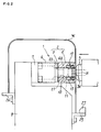
- Figure 1 shows apparatus for attaching self-piercing nuts in the horizontal direction to a metal panel, viz. a workpiece "W” that has been bent into a reversed-U shape.
- Figures 2 and 3 illustrate in sequential order the operation of the apparatus shown in Figure 1.
- an operative portion referred to as a punch block 2 comprises a striking punch 3 and a nut holder 4, and can be located inside the workpiece "W".
- a piercing-caulking die 5 is to be located outside the workpiece.
- the striking punch 3 is rigidly connected by a punch holder 6 to a back plate 7.
- This back plate 7, contacting and supporting the basal end of the punch 3, is fixed on a base 8 such that the punch 3 protruding sideways has its axis extending in a horizontal direction.
- the piercing-caulking die 5 disposed outside the workpiece "W" also extends horizontally to face the striking punch 3.
- the die 5 has its axis in alignment with that of the punch 3.
- a cam slide of a pressing machine not shown will drive the die 5 to reciprocate along its axis towards and away from the punch 3.
- the nut holder 4 has a guide passage 10 formed therein to receive and permit the striking punch 3 to slide fore and aft.
- the nut holder 4 further has a feed path 12 extending perpendicular to the guide passage 10.
- the feed path 12 formed through a chute portion 4a of the nut holder has a nut-feeding end aperture 11 opening into and communicating with the guide passage 10.
- a chute hose 14 is attached by a joint 13 to the rear end of the chute portion 4a, so that self-piercing nuts "N" supplied through the hose 14 can advance through the feed path 12 and the end aperture 11 into a delivery area.
- This area defined in the guide passage 10 is located near and in front of the distal (viz. frontal) free end 3a of the punch 3.
- a pair of fingers 15 are provided in the nut holder 4 so as temporarily to hold the nut "N" in place within the guide passage 10.
- the nut holder further has a sensor 16 to detect the nut "N" having entered the delivery area.
- the nut holder 4 Since the striking punch 3 is fixed to the base 8, the nut holder 4 has to reciprocate along, relative to and axially of the punch. In order to smooth such a reciprocation, a guide post 17 fixed on the nut holder 4 extends in parallel with the punch 3. This guide post is slidably inserted in a bearing sleeve 19, which is fitted in a bearing hole 18 formed in the punch holder 6 mentioned above.
- a pneumatic cylinder 20 having a base end secured to the back plate 7 is located adjacent to the punch holder 6.
- the cylinder 20 is the double-acting type has a piston rod 21 extending in parallel with the punch 3.
- a distal end of the piston rod 21 is connected to the chute portion 4a of the nut holder 4.
- the rod 21 and the holder 4 can move fore and aft in unison with each other, and long the punch 3.
- a nut "N" can transfer from the end aperture 11 to the delivery area formed in the guide passage 10.
- the nut holder 4 is at a retracted position shown by the phantom lines in figure 4, the frontal end 3a of the punch 3 will stand in flush with or slightly protrude out of an end opening of the passage 10.
- the nut holder 4 temporarily held at such a retracted position will close the nut-feeding end aperture 11 of the feed path 12, so that a succeeding nut "N" is prevented from undesirably entering the guide passage 10.
- the base 8 has brackets 25 and 26 secured to its front and rear sides, respectively to support the workpiece "W” to which the self-piercing nuts "N" have to be attached.
- a stopper 27 protruding from the front bracket 25 serves to hold the workpiece at its correct position.
- Figure 1 shows the described apparatus 1 in its state ready to strike and attach the nut to a panel.
- the nut holder 4 is urged by the pneumatic cylinder 20 to take its foremost position.
- the nut "N” is held in the delivery area within the guide passage 10.
- the front face of the nut holder 4 is in contact with the inner face of a vertical wall of the workpiece "W” held at its correct position.
- the piercing-caulking die 5 is at a retracted position.
- the die 5 will be driven towards the workpiece "W” so as to press the workpiece against the punch 3.
- the workpiece and the nut holder 4 will be moved in unison and rearwardly a small distance along the punch 3, against the resistance imparted by the pneumatic cylinder 20.
- the punch 3 will assume a thrust position relative to the nut holder, as if having moved forward a little.
- the self-piercing nut "N” is thrust strongly by the punch 3 towards the workpiece "W” as shown in Figure 2, so that the front face of the nut pierces a portion of the workpiece.
- the piercing-caulking die 5 will caulk the rim around the thus pierced hole so as to fix the nut on the workpiece.
- the pneumatic cylinder 20 will retract the nut holder 4 away from the nut "N" attached to the workpiece"W", as shown in Figure 3.
- the piercing-caulking die 5 is also retracted to liberate the workpiece, which will then be lifted and transferred to a subsequent work station.
- the nut "N” is struck horizontally to be attached to a vertical wall of workpiece "W” which is of a reversed-U shape.
- the apparatus provided herein may also be used to strike the nuts upward to be fixed to a lower side of any workpiece's top.
- the apparatus can be installed in a pressing machine of a small "shut height”.
- the striking punch is slidably inserted through the nut holder which in turn is driven fore and aft along the punch by the double-acting pneumatic cylinder. Therefore, the punch block consisting of the punch 3 and nut holder 4 in this apparatus can be of such a small dimension in the direction of their axes as to be installable in a pressing machine of small shut height. Self-piercing nuts can thus be attached to an inner side of a workpiece that may be of reversed-U or -L shape or hat-shape or the like. The nut holder at its retracted position closes the nut-feeding aperture so as reliably to inhibit succeeding nuts from entering the delivery area.
Landscapes
- Engineering & Computer Science (AREA)
- Mechanical Engineering (AREA)
- Automatic Assembly (AREA)
Description
- The invention relates to apparatus for attaching self-piercing nuts to one side of a panel such as a metal plate.
- In such apparatus each nut driven by a punch has an end face to cooperate with a piercing-caulking die located on the other side of the panel and in alignment with the nut, such that the end face is forced to bite the panel to form therein a hole, whose rim is simultaneously caulked so as to deform plastically and become integral with the nut.
- Self-piercing nuts capable of being secured to a metal plate when the plate is pressed have been used and are being used more and more in the mass production of metal plate products particularly in the automobile industry.
- Apparatuses for attaching the self-piercing nuts to a panel usually comprises a punch located on one side of the panel and striking the nuts towards the panel and also a piercing-caulking die facing the punch and located on the other side of the panel. Such an apparatus further comprises a guide member through which the punch slidably reciprocates, and a nut holder having a path extending perpendicular to the guide member and terminating as an end aperture so as to feed the nuts. In many cases, such apparatus is incorporated in a pressing machine together with other pressing dies or tools. The nuts are not necessarily fixed only to a plane portion of a metal panel, but often fixed to bottoms defining bent or drawn portions of L-shape or U-shape.
- Typically, the prior art apparatus for fixing the self-piercing nuts onto a metallic panel are constructed in such a manner as disclosed for example in the Japanese Utility Model Publication No. 63-20512. This apparatus comprises a nut holder capable of sliding along and relative to a punch for striking each nut. The nut holder has a guide post secured thereto and extending in parallel with the punch. A spring disposed in the guide post always urges the nut holder towards its normal position. The guide post is designed to be long enough to protect the nut from jamming while sliding along the punch. In consequence, a portion (hereinafter referred to as "punch block") consisting of the punch and the nut holder in the apparatus must be of such an increased overall height of length that the apparatus is difficult to be installed in a pressing machine having a small "shut height".
- The punch block may have to he placed in a hollow recess of the metal plate (hereinafter referred to as "work-piece") that has been pressed into a reversed-L, reversed-U or hat shape. Correspondingly, the piercing-caulking die is located outside the workpiece. However, it is difficult for the prior art punch block to take its operable position in such a narrow space, due to such a large axial dimension. Thus, it has scarcely been possible to secure the self-piercing nuts to an upright wall of the hollow space.
- Patent specification JP-A-06134628, upon the disclosure of which the first part of
claim 1 is based, discloses a pressing punch supported in a holder and operatively connected by a back plate to a ram. The punch is longitudinally aligned in series and operatively connected to a piston of a hydraulic cylinder. A nut holder as well as a caulking die are always kept still. Therefore, the punch has to reciprocate a greater distance, and such a linear series of the punch and cylinder/piston is rendered so lengthy axially thereof as disabling the device to work within a narrow space ( viz., within a relatively small "shut height" ). - According to the invention there is provided apparatus for attaching self-piercing nuts to a metal panel, the apparatus comprising:
- a punch to be located on one side of the panel and capable of striking nuts towards the panel, the punch being rigidly connected by a punch holder to a back plate;
- a piercing-caulking die facing the punch and to be located on the other side of the panel;
- a nut holder having a guide passage formed to allow the punch slidably to reciprocate therein, the nut holder having a feed path extending perpendicular to the guide passage and terminating as a nut-feeding end aperture; and
- a pair of fingers built in the nut holder so as temporarily to hold the nut in
place within the guide passage after the nut has passed through the end aperture into
a delivery area located near and ahead of a fronted end of the punch, wherein the
back plate is connected to and supports a rear end of the punch;
characterised in that a double-acting pneumatic cylinder is secured to the back plate and has a piston rod extending in parallel with the punch; and the nut holder is operatively connected to the piston rod so as to be driven fore and aft along the punch, so that the nuts are supplied through the end aperture into the delivery area when the nut holder is at its extended position;
wherein the frontal end of the punch is located flush with or slightly protrudes ahead of an end opening of the guide passage so that the feed path is closed by the punch when the nut holder is at its retracted position. -
- Preferably the apparatus further comprises a guide post fixed on the nut holder extending in parallel with the punch, wherein the guide post is slidably inserted in a bearing sleeve, which is fitted in a bearing hole formed in the punch holder.
- Advantageously the back plate rigidly connects the punch to a base, and the piercing-caulking die facing the punch is driven towards and away from the punch in response to movement of the pneumatic cylinder;
wherein the piercing-caulking die is capable of being driven towards the panel so as to press it against the punch, while moving the panel and the nut holder rearwardly in unison with each other a small distance so that the nut comes into contact with the panel, with the punch thrusting the nut onto the panel, whereby the nut and the die cooperate with each other to pierce a portion of the panel and simultaneously the die caulks a rim around a hole thus formed through the panel so as to secure the nut thereto, before the pneumatic cylinder retracts the nut holder away from the thus attached to the panel. - Preferably the punch and the die facing one another stand substantially horizontally and in alignment with each other.
- Such apparatus can have a punch block whose length or height in its axial direction is reduced to such an extent as to be installed in any pressing machine of a small shut height, thereby allowing the end face of each self-piercing nut to be secured to an inner vertical wall that defines a narrow space of a U- or the like shape formed in a metallic panel.
- In operation, the pneumatic cylinder will drive the nut holder forward and towards its extended position so that a leading one of the nuts can be supplied through the feed path and end aperture thereof and into the delivery area. Then, the punch and the piercing-caulking die will be driven towards each other until the die comes into contact with a desired portion of the panel, before striking the nut at its rear face with the punch so that the nut's front face bites and pierces the desired portion. Simultaneously with the punching of the panel to form a hole at that portion, the die will caulk the rim of the hole to deform and become integral with the self-piercing nut. Subsequently, the cylinder will pull the nut holder back to its retracted position away from the nut thus secured to the panel. The die will also be retracted at the same time so that the panel having the nut secured thereto is freed to undergo the next manufacturing process. The retracted nut holder keeps the end aperture closed by the punch so as not to feed the succeeding nut, until opened again to feed it when the nut holder advances forward again in the next cycle.
- The invention is diagrammatically illustrated by way of example in the accompanying drawings, in which:-
- Figure 1 is a front elevation of an apparatus for attaching a self-piercing nut to a panel according to the invention and shown partly in cross section;
- Figure 2 is also a front elevation of the apparatus of Figure 1 shown in a state in which one nut has just been struck to and pierced the panel;
- Figure 3 is a front elevation of the apparatus of Figure 1 in a state in which the nut has just been fixedly attached to the panel;
- Figure 4 is a vertical cross section of a punch block incorporated in the apparatus of Figure 1 and comprising a punch and a nut holder; and
- Figure 5 is a plan view of the punch block.
-
- Referring to the drawings, Figure 1 shows apparatus for attaching self-piercing nuts in the horizontal direction to a metal panel, viz. a workpiece "W" that has been bent into a reversed-U shape. Figures 2 and 3 illustrate in sequential order the operation of the apparatus shown in Figure 1. As seen in these figures, in
apparatus 1 an operative portion referred to as apunch block 2 comprises astriking punch 3 and anut holder 4, and can be located inside the workpiece "W". Correspondingly, a piercing-caulking die 5 is to be located outside the workpiece. - The
striking punch 3 is rigidly connected by apunch holder 6 to aback plate 7. Thisback plate 7, contacting and supporting the basal end of thepunch 3, is fixed on abase 8 such that thepunch 3 protruding sideways has its axis extending in a horizontal direction. - The piercing-
caulking die 5 disposed outside the workpiece "W" also extends horizontally to face thestriking punch 3. Thedie 5 has its axis in alignment with that of thepunch 3. A cam slide of a pressing machine not shown will drive thedie 5 to reciprocate along its axis towards and away from thepunch 3. - As is best seen in Figure 4, the
nut holder 4 has aguide passage 10 formed therein to receive and permit thestriking punch 3 to slide fore and aft. Thenut holder 4 further has a feed path 12 extending perpendicular to theguide passage 10. The feed path 12 formed through a chute portion 4a of the nut holder has a nut-feedingend aperture 11 opening into and communicating with theguide passage 10. Achute hose 14 is attached by a joint 13 to the rear end of the chute portion 4a, so that self-piercing nuts "N" supplied through thehose 14 can advance through the feed path 12 and theend aperture 11 into a delivery area. This area defined in theguide passage 10 is located near and in front of the distal (viz. frontal) free end 3a of thepunch 3. A pair offingers 15 are provided in thenut holder 4 so as temporarily to hold the nut "N" in place within theguide passage 10. The nut holder further has asensor 16 to detect the nut "N" having entered the delivery area. - Since the
striking punch 3 is fixed to thebase 8, thenut holder 4 has to reciprocate along, relative to and axially of the punch. In order to smooth such a reciprocation, aguide post 17 fixed on thenut holder 4 extends in parallel with thepunch 3. This guide post is slidably inserted in abearing sleeve 19, which is fitted in abearing hole 18 formed in thepunch holder 6 mentioned above. - A
pneumatic cylinder 20 having a base end secured to theback plate 7 is located adjacent to thepunch holder 6. Thecylinder 20 is the double-acting type has apiston rod 21 extending in parallel with thepunch 3. A distal end of thepiston rod 21 is connected to the chute portion 4a of thenut holder 4. Thus, therod 21 and theholder 4 can move fore and aft in unison with each other, and long thepunch 3. When thenut holder 4 is temporarily at its extended position shown by the solid lines in Figure 4, a nut "N" can transfer from theend aperture 11 to the delivery area formed in theguide passage 10. If, on the contrary, thenut holder 4 is at a retracted position shown by the phantom lines in figure 4, the frontal end 3a of thepunch 3 will stand in flush with or slightly protrude out of an end opening of thepassage 10. Thenut holder 4 temporarily held at such a retracted position will close the nut-feedingend aperture 11 of the feed path 12, so that a succeeding nut "N" is prevented from undesirably entering theguide passage 10. - The
base 8 hasbrackets stopper 27 protruding from thefront bracket 25 serves to hold the workpiece at its correct position. - Figure 1 shows the described
apparatus 1 in its state ready to strike and attach the nut to a panel. Thenut holder 4 is urged by thepneumatic cylinder 20 to take its foremost position. The nut "N" is held in the delivery area within theguide passage 10. The front face of thenut holder 4 is in contact with the inner face of a vertical wall of the workpiece "W" held at its correct position. The piercing-caulking die 5 is at a retracted position. Next, thedie 5 will be driven towards the workpiece "W" so as to press the workpiece against thepunch 3. In consequence, the workpiece and thenut holder 4 will be moved in unison and rearwardly a small distance along thepunch 3, against the resistance imparted by thepneumatic cylinder 20. Thus, thepunch 3 will assume a thrust position relative to the nut holder, as if having moved forward a little. As a result, the self-piercing nut "N" is thrust strongly by thepunch 3 towards the workpiece "W" as shown in Figure 2, so that the front face of the nut pierces a portion of the workpiece. At the same time, the piercing-caulking die 5 will caulk the rim around the thus pierced hole so as to fix the nut on the workpiece. Once the nut is struck and attached to the workpiece, thepneumatic cylinder 20 will retract thenut holder 4 away from the nut "N" attached to the workpiece"W", as shown in Figure 3. The piercing-caulking die 5 is also retracted to liberate the workpiece, which will then be lifted and transferred to a subsequent work station. - In the described embodiment, the nut "N" is struck horizontally to be attached to a vertical wall of workpiece "W" which is of a reversed-U shape. However, the apparatus provided herein may also be used to strike the nuts upward to be fixed to a lower side of any workpiece's top. The apparatus can be installed in a pressing machine of a small "shut height".
- In summary, the striking punch is slidably inserted through the nut holder which in turn is driven fore and aft along the punch by the double-acting pneumatic cylinder. Therefore, the punch block consisting of the
punch 3 andnut holder 4 in this apparatus can be of such a small dimension in the direction of their axes as to be installable in a pressing machine of small shut height. Self-piercing nuts can thus be attached to an inner side of a workpiece that may be of reversed-U or -L shape or hat-shape or the like. The nut holder at its retracted position closes the nut-feeding aperture so as reliably to inhibit succeeding nuts from entering the delivery area.
Claims (4)
- Apparatus for attaching self-piercing nuts to a metal panel (W), the apparatus (1) comprising:a punch (3) to be locate on one side of the panel (W) and capable of striking nuts (N) towards the panel (W), the punch (3) being rigidly connected by a punch holder (6) to a back plate (7);a piercing-caulking die (5) facing the punch (3) and to be located on the other side of the panel (W);a nut holder (4) having a guide passage (10) formed to allow the punch (3) slidably to reciprocate therein, the nut holder (4) having a feed path (12) extending perpendicular to the guide passage (10) and terminating as a nut-feeding end aperture (11); anda pair of fingers (15) built in the nut holder so as temporarily to hold the nut (N) in place within the guide passage (10) after the nut has passed through the end aperture (11) into a delivery area located near and ahead of a frontal end (3a) of the punch (3), wherein the back plate (7) is connected to and supports a rear end of the punch (3);
characterised in that a double-acting pneumatic cylinder (20) is secured to the back plate (7) and has a piston rod (21) extending in parallel with the punch (3), and the nut holder (4) is operatively connected to the piston rod (21) so as to be driven fore and aft along the punch (3), so that the nuts (N) are supplied through the end aperture (11) into the delivery area when the nut holder (4) is at its extended position;
wherein the frontal end (3a) of the punch (3) is located flush with or slightly protrudes ahead of an end opening of the guide passage (10) so that the feed path (12) is closed by the punch (3) when the nut holder (4) is at its retracted position. - Apparatus according to claim 1, further comprising a guide post (17) fixed on the nut holder (4) extending in parallel with the punch (3), wherein the guide post (17) is slidably inserted in a bearing sleeve (19), which is fitted in a bearing hole (18) formed in the punch holder (6).
- Apparatus according to claim 1 or claim 2, whereinthe back plate (7) rigidly connects the punch (3) to a base (8), and the piercing-caulking die (5) facing the punch (3) is driven towards and away from the punch (3) in response to movement of the pneumatic cylinder;
wherein the piercing-caulking die (5) is capable of being driven towards the panel (W) so as to press it against the punch (3), while moving the panel (W) and the nut holder (4) rearwardly in unison with each other a small distance so that the nut (N) comes into contact with the panel (W), with the punch (3) thrusting the nut (N) onto the panel (W), whereby the nut (N) and the die (5) cooperate with each other to pierce a portion of the panel (W) and simultaneously the die (5) caulks a rim around a hole thus formed through the panel (W) so as to secure the nut (N) thereto, before the pneumatic cylinder (20) retracts the nut holder (4) away from the nut (N) thus attached to the panel (W). - Apparatus according to claim 3, wherein the punch (3) and the die (5) facing one another stand substantially horizontally and in alignment with each other.
Applications Claiming Priority (3)
| Application Number | Priority Date | Filing Date | Title |
|---|---|---|---|
| JP24464094 | 1994-09-12 | ||
| JP6244640A JP2566538B2 (en) | 1994-09-12 | 1994-09-12 | Piercing nut driving device |
| JP244640/94 | 1994-09-12 |
Publications (2)
| Publication Number | Publication Date |
|---|---|
| EP0700750A1 EP0700750A1 (en) | 1996-03-13 |
| EP0700750B1 true EP0700750B1 (en) | 1999-11-24 |
Family
ID=17121763
Family Applications (1)
| Application Number | Title | Priority Date | Filing Date |
|---|---|---|---|
| EP95306109A Expired - Lifetime EP0700750B1 (en) | 1994-09-12 | 1995-09-01 | Apparatus for attaching self-piercing nuts to a panel |
Country Status (4)
| Country | Link |
|---|---|
| US (1) | US5657536A (en) |
| EP (1) | EP0700750B1 (en) |
| JP (1) | JP2566538B2 (en) |
| DE (1) | DE69513464T2 (en) |
Families Citing this family (7)
| Publication number | Priority date | Publication date | Assignee | Title |
|---|---|---|---|---|
| US6067696A (en) * | 1998-04-08 | 2000-05-30 | Dimitrios G. Cecil | Quality control system for a clinching station |
| US6148507A (en) * | 1999-03-12 | 2000-11-21 | Swanson; Jeffery S | Machine for pressing a fastener through sheet metal studs |
| EP1549455B1 (en) * | 2002-09-05 | 2018-08-08 | Strömsholmen AB | Tool for piercing nut |
| US6993831B2 (en) * | 2004-03-16 | 2006-02-07 | Whitesell International Corporation | Fastener installation apparatus |
| US8881364B2 (en) | 2010-12-03 | 2014-11-11 | Btm Corporation | Pierce nut insertion tool |
| CN110125665B (en) * | 2019-04-25 | 2021-08-24 | 惠州益伸电子有限公司 | Nut adapter |
| CN113941844B (en) * | 2020-07-15 | 2022-11-22 | 中国航发商用航空发动机有限责任公司 | Mounting and detecting tool |
Family Cites Families (16)
| Publication number | Priority date | Publication date | Assignee | Title |
|---|---|---|---|---|
| US3108368A (en) * | 1957-03-25 | 1963-10-29 | Multifastener Corp | Method of sizing and installing a pierce nut in a panel |
| US3718965A (en) * | 1971-06-03 | 1973-03-06 | Multifastener Corp | Pierce nut installation head |
| US4153989A (en) * | 1976-12-11 | 1979-05-15 | Yugenkaisha Shinjo Seisakusho | Automatic piercing nut assembling arrangement |
| US4164072A (en) * | 1976-12-11 | 1979-08-14 | Yugenkaisha Shinjo Seisakusho | Automatic piercing nut assembling arrangement |
| US4242793A (en) * | 1979-05-25 | 1981-01-06 | Multifastener Corporation | Nut guide for installation head |
| US4700470A (en) * | 1980-02-02 | 1987-10-20 | Multifastener Corporation | Fastener installation apparatus |
| US4348796A (en) * | 1980-02-06 | 1982-09-14 | Multifastener Corporation | Nut installation apparatus and method |
| JPS56119340A (en) * | 1980-02-26 | 1981-09-18 | Shinjiyou Seisakusho:Kk | Pierce nut automatic building-up device |
| US4384667A (en) * | 1981-04-29 | 1983-05-24 | Multifastener Corporation | Fastener installation tool and bolster assembly |
| IT1157145B (en) * | 1982-12-15 | 1987-02-11 | Filippo Volpe | PROCEDURE FOR FIXING A THREADED NUT TO A SEMI-FINISHED SHEET METAL AND NUT USED IN SUCH PROCEDURE |
| JPS62124838A (en) * | 1985-11-26 | 1987-06-06 | Shinjiyou Seisakusho:Kk | Temporary nut feed stopping device in automatic piercing nut assembly device |
| JPH0752372B2 (en) * | 1986-07-14 | 1995-06-05 | 株式会社ユニシアジェックス | Solenoid drive circuit |
| JPS6320512U (en) | 1986-07-25 | 1988-02-10 | ||
| US4785529A (en) * | 1987-06-16 | 1988-11-22 | Rb & W Corporation | Fastener mounting apparatus |
| JPH06134628A (en) * | 1992-07-22 | 1994-05-17 | Shinjiyou Seisakusho:Yugen | Automatic assembling device for pierce nut |
| JP2537135B2 (en) * | 1994-02-10 | 1996-09-25 | 有限会社新城製作所 | Piercing nut driving device |
-
1994
- 1994-09-12 JP JP6244640A patent/JP2566538B2/en not_active Expired - Lifetime
-
1995
- 1995-09-01 DE DE69513464T patent/DE69513464T2/en not_active Expired - Lifetime
- 1995-09-01 US US08/523,524 patent/US5657536A/en not_active Expired - Lifetime
- 1995-09-01 EP EP95306109A patent/EP0700750B1/en not_active Expired - Lifetime
Also Published As
| Publication number | Publication date |
|---|---|
| EP0700750A1 (en) | 1996-03-13 |
| JPH0885025A (en) | 1996-04-02 |
| US5657536A (en) | 1997-08-19 |
| DE69513464D1 (en) | 1999-12-30 |
| DE69513464T2 (en) | 2000-05-18 |
| JP2566538B2 (en) | 1996-12-25 |
Similar Documents
| Publication | Publication Date | Title |
|---|---|---|
| US7559136B2 (en) | Press for attaching nuts to pipes | |
| CA1208046A (en) | Riveting apparatus | |
| US10799938B2 (en) | Setting unit and method for setting a connecting unit on a workpiece | |
| US10654094B2 (en) | Device and method for setting a connecting element on a workpiece | |
| US3658230A (en) | Automatic blind riveting machines | |
| US5657536A (en) | Apparatus for attaching self-piercing nuts to a panel | |
| US3089360A (en) | Feed head | |
| US6568236B2 (en) | Rivet setting machine | |
| EP0388117A1 (en) | Method and apparatus for pull-through blind installation of a tubular member | |
| US20010011039A1 (en) | Nut punching apparatus | |
| EP0667208B1 (en) | Apparatus for automatically fixing self-piercing nuts | |
| DE102017109652A1 (en) | Device for joining a press-in element to a workpiece | |
| US3585832A (en) | Metal working | |
| US4966028A (en) | Multi-stage cold forging machine | |
| CN118417487A (en) | Pot body and handle riveter | |
| JPH0337452B2 (en) | ||
| JP2563268Y2 (en) | Tool | |
| US3892120A (en) | Riveting apparatus | |
| EP1250211B1 (en) | Press and delivery system for a press | |
| US3353254A (en) | Part feeding apparatus | |
| US5788140A (en) | Device for driving inserts into pieces of sheet metal | |
| DE917044C (en) | Method and device for perforating pre-forged workpieces, e.g. Nuts | |
| JPH10263951A (en) | Automatic nut tightening machine | |
| JPH0649396Y2 (en) | Forging abnormality detection device in forging machine | |
| JPS605954Y2 (en) | Header product discharge device |
Legal Events
| Date | Code | Title | Description |
|---|---|---|---|
| PUAI | Public reference made under article 153(3) epc to a published international application that has entered the european phase |
Free format text: ORIGINAL CODE: 0009012 |
|
| AK | Designated contracting states |
Kind code of ref document: A1 Designated state(s): DE FR GB IT |
|
| 17P | Request for examination filed |
Effective date: 19960712 |
|
| 17Q | First examination report despatched |
Effective date: 19980724 |
|
| GRAG | Despatch of communication of intention to grant |
Free format text: ORIGINAL CODE: EPIDOS AGRA |
|
| GRAG | Despatch of communication of intention to grant |
Free format text: ORIGINAL CODE: EPIDOS AGRA |
|
| GRAG | Despatch of communication of intention to grant |
Free format text: ORIGINAL CODE: EPIDOS AGRA |
|
| GRAH | Despatch of communication of intention to grant a patent |
Free format text: ORIGINAL CODE: EPIDOS IGRA |
|
| GRAH | Despatch of communication of intention to grant a patent |
Free format text: ORIGINAL CODE: EPIDOS IGRA |
|
| GRAA | (expected) grant |
Free format text: ORIGINAL CODE: 0009210 |
|
| AK | Designated contracting states |
Kind code of ref document: B1 Designated state(s): DE FR GB IT |
|
| REF | Corresponds to: |
Ref document number: 69513464 Country of ref document: DE Date of ref document: 19991230 |
|
| ET | Fr: translation filed | ||
| PLBE | No opposition filed within time limit |
Free format text: ORIGINAL CODE: 0009261 |
|
| STAA | Information on the status of an ep patent application or granted ep patent |
Free format text: STATUS: NO OPPOSITION FILED WITHIN TIME LIMIT |
|
| 26N | No opposition filed | ||
| REG | Reference to a national code |
Ref country code: GB Ref legal event code: IF02 |
|
| PGFP | Annual fee paid to national office [announced via postgrant information from national office to epo] |
Ref country code: DE Payment date: 20140827 Year of fee payment: 20 |
|
| PGFP | Annual fee paid to national office [announced via postgrant information from national office to epo] |
Ref country code: GB Payment date: 20140917 Year of fee payment: 20 |
|
| PGFP | Annual fee paid to national office [announced via postgrant information from national office to epo] |
Ref country code: IT Payment date: 20140911 Year of fee payment: 20 |
|
| PGFP | Annual fee paid to national office [announced via postgrant information from national office to epo] |
Ref country code: FR Payment date: 20140906 Year of fee payment: 20 |
|
| REG | Reference to a national code |
Ref country code: DE Ref legal event code: R071 Ref document number: 69513464 Country of ref document: DE |
|
| REG | Reference to a national code |
Ref country code: GB Ref legal event code: PE20 Expiry date: 20150831 |
|
| PG25 | Lapsed in a contracting state [announced via postgrant information from national office to epo] |
Ref country code: GB Free format text: LAPSE BECAUSE OF EXPIRATION OF PROTECTION Effective date: 20150831 |