EP0700503B1 - Pin oven system for cans - Google Patents
Pin oven system for cans Download PDFInfo
- Publication number
- EP0700503B1 EP0700503B1 EP94918173A EP94918173A EP0700503B1 EP 0700503 B1 EP0700503 B1 EP 0700503B1 EP 94918173 A EP94918173 A EP 94918173A EP 94918173 A EP94918173 A EP 94918173A EP 0700503 B1 EP0700503 B1 EP 0700503B1
- Authority
- EP
- European Patent Office
- Prior art keywords
- cans
- duct
- walls
- end wall
- generally
- Prior art date
- Legal status (The legal status is an assumption and is not a legal conclusion. Google has not performed a legal analysis and makes no representation as to the accuracy of the status listed.)
- Expired - Lifetime
Links
- 238000001035 drying Methods 0.000 claims description 28
- 238000003491 array Methods 0.000 claims description 6
- WYTGDNHDOZPMIW-RCBQFDQVSA-N alstonine Natural products C1=CC2=C3C=CC=CC3=NC2=C2N1C[C@H]1[C@H](C)OC=C(C(=O)OC)[C@H]1C2 WYTGDNHDOZPMIW-RCBQFDQVSA-N 0.000 claims description 4
- 238000000576 coating method Methods 0.000 description 6
- 238000004519 manufacturing process Methods 0.000 description 4
- VNWKTOKETHGBQD-UHFFFAOYSA-N methane Chemical compound C VNWKTOKETHGBQD-UHFFFAOYSA-N 0.000 description 4
- 235000013361 beverage Nutrition 0.000 description 3
- 239000011248 coating agent Substances 0.000 description 3
- 239000000976 ink Substances 0.000 description 3
- 238000000034 method Methods 0.000 description 3
- 238000010276 construction Methods 0.000 description 2
- 239000007789 gas Substances 0.000 description 2
- 238000010438 heat treatment Methods 0.000 description 2
- 239000003345 natural gas Substances 0.000 description 2
- 238000011144 upstream manufacturing Methods 0.000 description 2
- UGFAIRIUMAVXCW-UHFFFAOYSA-N Carbon monoxide Chemical compound [O+]#[C-] UGFAIRIUMAVXCW-UHFFFAOYSA-N 0.000 description 1
- 229910000831 Steel Inorganic materials 0.000 description 1
- 230000001133 acceleration Effects 0.000 description 1
- XAGFODPZIPBFFR-UHFFFAOYSA-N aluminium Chemical compound [Al] XAGFODPZIPBFFR-UHFFFAOYSA-N 0.000 description 1
- 229910052782 aluminium Inorganic materials 0.000 description 1
- 239000004411 aluminium Substances 0.000 description 1
- 229910002091 carbon monoxide Inorganic materials 0.000 description 1
- 238000001816 cooling Methods 0.000 description 1
- 230000008878 coupling Effects 0.000 description 1
- 238000010168 coupling process Methods 0.000 description 1
- 238000005859 coupling reaction Methods 0.000 description 1
- 210000003298 dental enamel Anatomy 0.000 description 1
- 238000001599 direct drying Methods 0.000 description 1
- 230000000694 effects Effects 0.000 description 1
- 229920001971 elastomer Polymers 0.000 description 1
- 239000000806 elastomer Substances 0.000 description 1
- 230000005611 electricity Effects 0.000 description 1
- 230000008030 elimination Effects 0.000 description 1
- 238000003379 elimination reaction Methods 0.000 description 1
- 238000005265 energy consumption Methods 0.000 description 1
- 239000000446 fuel Substances 0.000 description 1
- 231100001261 hazardous Toxicity 0.000 description 1
- 239000004922 lacquer Substances 0.000 description 1
- 238000012423 maintenance Methods 0.000 description 1
- 230000003134 recirculating effect Effects 0.000 description 1
- 238000006748 scratching Methods 0.000 description 1
- 230000002393 scratching effect Effects 0.000 description 1
- 239000010959 steel Substances 0.000 description 1
- 230000007704 transition Effects 0.000 description 1
- 239000002966 varnish Substances 0.000 description 1
Images
Classifications
-
- F—MECHANICAL ENGINEERING; LIGHTING; HEATING; WEAPONS; BLASTING
- F26—DRYING
- F26B—DRYING SOLID MATERIALS OR OBJECTS BY REMOVING LIQUID THEREFROM
- F26B15/00—Machines or apparatus for drying objects with progressive movement; Machines or apparatus with progressive movement for drying batches of material in compact form
- F26B15/10—Machines or apparatus for drying objects with progressive movement; Machines or apparatus with progressive movement for drying batches of material in compact form with movement in a path composed of one or more straight lines, e.g. compound, the movement being in alternate horizontal and vertical directions
- F26B15/12—Machines or apparatus for drying objects with progressive movement; Machines or apparatus with progressive movement for drying batches of material in compact form with movement in a path composed of one or more straight lines, e.g. compound, the movement being in alternate horizontal and vertical directions the lines being all horizontal or slightly inclined
- F26B15/122—Machines or apparatus for drying objects with progressive movement; Machines or apparatus with progressive movement for drying batches of material in compact form with movement in a path composed of one or more straight lines, e.g. compound, the movement being in alternate horizontal and vertical directions the lines being all horizontal or slightly inclined the objects or batches of material being carried by transversely moving rollers or rods which may rotate
- F26B15/128—Machines or apparatus for drying objects with progressive movement; Machines or apparatus with progressive movement for drying batches of material in compact form with movement in a path composed of one or more straight lines, e.g. compound, the movement being in alternate horizontal and vertical directions the lines being all horizontal or slightly inclined the objects or batches of material being carried by transversely moving rollers or rods which may rotate the rods being attached at one end to an endless conveying means, the other end being free to receive hollow articles, e.g. cans
-
- F—MECHANICAL ENGINEERING; LIGHTING; HEATING; WEAPONS; BLASTING
- F26—DRYING
- F26B—DRYING SOLID MATERIALS OR OBJECTS BY REMOVING LIQUID THEREFROM
- F26B15/00—Machines or apparatus for drying objects with progressive movement; Machines or apparatus with progressive movement for drying batches of material in compact form
- F26B15/10—Machines or apparatus for drying objects with progressive movement; Machines or apparatus with progressive movement for drying batches of material in compact form with movement in a path composed of one or more straight lines, e.g. compound, the movement being in alternate horizontal and vertical directions
- F26B15/20—Machines or apparatus for drying objects with progressive movement; Machines or apparatus with progressive movement for drying batches of material in compact form with movement in a path composed of one or more straight lines, e.g. compound, the movement being in alternate horizontal and vertical directions the lines being all vertical or steeply inclined
- F26B15/22—Machines or apparatus for drying objects with progressive movement; Machines or apparatus with progressive movement for drying batches of material in compact form with movement in a path composed of one or more straight lines, e.g. compound, the movement being in alternate horizontal and vertical directions the lines being all vertical or steeply inclined the objects or batches of materials being carried by endless belts the objects or batches of material being carried by trays or holders supported by endless belts or chains
- F26B15/24—Machines or apparatus for drying objects with progressive movement; Machines or apparatus with progressive movement for drying batches of material in compact form with movement in a path composed of one or more straight lines, e.g. compound, the movement being in alternate horizontal and vertical directions the lines being all vertical or steeply inclined the objects or batches of materials being carried by endless belts the objects or batches of material being carried by trays or holders supported by endless belts or chains in a zig-zag path
Definitions
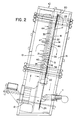
- the pin oven is enclosed is a generally rectangular housing 10 which, in the end view of FIG. 2, is shown tilted rearwardly slightly to help maintain the cans on the pins in a manner well known in the art.
- Heated air is supplied to the interior of the housing 10 by a gas heater 11 and is circulated within the housing by a recirculating fan 12.
- the interior of the housing 10 is divided into a supply chamber 13 for the heated drying air, a drying chamber 14 through which the cans are circulated, and a return chamber 15 into which the drying air is directed to be returned and reheated by the heater 11 for recirculation.
- the conveyor chain 17 may comprise a conventional roller chain, such as a No. 60 chain having a nominal 3/4 inch (19 mm) chain pitch.
- Long extended can carrier pins 21 are attached to the conveyor chain 17 at equally spaced intervals along the length thereof in any of several well known manners.
- the carrier pins 21 may comprise unitary extended chain connecting pins or they may be attached to more conventional chain connecting pins with a suitable coupling.
- the carrier pin spacing may conveniently be 133 mm (51 ⁇ 4 inches) which, on a 19 mm (3 ⁇ 4 inch) Pitch No. 66 roller chain, would locate a carrier pin 21 at each seventh connecting pin. In any event, the carrier pin spacing must be large enough to avoid any contact by adjacent cans 16 carried on the pins.
- the U-shaped duct 30 through which the cans are conveyed includes an end wall 35 and a pair of opposed side walls 36.
- the side walls 36 are parallel to one another and extend generally perpendicular to the end wall 35 such that the U-shaped duct is preferably rectangular. Heated pressurized air is directed from the supply chamber 13 into the duct 30 through special patterns of orifices in the end wall 35 and side walls 36.
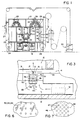
- the orifice pattern in each of the turn section end walls 38 comprises an array 29 of equally spaced perforations 39.
- the perforations are preferably provided in staggered rows in which the perforations are spaced 3.8 cm (11 ⁇ 2 inches) apart and adjacent rows spaced by half that distance or 1.9 cm (3 ⁇ 4 inch). This pattern results in mutually perpendicular diagonally extending rows of perforations all of which are equally spaced by approximately 2.5 cm (1 inch), as shown in Fig. 7.
- the perforations may be 9.5 mm (3/8 inch) in diameter.
- the width of each array 29 of perforations 39 extending around the turn section end wall 38 may be approximately 7.6 cm (3 inches).
- the supply chamber 13 is provided with pressure equalization chambers between the main portion of the supply chamber and the walls of the duct 30.
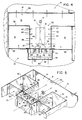
- an end wall pressure equalization chamber 48 extends along and encloses the rear face of the end wall 35 along its full length including the straight run portions 37 and the turn sections 38.
- the rear wall 50 of the pressure equalization chamber 48 is perforated over its entire extent to provide a relatively small open area relative to its total area, as shown in FIG. 6. In the present embodiment, the rear wall 50 is about 13% open.
- a side wall pressure equalization chamber 51 is provided on the back side of each side wall 36 of the duct 30.
- each pressure equalization chamber 51 is also provided with a pattern of perforations providing approximately 13% open area.
- the perforated rear walls 50 and 52 of the pressure equalization chambers 48 and 51, respectively, allow the somewhat turbulent flow of heated air in the supply chamber 13 to be modulated and distributed more evenly along the rear faces of the end wall 35 and side walls 36 and thereby provide more evenly distributed air flows through the slots and perforations against the cans 16 traveling in the duct 30.
- the end wall pressure equalization chamber 48 is preferably provided with a series of baffle plates 53 spaced along the interior of the chamber to further assist in the equalization of pressure within the chamber 48 and to further enhance the uniformity of flow through the slots 40 and 41. As may best be seen in FIG.
Landscapes
- Engineering & Computer Science (AREA)
- Mechanical Engineering (AREA)
- General Engineering & Computer Science (AREA)
- Drying Of Solid Materials (AREA)
Description
Claims (11)
- A can drying system for open-ended cylindrical cans mounted on generally horizontal elongate carrier pins (21) attached to a conveyor chain (17) in spaced relation therealong for movement in a serpentine chain path defined by a series of straight runs (18) connected by generally curved turn sections (20), the path disposed in a generally vertical plane, and including means (28) for driving said conveyor chain (17) and for carrying the cans (16) through the serpentine path, a duct (30) for each straight run (18) positioned parallel to and spaced from the conveyor chain (17) forming the run, said duct having an end wall (35) and a pair of opposing side walls (36), the end wall (35) being positioned generally parallel to and spaced from the closed bottom walls (33) of the cans (16), the end wall (35) and side walls (36) of said duct (30) each having a pattern of orifices (40, 41, 47) extending uniformly along the length of the duct, the orifices (40) provided in the end wall (35) directing pressurized heated air through the end wall (35) in a generally perpendicular direction against the bottom walls (33) of the cans (16), and characterized in that the duct is of open-faced generally U-shaped form, the carrier pins (21) and cans (16) mounted thereon extending into the duct (30), the side walls (36) extending generally perpendicularly from the end wall (35), the side walls (36) being positioned generally parallel to and spaced from the cylindrical walls (34) of the cans (16), wherein the orifices (47) provided in the side walls (36) direct pressurized heated air through the side walls (36) in a generally perpendicular direction against the cylindrical walls (34) of the cans (16).
- A system as claimed in Claim 1, characterized in that the end wall (35) orifice pattern comprises a series of parallel slots (40, 41) extending along the length of the duct (30).
- A system as claimed in Claim 2, characterized in that said series of slots comprises:a center slot (40) aligned with the straight run of the chain (17) to direct a flow of heated air directly against the bottom walls (33) of the cans (16); and,a side slot (41) positioned on each side of the center slot (40) to direct converging flows of heated air against the corners of the cans defined by the junctures of the can bottoms (33) and cylindrical walls (34).
- A system as claimed in Claim 1, characterized in that the orifice patterns in the side walls (36) are identical and comprise an array (46) of equally spaced perforations (47), said array positioned directly adjacent the cylindrical can walls (34) and having a width approximately equal to the height of the cans (16).
- A system as claimed in Claim 1, characterized by:a U-shaped curved duct section (30) for each curved turn section (20), each of said duct sections interconnecting the ends of an adjacent pair of straight run ducts (30);each duct section having a curved end wall (38) and a pair of concentric opposed curved side walls (45); and,the curved end wall (38) and curved side walls (45) of said duct sections having patterns (29, 46) of orifices (39, 47) extending uniformly along the duct section length contiguous with the orifice patterns for the interconnected straight run ducts.
- A system as claimed in Claim 5, characterized in that the orifice patterns for said straight run ducts and said curved duct sections comprise:a first array (29) of equally spaced perforations (39, 40, 41) extending along the full lengths of said end walls (37, 38); and,a second array (46) of equally spaced perforations (47) extending along the full length of said side walls (44, 45).
- A system as claimed in Claim 6, characterized in that:said first arrays (29) of perforations (39, 40, 41) are aligned generally with the path of movement of the chain (17) and have widths approximately equal to the diameter of the cans (16); and,said second arrays (46) of perforations (47) are positioned directly adjacent the cylindrical can walls (34) and have widths approximately equal to the height of the cans.
- A system as claimed in Claim 3, characterized in that said center slot (40) is wider than either of said side slots (41).
- A system as claimed in Claim 8, characterized in that said center slot (40) is greater than twice the width of either of said side slots (41).
- A system as claimed in Claim 1, characterized by:
a series of sprockets (22) supporting the chain for movement around each turn section, said sprockets spaced circumferentially along the generally semicircular curve of the turn section such that the chain (17) between each adjacent pair of said sprockets (22) lies generally on a chord of the curve, each sprocket having a diameter less than half the diameter of the curve. - A system as claimed in Claim 10, characterized in that said series of sprockets (22) comprises five identical sprockets having diameters approximately equal to one-fourth the diameter of the curve.
Applications Claiming Priority (3)
| Application Number | Priority Date | Filing Date | Title |
|---|---|---|---|
| US72604 | 1993-06-04 | ||
| US08/072,604 US5353520A (en) | 1993-06-04 | 1993-06-04 | Pin oven system for cans |
| PCT/US1994/006097 WO1994029657A1 (en) | 1993-06-04 | 1994-05-31 | Pin oven system for cans |
Publications (2)
| Publication Number | Publication Date |
|---|---|
| EP0700503A1 EP0700503A1 (en) | 1996-03-13 |
| EP0700503B1 true EP0700503B1 (en) | 1998-07-22 |
Family
ID=22108686
Family Applications (1)
| Application Number | Title | Priority Date | Filing Date |
|---|---|---|---|
| EP94918173A Expired - Lifetime EP0700503B1 (en) | 1993-06-04 | 1994-05-31 | Pin oven system for cans |
Country Status (6)
| Country | Link |
|---|---|
| US (1) | US5353520A (en) |
| EP (1) | EP0700503B1 (en) |
| JP (1) | JPH08511337A (en) |
| AU (1) | AU6961194A (en) |
| DE (1) | DE69411912D1 (en) |
| WO (1) | WO1994029657A1 (en) |
Families Citing this family (15)
| Publication number | Priority date | Publication date | Assignee | Title |
|---|---|---|---|---|
| DE19602784C2 (en) * | 1996-01-26 | 1998-04-09 | Ltg Lufttechnische Gmbh | Drying oven |
| HUE034446T2 (en) * | 2004-03-02 | 2018-02-28 | Procter & Gamble | A method for curing high internal phase emulsions |
| WO2005085338A1 (en) * | 2004-03-02 | 2005-09-15 | The Procter & Gamble Company | Preparation of foam materials from high internal phase emulsions |
| JP2006056629A (en) * | 2004-08-18 | 2006-03-02 | Daido Kogyo Co Ltd | Resin pin chip for pin chain and manufacturing method thereof |
| US8959793B2 (en) | 2013-03-14 | 2015-02-24 | International Thermal Systems, Inc. | Pin oven with a continuous U-shaped duct |
| DE102016119864A1 (en) * | 2016-10-18 | 2018-04-19 | Ulf Reinhardt | pin oven |
| DE102016119870A1 (en) * | 2016-10-18 | 2018-04-19 | Ulf Reinhardt | pin oven |
| US11920863B2 (en) | 2018-05-01 | 2024-03-05 | Universal Can Corporation | Nozzle, drying device, and method for producing can body |
| US10921059B2 (en) * | 2018-10-04 | 2021-02-16 | Illinois Tool Works Inc. | Method and apparatus for a dryer system |
| US12103039B2 (en) | 2020-05-26 | 2024-10-01 | Ball Corporation | Apparatus and method to heat metallic containers or workpieces |
| DE102021115612A1 (en) * | 2021-06-16 | 2022-12-22 | Ulf Reinhardt | Pin oven for drying container units and method |
| DE102021121346A1 (en) | 2021-08-17 | 2023-02-23 | Ulf Reinhardt | Drying device and method for drying containers containing cleaning fluid |
| DE102022113979A1 (en) | 2022-06-02 | 2023-12-07 | Krones Aktiengesellschaft | Device for drying containers |
| DE102022123370A1 (en) * | 2022-09-13 | 2024-03-14 | Belvac Production Machinery, Inc. | Drying system and method for drying a can coating of cans |
| CN117948786B (en) * | 2024-03-27 | 2024-07-16 | 宁德思客琦智能装备有限公司 | Baking and drying production line for battery cells |
Family Cites Families (6)
| Publication number | Priority date | Publication date | Assignee | Title |
|---|---|---|---|---|
| US3381391A (en) * | 1966-11-16 | 1968-05-07 | Midland Ross Corp | Apparatus for the drying or cooling of hollow containers while in transport |
| US4052152A (en) * | 1976-02-18 | 1977-10-04 | Sun Chemical Corporation | Direct flame drying apparatus |
| US4053993A (en) * | 1976-05-24 | 1977-10-18 | Midland-Ross Corporation | Oven for a procession of containers |
| GB2144988A (en) * | 1983-08-20 | 1985-03-20 | Metal Box Plc | Thermal treatment apparatus |
| US4662085A (en) * | 1984-11-29 | 1987-05-05 | Feco Engineered Systems, Inc. | Pin oven louver design |
| US5272970A (en) * | 1990-12-19 | 1993-12-28 | Carnaudmetalbox Plc | Pin ovens and transfer devices therefor |
-
1993
- 1993-06-04 US US08/072,604 patent/US5353520A/en not_active Expired - Lifetime
-
1994
- 1994-05-31 AU AU69611/94A patent/AU6961194A/en not_active Abandoned
- 1994-05-31 DE DE69411912T patent/DE69411912D1/en not_active Expired - Lifetime
- 1994-05-31 EP EP94918173A patent/EP0700503B1/en not_active Expired - Lifetime
- 1994-05-31 JP JP7501886A patent/JPH08511337A/en not_active Ceased
- 1994-05-31 WO PCT/US1994/006097 patent/WO1994029657A1/en not_active Ceased
Also Published As
| Publication number | Publication date |
|---|---|
| AU6961194A (en) | 1995-01-03 |
| JPH08511337A (en) | 1996-11-26 |
| WO1994029657A1 (en) | 1994-12-22 |
| DE69411912D1 (en) | 1998-08-27 |
| US5353520A (en) | 1994-10-11 |
| EP0700503A1 (en) | 1996-03-13 |
Similar Documents
| Publication | Publication Date | Title |
|---|---|---|
| US5353520A (en) | Pin oven system for cans | |
| US8959793B2 (en) | Pin oven with a continuous U-shaped duct | |
| CA1199543A (en) | High efficiency impingement heating and cooling apparatus | |
| US4474498A (en) | Multiple-pass impingement heating and cooling device | |
| US4873107A (en) | Air impingement tunnel oven apparatus | |
| US20020004994A1 (en) | Coating dryer system | |
| EP0816786B1 (en) | A method for drying a moving coated web avoiding mottle in the solvent coating | |
| CA2224348A1 (en) | Air impingement oven | |
| US4662085A (en) | Pin oven louver design | |
| JPH04292780A (en) | Pin heating furnace and its transfer device and method | |
| US5421316A (en) | Conveyor oven with improved air flow | |
| US3755916A (en) | Plenum discharge face employing honeycomb layer | |
| US5396716A (en) | Jet tube dryer with independently controllable modules | |
| WO1985005545A1 (en) | Continuous feed oven | |
| US3381391A (en) | Apparatus for the drying or cooling of hollow containers while in transport | |
| KR100847758B1 (en) | Blowing unit associated with the device for blowing fluid onto at least one side of the thin element | |
| CA1299866C (en) | Web treatment system | |
| JPH0310870B2 (en) | ||
| US20090181181A1 (en) | Method and device for powder coating wood substrates | |
| GB1570448A (en) | Conveying device | |
| US4165966A (en) | Direct flame drying apparatus (RM-30C) | |
| US3453743A (en) | Veneer dryer | |
| GB1570506A (en) | Conveyance of articles | |
| CN86104964A (en) | Louver Partition Wall Design of Rod Oven | |
| JPS5912541Y2 (en) | heat treatment equipment |
Legal Events
| Date | Code | Title | Description |
|---|---|---|---|
| PUAI | Public reference made under article 153(3) epc to a published international application that has entered the european phase |
Free format text: ORIGINAL CODE: 0009012 |
|
| 17P | Request for examination filed |
Effective date: 19951110 |
|
| AK | Designated contracting states |
Kind code of ref document: A1 Designated state(s): BE DE ES FR GB GR IT |
|
| 17Q | First examination report despatched |
Effective date: 19960515 |
|
| GRAG | Despatch of communication of intention to grant |
Free format text: ORIGINAL CODE: EPIDOS AGRA |
|
| GRAG | Despatch of communication of intention to grant |
Free format text: ORIGINAL CODE: EPIDOS AGRA |
|
| GRAH | Despatch of communication of intention to grant a patent |
Free format text: ORIGINAL CODE: EPIDOS IGRA |
|
| GRAH | Despatch of communication of intention to grant a patent |
Free format text: ORIGINAL CODE: EPIDOS IGRA |
|
| GRAA | (expected) grant |
Free format text: ORIGINAL CODE: 0009210 |
|
| AK | Designated contracting states |
Kind code of ref document: B1 Designated state(s): BE DE ES FR GB GR IT |
|
| PG25 | Lapsed in a contracting state [announced via postgrant information from national office to epo] |
Ref country code: IT Free format text: LAPSE BECAUSE OF FAILURE TO SUBMIT A TRANSLATION OF THE DESCRIPTION OR TO PAY THE FEE WITHIN THE PRE;WARNING: LAPSES OF ITALIAN PATENTS WITH EFFECTIVE DATE BEFORE 2007 MAY HAVE OCCURRED AT ANY TIME BEFORE 2007. THE CORRECT EFFECTIVE DATE MAY BE DIFFERENT FROM THE ONE RECORDED.SCRIBED TIME-LIMIT Effective date: 19980722 Ref country code: GR Free format text: LAPSE BECAUSE OF NON-PAYMENT OF DUE FEES Effective date: 19980722 Ref country code: ES Free format text: THE PATENT HAS BEEN ANNULLED BY A DECISION OF A NATIONAL AUTHORITY Effective date: 19980722 Ref country code: BE Free format text: LAPSE BECAUSE OF FAILURE TO SUBMIT A TRANSLATION OF THE DESCRIPTION OR TO PAY THE FEE WITHIN THE PRESCRIBED TIME-LIMIT Effective date: 19980722 |
|
| REF | Corresponds to: |
Ref document number: 69411912 Country of ref document: DE Date of ref document: 19980827 |
|
| PG25 | Lapsed in a contracting state [announced via postgrant information from national office to epo] |
Ref country code: DE Free format text: LAPSE BECAUSE OF FAILURE TO SUBMIT A TRANSLATION OF THE DESCRIPTION OR TO PAY THE FEE WITHIN THE PRESCRIBED TIME-LIMIT Effective date: 19981023 |
|
| ET | Fr: translation filed | ||
| PLBE | No opposition filed within time limit |
Free format text: ORIGINAL CODE: 0009261 |
|
| STAA | Information on the status of an ep patent application or granted ep patent |
Free format text: STATUS: NO OPPOSITION FILED WITHIN TIME LIMIT |
|
| 26N | No opposition filed | ||
| REG | Reference to a national code |
Ref country code: GB Ref legal event code: IF02 |
|
| PGFP | Annual fee paid to national office [announced via postgrant information from national office to epo] |
Ref country code: GB Payment date: 20130528 Year of fee payment: 20 |
|
| PGFP | Annual fee paid to national office [announced via postgrant information from national office to epo] |
Ref country code: FR Payment date: 20130606 Year of fee payment: 20 |
|
| REG | Reference to a national code |
Ref country code: GB Ref legal event code: PE20 Expiry date: 20140530 |
|
| PG25 | Lapsed in a contracting state [announced via postgrant information from national office to epo] |
Ref country code: GB Free format text: LAPSE BECAUSE OF EXPIRATION OF PROTECTION Effective date: 20140530 |