EP0698829B1 - Electrostatographic imaging member assembly - Google Patents
Electrostatographic imaging member assembly Download PDFInfo
- Publication number
- EP0698829B1 EP0698829B1 EP95305838A EP95305838A EP0698829B1 EP 0698829 B1 EP0698829 B1 EP 0698829B1 EP 95305838 A EP95305838 A EP 95305838A EP 95305838 A EP95305838 A EP 95305838A EP 0698829 B1 EP0698829 B1 EP 0698829B1
- Authority
- EP
- European Patent Office
- Prior art keywords
- imaging
- layer
- acoustic dampening
- substrate
- imaging member
- Prior art date
- Legal status (The legal status is an assumption and is not a legal conclusion. Google has not performed a legal analysis and makes no representation as to the accuracy of the status listed.)
- Expired - Lifetime
Links
- 238000003384 imaging method Methods 0.000 title claims description 106
- 239000000758 substrate Substances 0.000 claims description 30
- 239000006260 foam Substances 0.000 claims description 10
- 239000011111 cardboard Substances 0.000 claims description 3
- 239000007799 cork Substances 0.000 claims description 3
- 239000000123 paper Substances 0.000 claims description 3
- 239000004753 textile Substances 0.000 claims description 3
- 239000010410 layer Substances 0.000 description 60
- 239000000463 material Substances 0.000 description 29
- 238000004140 cleaning Methods 0.000 description 27
- 239000007789 gas Substances 0.000 description 22
- 230000000903 blocking effect Effects 0.000 description 7
- 239000012790 adhesive layer Substances 0.000 description 5
- 238000009434 installation Methods 0.000 description 5
- PXHVJJICTQNCMI-UHFFFAOYSA-N Nickel Chemical compound [Ni] PXHVJJICTQNCMI-UHFFFAOYSA-N 0.000 description 4
- 239000011230 binding agent Substances 0.000 description 4
- 230000000694 effects Effects 0.000 description 4
- 238000000034 method Methods 0.000 description 4
- 239000002245 particle Substances 0.000 description 4
- 108091008695 photoreceptors Proteins 0.000 description 4
- 239000011148 porous material Substances 0.000 description 4
- 206010039740 Screaming Diseases 0.000 description 3
- 239000000853 adhesive Substances 0.000 description 3
- 230000001070 adhesive effect Effects 0.000 description 3
- 229910052782 aluminium Inorganic materials 0.000 description 3
- XAGFODPZIPBFFR-UHFFFAOYSA-N aluminium Chemical compound [Al] XAGFODPZIPBFFR-UHFFFAOYSA-N 0.000 description 3
- 230000006835 compression Effects 0.000 description 3
- 238000007906 compression Methods 0.000 description 3
- 230000003993 interaction Effects 0.000 description 3
- 229910052751 metal Inorganic materials 0.000 description 3
- 239000002184 metal Substances 0.000 description 3
- XKRFYHLGVUSROY-UHFFFAOYSA-N Argon Chemical compound [Ar] XKRFYHLGVUSROY-UHFFFAOYSA-N 0.000 description 2
- IJGRMHOSHXDMSA-UHFFFAOYSA-N Atomic nitrogen Chemical compound N#N IJGRMHOSHXDMSA-UHFFFAOYSA-N 0.000 description 2
- CURLTUGMZLYLDI-UHFFFAOYSA-N Carbon dioxide Chemical compound O=C=O CURLTUGMZLYLDI-UHFFFAOYSA-N 0.000 description 2
- 244000007853 Sarothamnus scoparius Species 0.000 description 2
- 230000003213 activating effect Effects 0.000 description 2
- 239000004020 conductor Substances 0.000 description 2
- 238000010276 construction Methods 0.000 description 2
- 229920001971 elastomer Polymers 0.000 description 2
- 239000007788 liquid Substances 0.000 description 2
- 239000000203 mixture Substances 0.000 description 2
- 229910052759 nickel Inorganic materials 0.000 description 2
- 229920000620 organic polymer Polymers 0.000 description 2
- 239000004033 plastic Substances 0.000 description 2
- 229920003023 plastic Polymers 0.000 description 2
- 239000002984 plastic foam Substances 0.000 description 2
- 238000004064 recycling Methods 0.000 description 2
- 239000005060 rubber Substances 0.000 description 2
- 239000007787 solid Substances 0.000 description 2
- 238000011144 upstream manufacturing Methods 0.000 description 2
- 206010067482 No adverse event Diseases 0.000 description 1
- 239000004952 Polyamide Substances 0.000 description 1
- 239000004698 Polyethylene Substances 0.000 description 1
- 229920005830 Polyurethane Foam Polymers 0.000 description 1
- 238000005299 abrasion Methods 0.000 description 1
- 230000001133 acceleration Effects 0.000 description 1
- 239000003570 air Substances 0.000 description 1
- 239000004411 aluminium Substances 0.000 description 1
- 238000013459 approach Methods 0.000 description 1
- 229910052786 argon Inorganic materials 0.000 description 1
- 239000001569 carbon dioxide Substances 0.000 description 1
- 229910002092 carbon dioxide Inorganic materials 0.000 description 1
- 239000012876 carrier material Substances 0.000 description 1
- 239000011248 coating agent Substances 0.000 description 1
- 238000000576 coating method Methods 0.000 description 1
- 150000001875 compounds Chemical class 0.000 description 1
- 230000001351 cycling effect Effects 0.000 description 1
- 238000013016 damping Methods 0.000 description 1
- 238000005323 electroforming Methods 0.000 description 1
- 230000008030 elimination Effects 0.000 description 1
- 238000003379 elimination reaction Methods 0.000 description 1
- 239000004794 expanded polystyrene Substances 0.000 description 1
- 239000006261 foam material Substances 0.000 description 1
- 239000011521 glass Substances 0.000 description 1
- 238000005286 illumination Methods 0.000 description 1
- 238000002347 injection Methods 0.000 description 1
- 239000007924 injection Substances 0.000 description 1
- 229920000592 inorganic polymer Polymers 0.000 description 1
- 238000003780 insertion Methods 0.000 description 1
- 230000037431 insertion Effects 0.000 description 1
- 239000012212 insulator Substances 0.000 description 1
- 230000001788 irregular Effects 0.000 description 1
- 230000001050 lubricating effect Effects 0.000 description 1
- 238000004519 manufacturing process Methods 0.000 description 1
- 239000011159 matrix material Substances 0.000 description 1
- 229930014626 natural product Natural products 0.000 description 1
- 229910052757 nitrogen Inorganic materials 0.000 description 1
- 239000012811 non-conductive material Substances 0.000 description 1
- 230000003287 optical effect Effects 0.000 description 1
- 239000012044 organic layer Substances 0.000 description 1
- 239000005022 packaging material Substances 0.000 description 1
- 229920002647 polyamide Polymers 0.000 description 1
- 239000004417 polycarbonate Substances 0.000 description 1
- 229920000515 polycarbonate Polymers 0.000 description 1
- 229920000728 polyester Polymers 0.000 description 1
- -1 polyethylene Polymers 0.000 description 1
- 229920000573 polyethylene Polymers 0.000 description 1
- 229920000642 polymer Polymers 0.000 description 1
- 229920006327 polystyrene foam Polymers 0.000 description 1
- 229920002635 polyurethane Polymers 0.000 description 1
- 239000004814 polyurethane Substances 0.000 description 1
- 239000011496 polyurethane foam Substances 0.000 description 1
- 230000002265 prevention Effects 0.000 description 1
- 230000005855 radiation Effects 0.000 description 1
- 229920005989 resin Polymers 0.000 description 1
- 239000011347 resin Substances 0.000 description 1
- 230000000717 retained effect Effects 0.000 description 1
- 239000002356 single layer Substances 0.000 description 1
- 239000011343 solid material Substances 0.000 description 1
- 239000000126 substance Substances 0.000 description 1
- 230000002889 sympathetic effect Effects 0.000 description 1
Images
Classifications
-
- G—PHYSICS
- G03—PHOTOGRAPHY; CINEMATOGRAPHY; ANALOGOUS TECHNIQUES USING WAVES OTHER THAN OPTICAL WAVES; ELECTROGRAPHY; HOLOGRAPHY
- G03G—ELECTROGRAPHY; ELECTROPHOTOGRAPHY; MAGNETOGRAPHY
- G03G15/00—Apparatus for electrographic processes using a charge pattern
- G03G15/75—Details relating to xerographic drum, band or plate, e.g. replacing, testing
- G03G15/751—Details relating to xerographic drum, band or plate, e.g. replacing, testing relating to drum
Definitions
- the present invention relates to an electrostatographic imaging member assembly.
- JP-A-05181773 describes an image carrier drum having inserted therein a gas cell structure which can be a sheet of a gas cell packaging material wound up to form a roll or to form a single layer which is pressed by a rubber tube into contact with the drum.
- the gas cell structure may also be formed by sheets or rolls of open or closed cell plastic foams or of a natural product like sponge.
- JP-A-02 118684 describes a photosensitive body having an aluminium tube stock and having applied to the inner surface thereof a control material for reducing noise.
- the control material is in the shape of a split tube.
- JP-A-63 060481 describes a photosensitive drum having pressed therein a specific buffer body of a cylindrical base area for reducing noise.
- the buffer body is a cylindrical body of sponge.
- Electrostatographic imaging members are well known in the art.
- the imaging members may be in the form of various configurations such as a flexible web type belt or cylindrical drum.
- the drums comprise a hollow cylindrical substrate and at least one electrostatographic coating. These drums are usually supported by a hub held in place at the end of each drum.
- the hub usually includes a flange extending into the interior of the drum. This flange is usually retained in place by an interference fit and/or an adhesive.
- An axle shaft through a hole in the center of each hub supports the hub and drum assembly.
- Electrostatographic imaging members may be electrophotographic members or electrographic.
- electrophotographic members comprise at least one photosensitive imaging layer and are imaged with the aid of activating radiation in image configuration whereas electrographic imaging members comprise at least one dielectric layer upon which an electrostatic latent image is formed directly on the imaging surface by shaped electrodes, ion streams, styli and the like.
- a typical electrostatographic imaging process cycle involves forming an electrostatic latent image on the imaging surface, developing the electrostatic latent image to form a toner image, transferring the toner image to a receiving member and cleaning the imaging surface. Cleaning of the imaging surface of electrostatographic imaging members is often accomplished with a doctor type resilient cleaning blade that is rubbed against the imaging surface of the imaging members.
- drum type imaging members comprising a hollow cylindrical substrate.
- the sound apparently is caused by a "stick-slip” cycling phenomenon during which the cleaning blade initially "sticks” to the imaging surface and is carried in a downstream direction by the moving imaging surface to a point where resilience of the imaging blade forces the tucked blade to slip and slide back upstream where it again sticks to the photoreceptor and is carried downstream with the imaging surface until blade resilience again causes the blade to flip back to its original position.
- the upstream flipping motion kicks residual toner particles forward.
- the stick-slip phenomenon is somewhat analogous to the use of a push broom for cleaning floors where the push broom is most effective for cleaning when it is pushed a short distance and then tapped on the floor with the cycle being repeated again and again. This stick-slip phenomenon is important for effective removal of residual untransferred toner particles from an imaging surface and for prevention of undesirable toner film or toner comets from forming on the imaging surface during cleaning.
- An adhesive relationship between the cleaning blade and the imaging member surface appears to contribute to the creation of the howling sound. More specifically, the stick-slip effect occurs where there is a strong adhesive interaction between the cleaning blade and the imaging surface.
- the howling sound appears to be caused by resonant vibration of the drum induced by the stick-slip phenomenon.
- Other factors contributing to creation of the screaming or howling sound may include factors such as the construction of the imaging member, the blade contacting the imaging member, the type of blade holder construction, and the like. For example, a flimsy blade holder can contribute to the howling effect. Moreover, a thinner, shorter, stubbier cleaning blade tends to contribute the howling effect. Thin imaging member drums can also lead to the howling effect.
- the stick-slip phenomenon also depends on the lubricating effect of toner and/or carrier materials utilized. Moreover, ambient temperatures can contribute to the creation of howling. It appears that resonance is initiated at the point of contact between the cleaning blade and the imaging member. The creation of the screaming or howling sound might be analogous to rubbing a fingertip around the edge of a wine glass. The screaming or howling noise phenomenon is especially noticeable for cylindrical photoreceptors having a hollow metal or plastic drum shaped substrate. Generally, where the imaging member is the cause of a howling sound, it will emit a ringing sound when tapped.
- an electroforming process for preparing an electroformed metal layer on the inside surface of a female mandrel to form an electroform with a hollow interior.
- a device may be positioned within the hollow interior of the electroform, and the interior is filled with a filling material.
- the electroform may then be separated from the mandrel by a force applied to the device positioned within the filling material.
- One of the objects of the present invention is to provide an improved electrostatographic imaging member assembly which strives to overcome the above-noted disadvantages so as to prevent high pitched ringing, squealing, squeaking, or howling sounds during blade cleaning; and also is simple to fabricate thereby eliminating complex fabrication process steps, and which is easily disassembled for recycling.
- an electrostatographic imaging member assembly comprising an electrostatographic imaging member comprising a substrate, an electrostatographic imaging layer, an imaging surface on the imaging layer, a back surface on the substrate, and a preformed resilient porous gas filled acoustic dampening member at least partially compressed and in pressure contact with the back surface, the pressure contact being sufficient to substantially eliminate relative movement between the substrate and the acoustic dampening member.
- This electrostatographic imaging member assembly may be utilized in an electrostatographic imaging process.
- the preformed gas filled acoustic dampening member may be selected from the group consisting of cork, sponge, felt, paper, cardboard, textile, open cell foam and closed cell foam.
- the present invention may be employed in any suitable electrostatographic imaging member comprising a substrate, an electrostatographic imaging layer, an imaging surface on said imaging layer and a back surface that generate high pitched ringing, squealing, squeaking, or howling sounds when utilized with a cleaning device such as a cleaning blade.
- a cleaning device such as a cleaning blade.
- the invention will be described with reference to an electrophotographic imaging drum.
- an electrostatographic imaging member assembly comprising a hollow electrostatographic imaging drum 10 comprising a hollow cylindrical substrate 12 and at least one electrophotographic imaging layer 14.
- Cylindrical substrate 12 may comprise any suitable material such as aluminum, nickel, plastic, and the like.
- Electrostatographic imaging layer 14 may comprise any suitable electrophotographic imaging material or an electrostatographic imaging material.
- Shown in contact with the outer imaging surface of electrophotographic imaging layer 14 is a cleaning blade assembly 16 comprising a resilient elastomeric cleaning blade 18 supported by a relatively rigid blade holder 20.
- Cleaning blade holder 20 may be supported by any suitable means such a machine housing (not shown) which also supports the electrostatographic imaging drum 10.
- Cleaning blade 18 is conventional and well known in the art.
- any suitable cleaning blade and cleaning blade holder may be used with the electrostatographic imaging member assembly of this invention.
- electrostatographic imaging member 10 is rotated in the direction shown by the arrow so that the cleaning blade assembly 18 rubs across the outer imaging surface of layer 14 in a "doctor" or chiseling attitude.
- the stick-slip interaction between the cleaning blade 18 and the imaging surface of imaging layer 14 can cause howling sounds to occur when electrostatographic imaging member 10 does not contain a porous gas filled acoustic dampening member block of this invention.
- an electrostatographic imaging member assembly containing a plurality of expanded plastic foam pieces or chips 24 as a porous gas filled acoustic dampening member.
- Sufficient chips 24 should be present to maintain firm pressure contact between the outermost chips and the interior surface of substrate 12 so that at least some of the chips are at least partially compressed to ensure reduction or elimination of squealing or howling sounds that can occur when cleaning blade 18 contacts the outer imaging surface of electrostatographic imaging drum 10.
- any suitable preformed compressible resilient porous gas filled acoustic dampening member may be used in contact with the back surface of an electrostatographic imaging member assembly comprising an electrostatographic imaging member.
- the dampening means should be porous and contain gas filled cavities. The presence of gas in the dampening means is important because it is compressible and facilitates pressure contact with the back surface of the imaging member substrate. It is believed that imaging member resonance may be due a feedback phenomenon. The feedback appears to be due to an interaction between the cleaning blade and the imaging surface. The acoustic dampening means of this invention prevents such feedback.
- the vibrational energy transmitted to the partially compressed porous material causes the porous material to vibrate which in turn causes friction between the porous material the adjacent gas molecules as well as reflection and refraction of sound energy between cells each time the sound energy is absorbed thereby dissipating the vibrational energy. It is believed that this property causes the vibrational energy to be converted into heat energy through friction between solid material and adjacent gas molecules to convert the acoustic energy to heat energy. Sufficient energy must be absorbed by the acoustic dampening material to prevent squealing or howling, i.e., to prevent build up of sympathetic acoustic resonance of the drum due to cleaning blade sticking and slipping. In other words, the sound energy must be absorbed before feedback occurs.
- the porous gas filled acoustic dampening member utilized absorbs sound energy when placed in intimate compressive contact with the imaging member.
- the gas filled cavities may comprise open passages such as found in felt or open cell foam or it can comprise a plurality of closed cell cavities such as found in closed cell foam.
- the cavities may have any suitable shape such as spherical, oval, angular or the like.
- the cavities may be of the same or different sizes. A typical average cavity diameter is about 5 micrometers, however, larger or smaller average cavity sizes may be utilized where suitable.
- Any suitable gas may be utilized. Typical gases include, for example, air, nitrogen, carbon dioxide, argon and the like.
- the solids in the porous dampening means of this invention should have a relatively large amount of surface area in contact with a gas.
- the acoustic dampening means is only partially compressed after installation and should retain sufficient gas molecules to assist in converting vibrational energy into heat energy.
- the acoustic dampening means of this invention should also have a compressibility factor of at least two to one and still return to its original shape.
- the acoustic dampening member should also be preformed prior to installation in the imaging member. In other words, prior to compression for insertion into the interior of the imaging member, it should have a definite shape to which it can return to after compressive pressure is applied and released.
- a preformed acoustic dampening member can easily be slid into place within the interior of the imaging member manually or by robotic means and readily removed for recycling at the end of imaging life of the imaging member.
- the degree of partial compression existing in the acoustic dampening member after installation also depends upon the resiliency of the acoustic dampening material used and the distortion resistance of the substrate utilized. Thus, for example, the amount of acoustic dampening member compression utilized for thin substrates should not be so great as to cause undesirable distortion of the substrate after installation of the acoustic dampening member.
- Materials such as solid rubber are compressible and return to their original shape, but do not contain a gas and are not compressible at a compressibility factor of at least two to one.
- porous materials preferably has a low mass.
- Preferred porous dampening means material include cork, sponge, felt, paper, cardboard, textile, opened cell foam, closed cell- foam, and the like.
- Typical foam materials include, for example, polyurethane foam, expanded polystyrene foam, expanded polyethylene foam, and the like.
- the acoustic dampening means When utilized with cylindrical electrostatographic imaging members, the acoustic dampening means should rotate with the imaging member cylinder. Thus, the contact between the partially compressed acoustic dampening material and the inner surface of the cylindrical electrostatographic imaging member should be firm and sufficient to keep the acoustic dampening material in place so that it does not move or migrate.
- the acoustic dampening means should also be positioned in contact with at least the backside of the imaging member at or near the middle of the imaging member between the ends of a drum or the sides of a web.
- the percent of the length of the cylindrical electrostatographic imaging member in contact with the acoustic dampening material depends on factors such as the type of acoustic dampening material utilized and the circumferential arc contacted. Generally, at least about 10 percent of the length of the cylindrical electrostatographic imaging member is contacted with the acoustic dampening material.
- contact should be with at least part of the region between about 33 percent to about 66 percent from one end of the drum or side of a web to the other end or side.
- the porous gas filled acoustic dampening member is preferably in contact with a region of the hollow interior surface of the drum located from each end of the imaging member at a distance of up to about one third of the length of said cylindrical imaging member.
- the acoustic dampening member need not be in continuous contact with the entire circumferential band within that region.
- the effectiveness of the dampening material diminishes as the point of contact is further from the center of the drum and approaches one or the other end of the drum.
- a plurality of segments of the interior surface of the drum may be contacted by the acoustic dampening member.
- satisfactory results may be achieved when the sum of segmental contacts by the acoustic dampening member along a circumferential band extending around the interior of the drum equals at least about 85 percent of the circumference.
- the porous gas filled acoustic dampening member is in contact with at least about 90 percent of the interior circumference of the hollow interior surface of an electrostatographic imaging member. Optimum results are achieved when contact includes at least about 95 percent of the interior circumference.
- each zone of segmental contact circumferentially or axially along a drum interior surface can be large or small and since the degree of acoustic damping can vary with the specific dampening, substrate and blade materials employed, some experimentation is desirable with specific combinations of materials utilized to determine the minimum amount contact sufficient to eliminate the undesirable squealing or howling sound created during contact between the imaging member and cleaning blade.
- the electrostatographic imaging member may comprise an electrophotographic imaging member or an electrographic imaging member.
- Electrophotographic imaging members and electrographic imaging members are well known in the art and may be of any suitable configuration such as, for example, a hollow cylinder or flexible belt.
- Electrostatographic imaging members usually comprise a supporting substrate having an electrically conductive surface.
- Electrophotographic imaging members also comprise at least one photoconductive layer.
- a blocking layer may optionally be positioned between the substrate and the photoconductive layer.
- an adhesive layer may optionally be utilized between the blocking layer and the photoconductive layer.
- a charge generation layer is usually applied onto the blocking layer and a charge transport layer is subsequently formed over the charge generation layer.
- an electrically insulating dielectric layer is applied directly onto the electrically conductive surface.
- the supporting substrate may be opaque or substantially transparent and may comprise numerous materials having the required mechanical properties. Accordingly, the substrate may comprise a layer of an electrically non-conductive or conductive material such as an inorganic or an organic composition. As electrically non-conducting materials there may be employed various resins known for this purpose including polyesters, polycarbonates, polyamides, polyurethanes, and the like.
- the electrically insulating or conductive substrate may be rigid or flexible and in the form of a hollow cylinder, an endless flexible belt or the like.
- Typical substrate layer thicknesses used for a flexible belt application may be of substantial thickness, for example, about 125 micrometers, or of a minimum thickness of not less than about 50 micrometers, provided that it produces no adverse effects on the belt.
- Typical substrate layer thicknesses used for a hollow cylinder application may range from about 25 micrometers to about 1,500 micrometers.
- the conductive layer may vary in thickness over substantially wide ranges depending on the optical transparency and degree of flexibility desired for the electrostatographic member. If the substrate is electrically conductive, a separate conductive layer may be unnecessary. For example if the substrate is a metal such as an electroformed nickel or thin walled aluminum tube, a separate conductive layer may be omitted.
- An optional hole blocking layer may be applied to the substrate or conductive layer for photoreceptors.
- the hole blocking layer should be continuous and have a dry thickness of less than about 0.2 micrometer.
- An optional adhesive layer may be applied to the blocking layer. Any suitable adhesive layer well known in the art may be utilized. Satisfactory results may be achieved with the adhesive layer thickness between about 0.05 micrometer and about 0.3 micrometer.
- Any suitable charge generating (photogenerating) layer may be applied onto the adhesive layer, blocking layer or conductive layer.
- Charge generating layers are well know in the art and can comprise homogeneous layers or photoconductive particles dispersed in a film forming binder.
- Other suitable photogenerating materials known in the art may also be utilized, if desired.
- Any suitable polymeric film forming binder material may be employed as the matrix in of the photogenerating layer.
- the photogenerating layer generally ranges in thickness from about 0.1 micrometer to about 5 micrometers, preferably from about 0.3 micrometer to about 3 micrometers.
- the photogenerating layer thickness is related to binder content. Higher binder content compositions generally require thicker layers for photogeneration.
- the charge transport layer may comprise any suitable transparent organic polymer or non-polymeric material capable of supporting the injection of photogenerated holes or electrons from the charge generating layer and allowing the transport of these holes or electrons through the organic layer to selectively discharge the surface charge.
- the charge transport layer not only serves to transport holes or electrons, but also protects the photoconductive layer from abrasion or chemical attack.
- the charge transport layer should exhibit negligible, if any, discharge when exposed to a wavelength of light useful in electrophotography.
- the charge transport layer in conjunction with the charge generating layer is an insulator to the extent that an electrostatic charge placed on the charge transport layer is not conducted in the absence of illumination. Charge transport layer materials are well known in the art.
- the charge transport layer may comprise activating compounds or charge transport molecules dispersed in normally, electrically inactive film forming polymeric materials. These charge transport molecules may be added to polymeric film forming materials.
- the thickness of the charge transport layer may range from about 10 micrometers to about 50 micrometers, and preferably from about 20 micrometers to about 35 micrometers. Optimum thicknesses may range from about 23 micrometers to about 31 micrometers.
- the optional overcoating layer may comprise organic polymers or inorganic polymers that are electrically insulating or slightly semi-conductive.
- the overcoating layer may range in thickness from about 2 micrometers to about 8 micrometers, and preferably from about 3 micrometers to about 6 micrometers.
- a flexible dielectric layer overlying the conductive layer may be substituted for the photoconductive layers.
- Any suitable, conventional, flexible, electrically insulating dielectric polymer may be used in the dielectric layer of the electrographic imaging member.
Landscapes
- Physics & Mathematics (AREA)
- General Physics & Mathematics (AREA)
- Discharging, Photosensitive Material Shape In Electrophotography (AREA)
- Electrophotography Configuration And Component (AREA)
- Cleaning In Electrography (AREA)
Description
- The present invention relates to an electrostatographic imaging member assembly.
- JP-A-05181773 describes an image carrier drum having inserted therein a gas cell structure which can be a sheet of a gas cell packaging material wound up to form a roll or to form a single layer which is pressed by a rubber tube into contact with the drum. The gas cell structure may also be formed by sheets or rolls of open or closed cell plastic foams or of a natural product like sponge.
- JP-A-02 118684 describes a photosensitive body having an aluminium tube stock and having applied to the inner surface thereof a control material for reducing noise. The control material is in the shape of a split tube.
- JP-A-63 060481 describes a photosensitive drum having pressed therein a specific buffer body of a cylindrical base area for reducing noise. The buffer body is a cylindrical body of sponge.
- Electrostatographic imaging members are well known in the art. The imaging members may be in the form of various configurations such as a flexible web type belt or cylindrical drum. The drums comprise a hollow cylindrical substrate and at least one electrostatographic coating. These drums are usually supported by a hub held in place at the end of each drum. The hub usually includes a flange extending into the interior of the drum. This flange is usually retained in place by an interference fit and/or an adhesive. An axle shaft through a hole in the center of each hub supports the hub and drum assembly. Electrostatographic imaging members may be electrophotographic members or electrographic. It is well known that electrophotographic members comprise at least one photosensitive imaging layer and are imaged with the aid of activating radiation in image configuration whereas electrographic imaging members comprise at least one dielectric layer upon which an electrostatic latent image is formed directly on the imaging surface by shaped electrodes, ion streams, styli and the like. A typical electrostatographic imaging process cycle involves forming an electrostatic latent image on the imaging surface, developing the electrostatic latent image to form a toner image, transferring the toner image to a receiving member and cleaning the imaging surface. Cleaning of the imaging surface of electrostatographic imaging members is often accomplished with a doctor type resilient cleaning blade that is rubbed against the imaging surface of the imaging members.
- When electrostatographic imaging members are cleaned by doctor type cleaning blades rubbing against the imaging surface to remove residual toner particles remaining on the imaging surface after toner image transfer to a receiving member, a high pitched ringing, squealing, squeaking, or howling sound can be created which is so intense that it is intolerable for machine operators. This is especially noted in drum type imaging members comprising a hollow cylindrical substrate. The sound apparently is caused by a "stick-slip" cycling phenomenon during which the cleaning blade initially "sticks" to the imaging surface and is carried in a downstream direction by the moving imaging surface to a point where resilience of the imaging blade forces the tucked blade to slip and slide back upstream where it again sticks to the photoreceptor and is carried downstream with the imaging surface until blade resilience again causes the blade to flip back to its original position. The upstream flipping motion kicks residual toner particles forward. The stick-slip phenomenon is somewhat analogous to the use of a push broom for cleaning floors where the push broom is most effective for cleaning when it is pushed a short distance and then tapped on the floor with the cycle being repeated again and again. This stick-slip phenomenon is important for effective removal of residual untransferred toner particles from an imaging surface and for prevention of undesirable toner film or toner comets from forming on the imaging surface during cleaning.
- An adhesive relationship between the cleaning blade and the imaging member surface appears to contribute to the creation of the howling sound. More specifically, the stick-slip effect occurs where there is a strong adhesive interaction between the cleaning blade and the imaging surface. The howling sound appears to be caused by resonant vibration of the drum induced by the stick-slip phenomenon. Other factors contributing to creation of the screaming or howling sound may include factors such as the construction of the imaging member, the blade contacting the imaging member, the type of blade holder construction, and the like. For example, a flimsy blade holder can contribute to the howling effect. Moreover, a thinner, shorter, stubbier cleaning blade tends to contribute the howling effect. Thin imaging member drums can also lead to the howling effect. The stick-slip phenomenon also depends on the lubricating effect of toner and/or carrier materials utilized. Moreover, ambient temperatures can contribute to the creation of howling. It appears that resonance is initiated at the point of contact between the cleaning blade and the imaging member. The creation of the screaming or howling sound might be analogous to rubbing a fingertip around the edge of a wine glass. The screaming or howling noise phenomenon is especially noticeable for cylindrical photoreceptors having a hollow metal or plastic drum shaped substrate. Generally, where the imaging member is the cause of a howling sound, it will emit a ringing sound when tapped.
- In
US-A 5,160,421 an electroforming process is disclosed for preparing an electroformed metal layer on the inside surface of a female mandrel to form an electroform with a hollow interior. A device may be positioned within the hollow interior of the electroform, and the interior is filled with a filling material. The electroform may then be separated from the mandrel by a force applied to the device positioned within the filling material. - One of the objects of the present invention is to provide an improved electrostatographic imaging member assembly which strives to overcome the above-noted disadvantages so as to prevent high pitched ringing, squealing, squeaking, or howling sounds during blade cleaning; and also is simple to fabricate thereby eliminating complex fabrication process steps, and which is easily disassembled for recycling.
- The foregoing and other objects of the present invention are accomplished by providing an electrostatographic imaging member assembly according to claim 1, comprising an electrostatographic imaging member comprising a substrate, an electrostatographic imaging layer, an imaging surface on the imaging layer, a back surface on the substrate, and a preformed resilient porous gas filled acoustic dampening member at least partially compressed and in pressure contact with the back surface, the pressure contact being sufficient to substantially eliminate relative movement between the substrate and the acoustic dampening member. This electrostatographic imaging member assembly may be utilized in an electrostatographic imaging process.
- The preformed gas filled acoustic dampening member may be selected from the group consisting of cork, sponge, felt, paper, cardboard, textile, open cell foam and closed cell foam.
- The present invention will be described further, by way of example, with reference to the accompanying drawing, in which:-
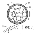
- FIG. 1 illustrates a cross-sectional view of a cylindrical electrostatographic imaging drum containing irregular foam chips.
- The present invention may be employed in any suitable electrostatographic imaging member comprising a substrate, an electrostatographic imaging layer, an imaging surface on said imaging layer and a back surface that generate high pitched ringing, squealing, squeaking, or howling sounds when utilized with a cleaning device such as a cleaning blade. However, for purposes of illustration, the invention will be described with reference to an electrophotographic imaging drum.
- Referring to FIG. 1, an electrostatographic imaging member assembly is illustrated comprising a hollow
electrostatographic imaging drum 10 comprising a hollowcylindrical substrate 12 and at least oneelectrophotographic imaging layer 14.Cylindrical substrate 12 may comprise any suitable material such as aluminum, nickel, plastic, and the like.Electrostatographic imaging layer 14 may comprise any suitable electrophotographic imaging material or an electrostatographic imaging material. Shown in contact with the outer imaging surface ofelectrophotographic imaging layer 14 is acleaning blade assembly 16 comprising a resilientelastomeric cleaning blade 18 supported by a relativelyrigid blade holder 20.Cleaning blade holder 20 may be supported by any suitable means such a machine housing (not shown) which also supports theelectrostatographic imaging drum 10.Cleaning blade 18 is conventional and well known in the art. Any suitable cleaning blade and cleaning blade holder may be used with the electrostatographic imaging member assembly of this invention. In operation,electrostatographic imaging member 10 is rotated in the direction shown by the arrow so that thecleaning blade assembly 18 rubs across the outer imaging surface oflayer 14 in a "doctor" or chiseling attitude. The stick-slip interaction between thecleaning blade 18 and the imaging surface ofimaging layer 14 can cause howling sounds to occur whenelectrostatographic imaging member 10 does not contain a porous gas filled acoustic dampening member block of this invention. - Shown in FIG. 1, is an electrostatographic imaging member assembly containing a plurality of expanded plastic foam pieces or
chips 24 as a porous gas filled acoustic dampening member.Sufficient chips 24 should be present to maintain firm pressure contact between the outermost chips and the interior surface ofsubstrate 12 so that at least some of the chips are at least partially compressed to ensure reduction or elimination of squealing or howling sounds that can occur when cleaningblade 18 contacts the outer imaging surface ofelectrostatographic imaging drum 10. - Any suitable preformed compressible resilient porous gas filled acoustic dampening member may be used in contact with the back surface of an electrostatographic imaging member assembly comprising an electrostatographic imaging member. The dampening means should be porous and contain gas filled cavities. The presence of gas in the dampening means is important because it is compressible and facilitates pressure contact with the back surface of the imaging member substrate. It is believed that imaging member resonance may be due a feedback phenomenon. The feedback appears to be due to an interaction between the cleaning blade and the imaging surface. The acoustic dampening means of this invention prevents such feedback. The vibrational energy transmitted to the partially compressed porous material causes the porous material to vibrate which in turn causes friction between the porous material the adjacent gas molecules as well as reflection and refraction of sound energy between cells each time the sound energy is absorbed thereby dissipating the vibrational energy. It is believed that this property causes the vibrational energy to be converted into heat energy through friction between solid material and adjacent gas molecules to convert the acoustic energy to heat energy. Sufficient energy must be absorbed by the acoustic dampening material to prevent squealing or howling, i.e., to prevent build up of sympathetic acoustic resonance of the drum due to cleaning blade sticking and slipping. In other words, the sound energy must be absorbed before feedback occurs. Thus, the porous gas filled acoustic dampening member utilized absorbs sound energy when placed in intimate compressive contact with the imaging member. The gas filled cavities may comprise open passages such as found in felt or open cell foam or it can comprise a plurality of closed cell cavities such as found in closed cell foam. The cavities may have any suitable shape such as spherical, oval, angular or the like. Also, the cavities may be of the same or different sizes. A typical average cavity diameter is about 5 micrometers, however, larger or smaller average cavity sizes may be utilized where suitable. Any suitable gas may be utilized. Typical gases include, for example, air, nitrogen, carbon dioxide, argon and the like. The solids in the porous dampening means of this invention should have a relatively large amount of surface area in contact with a gas. The acoustic dampening means is only partially compressed after installation and should retain sufficient gas molecules to assist in converting vibrational energy into heat energy. The acoustic dampening means of this invention should also have a compressibility factor of at least two to one and still return to its original shape. The acoustic dampening member should also be preformed prior to installation in the imaging member. In other words, prior to compression for insertion into the interior of the imaging member, it should have a definite shape to which it can return to after compressive pressure is applied and released. A preformed acoustic dampening member can easily be slid into place within the interior of the imaging member manually or by robotic means and readily removed for recycling at the end of imaging life of the imaging member. The degree of partial compression existing in the acoustic dampening member after installation also depends upon the resiliency of the acoustic dampening material used and the distortion resistance of the substrate utilized. Thus, for example, the amount of acoustic dampening member compression utilized for thin substrates should not be so great as to cause undesirable distortion of the substrate after installation of the acoustic dampening member. Materials such as solid rubber are compressible and return to their original shape, but do not contain a gas and are not compressible at a compressibility factor of at least two to one. Materials having a large mass are generally expensive to make, install, recycle, clean and reinstall. Also, high mass materials can impede acceleration of the cylindrical electrostatographic imaging member to operating speeds. Liquids should normally be avoided because liquids are not compressible. Compressibility, including the property of returning to its original shape, is important in order to cause the partially compressed compressible material to remain in place after installation in pressure contact with the back surface of the imaging member substrate as well as absorb sound energy. The porous materials preferably has a low mass. Preferred porous dampening means material include cork, sponge, felt, paper, cardboard, textile, opened cell foam, closed cell- foam, and the like. Typical foam materials include, for example, polyurethane foam, expanded polystyrene foam, expanded polyethylene foam, and the like.
- When utilized with cylindrical electrostatographic imaging members, the acoustic dampening means should rotate with the imaging member cylinder. Thus, the contact between the partially compressed acoustic dampening material and the inner surface of the cylindrical electrostatographic imaging member should be firm and sufficient to keep the acoustic dampening material in place so that it does not move or migrate.
- The acoustic dampening means should also be positioned in contact with at least the backside of the imaging member at or near the middle of the imaging member between the ends of a drum or the sides of a web. The percent of the length of the cylindrical electrostatographic imaging member in contact with the acoustic dampening material depends on factors such as the type of acoustic dampening material utilized and the circumferential arc contacted. Generally, at least about 10 percent of the length of the cylindrical electrostatographic imaging member is contacted with the acoustic dampening material. Preferably, contact should be with at least part of the region between about 33 percent to about 66 percent from one end of the drum or side of a web to the other end or side. Although an electrophotographic imaging drum may vibrate at three or four frequencies, the undesirable squealing or howling sound is believed to be due to a fundamental frequency having a node at the center of the drum. Thus, for a drum or cylinder, the porous gas filled acoustic dampening member is preferably in contact with a region of the hollow interior surface of the drum located from each end of the imaging member at a distance of up to about one third of the length of said cylindrical imaging member. Where a drum is utilized, and the region of contact between the porous gas filled acoustic dampening member and the interior surface of the drum is as little as between about 33 percent and about 66 percent of the length of the drum, the acoustic dampening member need not be in continuous contact with the entire circumferential band within that region. The effectiveness of the dampening material diminishes as the point of contact is further from the center of the drum and approaches one or the other end of the drum.
- Instead of continuous contact, a plurality of segments of the interior surface of the drum may be contacted by the acoustic dampening member. Generally, satisfactory results may be achieved when the sum of segmental contacts by the acoustic dampening member along a circumferential band extending around the interior of the drum equals at least about 85 percent of the circumference. Preferably the porous gas filled acoustic dampening member is in contact with at least about 90 percent of the interior circumference of the hollow interior surface of an electrostatographic imaging member. Optimum results are achieved when contact includes at least about 95 percent of the interior circumference. Since the area of each zone of segmental contact circumferentially or axially along a drum interior surface can be large or small and since the degree of acoustic damping can vary with the specific dampening, substrate and blade materials employed, some experimentation is desirable with specific combinations of materials utilized to determine the minimum amount contact sufficient to eliminate the undesirable squealing or howling sound created during contact between the imaging member and cleaning blade.
- The electrostatographic imaging member may comprise an electrophotographic imaging member or an electrographic imaging member. Electrophotographic imaging members and electrographic imaging members are well known in the art and may be of any suitable configuration such as, for example, a hollow cylinder or flexible belt. Electrostatographic imaging members usually comprise a supporting substrate having an electrically conductive surface. Electrophotographic imaging members also comprise at least one photoconductive layer. A blocking layer may optionally be positioned between the substrate and the photoconductive layer. If desired, an adhesive layer may optionally be utilized between the blocking layer and the photoconductive layer. For multilayered photoreceptors, a charge generation layer is usually applied onto the blocking layer and a charge transport layer is subsequently formed over the charge generation layer. For electrographic imaging members, an electrically insulating dielectric layer is applied directly onto the electrically conductive surface.
- The supporting substrate may be opaque or substantially transparent and may comprise numerous materials having the required mechanical properties. Accordingly, the substrate may comprise a layer of an electrically non-conductive or conductive material such as an inorganic or an organic composition. As electrically non-conducting materials there may be employed various resins known for this purpose including polyesters, polycarbonates, polyamides, polyurethanes, and the like. The electrically insulating or conductive substrate may be rigid or flexible and in the form of a hollow cylinder, an endless flexible belt or the like.
- The thickness of the supporting substrate layer depends on numerous factors, including beam strength, mechanical toughness, and economical considerations. Typical substrate layer thicknesses used for a flexible belt application may be of substantial thickness, for example, about 125 micrometers, or of a minimum thickness of not less than about 50 micrometers, provided that it produces no adverse effects on the belt. Typical substrate layer thicknesses used for a hollow cylinder application may range from about 25 micrometers to about 1,500 micrometers.
- The conductive layer may vary in thickness over substantially wide ranges depending on the optical transparency and degree of flexibility desired for the electrostatographic member. If the substrate is electrically conductive, a separate conductive layer may be unnecessary. For example if the substrate is a metal such as an electroformed nickel or thin walled aluminum tube, a separate conductive layer may be omitted.
- An optional hole blocking layer may be applied to the substrate or conductive layer for photoreceptors. The hole blocking layer should be continuous and have a dry thickness of less than about 0.2 micrometer. An optional adhesive layer may be applied to the blocking layer. Any suitable adhesive layer well known in the art may be utilized. Satisfactory results may be achieved with the adhesive layer thickness between about 0.05 micrometer and about 0.3 micrometer.
- Any suitable charge generating (photogenerating) layer may be applied onto the adhesive layer, blocking layer or conductive layer. Charge generating layers are well know in the art and can comprise homogeneous layers or photoconductive particles dispersed in a film forming binder. Other suitable photogenerating materials known in the art may also be utilized, if desired.
- Any suitable polymeric film forming binder material may be employed as the matrix in of the photogenerating layer.
- The photogenerating layer generally ranges in thickness from about 0.1 micrometer to about 5 micrometers, preferably from about 0.3 micrometer to about 3 micrometers. The photogenerating layer thickness is related to binder content. Higher binder content compositions generally require thicker layers for photogeneration.
- The charge transport layer may comprise any suitable transparent organic polymer or non-polymeric material capable of supporting the injection of photogenerated holes or electrons from the charge generating layer and allowing the transport of these holes or electrons through the organic layer to selectively discharge the surface charge. The charge transport layer not only serves to transport holes or electrons, but also protects the photoconductive layer from abrasion or chemical attack. The charge transport layer should exhibit negligible, if any, discharge when exposed to a wavelength of light useful in electrophotography. The charge transport layer in conjunction with the charge generating layer is an insulator to the extent that an electrostatic charge placed on the charge transport layer is not conducted in the absence of illumination. Charge transport layer materials are well known in the art.
- The charge transport layer may comprise activating compounds or charge transport molecules dispersed in normally, electrically inactive film forming polymeric materials. These charge transport molecules may be added to polymeric film forming materials.
- The thickness of the charge transport layer may range from about 10 micrometers to about 50 micrometers, and preferably from about 20 micrometers to about 35 micrometers. Optimum thicknesses may range from about 23 micrometers to about 31 micrometers.
- An optional conventional overcoating layer may also be used. The optional overcoating layer may comprise organic polymers or inorganic polymers that are electrically insulating or slightly semi-conductive. The overcoating layer may range in thickness from about 2 micrometers to about 8 micrometers, and preferably from about 3 micrometers to about 6 micrometers.
- For electrographic imaging members, a flexible dielectric layer overlying the conductive layer may be substituted for the photoconductive layers. Any suitable, conventional, flexible, electrically insulating dielectric polymer may be used in the dielectric layer of the electrographic imaging member.
Claims (2)
- An electrostatographic imaging member assembly comprising an electrostatographic imaging member (10) comprising a substrate (12), an electrostatographic imaging layer (14), an imaging surface on said imaging layer (14), a back surface on said substrate (12), and a preformed resilient porous gas filled acoustic dampening member (24) at least partially compressed and in pressure contact with said back surface, said pressure contact being sufficient to substantially eliminate relative movement between said substrate (12) and said acoustic dampening member (24) wherein at least about 10 percent of the length of said interior back surface of said imaging member (10) is in pressure contact with said preformed porous gas filled acoustic dampening member (24) and wherein said preformed porous gas filled acoustic dampening member is in the shape of chips, and wherein said preformed porous gas filled acoustic dampening member (24) is compressible at a ratio of at least about 2:1 and still return to its original shape.
- An electrostatographic imaging member assembly according to claim 1, wherein said preformed porous gas filled acoustic dampening member (24) is selected from the group consisting of cork, sponge, felt, paper, cardboard, textile, open cell foam and closed cell foam.
Applications Claiming Priority (2)
| Application Number | Priority Date | Filing Date | Title |
|---|---|---|---|
| US29656494A | 1994-08-26 | 1994-08-26 | |
| US296564 | 1994-08-26 |
Publications (3)
| Publication Number | Publication Date |
|---|---|
| EP0698829A2 EP0698829A2 (en) | 1996-02-28 |
| EP0698829A3 EP0698829A3 (en) | 1997-11-19 |
| EP0698829B1 true EP0698829B1 (en) | 2007-11-21 |
Family
ID=23142561
Family Applications (1)
| Application Number | Title | Priority Date | Filing Date |
|---|---|---|---|
| EP95305838A Expired - Lifetime EP0698829B1 (en) | 1994-08-26 | 1995-08-22 | Electrostatographic imaging member assembly |
Country Status (4)
| Country | Link |
|---|---|
| US (1) | US5722016A (en) |
| EP (1) | EP0698829B1 (en) |
| JP (1) | JPH0869233A (en) |
| DE (1) | DE69535648T2 (en) |
Cited By (1)
| Publication number | Priority date | Publication date | Assignee | Title |
|---|---|---|---|---|
| CN105286913A (en) * | 2014-07-14 | 2016-02-03 | 三星麦迪森株式会社 | ULTRASOUND BACKING MEMBER, AND METHOD OF MANUFACTURING THE ULTRASOUND BACKING MEMBER and ultrasound probe |
Families Citing this family (28)
| Publication number | Priority date | Publication date | Assignee | Title |
|---|---|---|---|---|
| KR100242117B1 (en) * | 1997-04-07 | 2000-02-01 | 윤종용 | Image forming apparatus for electro photographic processor |
| JP3973121B2 (en) * | 1997-08-21 | 2007-09-12 | 株式会社リコー | Electrophotographic photosensitive drum |
| US6075955A (en) * | 1998-01-23 | 2000-06-13 | Mitsubishi Chemical America, Inc. | Noise reducing device for photosensitive drum of an image forming apparatus |
| JPH11327415A (en) * | 1998-05-20 | 1999-11-26 | Nec Niigata Ltd | Photoreceptor drum for electrophotographic recording system |
| US5960236A (en) * | 1998-08-28 | 1999-09-28 | Xerox Corporation | Recycled silencer |
| JP4038932B2 (en) * | 1999-05-11 | 2008-01-30 | 富士電機デバイステクノロジー株式会社 | Electrophotographic photoreceptor |
| US6131003A (en) * | 1999-05-21 | 2000-10-10 | Mitsubishi Chemical America, Inc. | Noise reducing device for photosensitive drum of an image forming apparatus |
| US6212342B1 (en) * | 1999-08-11 | 2001-04-03 | Mitsubishi Chemical America, Inc. | Weighted noise reducing device for photosensitive drum of an image forming apparatus |
| US6470158B2 (en) * | 1999-08-11 | 2002-10-22 | Mitsubishi Chemical America, Inc. | Weighted noise reducing device for photosensitive drum of an image forming apparatus |
| US6208821B1 (en) * | 2000-03-31 | 2001-03-27 | Mitsubishi Chemical America, Inc. | Photosensitive drum having injection molded insert and method of forming same |
| US6406656B1 (en) * | 2000-04-18 | 2002-06-18 | Lexmark International, Inc. | Fabrication of photoconductor drum insert |
| US6813466B1 (en) | 2000-07-03 | 2004-11-02 | Eugene Francis Kopecky | Cleaning blade system for electrophotography |
| US6463250B1 (en) | 2000-10-04 | 2002-10-08 | Nexpress Solutions Llc | Externally heated deformable fuser roller |
| US6393247B1 (en) | 2000-10-04 | 2002-05-21 | Nexpress Solutions Llc | Toner fusing station having an internally heated fuser roller |
| US6456816B1 (en) | 2000-10-04 | 2002-09-24 | Nexpress Solutions Llc | Method and apparatus for an intermediate image transfer member |
| US6490430B1 (en) | 2000-10-04 | 2002-12-03 | Nexpress Solutions Llc | Externally heated roller for a toner fusing station |
| US6438338B1 (en) | 2000-10-19 | 2002-08-20 | Xerox Corporation | Extended life recycleable silencer assembly |
| US6572801B2 (en) * | 2000-12-22 | 2003-06-03 | Xerox Corporation | Method of forming an injection molded part having a zero draft side |
| JP2002244488A (en) * | 2001-02-13 | 2002-08-30 | Ricoh Co Ltd | Latent image carrier and image forming apparatus |
| JP2003043862A (en) | 2001-05-23 | 2003-02-14 | Ricoh Co Ltd | Latent image carrier, image forming apparatus, and vibration damping member |
| AU2002364134A1 (en) * | 2001-12-04 | 2003-06-17 | Thomas J. Beckey | Expandable plug and method of manufacture |
| US6553197B1 (en) | 2002-02-11 | 2003-04-22 | Xerox Corporation | Noise-free silencer assembly |
| US7769323B2 (en) * | 2007-02-21 | 2010-08-03 | Xerox Corporation | Acoustic dampening material for imaging drum |
| JP4762223B2 (en) * | 2007-12-06 | 2011-08-31 | 株式会社リコー | Temperature control device for electrophotographic photosensitive member substrate |
| US9004003B2 (en) * | 2009-06-25 | 2015-04-14 | Xerox Corporation | Apparatus for applying an acoustic dampening coating to the interior of a xerographic drum |
| JP5931711B2 (en) * | 2012-12-21 | 2016-06-08 | 京セラドキュメントソリューションズ株式会社 | Photosensitive drum, image forming apparatus, and vibration-proof structure |
| JP5737463B1 (en) | 2014-06-20 | 2015-06-17 | 富士ゼロックス株式会社 | Contact member, image carrier, and image forming apparatus |
| JP6661887B2 (en) * | 2015-03-16 | 2020-03-11 | 富士ゼロックス株式会社 | Support member, image carrier, image forming apparatus |
Family Cites Families (15)
| Publication number | Priority date | Publication date | Assignee | Title |
|---|---|---|---|---|
| US3646652A (en) * | 1969-05-15 | 1972-03-07 | Dayco Corp | Roller structure |
| GB1429518A (en) * | 1973-09-07 | 1976-03-24 | Xerox Corp | Resilient rollers |
| US4378622A (en) * | 1977-11-10 | 1983-04-05 | Dayco Corporation | Method of making compressible printing roller |
| JPS5830584B2 (en) * | 1978-07-26 | 1983-06-30 | キヤノン株式会社 | elastic roller |
| US4292386A (en) * | 1978-12-22 | 1981-09-29 | Tokyo Shibaura Denki Kabushiki Kaisha | Photoconductive drum with paper layer attachment |
| US4601963A (en) * | 1983-04-15 | 1986-07-22 | Ricoh Company, Ltd. | Locally deformable photosensitive drum for use in electrophotography |
| JPS6360480A (en) * | 1986-08-30 | 1988-03-16 | Mita Ind Co Ltd | Recorder |
| JPS6360481A (en) * | 1986-08-30 | 1988-03-16 | Mita Ind Co Ltd | Recorder |
| JPS63271388A (en) * | 1987-04-30 | 1988-11-09 | Toshiba Corp | Image forming device |
| JPH02118684A (en) * | 1988-10-28 | 1990-05-02 | Nec Corp | Process cartridge |
| JPH0535167A (en) * | 1991-08-03 | 1993-02-12 | Canon Inc | Image holding member, process cartridge and image forming apparatus using the same |
| JPH0535166A (en) * | 1991-07-31 | 1993-02-12 | Canon Inc | Image forming device |
| US5160421A (en) | 1991-12-02 | 1992-11-03 | Xerox Corporation | Electroforms with high dimensional stability |
| JPH05188839A (en) * | 1992-01-07 | 1993-07-30 | Canon Inc | Image forming device |
| JPH05281773A (en) * | 1992-04-03 | 1993-10-29 | Canon Inc | Image carrier drum, image forming device and process cartridge |
-
1995
- 1995-08-18 JP JP7210265A patent/JPH0869233A/en not_active Withdrawn
- 1995-08-22 DE DE69535648T patent/DE69535648T2/en not_active Expired - Lifetime
- 1995-08-22 EP EP95305838A patent/EP0698829B1/en not_active Expired - Lifetime
- 1995-11-28 US US08/748,890 patent/US5722016A/en not_active Expired - Lifetime
Cited By (1)
| Publication number | Priority date | Publication date | Assignee | Title |
|---|---|---|---|---|
| CN105286913A (en) * | 2014-07-14 | 2016-02-03 | 三星麦迪森株式会社 | ULTRASOUND BACKING MEMBER, AND METHOD OF MANUFACTURING THE ULTRASOUND BACKING MEMBER and ultrasound probe |
Also Published As
| Publication number | Publication date |
|---|---|
| JPH0869233A (en) | 1996-03-12 |
| DE69535648T2 (en) | 2008-03-20 |
| US5722016A (en) | 1998-02-24 |
| DE69535648D1 (en) | 2008-01-03 |
| EP0698829A3 (en) | 1997-11-19 |
| EP0698829A2 (en) | 1996-02-28 |
Similar Documents
| Publication | Publication Date | Title |
|---|---|---|
| US5722016A (en) | Electrostatographic imaging member assembly | |
| US5960236A (en) | Recycled silencer | |
| EP0698828B1 (en) | Electrostatographic imaging member assembly | |
| US5430526A (en) | Image forming apparatus having weighting material in image bearing member and process cartridge usable with same | |
| US3923392A (en) | Electrophotographic copier | |
| US3989005A (en) | Oil metering blade device | |
| US4601963A (en) | Locally deformable photosensitive drum for use in electrophotography | |
| US3980424A (en) | Fuser cleaning roller | |
| US3988817A (en) | Pressure roll for dry fuser apparatus | |
| US3536397A (en) | Xerographic apparatus | |
| EP1103863B1 (en) | Developing device for an image forming apparatus | |
| US6626427B2 (en) | Adaptive sheet feeding roll | |
| US5822169A (en) | Contact charging device | |
| US6438338B1 (en) | Extended life recycleable silencer assembly | |
| US5130755A (en) | Cleaning device | |
| KR100459941B1 (en) | Image carrier and damping member therefor | |
| US6418297B1 (en) | Cleaning apparatus featuring a vibrating toner carrier feature of specified length and image forming apparatus using same | |
| JP3656667B2 (en) | Electrophotographic image carrier and image forming apparatus using the same | |
| JPH05188839A (en) | Image forming device | |
| US3966394A (en) | Plural cleaning rolls assembly | |
| US5327197A (en) | Electrophotographic apparatus | |
| US7769323B2 (en) | Acoustic dampening material for imaging drum | |
| US3980423A (en) | Fuser cleaning roll assembly | |
| US6553197B1 (en) | Noise-free silencer assembly | |
| JPH05158387A (en) | Image forming device |
Legal Events
| Date | Code | Title | Description |
|---|---|---|---|
| PUAI | Public reference made under article 153(3) epc to a published international application that has entered the european phase |
Free format text: ORIGINAL CODE: 0009012 |
|
| AK | Designated contracting states |
Kind code of ref document: A2 Designated state(s): DE FR GB |
|
| PUAL | Search report despatched |
Free format text: ORIGINAL CODE: 0009013 |
|
| AK | Designated contracting states |
Kind code of ref document: A3 Designated state(s): DE FR GB |
|
| 17P | Request for examination filed |
Effective date: 19980519 |
|
| 17Q | First examination report despatched |
Effective date: 19990621 |
|
| GRAP | Despatch of communication of intention to grant a patent |
Free format text: ORIGINAL CODE: EPIDOSNIGR1 |
|
| GRAS | Grant fee paid |
Free format text: ORIGINAL CODE: EPIDOSNIGR3 |
|
| GRAA | (expected) grant |
Free format text: ORIGINAL CODE: 0009210 |
|
| AK | Designated contracting states |
Kind code of ref document: B1 Designated state(s): DE FR GB |
|
| REG | Reference to a national code |
Ref country code: GB Ref legal event code: FG4D |
|
| REF | Corresponds to: |
Ref document number: 69535648 Country of ref document: DE Date of ref document: 20080103 Kind code of ref document: P |
|
| ET | Fr: translation filed | ||
| PLBE | No opposition filed within time limit |
Free format text: ORIGINAL CODE: 0009261 |
|
| STAA | Information on the status of an ep patent application or granted ep patent |
Free format text: STATUS: NO OPPOSITION FILED WITHIN TIME LIMIT |
|
| 26N | No opposition filed |
Effective date: 20080822 |
|
| PGFP | Annual fee paid to national office [announced via postgrant information from national office to epo] |
Ref country code: FR Payment date: 20100824 Year of fee payment: 16 Ref country code: DE Payment date: 20100818 Year of fee payment: 16 |
|
| PGFP | Annual fee paid to national office [announced via postgrant information from national office to epo] |
Ref country code: GB Payment date: 20100818 Year of fee payment: 16 |
|
| GBPC | Gb: european patent ceased through non-payment of renewal fee |
Effective date: 20110822 |
|
| REG | Reference to a national code |
Ref country code: FR Ref legal event code: ST Effective date: 20120430 |
|
| REG | Reference to a national code |
Ref country code: DE Ref legal event code: R119 Ref document number: 69535648 Country of ref document: DE Effective date: 20120301 |
|
| PG25 | Lapsed in a contracting state [announced via postgrant information from national office to epo] |
Ref country code: GB Free format text: LAPSE BECAUSE OF NON-PAYMENT OF DUE FEES Effective date: 20110822 Ref country code: FR Free format text: LAPSE BECAUSE OF NON-PAYMENT OF DUE FEES Effective date: 20110831 |
|
| PG25 | Lapsed in a contracting state [announced via postgrant information from national office to epo] |
Ref country code: DE Free format text: LAPSE BECAUSE OF NON-PAYMENT OF DUE FEES Effective date: 20120301 |