EP0698309B1 - Phase-shifting apparatus for interconnecting two synchronous polyphase ac networks - Google Patents
Phase-shifting apparatus for interconnecting two synchronous polyphase ac networks Download PDFInfo
- Publication number
- EP0698309B1 EP0698309B1 EP94915007A EP94915007A EP0698309B1 EP 0698309 B1 EP0698309 B1 EP 0698309B1 EP 94915007 A EP94915007 A EP 94915007A EP 94915007 A EP94915007 A EP 94915007A EP 0698309 B1 EP0698309 B1 EP 0698309B1
- Authority
- EP
- European Patent Office
- Prior art keywords
- phase
- transformer
- networks
- secondary windings
- shifting
- Prior art date
- Legal status (The legal status is an assumption and is not a legal conclusion. Google has not performed a legal analysis and makes no representation as to the accuracy of the status listed.)
- Expired - Lifetime
Links
Images







Classifications
-
- H—ELECTRICITY
- H02—GENERATION; CONVERSION OR DISTRIBUTION OF ELECTRIC POWER
- H02J—ELECTRIC POWER NETWORKS; CIRCUIT ARRANGEMENTS OR SYSTEMS FOR SUPPLYING OR DISTRIBUTING ELECTRIC POWER; SYSTEMS FOR STORING ELECTRIC ENERGY
- H02J3/00—Circuit arrangements for AC mains or AC distribution networks
- H02J3/38—Arrangements for feeding a single network from two or more generators or sources in parallel; Arrangements for feeding already energised networks from additional generators or sources in parallel
- H02J3/46—Controlling the sharing of generated power between the generators, sources or networks
-
- H—ELECTRICITY
- H02—GENERATION; CONVERSION OR DISTRIBUTION OF ELECTRIC POWER
- H02J—ELECTRIC POWER NETWORKS; CIRCUIT ARRANGEMENTS OR SYSTEMS FOR SUPPLYING OR DISTRIBUTING ELECTRIC POWER; SYSTEMS FOR STORING ELECTRIC ENERGY
- H02J3/00—Circuit arrangements for AC mains or AC distribution networks
- H02J3/04—Arrangements for connecting networks of the same frequency but supplied from different sources
- H02J3/06—Controlling the transfer of power between connected networks; Controlling load sharing between connected networks
-
- H—ELECTRICITY
- H02—GENERATION; CONVERSION OR DISTRIBUTION OF ELECTRIC POWER
- H02J—ELECTRIC POWER NETWORKS; CIRCUIT ARRANGEMENTS OR SYSTEMS FOR SUPPLYING OR DISTRIBUTING ELECTRIC POWER; SYSTEMS FOR STORING ELECTRIC ENERGY
- H02J3/00—Circuit arrangements for AC mains or AC distribution networks
- H02J3/38—Arrangements for feeding a single network from two or more generators or sources in parallel; Arrangements for feeding already energised networks from additional generators or sources in parallel
-
- H—ELECTRICITY
- H02—GENERATION; CONVERSION OR DISTRIBUTION OF ELECTRIC POWER
- H02J—ELECTRIC POWER NETWORKS; CIRCUIT ARRANGEMENTS OR SYSTEMS FOR SUPPLYING OR DISTRIBUTING ELECTRIC POWER; SYSTEMS FOR STORING ELECTRIC ENERGY
- H02J3/00—Circuit arrangements for AC mains or AC distribution networks
- H02J3/38—Arrangements for feeding a single network from two or more generators or sources in parallel; Arrangements for feeding already energised networks from additional generators or sources in parallel
- H02J3/40—Synchronisation of generators for connection to a network or to another generator
Definitions
- the invention generally relates to AC network interconnections using susceptances, and more specifically to a phase-shifting interconnecting apparatus to control power transfers between two synchronous polyphase AC networks.
- phase shifted voltages applied to susceptances of prior AC network interconnecting apparatus are produced by means of phase transposition devices and/or a judicious selection of transformer windings (e.g. combinations of Y-y, Y-d1, Y-y6, etc, - connected windings).
- transformer windings e.g. combinations of Y-y, Y-d1, Y-y6, etc, - connected windings.
- phase-shift angles around 360° can be obtained with partial zigzag combinations of transformer windings for the prior interconnecting apparatus, such topography is not considered in practice for reasons of efficiency.
- the interconnector further comprises a switch device arranged to insert a linear reactor in series in the circuit only during contingency. In every case, an action is required to insert the linear reactor which has the sole purpose of limiting fault currents. During normal operation, the linear reactor is shunted by the switch device.
- phase-shifting interconnecting apparatus which overcomes the above-mentioned drawbacks of the prior art methods and interconnecting apparatus, by implementing a method of phase-shifting voltages applied to susceptances used to interconnect two synchronous AC networks, in order to control power transfers between the two synchronous polyphase AC networks.
- Another object of the invention is to provide such a phase-shifting interconnecting apparatus using transformers having appreciable reduced sizes and MVA ratings with respect to the transformers required by the interconnecting apparatus of the prior art.
- Another object of the present invention is to provide such an interconnecting apparatus which is effective and operative for a continuum of available phase-shift angles.
- a phase-shifting interconnecting apparatus for interconnecting respective phase lines of first and second synchronous polyphase AC networks, said apparatus comprising, for each pair of respective phase lines subjected to an interconnection, a pair of circuit branches in-parallel including respectively inductive and capacitive susceptances subjected to properly phase shifted voltages, each said pair of circuit branches having first and second common branch points provided with connecting means for connecting respectively said branch points to said respective phase lines; said apparatus being characterised in that : at least one of said susceptances in each of said pairs of circuit branches is subjected to a voltage which is phase shifted using a series transformer means including at least one primary winding having at least a portion connected in series with said at least one of said susceptances, and at least one secondary winding having at least a portion adapted to receive an excitation voltage derived from said AC networks, said excitation voltage having a phase angle with respect to a phase voltage provided by one of said respective phase lines, whereby, in operation, said excitation
- the phase-shifting interconnecting apparatus further comprises means for changing an angle of phase-shifting produced by each said series transformer means.
- these means for changing comprise a tap changer associated with each said at least one primary winding, to adjust said at least a portion thereof connected in series with said at least one of said susceptances.
- these means for changing comprise excitation transformer means for modulating each said excitation voltage, said excitation transformer means having primary windings arranged respectively to receive phase voltages of said first AC network, and secondary windings provided with tap changers or adjusters, for producing respectively adjustable voltages in phase with the phase voltages of the first AC network, each said excitation voltage being derived from at least a corresponding one of said adjustable voltages.
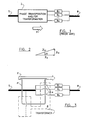
- FIG. 1 there is shown a schematic diagram illustrating the principle on which prior art interconnecting apparatus work for controlling power conditions between a first three-phase AC network S (for S ource) and a second three-phase AC network R (for R eceiver).
- phase-shifted voltages applied to susceptances B 1 , B 2 ..., B n are produced by adequate phase transposition device and/or transformer with Y, ⁇ and/or zigzag (ZZ) -connected windings, as depicted by box 2.
- the whole power, as represented by arrow P, transferred from the AC network S to the AC network R flows throughout the phase transposition device and/or transformer 2 which must be dimensioned for this purpose.
- the method according to the present invention involves phase-shifting mechanisms for producing phase-shifts ⁇ , required by the susceptances B 1 , B 2 ..., B n . More particularly, the method consists in adding to a voltage V S derived for example from the AC network S a relatively small voltage V Q preferably in quadrature to obtain a resulting voltage V S1 having a modulus approximately equal to the modulus of the voltage V S but with a different phase.
- the small voltage V Q is generated by inducing in a primary winding 4 of a relatively small transformer 6 a phase-shifted fraction of a phase voltage of the AC network S.
- the primary winding 4 is connected in series with the considered susceptance B 1 , B 2 ..., B n .
- the voltage V S1 upstream (on the side of the AC network S with respect to a susceptance) from the susceptance B 1 , B 2 ..., B n results therefore from a vectorial addition of the phase voltage V S and the voltage V Q in the primary winding 4, and exhibits phase-shift characteristics as shown in Figure 2.
- an interconnecting apparatus normally comprises several susceptances B 1 , B 2 ..., B n (of capacitive and inductive types) to which are applied as many voltages from different phases, it is possible to use several primary windings 4 to produce the desired voltages (the primary windings 4 are generally associated with different phases).
- Advantage of such a topography lies in appreciable size reduction of the transformer 6 and its MVA ratings since only a fraction P' of the power P transferred by the interconnecting apparatus flows in the transformer 6. This advantage prevails especially for small angles of phase shifts ⁇ .
- Another advantage lies in the fact that the available angles of phase shifts ⁇ are not limited to multiple of 30°. Indeed, the modulus of the small voltage vector V Q can be modified by varying slightly the transformer ratios, changing thereby the phase-shifting effects. A continuum of angles of phase shifts ⁇ is therefore available.
- the small voltage V Q must not necessarily be at 90° (in quadrature) from the phase voltage V S .
- angle of voltage injection addition of a small voltage to the phase voltage of a three-phase AC network for producing a new voltage generally having a similar modulus but with a different phase
- another angle is more appropriate.
- the case at 120° worth mentioning since it can be easily obtained from the voltage of another phase in a three-phase system.
- the injection at 120° has the advantage to limit the modulus increase of the voltage V S1 when operating with large values of ⁇ .
- the injection at 90° is for its part obtained from the line-line voltage of two other phases (as V SB , V SC ).
- phase-shifting device For limiting this current, a classical phase-shifting device must continuously react to angular variations and even to variations of modulus. In some cases, a phase-shifting device having two degrees of freedom (modulus and angle) is required to carry out this task.
- susceptances are inserted in series with the phase-shifting device. Their properties are to act as buffers to the voltage, modulus and angle variations of the AC network, and make the transfer of active and reactive power much less sensible to these variations. Similarly, a small difference of modulus between V S and V S1 has almost no influence on the power transfer and can be therefore neglected, although its effects can be completely compensated by readjusting somewhat the values of the susceptances during design.
- the method of phase-shifting a voltage (e.g. V SA1 ) applied to at least one susceptance B interconnecting a phase line of a first polyphase AC network S with a corresponding phase line of a second polyphase AC network R, both AC networks being synchronous comprises the steps of:
- the method may comprise the additional step of changing an angle of phase-shifting produced by the transformer. This can be carried out for example either by adjusting the portion of the primary winding connected in series with the susceptance, or by modulating an amplitude of the excitation voltage, for changing the phase-shifting.
- the excitation voltages can have for example phase angles of ⁇ 90° or ⁇ 120° with respect to the phase voltage V SA by selecting the appropriate manner to use the phase voltages provided by the AC networks. Various other phase angles are also available by means of these phase voltages or other voltages derived thereof.
- phase-shifting interconnecting apparatus can take various topologies as shown in the Figures, which are all just as well advantageous depending on the operating conditions of the AC networks S and R and the desired power transfers therebetween.
- the phase-shifting interconnecting apparatus interconnects respective phase lines (e.g. phases A-A, B-B, etc.) of first and second synchronous polyphase AC networks S, R.
- the apparatus comprises, for each pair of respective phase lines subjected to an interconnection, a pair of circuit branches in parallel, having first and second common branch points 8, 10 provided with connectors for connecting respectively the branch points 8, 10 to the respective phase lines.
- These circuit branches include respectively inductive and capacitive susceptances 12, 14.
- the apparatus also comprises a series transformer arrangement for phase-shifting a voltage applied to at least one of the susceptances 12, 14.
- This series transformer arrangement includes at least one primary winding 17 having at least a portion connected in series with one of the susceptances 12, 14, and at least one secondary winding 19 having at least a portion adapted to receive an excitation voltage derived from the AC networks so as to have a phase angle with respect to a phase voltage provided by one of the respective phase lines.
- the excitation voltage combines through the transformer with the phase voltage to cause phase-shifting of the voltage applied to the susceptance 12, 14.
- the phase-shifting interconnecting apparatus can further comprises mechanisms for changing angles of phase-shifting produced by the series transformer arrangements. As shown in Figure 22, these mechanisms may be obtained by means of tap changers 78 associated with the primary windings 30, 32, 34, to adjust portions thereof connected in series with the susceptances 12, 14. As shown in Figure 8, these mechanisms may also be obtained by means of excitation transformer arrangements 18 for modulating each excitation voltage.
- the excitation transformer arrangements 18 have primary windings 20 for receiving respectively the phase voltages of the first AC network S, and secondary windings 22 provided with tap changers or ratio adjusters 24, for producing respectively adjustable voltages in phase with the phase voltages of the first AC network S. Each excitation voltage is derived from at least a corresponding one of the adjustable voltages.
- the phase-shift effects are thus adjustable by modulating amplitude of the adjustable voltages by means of the tap changers or ratio adjusters 24.
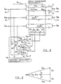
- a phase-shifting interconnecting apparatus for interconnecting three-phase AC networks, including first and second three-phase transformers providing respectively the series transformer arrangements 16 and the excitation transformer arrangements 18.
- the first three-phase transformer has three pairs of primary windings 30, 32, 34 magnetically coupled respectively with three ⁇ -connected secondary windings 36, 38, 40, while the second three-phase transformer has three primary windings 42, 44 , 46 magnetically coupled respectively with three secondary windings 48, 50, 52 with grounded low voltage tap changers 24.
- Each of the primary windings 42, 44, 46 of the second three-phase transformer is connected between a ground and a corresponding one of the first branch points 8, and each of the secondary windings 48, 50, 52 of the second three-phase transformer is connected to a corresponding interconnecting point of the ⁇ -connected secondary windings 36, 38, 40 of the first three-phase transformer.
- the use of the excitation transformer arrangements 18 allows modulation of the injected voltages by means of the tap changers 24 (or ratio adjusters or any other suitable devices).
- the phase shifts ⁇ and hence the power transfers of active and/or reactive power are thus variable.
- Inversion of the power flow P SR (to a power flow P RS ) is achieved at low voltage by means of power reversal switches 26 connected between the secondary windings 36, 38, 40 of the first three-phase transformer and the secondary windings 48, 50, 52 of the second three-phase transformer 18, for switching between two winding terminal connections of each secondary windings 48, 50, 52.
- the signs of the phase shifts ⁇ are thereby changed.
- the turns ratios (n SE1 , n SE2 ) of the primary windings 30, 32, 34 of the first three-phase transformer may be chosen with different values during construction of the phase-shift interphase power controller so as to obtain nonsymmetrical phase shifts ⁇ , for the inductive and capacitive susceptances 12, 14. In operation, however, the phase shifts ⁇ can only vary together since each of the pairs of primary windings 30, 32, 34 is coupled with a single corresponding common secondary winding 36, 38, 40, as depicted by symbols , , ⁇ .
- FIG. 9 there is shown a phase diagram of upstream and downstream voltages V SA , V RA (phase voltages), phase-shifted voltages V SA1 , V SA2 and susceptance voltages V LA , V CA for phase A of the phase-shifting interconnecting apparatus shown in Figure 8 where the phase voltages V SA , V RA are in phase.
- FIG. 10 there is shown a second embodiment of a phase-shifting interconnecting apparatus, similar to the first embodiment with the few exception that the injection is carried out at 60° instead of in quadrature.
- the difference is in the manner to connect the series transformer arrangements 16.
- the turns ratios (n SE1 , n SE2 ) of the primary windings 17 should be in that case revised to adapt the new excitation voltage obtained with this topography and the values of the susceptances 12, 14 should also be adjusted to take into account changes in the modulus of the phase-shifted voltages V SA1 and V SA2 as shown in the corresponding phase diagram of Figure 11.
- the first three-phase transformer providing the series transformer arrangements 16 has three pairs of primary windings 30, 32, 34 magnetically coupled respectively with three ground-connected secondary windings 36, 38, 40.
- the second three-phase transformer providing the excitation transformer arrangements 18 has three primary windings 42, 44, 46 magnetically coupled respectively with three secondary windings 48, 50, 52 with grounded tap changers 24.
- Each of the primary windings 42, 44, 46 of the second three-phase transformer are connected between a ground and a corresponding one of the first branch points 8, while each of the secondary windings 48, 50, 52 of the second three-phase transformer are connected to a corresponding one of the ground-connected secondary windings 36, 38, 40 of the first three-phase transformer.
- first and second three-phase transformers provide the series transformer arrangement 16, each having three primary windings 54, 56, 58 magnetically coupled respectively with three ⁇ -connected secondary windings 60, 62, 64.
- a third three-phase transformer provides the excitation transformer arrangements 18, having three primary windings 66, 68, 70 magnetically coupled respectively with three pairs of secondary windings 72, 74, 76 with grounded tap changers 24.
- Each of the primary windings 66, 68, 70 of the third three-phase transformer are connected between a ground and a corresponding one of the first branch points 8, whereas each of the pairs of the secondary windings 72, 74, 76 of the third three-phase transformer are connected to corresponding interconnecting points of the ⁇ -connected secondary windings 60, 62, 64 of the first and second three-phase transformer respectively.
- FIG 14 there is shown a fourth embodiment of a phase-shifting interconnecting apparatus, which has no excitation transformer arrangement, and which exhibits the phase-shifting features as shown in Figure 15.
- This topography is based on the fact that the phase-shifting interconnecting apparatus does not require precise adjustment of its series transformer arrangements 16.
- the excitation transformer arrangements 18 (as shown in Figure 8) can be removed since their tap changers 24 become useless.
- the secondary windings of the series transformer arrangements 16 can then be directly powered from the upstream voltages V SA , V SB , V SC (phase voltages) of the first AC network S, saving thus as many MVA of transformation.
- phase-shifting interconnecting apparatus With the exception of absence of excitation transformer arrangements and a relocation of the power reversal switches 26, this topology of the phase-shifting interconnecting apparatus also resembles the first embodiment. If a row of power operating points is nevertheless desired, it remains still possible to provide groups of discrete susceptances selectable by means of suitable switches (not shown) as in the case of classical interconnecting apparatus.
- the three-phase transformer providing the series transformer arrangements has three pairs of primary windings 30, 32, 34 magnetically coupled respectively with three ⁇ -connected secondary windings 36, 38, 40.
- Each of the first branch points 8 are connected to a corresponding interconnecting point of the ⁇ -connected secondary windings 36, 38, 40 of the three-phase transformer.
- the power reversal switches 26 are connected between the primary windings 17 and the susceptances 12, 14, for switching positions of the susceptances 12, 14 with respect to the primary windings 17.
- FIG 16 there is shown a fifth embodiment of a phase-shifting interconnecting apparatus, which also has no excitation transformer arrangement, and which exhibits the phase-shifting features as shown in Figure 17.
- this topography combines the properties and characteristics of the phase-shift interconnecting apparatus shown in Figures 10 and 14.
- the three-phase transformer providing the series transformer arrangements 18 has three pairs of primary windings 30, 32, 34 magnetically coupled respectively with three ground-connected secondary windings 36, 38, 40.
- Each of the first branch points 8 are connected to a corresponding one of the ground-connected secondary windings 36, 38, 40 of the three-phase transformer.
- phase-shift interphase power controller which also has no excitation transformer arrangement, and which exhibits the phase-shifting features as shown in
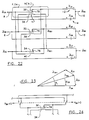
- FIG. 20 there are shown schematic diagrams of circuit branches of a phase-shifting interconnecting apparatus, for phase-shifting a single voltage applied either on the inductive or capacitive susceptance.
- V S and V R represent respectively the phase-ground voltages of the AC networks S and R.
- phase-shifting interconnecting apparatus having phase-shifting transformer arrangements in a squashed delta configuration.
- This configuration matches advantageously the network characteristics and provides the phase-shifting features shown by the phase diagram in Figure 23, which are given by:
- All of the series transformer arrangements are provided by a three-phase transformer having three primary windings 30, 32, 34 magnetically coupled respectively with three secondary windings 36, 38, 40.
- Each of the primary windings 30, 32, 34 is provided with a tap terminal 78 connected to a corresponding one of the susceptances 12, 14.
- Each of the secondary windings 36, 38, 40 is connected between a corresponding one of the first branch points 8 and one of the tap terminals 78.
- FIG 24 there is shown a power reversal switch circuit specially adapted for the phase-shifting interconnecting apparatus shown in Figure 22.
- the switch circuit simply interchanges the series connections of the primary windings 30, 32, 34 to reverse the power flow.
- phase-shifting interconnecting apparatus having phase-shifting transformer arrangements in a Mersereau configuration.
- All of the series transformer arrangements 16 are provided by a first three-phase transformer having three primary windings 30, 32, 34 magnetically coupled respectively with three ⁇ -connected secondary windings 36, 38, 40.
- All of the excitation transformer arrangements 18 are provided by a second three-phase transformer having three primary windings 42, 44, 46 magnetically coupled respectively with three secondary windings 48, 50, 52 with grounded tap changers 24.
- Each of the primary windings 30, 32, 34 of the first three-phase transformer is provided with a tap terminal 25.
- Each of the primary windings 42, 44, 46 of the second three-phase transformer is connected between a ground and a corresponding one of the tap terminals 25.
- Each of the secondary windings 48, 50, 52 of the second three-phase transformer is connected to a corresponding interconnecting point of the ⁇ -connected secondary windings 36, 38, 40 of the first three-phase transformer.
- the phase-shifting features of this interconnecting apparatus are shown in Figure 26.
- the global ratio i.e. the combined ratio of the first and second three-phase transformers
- n ( ⁇ 1 ) 2tan - ⁇ 1 2
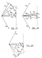
- phase diagrams of voltage vectors relative to 3 modes of operation of a phase-shifting interconnecting apparatus for hexaphase AC networks namely a "M30" mode where V SA has a phase angle around -30° with respect to V RA , a "Centered” mode where V SA has a phase angle around 0° with respect to V RA , and a "P30” mode where V SA has a phase angle around +30° with respect to V RA .
- FIG. 30 there is shown an embodiment of a phase-shifting interconnecting apparatus for hexaphase AC networks.
- the principles involved in phase-shifting the voltages applied to the susceptances 12, 14 are the same as for three-phase AC networks, except that the number of phase lines to interconnect is doubled.
- Example of series transformer arrangements F.31 and excitation transformer arrangements F.32 for the apparatus are respectively shown in Figures 31 and 32. All of the series transformer arrangements F.31 are provided by first and second three-phase transformers both having three pairs of primary windings 80, 82, 84, and 86, 88, 90 magnetically coupled respectively with three ⁇ -connected secondary windings 92, 94, 96, and 98, 100, 102.
- All of the excitation transformer arrangements F.32 are provided by third and fourth three-phase transformers both having three primary windings 104, 106, 108, and 110, 112, 114 magnetically coupled respectively with three secondary windings 116, 118, 120 and 122, 124, 126 with grounded tap changers 128, 130.
- Each of the primary windings 104, 106, 108, and 110, 112, 114 of the third and fourth three-phase transformers are connected between a ground and a corresponding one of the first branch points 8.
- Each of the secondary windings 116, 118, 120, and 122, 124, 126 of the third and fourth three-phase transformers are connected to a corresponding interconnecting point of the ⁇ -connected secondary windings 92, 94, 96, and 98, 100, 102.
- the three modes of operation of the apparatus are selected by means of a mode selecting switch circuit connected between the series transformer arrangements F.31 and the susceptances 12, 14 as shown in Figure 33, in combination with other switches 132 connected between the series transformer arrangements F.31 and the excitation transformer arrangements F.32.
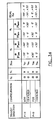
- the characteristics pertaining to each mode of operation are reported in a table in Figure 34, for a phase A of the hexaphase AC networks.
- the characteristics for the other phases are obtained by replacing the subscripts by the cyclic permutation A ⁇ B ⁇ C ⁇ D ⁇ E ⁇ F ⁇ A.
- Figure 35 shows another embodiment of a phase-shifting interconnecting apparatus for hexaphase AC networks, having series transformer arrangements 16 in a squashed delta configuration. All of the series transformer means are provided by first and second three-phase transformers both having three primary windings 134, 136, 138, and 140, 142, 144 magnetically coupled respectively with three secondary windings 146, 148, 150, and 152, 154, 156. Each of the primary windings 134, 136, 138, and 140, 142, 144 is provided with a tap terminal 158 connected to a corresponding one of the susceptances 12, 14. Each of the secondary windings 146, 148, 150 and 152, 154, 156 is connected between a corresponding one of the first branch points 8 and one of the tap terminals 158.
- the susceptances of the phase-shifting interconnecting apparatus can be divided in two equal parts for protecting the phase-shifting device(s) against high fault currents.
- the power characteristics of the interconnecting apparatus remain the same.
Landscapes
- Engineering & Computer Science (AREA)
- Power Engineering (AREA)
- Ac-Ac Conversion (AREA)
- Supply And Distribution Of Alternating Current (AREA)
- Emergency Protection Circuit Devices (AREA)
- Power Conversion In General (AREA)
Abstract
Description
- The invention generally relates to AC network interconnections using susceptances, and more specifically to a phase-shifting interconnecting apparatus to control power transfers between two synchronous polyphase AC networks.
- Hitherto, phase shifted voltages applied to susceptances of prior AC network interconnecting apparatus are produced by means of phase transposition devices and/or a judicious selection of transformer windings (e.g. combinations of Y-y, Y-d1, Y-y6, etc, - connected windings). Thus, it is possible to provide multiple angles of voltage phase-shifts by step of 30° around a complete 360° range. This method however has the drawback to require a transformer dimensioned to sustain the circulation of the whole power transferred by the interconnecting apparatus.
- Moreover, although a continuum of phase-shift angles around 360° can be obtained with partial zigzag combinations of transformer windings for the prior interconnecting apparatus, such topography is not considered in practice for reasons of efficiency.
- Known in the art is an article entitled "Developments of A.C. type system interconnectors" published in May 1972, IEEE Transactions on Power Apparatus and Systems, vol. PAS-91, no. 3, pp. 1085-1092. The article describes an AC system interconnector comprising a series transformer with a leakage impedance necessary for the suppression of fault currents. The series transformer is provided with a secondary winding which is given, through a regulating transformer, compensation voltage for the voltage drop across the series transformer due to normal power flow. This causes a reduction of the apparent impendance between interconnected adjacent blocks. The interconnector further comprises a switch device arranged to insert a linear reactor in series in the circuit only during contingency. In every case, an action is required to insert the linear reactor which has the sole purpose of limiting fault currents. During normal operation, the linear reactor is shunted by the switch device.
- Also known in the art is an article entitled "Experiences with parallel EHV phase shifting transformers" published in July 1991, IEEE Transactions on Power Delivery, vol. 6, no. 3, pp. 1096-1100. The article describes an apparatus comprising phase-shifting transformers using voltage injection to provide phase shifts between two AC networks. In order to solve the problems related to the paralleling of phase-shifting transformers, the apparatus involves a complex system of control and protection to avoid any flowing current.
- Also known in the art is US patent no. 4,621,198 (Roberge et al.) which describes an apparatus as specified in the preamble of
claim 1, comprising parallel branches, each of which includes a susceptance to which a phase shifted voltage is applied individually. The apparatus comprises, for each phase, three principal branches in parallel, and the phase shifts applied to the susceptances are provided by simple phase permutation (fixed values at multiples of ±120°). Each of the branches includes two sub-branches in parallel, one of which is inductive, and the other is capacitive. - It is therefore an object of the invention to provide a phase-shifting interconnecting apparatus which overcomes the above-mentioned drawbacks of the prior art methods and interconnecting apparatus, by implementing a method of phase-shifting voltages applied to susceptances used to interconnect two synchronous AC networks, in order to control power transfers between the two synchronous polyphase AC networks.
- Another object of the invention is to provide such a phase-shifting interconnecting apparatus using transformers having appreciable reduced sizes and MVA ratings with respect to the transformers required by the interconnecting apparatus of the prior art. Another object of the present invention is to provide such an interconnecting apparatus which is effective and operative for a continuum of available phase-shift angles.
- According to the present invention, there is provided a phase-shifting interconnecting apparatus for interconnecting respective phase lines of first and second synchronous polyphase AC networks, said apparatus comprising, for each pair of respective phase lines subjected to an interconnection, a pair of circuit branches in-parallel including respectively inductive and capacitive susceptances subjected to properly phase shifted voltages,
each said pair of circuit branches having first and second common branch points provided with connecting means for connecting respectively said branch points to said respective phase lines;
said apparatus being characterised in that :
at least one of said susceptances in each of said pairs of circuit branches is subjected to a voltage which is phase shifted using a series transformer means including at least one primary winding having at least a portion connected in series with said at least one of said susceptances, and at least one secondary winding having at least a portion adapted to receive an excitation voltage derived from said AC networks, said excitation voltage having a phase angle with respect to a phase voltage provided by one of said respective phase lines, whereby, in operation, said excitation voltage combines through said transformer means with said phase voltage to cause phase-shifting of the voltage applied to said at least one of said susceptances. - Preferably, the phase-shifting interconnecting apparatus further comprises means for changing an angle of phase-shifting produced by each said series transformer means.
- In a preferred embodiment, these means for changing comprise a tap changer associated with each said at least one primary winding, to adjust said at least a portion thereof connected in series with said at least one of said susceptances.
- In another preferred embodiment, these means for changing comprise excitation transformer means for modulating each said excitation voltage, said excitation transformer means having primary windings arranged respectively to receive phase voltages of said first AC network, and secondary windings provided with tap changers or adjusters, for producing respectively adjustable voltages in phase with the phase voltages of the first AC network, each said excitation voltage being derived from at least a corresponding one of said adjustable voltages.
- In order to impart full understanding of the manner in which these and other objectives are attained in accordance to the present invention, preferred embodiments thereof are described hereinafter with reference to the accompanying drawings wherein:
- Figure 1 is a schematic diagram illustrating the principle on which prior art interconnecting apparatus work;
- Figure 2 is a phase diagram showing a phase-shifting produced by injection of a voltage in quadrature according to the present invention;
- Figure 3 is a schematic diagram showing power flow in a phase-shifting interconnecting apparatus;
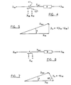
- Figure 4 shows a schematic diagram of a circuit branch of a phase-shifting interconnecting apparatus for injection of a voltage in quadrature;
- Figures 5 is a phase diagram showing voltage vectors involved in Figure 4;
- Figure 6 is a schematic diagram of a circuit branch of a phase-shifting interconnecting apparatus for injection of a voltage having a phase angle of 120°;
- Figures 7 is a phase diagram showing voltage vectors involved in Figure 6;
- Figure 8 is a circuit diagram showing a phase-shifting interconnecting apparatus for injection of voltages in quadrature using excitation transformer arrangements;
- Figure 9 is a phase diagram showing voltage vectors involved in Figure 8;
- Figure 10 is a circuit diagram showing a phase-shifting interconnecting apparatus for injection of voltages having phase angles of ±120° using excitation transformer arrangements;
- Figures 11 is a phase diagram showing voltage vectors involved in Figure 10;
- Figure 12 is a circuit diagram showing a phase-shifting interconnecting apparatus for independent injection of voltages in quadrature using excitation transformer arrangements;
- Figure 13 is a phase diagram showing voltage vectors involved in Figure 12;
- Figure 14 is a circuit diagram showing a phase-shifting interconnecting apparatus for injection of voltages in quadrature without excitation transformer arrangements;
- Figure 15 is a phase diagram showing voltage vectors involved in Figure 14;
- Figure 16 is a circuit diagram showing a phase-shifting interconnecting apparatus for injection of voltages having phase angles of ±120° without excitation transformer arrangements;
- Figure 17 is a phase diagram showing voltage vectors involved in Figure 16;
- Figure 18 is a circuit diagram showing a phase-shifting interconnecting apparatus for injection of a single voltage per interconnecting circuit branch;
- Figure 19 is a phase diagram showing voltage vectors involved in Figure 18;
- Figures 20 and 21 are schematic diagram of circuit branches of a phase-shifting interconnecting apparatus, for injection of a single voltage;
- Figure 22 is a circuit diagram showing a phase-shifting interconnecting apparatus having phase-shifting transformer arrangements in a squashed delta configuration;
- Figure 23 is a phase diagram showing voltage vectors involved in Figure 22;
- Figure 24 is a schematic diagram showing a power reversal switch circuit for the phase-shifting interconnecting apparatus shown in Figure 22;
- Figure 25 is a circuit diagram showing a phase-shifting interconnecting apparatus having phase-shifting transformer arrangements in a Mersereau configuration;
- Figure 26 is a phase diagram showing voltage vectors involved in Figure 25;
- Figures 27, 28 and 29 are phase diagrams showing voltage vectors relative to 3 modes of operation of a phase-shifting interconnecting apparatus for hexaphase AC networks;
- Figure 30 is a schematic diagram showing a phase-shifting interconnecting apparatus for hexaphase AC networks;
- Figure 31 is a circuit diagram showing series transformer arrangements for the phase-shifting interconnecting apparatus shown in Figure 30;
- Figure 32 is a circuit diagram showing excitation transformer arrangements for the phase-shifting interconnecting apparatus shown in Figure 30;
- Figure 33 is a circuit diagram showing a mode selecting switch circuit for the phase-shifting interconnecting apparatus shown in Figure 30;
- Figure 34 is a table showing characteristics for each mode of operation of the phase-shifting interconnecting apparatus shown in Figure 30;
- Figure 35 is a circuit diagram showing a phase-shifting interconnecting apparatus having phase-shifting transformer arrangements in a squashed delta configuration for hexaphase networks; and
- Figures 36, 37 and 38 are schematic diagrams of circuit branches of a phase-shifting interconnecting apparatus, having susceptances divided in two equal parts.
- In the following description and in the drawings, like reference characters designate like or corresponding parts throughout the several views.
- Referring to Figure 1, there is shown a schematic diagram illustrating the principle on which prior art interconnecting apparatus work for controlling power conditions between a first three-phase AC network S (for Source) and a second three-phase AC network R (for Receiver). The phase-shifted voltages applied to susceptances B1, B2..., Bn (value which is normally equivalent to the imaginary part of the admittance but which takes here a broader meaning by designating a group of reactive elements which can be represented by a single capacitor or a single inductor in a schematic circuit diagram) of the interconnecting apparatus are produced by adequate phase transposition device and/or transformer with Y, Δ and/or zigzag (ZZ) -connected windings, as depicted by
box 2. In such interconnecting apparatus, the whole power, as represented by arrow P, transferred from the AC network S to the AC network R flows throughout the phase transposition device and/ortransformer 2 which must be dimensioned for this purpose. - Referring to Figures 2 and 3, the method according to the present invention involves phase-shifting mechanisms for producing phase-shifts ψ, required by the susceptances B1, B2..., Bn. More particularly, the method consists in adding to a voltage V S derived for example from the AC network S a relatively small voltage V Q preferably in quadrature to obtain a resulting voltage V S1 having a modulus approximately equal to the modulus of the voltage V S but with a different phase.
- In practice, the small voltage V Q is generated by inducing in a primary winding 4 of a relatively small transformer 6 a phase-shifted fraction of a phase voltage of the AC network S. The primary winding 4 is connected in series with the considered susceptance B1, B2..., Bn. The voltage V S1 upstream (on the side of the AC network S with respect to a susceptance) from the susceptance B1, B2..., Bn results therefore from a vectorial addition of the phase voltage V S and the voltage V Q in the primary winding 4, and exhibits phase-shift characteristics as shown in Figure 2. Since an interconnecting apparatus normally comprises several susceptances B1, B2..., Bn (of capacitive and inductive types) to which are applied as many voltages from different phases, it is possible to use several primary windings 4 to produce the desired voltages (the primary windings 4 are generally associated with different phases).
- Advantage of such a topography lies in appreciable size reduction of the
transformer 6 and its MVA ratings since only a fraction P' of the power P transferred by the interconnecting apparatus flows in thetransformer 6. This advantage prevails especially for small angles of phase shifts ψ. Another advantage lies in the fact that the available angles of phase shifts ψ are not limited to multiple of 30°. Indeed, the modulus of the small voltage vector V Q can be modified by varying slightly the transformer ratios, changing thereby the phase-shifting effects. A continuum of angles of phase shifts ψ is therefore available. - Referring to Figures 4, 5, 6 and 7, it must be understood that the small voltage V Q must not necessarily be at 90° (in quadrature) from the phase voltage V S. Although the maximum efficiency is obtained with angle of voltage injection (addition of a small voltage to the phase voltage of a three-phase AC network for producing a new voltage generally having a similar modulus but with a different phase) substantially equal to 90°, it is possible for practical reasons that another angle is more appropriate. The case at 120° worth mentioning since it can be easily obtained from the voltage of another phase in a three-phase system. The injection at 120° has the advantage to limit the modulus increase of the voltage V S1 when operating with large values of ψ. The injection at 90° is for its part obtained from the line-line voltage of two other phases (as V SB, V SC).
- The fact to add a small voltage V Q in quadrature or at any other angle, in addition to the phase shift ψ, produces a small modification of the downstream (on the side of the AC network R with respect to a susceptance) voltage. The voltage V S1 has a modulus different from the voltage V S. In a classical phase-shifting device, such a difference in the modulus of the upstream and downstream voltages generates an undesirable current flow if the difference does not meet exactly the needs of the network. Indeed, when the phase-shifting device interconnects two powerful networks, only its low leakage impedance limits this current flow. In the same way, an inadequate adjustment of the phase shifts ψ produces such a current flow.
- Thus, for limiting this current, a classical phase-shifting device must continuously react to angular variations and even to variations of modulus. In some cases, a phase-shifting device having two degrees of freedom (modulus and angle) is required to carry out this task.
- In the case of interconnecting apparatus, susceptances are inserted in series with the phase-shifting device. Their properties are to act as buffers to the voltage, modulus and angle variations of the AC network, and make the transfer of active and reactive power much less sensible to these variations. Similarly, a small difference of modulus between V S and V S1 has almost no influence on the power transfer and can be therefore neglected, although its effects can be completely compensated by readjusting somewhat the values of the susceptances during design.
- In a general context of the present invention, the method of phase-shifting a voltage (e.g. V SA1) applied to at least one susceptance B interconnecting a phase line of a first polyphase AC network S with a corresponding phase line of a second polyphase AC network R, both AC networks being synchronous, comprises the steps of:
- connecting at least a portion of a primary winding 17 of a transformer in series with the susceptance B;
- deriving from the AC networks, an excitation voltage (e.g. V SB-V SC) having a phase shifted with respect to a phase voltage (e.g. V SA) provided by the phase line of the first AC network S; and
- applying the excitation voltage to at least a portion of a secondary winding 19 of the transformer, whereby the excitation voltage combines through the transformer with the phase voltage to cause phase-shifting of the voltage applied to the susceptance B.
- The method may comprise the additional step of changing an angle of phase-shifting produced by the transformer. This can be carried out for example either by adjusting the portion of the primary winding connected in series with the susceptance, or by modulating an amplitude of the excitation voltage, for changing the phase-shifting.
- The way by which the method is applied will become more apparent in view of several preferred embodiments of phase-shifting interconnecting apparatus described hereinafter.
- The excitation voltages can have for example phase angles of ±90° or ±120° with respect to the phase voltage V SA by selecting the appropriate manner to use the phase voltages provided by the AC networks. Various other phase angles are also available by means of these phase voltages or other voltages derived thereof.
- The phase-shifting interconnecting apparatus can take various topologies as shown in the Figures, which are all just as well advantageous depending on the operating conditions of the AC networks S and R and the desired power transfers therebetween.
- In a general context, the phase-shifting interconnecting apparatus interconnects respective phase lines (e.g. phases A-A, B-B, etc.) of first and second synchronous polyphase AC networks S, R. The apparatus comprises, for each pair of respective phase lines subjected to an interconnection, a pair of circuit branches in parallel, having first and second
common branch points capacitive susceptances susceptances susceptances susceptance - The phase-shifting interconnecting apparatus can further comprises mechanisms for changing angles of phase-shifting produced by the series transformer arrangements. As shown in Figure 22, these mechanisms may be obtained by means of
tap changers 78 associated with theprimary windings susceptances excitation transformer arrangements 18 for modulating each excitation voltage. Theexcitation transformer arrangements 18 haveprimary windings 20 for receiving respectively the phase voltages of the first AC network S, andsecondary windings 22 provided with tap changers orratio adjusters 24, for producing respectively adjustable voltages in phase with the phase voltages of the first AC network S. Each excitation voltage is derived from at least a corresponding one of the adjustable voltages. The phase-shift effects are thus adjustable by modulating amplitude of the adjustable voltages by means of the tap changers orratio adjusters 24. - Referring to Figure 8, there is shown a first embodiment of a phase-shifting interconnecting apparatus, for interconnecting three-phase AC networks, including first and second three-phase transformers providing respectively the
series transformer arrangements 16 and theexcitation transformer arrangements 18. The first three-phase transformer has three pairs ofprimary windings secondary windings primary windings secondary windings voltage tap changers 24. Each of theprimary windings secondary windings secondary windings - The use of the
excitation transformer arrangements 18 allows modulation of the injected voltages by means of the tap changers 24 (or ratio adjusters or any other suitable devices). The phase shifts ψ and hence the power transfers of active and/or reactive power are thus variable. Inversion of the power flow PSR (to a power flow PRS) is achieved at low voltage by means of power reversal switches 26 connected between thesecondary windings secondary windings phase transformer 18, for switching between two winding terminal connections of eachsecondary windings tap changers 24, the signs of the phase shifts ψ, are thereby changed. - The turns ratios (nSE1, nSE2) of the
primary windings capacitive susceptances primary windings , , ▲.
, ▲.
- Referring to Figure 9, there is shown a phase diagram of upstream and downstream voltages V SA, V RA (phase voltages), phase-shifted voltages V SA1, V SA2 and susceptance voltages V LA, V CA for phase A of the phase-shifting interconnecting apparatus shown in Figure 8 where the phase voltages V SA, V RA are in phase.
- Referring to Figure 10, there is shown a second embodiment of a phase-shifting interconnecting apparatus, similar to the first embodiment with the few exception that the injection is carried out at 60° instead of in quadrature. The difference is in the manner to connect the
series transformer arrangements 16. The turns ratios (nSE1, nSE2) of theprimary windings 17 should be in that case revised to adapt the new excitation voltage obtained with this topography and the values of thesusceptances - In this second embodiment, the first three-phase transformer providing the
series transformer arrangements 16 has three pairs ofprimary windings secondary windings excitation transformer arrangements 18 has threeprimary windings secondary windings tap changers 24. Each of theprimary windings secondary windings secondary windings - Referring to Figure 12, there is shown a third embodiment of a phase-shifting interconnecting apparatus, also similar to the first embodiment with the difference that the phase shifts ψ for the inductive and
capacitive inductances series transformer arrangement 16, each having threeprimary windings secondary windings excitation transformer arrangements 18, having threeprimary windings secondary windings tap changers 24. Each of theprimary windings secondary windings secondary windings - Referring to Figure 14, there is shown a fourth embodiment of a phase-shifting interconnecting apparatus, which has no excitation transformer arrangement, and which exhibits the phase-shifting features as shown in Figure 15. This topography is based on the fact that the phase-shifting interconnecting apparatus does not require precise adjustment of its
series transformer arrangements 16. In a case where various operating points are not needed by the expedient of the phase shifts ψ, the excitation transformer arrangements 18 (as shown in Figure 8) can be removed since theirtap changers 24 become useless. The secondary windings of theseries transformer arrangements 16 can then be directly powered from the upstream voltages V SA, V SB, V SC (phase voltages) of the first AC network S, saving thus as many MVA of transformation. With the exception of absence of excitation transformer arrangements and a relocation of the power reversal switches 26, this topology of the phase-shifting interconnecting apparatus also resembles the first embodiment. If a row of power operating points is nevertheless desired, it remains still possible to provide groups of discrete susceptances selectable by means of suitable switches (not shown) as in the case of classical interconnecting apparatus. - The three-phase transformer providing the series transformer arrangements has three pairs of
primary windings secondary windings first branch points 8 are connected to a corresponding interconnecting point of the Δ-connectedsecondary windings primary windings 17 and thesusceptances susceptances primary windings 17. - Referring to Figure 16, there is shown a fifth embodiment of a phase-shifting interconnecting apparatus, which also has no excitation transformer arrangement, and which exhibits the phase-shifting features as shown in Figure 17. Hence, this topography combines the properties and characteristics of the phase-shift interconnecting apparatus shown in Figures 10 and 14.
- The three-phase transformer providing the
series transformer arrangements 18 has three pairs ofprimary windings secondary windings first branch points 8 are connected to a corresponding one of the ground-connectedsecondary windings - Referring to Figure 18, there is shown a sixth embodiment of a phase-shift interphase power controller, which also has no excitation transformer arrangement, and which exhibits the phase-shifting features as shown in
- Figure 19. Hence, this topography resembles the embodiment of Figure 16, with the difference that only one phase-shifting is produced for only one of the two
susceptances - Referring to Figures 20 and 21, there are shown schematic diagrams of circuit branches of a phase-shifting interconnecting apparatus, for phase-shifting a single voltage applied either on the inductive or capacitive susceptance. The three-phase power transferred by the apparatus of Figure 20 is given by:


- For the apparatus of Figure 21, the three-phase power transferred is given by:


- For a power circulation from left to right, ψ1 < 0 < ψ2. The power, voltage and susceptance values are respectively in watts, volts and Siemens. VS and VR represent respectively the phase-ground voltages of the AC networks S and R.
- Referring to Figure 22, there is shown another embodiment of a phase-shifting interconnecting apparatus having phase-shifting transformer arrangements in a squashed delta configuration. This configuration matches advantageously the network characteristics and provides the phase-shifting features shown by the phase diagram in Figure 23, which are given by:

- All of the series transformer arrangements are provided by a three-phase transformer having three
primary windings secondary windings primary windings tap terminal 78 connected to a corresponding one of thesusceptances secondary windings first branch points 8 and one of thetap terminals 78. - Referring to Figure 24, there is shown a power reversal switch circuit specially adapted for the phase-shifting interconnecting apparatus shown in Figure 22. The switch circuit simply interchanges the series connections of the
primary windings - Referring to Figure 25, there is shown a phase-shifting interconnecting apparatus having phase-shifting transformer arrangements in a Mersereau configuration. All of the
series transformer arrangements 16 are provided by a first three-phase transformer having threeprimary windings secondary windings excitation transformer arrangements 18 are provided by a second three-phase transformer having threeprimary windings secondary windings tap changers 24. Each of theprimary windings tap terminal 25. Each of theprimary windings tap terminals 25. Each of thesecondary windings secondary windings series transformer arrangements 16 and theprimary windings excitation transformer arrangements 18 is given by:
- Referring to Figures 27, 28 and 29, there are shown phase diagrams of voltage vectors relative to 3 modes of operation of a phase-shifting interconnecting apparatus for hexaphase AC networks, namely a "M30" mode where V SA has a phase angle around -30° with respect to V RA, a "Centered" mode where V SA has a phase angle around 0° with respect to V RA, and a "P30" mode where V SA has a phase angle around +30° with respect to V RA.
- Referring to Figure 30, there is shown an embodiment of a phase-shifting interconnecting apparatus for hexaphase AC networks. The principles involved in phase-shifting the voltages applied to the
susceptances primary windings secondary windings 92, 94, 96, and 98, 100, 102. All of the excitation transformer arrangements F.32 are provided by third and fourth three-phase transformers both having threeprimary windings secondary windings tap changers primary windings secondary windings secondary windings 92, 94, 96, and 98, 100, 102. - The three modes of operation of the apparatus are selected by means of a mode selecting switch circuit connected between the series transformer arrangements F.31 and the
susceptances other switches 132 connected between the series transformer arrangements F.31 and the excitation transformer arrangements F.32. The characteristics pertaining to each mode of operation are reported in a table in Figure 34, for a phase A of the hexaphase AC networks. The characteristics for the other phases are obtained by replacing the subscripts by the cyclic permutation A → B → C → D → E → F → A. - Figure 35 shows another embodiment of a phase-shifting interconnecting apparatus for hexaphase AC networks, having
series transformer arrangements 16 in a squashed delta configuration. All of the series transformer means are provided by first and second three-phase transformers both having threeprimary windings secondary windings primary windings tap terminal 158 connected to a corresponding one of thesusceptances secondary windings first branch points 8 and one of thetap terminals 158. - Referring to Figures 36, 37 and 38, the susceptances of the phase-shifting interconnecting apparatus can be divided in two equal parts for protecting the phase-shifting device(s) against high fault currents. The power characteristics of the interconnecting apparatus remain the same.
- Although the present invention has been explained hereinafter by way of preferred embodiments thereof, it should be pointed out that any modifications to these preferred embodiments, within the scope of the appended claims, are not deemed to change or alter the nature and scope of the present invention.
Claims (20)
- A phase-shifting interconnecting apparatus for interconnecting respective phase lines of first and second synchronous polyphase AC networks (S, R), said apparatus comprising, for each pair of respective phase lines subjected to an interconnection, a pair of circuit branches in parallel including respectively inductive and capacitive susceptances (12, 14) subjected to proper phase shifted voltages,
each said pair of circuit branches having first and second common branch points (8, 10) provided with connecting means for connecting respectively said branch points (8, 10) to said respective phase lines;
said apparatus being characterised in that:
at least one of said susceptances (12,14) in each of said pairs of circuit branches is subjected to a voltage which is phase shifted using a series transformer means (16) including at least one primary winding (17) having at least a portion connected in series with said at least one of said susceptances (12, 14), and at least one secondary winding (19) having at least a portion adapted to receive an excitation voltage derived from said AC networks (S, R), said excitation voltage having a phase angle with respect to a phase voltage provided by one of said respective phase lines, whereby, in operation, said excitation voltage combines through said transformer means (16) with said phase voltage to cause phase-shifting of the voltage applied to said at least one of said susceptances (12, 14). - A phase-shifting interconnecting apparatus according to claim 1, characterised in that it further comprises:
means for changing an angle of phase-shifting produced by each said series transformer means (16). - A phase-shifting interconnecting apparatus according to claim 2, characterised in that said means for changing comprise a tap changer (78) associated with each said at least one primary winding (30, 32, 34), to adjust said at least a portion thereof connected in series with said at least one of said susceptances (12, 14).
- A phase-shifting interconnecting apparatus according to claim 2, characterised in that said means for changing comprise excitation transformer means (18) for modulating each said excitation voltage, said excitation transformer means (18) having primary windings (20) arranged respectively to receive phase voltages of said first AC network (S), and secondary windings (22) provided with tap changers or adjusters (24), for producing respectively adjustable voltages in phase with the phase voltages of the first AC network (S), each said excitation voltage being derived from at least a corresponding one of said adjustable voltages.
- A phase-shifting interconnecting apparatus according to claim 1 or 4, characterised in that each said series transformer means (16) has two primary windings (30, 32, 34) each having at least a portion connected in series with a corresponding one of said susceptances (12, 14).
- A phase-shifting interconnecting apparatus according to claim 1, characterised in that each said capacitive susceptance (14) comprises at least one capacitor, and each said inductive susceptance (12) comprises at least one inductor.
- A phase-shifting interconnecting apparatus according to claim 1, characterised in that it further comprises power reversal switch means (26) connected between said susceptances (12, 14) and said series transformer means (16), for providing a plurality of selectively opened or closed electrical paths therebetween.
- A phase-shifting interconnecting apparatus according to claim 4, characterised in that it further comprises power reversal switch means (26) connected between said series transformer means (16) and said excitation transformer means (18), for providing a plurality of selectively opened or closed electrical paths therebetween.
- A phase-shifting interconnecting apparatus according to claim 5, wherein both of said polyphase AC networks (S, R) are three-phase AC networks, said apparatus being characterised in that all of said series transformer means (16) are provided by a first three-phase transformer having three pairs of primary windings (30, 32, 34) magnetically coupled respectively with three Δ-connected secondary windings (36, 38, 40), and all of said excitation transformer means (18) are provided by a second three-phase transformer having three primary windings (42, 44, 46) magnetically coupled respectively with three secondary windings (48, 50, 52) with grounded tap changers (26), each of said primary windings (42, 44, 46) of the second three-phase transformer being connected between a ground and a corresponding one of said first branch points (8), each of said secondary windings (48, 50, 52) of the second three-phase transformer being connected to a corresponding interconnecting point of said Δ-connected secondary windings (36, 38, 40) of the first three-phase transformer.
- A phase-shifting interconnecting apparatus according to claim 5, wherein both of said polyphase AC networks (S, R) are three-phase AC networks, said apparatus being characterised in that all of said series transformer means (16) are provided by a first three-phase transformer having three pairs of primary windings (30, 32, 34) magnetically coupled respectively with three ground-connected secondary windings (36, 38, 40), and all of said excitation transformer means (18) are provided by a second three-phase transformer having three primary windings (42, 44, 46) magnetically coupled respectively with three secondary windings (48, 50, 52) with grounded tap changers (24), each of said primary windings (42, 44, 46) of the second three-phase transformer being connected between a ground and a corresponding one of said first branch points (8), each of said secondary windings (48, 50, 52) of the second three-phase transformer being connected to a corresponding one of said ground-connected secondary windings (36, 38, 40) of the first three-phase transformer.
- A phase-shifting interconnecting apparatus according to claim 4, wherein both of said polyphase AC networks (S, R) are three-phase AC networks, said apparatus being characterised in that all of said series transformer means (16) are provided by first and second three-phase transformers each having three primary windings (54, 56, 58) magnetically coupled respectively with three Δ-connected secondary windings (60, 62, 64), and all of said excitation transformer means (18) are provided by a third three-phase transformer having three primary windings (66, 68, 70) magnetically coupled respectively with three pairs of secondary windings (72, 74, 76) with grounded tap changers (24), each of said primary windings (66, 68, 70) of the third three-phase transformer being connected between a ground and a corresponding one of said first branch points (8), each of said pairs of said secondary windings (72, 74, 76) of the third three-phase transformer being Δ-connected to corresponding interconnecting points of said connected secondary windings (60, 62, 64) of the first and second three-phase transformer respectively, said first three-phase transformer being coupled with said inductive susceptances (12) while said second three-phase transformer being coupled with said capacitive susceptances (14).
- A phase-shifting interconnecting apparatus according to claim 5, wherein both polyphase AC networks (S, R) are three-phase AC networks, said apparatus being characterised in that all of said series transformer means (16) are provided by a three-phase transformer having three pairs of primary windings (30, 32, 34) magnetically coupled respectively with three Δ-connected secondary windings (36, 38, 40), each of said first branch points (8) being connected to a corresponding interconnecting point of said Δ-connected secondary windings (36, 38, 40) of the three-phase transformer.
- A phase-shifting interconnecting apparatus according to claim 5, wherein both polyphase AC networks (S, R) are three-phase AC networks, said apparatus being characterised in that all of said series transformer means (16) are provided by a three-phase transformer having three pairs of primary windings (30, 32, 34) magnetically coupled respectively with three ground-connected secondary windings (36, 38, 40), each of said first branch points (8) being connected to a corresponding one of said ground-connected secondary windings (36, 38, 40) of the three-phase transformer.
- A phase-shifting interconnecting apparatus according to claim 1, wherein both polyphase AC networks (S, R) are three-phase AC networks, said apparatus being characterised in that all of said series transformer means are provided by a three-phase transformer having three primary windings (30, 32, 34) magnetically coupled respectively with three ground-connected secondary windings (36, 38, 40), each of said first branch points (8) being connected to a corresponding one of said ground-connected secondary windings (36, 38, 40) of the three-phase transformer.
- A phase-shifting interconnecting apparatus according to claim 1, wherein both polyphase AC networks (S, R) are three-phase AC networks, said apparatus being characterised in that all of said series transformer means (16) are provided by a three-phase transformer having three primary windings (30, 32, 34) magnetically coupled respectively with three secondary windings (36, 38, 40), each of said primary windings (30, 32, 34) being provided with a tap terminal (78) connected to a corresponding one of said susceptances (12, 14), each of said secondary windings (36, 38, 40) being connected between a corresponding one of said first branch points (8) and one of said tap terminals (78).
- A phase-shifting interconnecting apparatus according to claim 1, wherein both polyphase AC networks (S, R) are three-phase AC networks, said apparatus being characterised in that all of said series transformer means (16) are provided by a first three-phase transformer having three primary windings (30, 32, 34) magnetically coupled respectively with three Δ-connected secondary windings (36, 38, 40), and all of said excitation transformer means (18) are provided by a second three-phase transformer having three primary windings (42, 44, 46) magnetically coupled respectively with three secondary windings (48, 50, 52) with grounded tap changers (24), each of said primary windings (30, 32, 34) of the first three-phase transformer being provided with a tap terminal (25), each of said primary windings (42, 44, 46) of the second three-phase transformer being connected between a ground and a corresponding one of said tap terminals (25), each of said secondary windings (48, 50, 52) of the second three-phase transformer being connected to a corresponding interconnecting point of said Δ-connected secondary windings (36, 38, 40) of the first three-phase transformer.
- A phase-shifting interconnecting apparatus according to claim 5, wherein said polyphase AC networks (S, R) are hexaphase AC networks, said apparatus being characterised in that all of said series transformer means (16) are provided by first and second three-phase transformers both having three pairs of primary windings (80, 82, 84 and 86, 88, 90) magnetically coupled respectively with three Δ-connected secondary windings (92, 94, 96 and 98, 100, 102), and all of said excitation transformer means (18) are provided by third and fourth three-phase transformers both having three primary windings (104, 106, 108 and 110, 112, 114) magnetically coupled respectively with three secondary windings (116, 118, 120 and 122, 124, 126) with grounded tap changers (128, 130), each of said primary windings (104, 106, 108 and 110, 112, 114) of the third and fourth three-phase transformers being connected between a ground and a corresponding one of said first branch points (8), each of said secondary windings (116, 118, 120 and 122, 124, 126) of the third and fourth three-phase transformers being connected to a corresponding interconnecting point of said Δ-connected secondary windings (92, 94, 96 and 98, 100, 102).
- A phase-shifting interconnecting apparatus according to claim 17, characterised in that it further comprises mode switch means connected between said susceptances (12, 14) and said series transformer means (16), for providing a plurality of selectively opened or closed electrical paths therebetween.
- A phase-shifting interconnecting apparatus according to claim 1, wherein said polyphase AC networks are hexaphase AC networks, said apparatus being characterised in that all of said series transformer means (16) are provided by first and second three-phase transformers both having three primary windings (134, 136, 138 and 140, 142, 144) magnetically coupled respectively with three secondary windings (146, 148, 150 and 152, 154, 156 ), each of said primary windings (134, 136, 138 and 140, 142, 144) being provided with a tap terminal (158) connected to a corresponding one of said susceptances (12, 14), each of said secondary windings (146, 148, 150 and 152, 154, 156) being connected between a corresponding one of said first branch points (8) and one of said tap terminals (158).
- A phase-shifting interconnecting apparatus according to claim 1, characterised in that said at least one of said susceptances (12, 14) is divided in two equal parts on both sides of said at least a portion of said at least one primary winding.
Applications Claiming Priority (3)
| Application Number | Priority Date | Filing Date | Title |
|---|---|---|---|
| US6151293A | 1993-05-14 | 1993-05-14 | |
| PCT/CA1994/000259 WO1994027351A1 (en) | 1993-05-14 | 1994-05-09 | Method of phase-shifting voltages applied to susceptances interconnecting two synchronous polyphase ac networks and a phase-shifting interconnecting apparatus thereof |
| US61512 | 2002-02-01 |
Publications (2)
| Publication Number | Publication Date |
|---|---|
| EP0698309A1 EP0698309A1 (en) | 1996-02-28 |
| EP0698309B1 true EP0698309B1 (en) | 1997-04-09 |
Family
ID=22036256
Family Applications (1)
| Application Number | Title | Priority Date | Filing Date |
|---|---|---|---|
| EP94915007A Expired - Lifetime EP0698309B1 (en) | 1993-05-14 | 1994-05-09 | Phase-shifting apparatus for interconnecting two synchronous polyphase ac networks |
Country Status (14)
| Country | Link |
|---|---|
| US (1) | US5619119A (en) |
| EP (1) | EP0698309B1 (en) |
| JP (1) | JPH08511152A (en) |
| KR (1) | KR0173717B1 (en) |
| CN (1) | CN1123066A (en) |
| AU (1) | AU676561B2 (en) |
| BR (1) | BR9406688A (en) |
| CA (1) | CA2161244C (en) |
| DE (1) | DE69402544T2 (en) |
| DK (1) | DK0698309T3 (en) |
| ES (1) | ES2103129T3 (en) |
| NO (1) | NO311156B1 (en) |
| NZ (1) | NZ265913A (en) |
| WO (1) | WO1994027351A1 (en) |
Cited By (1)
| Publication number | Priority date | Publication date | Assignee | Title |
|---|---|---|---|---|
| US10742028B2 (en) | 2017-04-21 | 2020-08-11 | Abb Power Grids Switzerland Ag | Longitudinal voltage regulation at the line terminals of a phase shifting transformer |
Families Citing this family (16)
| Publication number | Priority date | Publication date | Assignee | Title |
|---|---|---|---|---|
| GB9422902D0 (en) * | 1994-11-14 | 1995-01-04 | Citeq | Methods of enhancing the transfer capacity of a transformer station and of power flow regulation using parallel arrangements of a phase-shifting transformer w |
| DE19612744C1 (en) * | 1996-03-29 | 1997-11-13 | Siemens Ag | Transformer arrangement |
| US6011368A (en) * | 1999-03-30 | 2000-01-04 | Dana Corporation | Sensorless detection of a locked rotor in a switched reluctance motor |
| US9605591B2 (en) * | 2000-10-09 | 2017-03-28 | Energy Transfer Group, L.L.C. | Arbitrage control system for two or more available power sources |
| US6636784B1 (en) | 2000-10-09 | 2003-10-21 | Energy Transfer Group, L.L.C. | Electricity transfer station |
| TWI285571B (en) * | 2004-12-15 | 2007-08-21 | Univ Nat Cheng Kung | Power conversion apparatus for pulse current |
| RU2393608C2 (en) * | 2006-03-28 | 2010-06-27 | Абб Рисёч Лтд | Device and method of power flow control in transmission line |
| US9634490B2 (en) * | 2011-02-08 | 2017-04-25 | General Electric Company | Dynamic voltage restoration system and method |
| CN102508132B (en) * | 2011-11-10 | 2013-07-17 | 保定天威集团有限公司 | Operation impact test method suitable for dual-core phase-shifting transformer |
| CN102801381B (en) * | 2012-08-15 | 2014-10-29 | 上海交通大学 | Controllable transformer device capable of controlling amplitude and phase angle of voltage individually and control method for same |
| WO2014053989A2 (en) | 2012-10-01 | 2014-04-10 | Abb Technology Ltd. | A method and a system for a fast bus transfer in an electrical power system |
| CN106053921B (en) * | 2016-08-02 | 2019-08-27 | 中国电力科学研究院 | Method for calculating stage voltage under load condition of symmetrical double-core phase-shifting transformer |
| PL3336650T3 (en) * | 2016-12-19 | 2023-07-03 | Hitachi Energy Switzerland Ag | Longitudinal voltage regulator |
| CN107492891B (en) * | 2017-08-25 | 2023-04-28 | 国网安徽省电力公司安庆供电公司 | Mobile intelligent ring closure device and its usage method |
| RU195977U1 (en) * | 2019-11-06 | 2020-02-12 | Публичное акционерное общество энергетики и электрификации «Сахалинэнерго» | Transformer for melting ice on air lines |
| SI26436A (en) * | 2022-11-24 | 2024-05-31 | Grid Instruments D.O.O. | Phase balancing device for a polyphase electric power distribution network |
Citations (1)
| Publication number | Priority date | Publication date | Assignee | Title |
|---|---|---|---|---|
| US4621198A (en) * | 1983-06-14 | 1986-11-04 | Hydro-Quebec | Method and system for interconnecting two synchronous or asynchronous electrical alternating three-phase networks by means of variable reactive impedances |
Family Cites Families (8)
| Publication number | Priority date | Publication date | Assignee | Title |
|---|---|---|---|---|
| GB394934A (en) * | 1933-03-07 | 1933-07-06 | Gen Electric | Improvements in means for regulating by transformers the distribution of wattless and load currents in ring mains |
| JPS4731541B1 (en) * | 1968-08-14 | 1972-08-14 | ||
| US4156174A (en) * | 1977-12-30 | 1979-05-22 | Westinghouse Electric Corp. | Phase-angle regulator |
| EP0152002B1 (en) * | 1984-02-10 | 1988-11-17 | BBC Brown Boveri AG | Phase-shifter |
| DE3624854A1 (en) * | 1986-07-23 | 1988-01-28 | Thomson Brandt Gmbh | CIRCUIT ARRANGEMENT FOR SHIFTING THE PHASE OF A SIGNAL |
| CA1292512C (en) * | 1988-08-04 | 1991-11-26 | Hydro-Quebec | Method and system for quadrature interconnection of two synchronous or asynchronous three-phase networks |
| US5124904A (en) * | 1990-08-17 | 1992-06-23 | Westinghouse Electric Corp. | Optimized 18-pulse type AC/DC, or DC/AC, converter system |
| US5461300A (en) * | 1993-03-30 | 1995-10-24 | Electric Power Research Institute, Inc. | Phase angle regulating transformer with a single core per phase |
-
1994
- 1994-05-09 WO PCT/CA1994/000259 patent/WO1994027351A1/en not_active Ceased
- 1994-05-09 DE DE69402544T patent/DE69402544T2/en not_active Expired - Fee Related
- 1994-05-09 BR BR9406688A patent/BR9406688A/en not_active IP Right Cessation
- 1994-05-09 NZ NZ265913A patent/NZ265913A/en unknown
- 1994-05-09 DK DK94915007.2T patent/DK0698309T3/en active
- 1994-05-09 CN CN94192091A patent/CN1123066A/en active Pending
- 1994-05-09 EP EP94915007A patent/EP0698309B1/en not_active Expired - Lifetime
- 1994-05-09 JP JP6524764A patent/JPH08511152A/en active Pending
- 1994-05-09 AU AU66435/94A patent/AU676561B2/en not_active Ceased
- 1994-05-09 CA CA002161244A patent/CA2161244C/en not_active Expired - Fee Related
- 1994-05-09 ES ES94915007T patent/ES2103129T3/en not_active Expired - Lifetime
- 1994-05-09 US US08/535,060 patent/US5619119A/en not_active Expired - Fee Related
- 1994-05-09 KR KR1019950705065A patent/KR0173717B1/en not_active Expired - Fee Related
-
1995
- 1995-10-23 NO NO19954222A patent/NO311156B1/en unknown
Patent Citations (1)
| Publication number | Priority date | Publication date | Assignee | Title |
|---|---|---|---|---|
| US4621198A (en) * | 1983-06-14 | 1986-11-04 | Hydro-Quebec | Method and system for interconnecting two synchronous or asynchronous electrical alternating three-phase networks by means of variable reactive impedances |
Cited By (1)
| Publication number | Priority date | Publication date | Assignee | Title |
|---|---|---|---|---|
| US10742028B2 (en) | 2017-04-21 | 2020-08-11 | Abb Power Grids Switzerland Ag | Longitudinal voltage regulation at the line terminals of a phase shifting transformer |
Also Published As
| Publication number | Publication date |
|---|---|
| NO954222D0 (en) | 1995-10-23 |
| US5619119A (en) | 1997-04-08 |
| CN1123066A (en) | 1996-05-22 |
| AU6643594A (en) | 1994-12-12 |
| JPH08511152A (en) | 1996-11-19 |
| NO954222L (en) | 1995-10-23 |
| CA2161244A1 (en) | 1994-11-24 |
| DE69402544D1 (en) | 1997-05-15 |
| EP0698309A1 (en) | 1996-02-28 |
| NO311156B1 (en) | 2001-10-15 |
| ES2103129T3 (en) | 1997-08-16 |
| DK0698309T3 (en) | 1997-08-25 |
| KR960702691A (en) | 1996-04-27 |
| NZ265913A (en) | 1996-09-25 |
| BR9406688A (en) | 1996-02-06 |
| DE69402544T2 (en) | 1997-12-04 |
| KR0173717B1 (en) | 1999-05-01 |
| AU676561B2 (en) | 1997-03-13 |
| WO1994027351A1 (en) | 1994-11-24 |
| CA2161244C (en) | 1999-01-12 |
Similar Documents
| Publication | Publication Date | Title |
|---|---|---|
| US5619119A (en) | Method of phase-shifting voltages applied to susceptances interconnecting two synchronous polyphase AC networks and a phase-shifting interconnecting apparatus thereof | |
| CN100474730C (en) | A device and a method for control of power flow in a transmission line | |
| EP0801833B1 (en) | Transmission line power flow controller with unequal advancement and retardation of transmission angle | |
| US5515264A (en) | Optimized high power voltage sourced inverter system | |
| US5461300A (en) | Phase angle regulating transformer with a single core per phase | |
| US6335613B1 (en) | Versatile power flow transformers for compensating power flow in a transmission line | |
| CN101416365B (en) | Apparatus and method for controlling electric power tide in transmission line | |
| GB2285523A (en) | Multilevel converter for connection to AC system | |
| US6841976B1 (en) | Multi-line power flow transformer for compensating power flow among transmission lines | |
| EP0792534B1 (en) | Methods of enhancing capacity of transformer equipment and of power flow control using phase-shifting transformers and series impedances in parallel arrangements | |
| CA2145958C (en) | Phase shifting transformer with low zero phase sequence impedance | |
| US4336488A (en) | Transformer for the controllable shifting of the phase angle of output voltages in relation to the phase angles of input voltages | |
| US6396248B1 (en) | Versatile power flow transformers for compensating power flow in a transmission line | |
| US6384581B1 (en) | Versatile power flow transformers for compensating power flow in a transmission line | |
| Uzunovic | EMTP, transient stability and power flow models and controls of VSC based FACTS controllers | |
| CN110366811A (en) | voltage source converter | |
| US6420856B1 (en) | Versatile power flow transformers for compensating power flow in a transmission line | |
| GB2307803A (en) | Static VAR compensator with capacitor energy dissipation | |
| CA1141819A (en) | Variable phase-shifting transformer network | |
| US4001670A (en) | Static reactive power generating apparatus | |
| US5731971A (en) | Apparatus for providing multiple, phase-shifted power outputs | |
| JP2001045663A (en) | Series compensator | |
| SU936211A1 (en) | Device for interconnection of two power systems | |
| SU1432704A1 (en) | Converter | |
| SU851357A1 (en) | Device for regulating three-phase voltage |
Legal Events
| Date | Code | Title | Description |
|---|---|---|---|
| PUAI | Public reference made under article 153(3) epc to a published international application that has entered the european phase |
Free format text: ORIGINAL CODE: 0009012 |
|
| 17P | Request for examination filed |
Effective date: 19951118 |
|
| AK | Designated contracting states |
Kind code of ref document: A1 Designated state(s): BE DE DK ES FR GB IE IT NL SE |
|
| GRAG | Despatch of communication of intention to grant |
Free format text: ORIGINAL CODE: EPIDOS AGRA |
|
| 17Q | First examination report despatched |
Effective date: 19960701 |
|
| GRAH | Despatch of communication of intention to grant a patent |
Free format text: ORIGINAL CODE: EPIDOS IGRA |
|
| GRAH | Despatch of communication of intention to grant a patent |
Free format text: ORIGINAL CODE: EPIDOS IGRA |
|
| GRAA | (expected) grant |
Free format text: ORIGINAL CODE: 0009210 |
|
| AK | Designated contracting states |
Kind code of ref document: B1 Designated state(s): BE DE DK ES FR GB IE IT NL SE |
|
| PG25 | Lapsed in a contracting state [announced via postgrant information from national office to epo] |
Ref country code: NL Effective date: 19970409 Ref country code: IT Free format text: LAPSE BECAUSE OF FAILURE TO SUBMIT A TRANSLATION OF THE DESCRIPTION OR TO PAY THE FEE WITHIN THE PRE;WARNING: LAPSES OF ITALIAN PATENTS WITH EFFECTIVE DATE BEFORE 2007 MAY HAVE OCCURRED AT ANY TIME BEFORE 2007. THE CORRECT EFFECTIVE DATE MAY BE DIFFERENT FROM THE ONE RECORDED.SCRIBED TIME-LIMIT Effective date: 19970409 |
|
| ET | Fr: translation filed | ||
| REF | Corresponds to: |
Ref document number: 69402544 Country of ref document: DE Date of ref document: 19970515 |
|
| PG25 | Lapsed in a contracting state [announced via postgrant information from national office to epo] |
Ref country code: IE Free format text: LAPSE BECAUSE OF NON-PAYMENT OF DUE FEES Effective date: 19970609 |
|
| REG | Reference to a national code |
Ref country code: IE Ref legal event code: FG4D Free format text: 73178 |
|
| REG | Reference to a national code |
Ref country code: ES Ref legal event code: FG2A Ref document number: 2103129 Country of ref document: ES Kind code of ref document: T3 |
|
| REG | Reference to a national code |
Ref country code: DK Ref legal event code: T3 |
|
| NLV1 | Nl: lapsed or annulled due to failure to fulfill the requirements of art. 29p and 29m of the patents act | ||
| PLBE | No opposition filed within time limit |
Free format text: ORIGINAL CODE: 0009261 |
|
| STAA | Information on the status of an ep patent application or granted ep patent |
Free format text: STATUS: NO OPPOSITION FILED WITHIN TIME LIMIT |
|
| 26N | No opposition filed | ||
| REG | Reference to a national code |
Ref country code: GB Ref legal event code: IF02 |
|
| PGFP | Annual fee paid to national office [announced via postgrant information from national office to epo] |
Ref country code: SE Payment date: 20050425 Year of fee payment: 12 |
|
| PGFP | Annual fee paid to national office [announced via postgrant information from national office to epo] |
Ref country code: BE Payment date: 20050426 Year of fee payment: 12 |
|
| PGFP | Annual fee paid to national office [announced via postgrant information from national office to epo] |
Ref country code: GB Payment date: 20050427 Year of fee payment: 12 Ref country code: DK Payment date: 20050427 Year of fee payment: 12 |
|
| PGFP | Annual fee paid to national office [announced via postgrant information from national office to epo] |
Ref country code: DE Payment date: 20050502 Year of fee payment: 12 |
|
| PGFP | Annual fee paid to national office [announced via postgrant information from national office to epo] |
Ref country code: ES Payment date: 20050510 Year of fee payment: 12 |
|
| PGFP | Annual fee paid to national office [announced via postgrant information from national office to epo] |
Ref country code: FR Payment date: 20050530 Year of fee payment: 12 |
|
| PG25 | Lapsed in a contracting state [announced via postgrant information from national office to epo] |
Ref country code: GB Free format text: LAPSE BECAUSE OF NON-PAYMENT OF DUE FEES Effective date: 20060509 |
|
| PG25 | Lapsed in a contracting state [announced via postgrant information from national office to epo] |
Ref country code: SE Free format text: LAPSE BECAUSE OF NON-PAYMENT OF DUE FEES Effective date: 20060510 Ref country code: ES Free format text: LAPSE BECAUSE OF NON-PAYMENT OF DUE FEES Effective date: 20060510 |
|
| PG25 | Lapsed in a contracting state [announced via postgrant information from national office to epo] |
Ref country code: DK Free format text: LAPSE BECAUSE OF NON-PAYMENT OF DUE FEES Effective date: 20060531 Ref country code: BE Free format text: LAPSE BECAUSE OF NON-PAYMENT OF DUE FEES Effective date: 20060531 |
|
| PG25 | Lapsed in a contracting state [announced via postgrant information from national office to epo] |
Ref country code: DE Free format text: LAPSE BECAUSE OF NON-PAYMENT OF DUE FEES Effective date: 20061201 |
|
| REG | Reference to a national code |
Ref country code: DK Ref legal event code: EBP |
|
| EUG | Se: european patent has lapsed | ||
| GBPC | Gb: european patent ceased through non-payment of renewal fee |
Effective date: 20060509 |
|
| REG | Reference to a national code |
Ref country code: FR Ref legal event code: ST Effective date: 20070131 |
|
| REG | Reference to a national code |
Ref country code: ES Ref legal event code: FD2A Effective date: 20060510 |
|
| BERE | Be: lapsed |
Owner name: *CITEQ Effective date: 20060531 |
|
| PG25 | Lapsed in a contracting state [announced via postgrant information from national office to epo] |
Ref country code: FR Free format text: LAPSE BECAUSE OF NON-PAYMENT OF DUE FEES Effective date: 20060531 |