EP0696478A1 - Pump - Google Patents
Pump Download PDFInfo
- Publication number
- EP0696478A1 EP0696478A1 EP94112408A EP94112408A EP0696478A1 EP 0696478 A1 EP0696478 A1 EP 0696478A1 EP 94112408 A EP94112408 A EP 94112408A EP 94112408 A EP94112408 A EP 94112408A EP 0696478 A1 EP0696478 A1 EP 0696478A1
- Authority
- EP
- European Patent Office
- Prior art keywords
- valve
- pump chamber
- pump
- suction
- valve body
- Prior art date
- Legal status (The legal status is an assumption and is not a legal conclusion. Google has not performed a legal analysis and makes no representation as to the accuracy of the status listed.)
- Withdrawn
Links
- 239000012530 fluid Substances 0.000 claims abstract description 123
- 230000005484 gravity Effects 0.000 claims description 7
- 239000011347 resin Substances 0.000 claims description 6
- 229920005989 resin Polymers 0.000 claims description 6
- 230000004044 response Effects 0.000 claims description 4
- 230000000903 blocking effect Effects 0.000 claims description 3
- 239000000463 material Substances 0.000 claims description 3
- 230000001105 regulatory effect Effects 0.000 claims description 3
- 238000005728 strengthening Methods 0.000 claims 2
- 230000006835 compression Effects 0.000 claims 1
- 238000007906 compression Methods 0.000 claims 1
- 230000001276 controlling effect Effects 0.000 claims 1
- 238000005086 pumping Methods 0.000 abstract description 6
- 239000002453 shampoo Substances 0.000 abstract description 3
- 230000007423 decrease Effects 0.000 description 5
- 238000007789 sealing Methods 0.000 description 4
- 239000002699 waste material Substances 0.000 description 3
- 238000009825 accumulation Methods 0.000 description 2
- 239000007788 liquid Substances 0.000 description 2
- 230000007246 mechanism Effects 0.000 description 2
- 239000000203 mixture Substances 0.000 description 2
- 244000273618 Sphenoclea zeylanica Species 0.000 description 1
- 229910000831 Steel Inorganic materials 0.000 description 1
- 230000009471 action Effects 0.000 description 1
- 230000001174 ascending effect Effects 0.000 description 1
- 230000002349 favourable effect Effects 0.000 description 1
- 239000011346 highly viscous material Substances 0.000 description 1
- 230000004941 influx Effects 0.000 description 1
- 230000000977 initiatory effect Effects 0.000 description 1
- 230000002452 interceptive effect Effects 0.000 description 1
- 239000002184 metal Substances 0.000 description 1
- 238000000034 method Methods 0.000 description 1
- 230000004048 modification Effects 0.000 description 1
- 238000012986 modification Methods 0.000 description 1
- 238000002360 preparation method Methods 0.000 description 1
- 230000008569 process Effects 0.000 description 1
- 230000002250 progressing effect Effects 0.000 description 1
- 239000011342 resin composition Substances 0.000 description 1
- 230000035945 sensitivity Effects 0.000 description 1
- 238000010008 shearing Methods 0.000 description 1
- 239000000344 soap Substances 0.000 description 1
- 239000007921 spray Substances 0.000 description 1
- 239000010959 steel Substances 0.000 description 1
Images




Classifications
-
- B—PERFORMING OPERATIONS; TRANSPORTING
- B05—SPRAYING OR ATOMISING IN GENERAL; APPLYING FLUENT MATERIALS TO SURFACES, IN GENERAL
- B05B—SPRAYING APPARATUS; ATOMISING APPARATUS; NOZZLES
- B05B11/00—Single-unit hand-held apparatus in which flow of contents is produced by the muscular force of the operator at the moment of use
- B05B11/0005—Components or details
-
- B—PERFORMING OPERATIONS; TRANSPORTING
- B05—SPRAYING OR ATOMISING IN GENERAL; APPLYING FLUENT MATERIALS TO SURFACES, IN GENERAL
- B05B—SPRAYING APPARATUS; ATOMISING APPARATUS; NOZZLES
- B05B11/00—Single-unit hand-held apparatus in which flow of contents is produced by the muscular force of the operator at the moment of use
- B05B11/01—Single-unit hand-held apparatus in which flow of contents is produced by the muscular force of the operator at the moment of use characterised by the means producing the flow
- B05B11/10—Pump arrangements for transferring the contents from the container to a pump chamber by a sucking effect and forcing the contents out through the dispensing nozzle
- B05B11/1001—Piston pumps
-
- B—PERFORMING OPERATIONS; TRANSPORTING
- B05—SPRAYING OR ATOMISING IN GENERAL; APPLYING FLUENT MATERIALS TO SURFACES, IN GENERAL
- B05B—SPRAYING APPARATUS; ATOMISING APPARATUS; NOZZLES
- B05B11/00—Single-unit hand-held apparatus in which flow of contents is produced by the muscular force of the operator at the moment of use
- B05B11/0005—Components or details
- B05B11/0062—Outlet valves actuated by the pressure of the fluid to be sprayed
-
- B—PERFORMING OPERATIONS; TRANSPORTING
- B05—SPRAYING OR ATOMISING IN GENERAL; APPLYING FLUENT MATERIALS TO SURFACES, IN GENERAL
- B05B—SPRAYING APPARATUS; ATOMISING APPARATUS; NOZZLES
- B05B11/00—Single-unit hand-held apparatus in which flow of contents is produced by the muscular force of the operator at the moment of use
- B05B11/01—Single-unit hand-held apparatus in which flow of contents is produced by the muscular force of the operator at the moment of use characterised by the means producing the flow
- B05B11/10—Pump arrangements for transferring the contents from the container to a pump chamber by a sucking effect and forcing the contents out through the dispensing nozzle
- B05B11/1042—Components or details
- B05B11/1043—Sealing or attachment arrangements between pump and container
- B05B11/1046—Sealing or attachment arrangements between pump and container the pump chamber being arranged substantially coaxially to the neck of the container
- B05B11/1047—Sealing or attachment arrangements between pump and container the pump chamber being arranged substantially coaxially to the neck of the container the pump being preassembled as an independent unit before being mounted on the container
-
- B—PERFORMING OPERATIONS; TRANSPORTING
- B05—SPRAYING OR ATOMISING IN GENERAL; APPLYING FLUENT MATERIALS TO SURFACES, IN GENERAL
- B05B—SPRAYING APPARATUS; ATOMISING APPARATUS; NOZZLES
- B05B11/00—Single-unit hand-held apparatus in which flow of contents is produced by the muscular force of the operator at the moment of use
- B05B11/01—Single-unit hand-held apparatus in which flow of contents is produced by the muscular force of the operator at the moment of use characterised by the means producing the flow
- B05B11/10—Pump arrangements for transferring the contents from the container to a pump chamber by a sucking effect and forcing the contents out through the dispensing nozzle
- B05B11/1042—Components or details
- B05B11/1059—Means for locking a pump or its actuation means in a fixed position
- B05B11/106—Means for locking a pump or its actuation means in a fixed position in a retracted position, e.g. in an end-of-dispensing-stroke position
-
- B—PERFORMING OPERATIONS; TRANSPORTING
- B05—SPRAYING OR ATOMISING IN GENERAL; APPLYING FLUENT MATERIALS TO SURFACES, IN GENERAL
- B05B—SPRAYING APPARATUS; ATOMISING APPARATUS; NOZZLES
- B05B11/00—Single-unit hand-held apparatus in which flow of contents is produced by the muscular force of the operator at the moment of use
- B05B11/01—Single-unit hand-held apparatus in which flow of contents is produced by the muscular force of the operator at the moment of use characterised by the means producing the flow
- B05B11/10—Pump arrangements for transferring the contents from the container to a pump chamber by a sucking effect and forcing the contents out through the dispensing nozzle
- B05B11/1042—Components or details
- B05B11/1066—Pump inlet valves
- B05B11/1067—Pump inlet valves actuated by pressure
-
- B—PERFORMING OPERATIONS; TRANSPORTING
- B05—SPRAYING OR ATOMISING IN GENERAL; APPLYING FLUENT MATERIALS TO SURFACES, IN GENERAL
- B05B—SPRAYING APPARATUS; ATOMISING APPARATUS; NOZZLES
- B05B11/00—Single-unit hand-held apparatus in which flow of contents is produced by the muscular force of the operator at the moment of use
- B05B11/01—Single-unit hand-held apparatus in which flow of contents is produced by the muscular force of the operator at the moment of use characterised by the means producing the flow
- B05B11/10—Pump arrangements for transferring the contents from the container to a pump chamber by a sucking effect and forcing the contents out through the dispensing nozzle
- B05B11/1097—Pump arrangements for transferring the contents from the container to a pump chamber by a sucking effect and forcing the contents out through the dispensing nozzle with means for sucking back the liquid or other fluent material in the nozzle after a dispensing stroke
Definitions
- the present invention relates to a pump which can repeatedly dispense a predetermined volume of liquid. More particularly, the present invention relates to a pump for more efficiently pumping highly viscous materials, such as shampoo or soap, without dripping or plugging. Such a pump is also capable of use at high temperatures without dripping.
- British Patent No. 2119868A discloses a pump in which a piston reciprocates within a pump chamber to transport fluid out of a main fluid container.
- a suction valve located within the pump chamber allows fluid to flow from the main fluid container into the pump chamber.
- a discharge valve located on the interior of the piston permits fluid to flow from the pump chamber to a nozzle.
- a spring member is interposed between the piston and the bottom of the pump chamber to bias the piston into an upward position.
- a positive pressure differential develops within the pump chamber as the piston is forced downward within the pump chamber.
- the positive pressure differential forces fluid in the pump chamber through the discharge valve and ultimately out the nozzle.
- the spring member forces the piston upward immediately following the discharge of fluid from the pump chamber.
- the upward travel of the piston causes a negative pressure differential to develop within the pump chamber.
- the negative pressure differential draws fluid from the main fluid container, through the suction valve, into the pump chamber.
- the present invention aims at solving the aforementioned drawbacks associated with prior art pumps.
- the present invention provides a pump for pumping fluids, especially highly viscous fluids such as shampoo, from a main fluid container through a nozzle without unwanted dripping, plugging, or mess.
- a piston reciprocates in a pump chamber, creating positive and negative pressure alternately in the pump chamber. Positive pressure in the pump chamber initiates a discharge phase of operation, wherein the fluid in the pump chamber is forced from the pump chamber through a discharge valve. Negative pressure in the pump chamber causes both a back-suction phase and a suction phase of operation. Back-suction occurs in the pump chamber immediately following the discharge phase, drawing any fluid remaining in an exit passage back through the discharge valve into the pump chamber. The suction phase starts immediately after the discharge valve closes at the end of the back-suction phase.
- a resilient spring member biases the suction valve into a closed position during periods of non-use, especially when the pressure in the main fluid container increases due to an increase in temperature.
- the strength of the resilient spring member is established at a value which maintains the suction valve closed until a predetermined negative pressure is established across it.
- a pump comprising: a pump chamber having an upper end and a lower end, means for altering the pressure in the pump chamber, a first check valve having means for permitting a return flow of fluid before closing fully, a second check valve having means for remaining closed until a specified threshold negative pressure exists in the pump chamber, and the first check valve being connected to the second check valve by the pump chamber.
- a pump comprising: a pump chamber having a lower end and an upper end, a nozzle having an exit passage, a connecting chamber connecting the pump chamber to the exit passage of the nozzle, a piston slidably disposed within the pump chamber having a lower end facing the pump chamber and an upper end fixedly attached to the nozzle, a first spring member compressibly interposed between the lower end of the piston and the lower end of the pump chamber biasing the piston so as to cause the volume within the pump chamber to be at a maximum, the piston reducing the volume of the pump chamber in response to an external pressure applied to the nozzle, creating a positive pressure within the pump chamber, the piston expanding the volume within the pump chamber in response to removal of the external pressure applied to the nozzle, creating a negative pressure within the pump chamber, and the negative pressure having a suction portion and a back-suction portion.
- a pump comprising: a pump chamber, means for selectively creating a negative pressure and a positive pressure in the pump chamber, a suction valve for admitting a fluid to the pump chamber in a presence of the negative pressure, a discharge valve for releasing the fluid from the pump chamber in a presence of the positive pressure, and means for maintaining the suction valve in a closed condition until a predetermined value of the negative pressure exists in the pump chamber.
- Fig. 1(a) is a vertical cross-section view of a pump made in accordance with the present invention.
- Fig. 1(b) is an enlarged perspective view of a suction valve body of one embodiment of the present invention.
- Fig. 1(c) is a vertical cross-section view depicting a discharge valve of one embodiment of the present invention.
- Fig. 1(d) is a vertical cross-section view of a discharge valve in another embodiment of the present invention.
- Fig. 1(e) is a horizontal cross-section view of a discharge valve of the embodiment shown in Fig. 1(d), viewed from plane E-E.
- Figs. 2(a) - 2(f) depict a pump of the present invention progressing through a full operational cycle.
- Fig. 2(a) and Fig. 2(f) depict a pump of the present invention in the starting position.
- Fig. 2(b) illustrates a pump of the present invention in the discharge phase of operation.
- Fig. 2(c) depicts a pump of the present invention at the completion of the discharge phase.
- Fig. 2(d) shows a pump of the present invention during the back-suction phase.
- Fig. 2(e) illustrates a pump of the present invention in the suction phase.
- Fig. 3 is a vertical cross-section view of a pump of the present invention.
- Fig. 4(a) is a vertical cross-section view of a pump of the present invention.
- Fig. 4(b) is an enlarged vertical cross-section view of a suction valve of one embodiment of the present invention.
- Fig. 4(c) is an enlarged vertical cross-section view of a suction valve of the embodiment shown in Fig. 4(b).
- Fig. 5(a) is a vertical cross-section view of one embodiment of a pump of the present invention.
- Fig. 5(b) is a perspective view of a piston and suction valve body of a pump in one embodiment of the present invention.
- Fig. 5(c) is a horizontal cross-section view of a connecting chamber in one embodiment of the present invention.
- Fig. 6 is a vertical cross-section view of a pump in one embodiment of the present invention.
- Fig. 7 is a vertical cross-section view of a prior art pump.
- a pump 99 includes a pump chamber 100 inside a pump body 101.
- Pump chamber 100 serves as a fluid reservoir.
- a piston 102 disposed within pump body 101, is connected by a stem 103 to a nozzle 104.
- a connecting chamber 106 passes from pump body 101, through stem 103 to nozzle 104.
- a spring member 108 in pump body 101 biases piston 102 in an upward direction.
- a suction valve 105 in the bottom of pump body 101, permits only an inflow therepast of a fluid, and prevents outward flow thereof.
- a discharge valve 107, in connecting chamber 106 permits only outward flow of fluid therepast.
- Nozzle 104 is pressed downward against the resistance of spring member 108. During the downward travel of nozzle 104, suction valve retains fluid in pump chamber 100, and a positive pressure develops within pump chamber 100. The positive pressure forces discharge valve 107 open to permit fluid to move therepast toward nozzle 104. Fluid is thereby discharged through nozzle 104.
- nozzle 104 When the downward pressure on nozzle 104 is released, nozzle 104 is moved upward by the urging of spring member 108. During the upward movement of nozzle 104, discharge valve 107 is closed, thereby producing a negative pressure in pump chamber 100. As a result of the reduced pressure, fluid is drawn past suction valve 105, thereby filling pump chamber 100, in preparation for the next cycle.
- the positive pressure within pump chamber 100 causes a discharge phase, wherein fluid in pump chamber 100 is forced from pump chamber 100 through a connecting chamber 106 and a discharge valve 107 to exit from nozzle 104.
- a negative pressure within pump chamber 100 causes a suction phase, wherein fluid in a main fluid container (not shown) is drawn through suction valve 105 into pump chamber 100.
- fluid has the tendency to remain in nozzle 104 after the discharge phase, which leads to dripping, unwanted mess, and unnecessary waste of fluid.
- fluid remaining within nozzle ,104 can solidify, which can ultimately cause nozzle 104 to plug completely or partly such that fluid sprays sporadically as it exits nozzle 104.
- a pump 1 includes an accumulator 3 having a piston 4 disposed therein.
- a pump chamber 2 serves as a fluid reservoir.
- Piston 4 can be reciprocated within accumulator 3 to increase and decrease the pressure in pump chamber 2.
- Piston 4 has a generally reverse conical-shaped end facing pump chamber 2 and a hollow stem 5 attached to a nozzle 6.
- Piston 4 is biased into a starting position by a first spring member 10. The volume of pump chamber 2 is at a maximum when piston 4 is at the starting position.
- First spring member 10 is a coil spring disposed within pump chamber 2. First spring member 10 is compressed between piston 4 and the lower end of pump chamber 2. The diameter of first spring member 10 is larger than the diameter of suction valve body 73 such that first spring member 10 expands and contracts during pump operation without interfering with suction valve body 73.
- a discharge valve 9 is disposed within a connecting chamber 8 between piston 4 and nozzle 6.
- Discharge valve 9 has a discharge valve body 93, preferably a ball as shown, which cooperates with a discharge valve seat 92 to block or open a discharge opening 91.
- a discharge valve stopper 18 is located on nozzle 6 to block discharge valve body 93 from traveling into an exit passage 61 of nozzle 6.
- a suction valve 7 is located at the bottom of pump chamber 2.
- Suction valve 7 has a suction valve body 73 which cooperates with a suction valve seat 72 to block or open a suction valve opening 71.
- Suction valve body 73 has a suction valve head 75 which is the actual point of contact between suction valve body 73 and suction valve seat 72.
- a suction valve stopper 76 extends upward in a conical fashion from suction valve head 75.
- a plurality of stopper notches 77 are cut out of suction valve stopper 76 between suction valve head 75 and suction valve stopper 76.
- Guide pieces 78 extend downward from suction valve head 75 toward extension tube 17.
- Guide piece 78 has a lower second spring seat 79a at the distal end thereof.
- a second spring member 74 is interposed between lower second spring seat 79a and an upper second spring seat 79b.
- Upper second spring seat 79b is located on the inner perimeter of suction valve opening 71, just below suction valve seat 72.
- Accumulator 3 is disposed within an opening rim 11 of a main fluid container 19.
- a flange 12 on the upper end of accumulator 3 engages opening rim 11.
- Flange 12 is secured within opening rim 11 by container cap 13.
- Container cap 13 is screwed onto the outer perimeter of opening rim 11, thereby compressing flange 12 between container cap 13 and opening rim 11.
- An extension tube 17 is connected to accumulator 3 to extend into main fluid container 19.
- An upper cap 14 is secured to an outer perimeter of accumulator 3 directly superior to flange 12.
- a female locking thread 16 is arranged within the inner perimeter of upper cap 14.
- Female locking thread 16 cooperates with a male locking thread 15.
- Male locking thread 15 is integrally related to nozzle 6.
- Male locking thread 15 screws into female locking thread 16 to secure piston 4 in a compressed position against suction valve stopper 76.
- Upper cap 14 has a guide ring 14a extending downward from female locking thread 16 toward pump chamber 2.
- Guide ring 14a guides stem 5 within accumulator 3.
- a discharge phase is initiated when piston 4 is forced downward into pump chamber 2.
- the volume within pump chamber 2 decreases as piston 4 descends into pump chamber 2, thereby causing a positive pressure differential to develop within pump chamber 2.
- Positive pressure in pump chamber 2 forces fluid therein to flow out exit passage 61 of nozzle 6 after passing through connecting chamber 8 and discharge valve 9.
- discharge valve body 93 is separated from discharge valve seat 92 and moved toward nozzle 6.
- Discharge valve stopper 18 stops discharge valve body 93 from traveling into exit passage 61 of nozzle 6.
- a full discharge phase is complete when male locking thread 15 of nozzle 6 is forced into contact with female locking thread 16 of upper cap 14.
- the discharge phase may be terminated prior to a full descent of piston 4 within pump chamber 2 by allowing piston 4 to return to its starting position prior via the bias of first spring member 10.
- a back-suction phase occurs immediately following the aforementioned discharge phase.
- a negative pressure within pump chamber 2 draws any fluid remaining in exit passage 61 after the discharge phase back through discharge valve 9 into pump chamber 2.
- Negative pressure is created within pump chamber 2 as piston 4 ascends in pump chamber 2 toward the starting position.
- the volume of pump chamber 2 increases as piston 4 ascends, creating a partial vacuum within pump chamber 2.
- the back-suction phase is complete when discharge valve body 93, which traveled away from discharge valve seat 92 during the discharge phase, is drawn back toward discharge valve seat 92 to close discharge valve 9.
- Suction valve 7 is biased closed during the back-suction phase via second spring member 74.
- a suction phase immediately follows the back-suction phase. Piston 4 continues ascending in pump chamber 2 when discharge valve 9 closes to complete the back-suction phase. The negative pressure developing within pump chamber 2 draws fluid from main fluid container 19 through suction valve 7 into pump chamber 2. The suction phase is complete when piston 4 returns to the starting position, with first spring member 10 fully extended and the volume of pump chamber 2 at a maximum.
- suction valve body 73 of suction valve 7 is formed from a resin member. Suction valve body 73 cooperates with suction valve seat 72 to open and close suction valve 7. Suction valve stopper 76 contacts piston 4 during the locked position to force suction valve head 75 onto suction valve seat 72 to close suction valve 7.
- Guide pieces 78 consist of a plurality of parallel projections contiguously formed on suction valve head 75. Guide pieces 78 extend vertically downward from suction valve head 75 within suction valve opening 71 toward extension tube 17. While Fig. 1(b) illustrates an embodiment with three guide pieces 78, additional projections could be utilized to effectuate the same result. Similarly, a single cylindrically-shaped guide piece 78 could be used to guide suction valve body 73 in suction valve seat 72.
- a plurality of stopper notches 77 are cut out of suction valve stopper 76 to give suction valve stopper 76 resiliency.
- Suction valve stopper 76 has a conical shape with its diameter increasing as suction valve stopper 76 extends away from suction valve head 75.
- Suction valve stopper 76 is resilient not only along the axial direction, but also along the direction of torsion. Although shown in the Fig. 1(b) having three stopper notches 77, it would also be possible to employ as few as one stopper notch 77 or multiple stopper notches 77 to effectuate the same result.
- Second spring member 74 is compressed between an upper second spring seat 79b and lower second spring seat 79a.
- Upper second spring seat 79b is located on the underside of suction valve seat 72 within suction valve opening 71.
- Lower second spring seat 79a is located at the distal end of guide pieces 78.
- Second spring member 74 in its normally biased state, forces guide pieces 78 downward in suction opening 71 toward extension tube 17. This forces suction valve head 75 into contact with suction valve seat 72, closing suction valve 7. Second spring member 74 cooperates with suction valve body 73 to prevent fluid flow through suction valve 7 during the back-suction phase. Second spring member 74 also prevents fluid flow through suction valve 7 when the pressure rises within fluid container 19 due to an increase in temperature.
- discharge valve 9 has a discharge valve body 93 which cooperates with discharge valve seat 92 to close and open discharge opening 91.
- Discharge valve 9 is located within connecting chamber 8 of stem 5.
- Discharge valve 9 is a one-way valve that closes when negative pressure exists within pump chamber 2 and opens when positive pressure exists within pump chamber 2.
- Discharge valve body 93 of the present embodiment is constructed from a resin member with a notch on one side of the body. The notched shape minimizes the weight of discharge valve body 93, providing greater sensitivity to pressure changes within pump 1 during operation. Discharge valve body 93 may also be a spherical check-ball made of either plastic or metal. The composition of discharge valve body 93 may be chosen based on specific gravity required to control the rate at which discharge valve body 93 travels from and returns to discharge valve seat 92 during operation.
- Discharge valve body 93 cooperates with discharge valve seat 92 to regulate fluid flow from connecting chamber 8 into exit passage 61 of nozzle 6.
- Discharge stopper 18 prevents discharge valve body 93 from traveling into, and blocking, exit passage 61 of nozzle 6. In the starting position, discharge valve body 93 rests against discharge valve seat 92 due to its own weight, thereby closing discharge opening 91.
- Figs. 1(d) and 1(e) illustrate another embodiment of discharge valve 9.
- discharge body 93 is a ball.
- a plurality of projections 20 are disposed radially within connecting chamber 8 at a predetermined distance from discharge valve 9 to limit the travel of discharge valve body 93 during the discharge phase. Projections 20 are spaced apart within connecting chamber 8 to allow fluid to flow therepast during the discharge phase.
- the length of time of the back-suction phase is regulated by the distance between projections 20 and discharge valve seat 92.
- the length of time for back-suction may also be regulated by the specific gravity and/or the size of discharge valve body 93 to control the rate at which discharge valve body 93 travels from and returns to discharge valve seat 92. It is desirable for discharge valve body 93 to have a small diameter to minimize the probability of discharge valve body 93 becoming lodged within discharge valve 9 due to accumulation of highly viscous fluid within discharge valve 9.
- Figs. 2(a)-(f) illustrate the operational phases of the present invention.
- Figs. 2(a) and 2(f) depict a pump of the present invention in the starting position. Initially, spring member 10 is in its most expanded state, biasing piston 4 upward into contact with guide ring 14a (Fig. 1a) of upper cap 14. At this point the volume within pump chamber 2 is at a maximum and pump chamber 2 is filled with fluid.
- Fig. 2(b) illustrates the pump during the discharge phase.
- An external force is applied vertically to nozzle 6, compressing first spring member 10 between piston 4 and one end of pump chamber 2.
- the volume within pump chamber 2 decreases as piston 4 descends into pump chamber 2, creating a positive pressure therein.
- the positive pressure within pump chamber 2 augments the downward force of second spring member 74 in forcing suction valve head 75 of suction valve body 73 into contact with suction valve seat 72, closing suction valve 7.
- FIG. 2(c) illustrates the completion of a full discharge phase.
- Piston 4 is forced downward within pump chamber 2 until male locking thread 15 of nozzle 6 contacts female locking thread 16 of upper cap 14. At this moment, fluid discharge stops and discharge valve body 93 starts to fall toward discharge valve seat 92 under its own weight.
- the length of time for discharge valve body 93 to return to discharge valve seat 92 is a function of fluid viscosity and the diameter and specific gravity of discharge valve body 93. Therefore, the time during which discharge valve body 93 is separated from discharge valve seat 92 is controlled by changing the specific gravity of discharge valve body 93 in accordance with the viscosity of the fluid. For example, a steel discharge valve body 93 produced favorable results with a fluid viscosity of about 200 centipoise. Also, by making discharge valve body 93 out of material with a specific gravity less than the specific gravity of the fluid, such as a resin member as shown in Fig. 1(c), discharge valve 9 remains open long enough to provide reliable and complete back-suction.
- Fig. 2(d) illustrates the back suction phase of operation.
- the external pressure applied to nozzle 6 is removed, allowing piston 4 to ascend within pump chamber 2 due to the expansion of first spring member 10.
- piston 4 moves upward toward the starting position, a negative pressure is created within pump chamber 2.
- second spring member 74 is greater than the negative pressure existing within pump chamber 2, maintaining suction valve 7 in the closed position.
- the negative pressure within pump chamber 2 draws the fluid remaining in exit passage 61 of nozzle 6 after the discharge phase back through discharge valve 9 into pump chamber 2.
- Discharge valve body 93 is drawn downward with the fluid flowing back into pump chamber 2, returning discharge valve body 93 to discharge valve seat 92 to close discharge valve 9. The back-suction of fluid from exit passage 61 of nozzle 6 prevents unwanted dripping and waste of fluid.
- the suction phase starts after discharge valve body 93 returns to discharge valve seat 92 to close discharge valve 9.
- Discharge valve body 93 remains in contact with discharge valve seat 92 due to its own weight and the negative pressure generated within pump chamber 2.
- the negative pressure existing within pump chamber 2 overcomes the resilient strength of second spring member 74 to remove suction valve head 75 from suction valve seat 72.
- the negative pressure within pump chamber 2 then draws fluid from main fluid container 19 (not shown) into pump chamber 2 through suction opening 71.
- Fig. 3 illustrates pump 1 in the locked position.
- An external force is applied vertically to nozzle 6 to bring male locking thread 15 of nozzle 6 into contact with female locking thread 16 of upper cap 14.
- Male locking thread 15 is then screwed into female locking thread 16 to bring piston 4 into contact with suction valve stopper 76.
- Suction valve head 75 is thereby brought firmly into contact with suction valve seat 72, securely closing suction valve 7 for sealing during shipment or travel.
- Suction valve stopper 76 has resiliency such that in the locked position, piston 4 applies a prescribed amount of pressure to suction valve stopper 76 to further secure the seal of suction valve 7.
- Male locking thread 15 and piston 4 are integrally formed with nozzle 6. Piston 4 rotates with the rotation of nozzle 6 as male locking thread 15 is screwed into female locking thread 16. Suction valve stopper 76 contacts piston 4 to seal suction valve body 73 against suction valve seat 72.
- the elastic resiliency suction valve head 75 permits resilient urging of suction valve head 75 into contact with suction valve seat 72, thereby reliably sealing suction valve 7. This further prevents fluid from escaping out of fluid container 19 (not shown) during shipment or display on store shelves, which is especially important if temperature increases cause a pressure rise therein.
- Fig. 4(a) illustrates the assembly process for the present invention.
- Suction valve body 73 is positioned in suction opening 71 of accumulator 3 with second spring member 74 compressed between lower second spring seat 79a and upper second spring seat 79b.
- Accumulator 3 is inserted into main fluid container 19 (not shown).
- Container cap 13 is screwed onto opening rim 11 of main fluid container 19 (not shown), thereby compressing flange 12 of accumulator 3 therebetween.
- Upper cap 14 is placed on stem 5 of piston 4 by removing nozzle 6 and sliding upper cap 14 on stem 5.
- Nozzle 6 is connected to stem 5, with discharge valve body 93 situated within connecting chamber 8 between nozzle 6 and pump chamber 2.
- First spring member 10 is placed in pump chamber 2. Piston 4 is then placed in pump chamber 2, compressing first spring member 10 into pump chamber 2. Upper cap 14 is secured to the portion of accumulator 3 directly superior to flange 12, thus sealing piston 4 in accumulator 3. It is also possible to arrange piston 4 within accumulator 3 prior to securing accumulator 3 to opening rim 11 via container cap 13.
- Second spring member 74 is located outside pump chamber 2. Second spring member 74 is compressed between upper second spring seat 79b and lower second spring seat 79a. Second spring member 74 biases lower second spring seat 79a away from suction valve opening 71. Suction valve body 73 is thus brought into contact with suction valve seat 72 to close and seal suction valve 7.
- FIGs. 4(b) and 4(c) illustrate another embodiment of suction valve 7.
- Second spring member 74' is located within pump chamber 2.
- a suction valve body 73' has a semi-spherical portion facing a suction valve seat 72' and a suction valve stopper 76' supported by stopper notches 77 extending away from suction valve seat 72'.
- Second spring member 74' is compressed between the upper surface of suction valve body 73' and a lip portion 80 of accumulator 3 that extends vertically from suction opening 71 into pump chamber 2. Second spring member 74' forces suction valve body 73' downward toward suction valve seat 72' to close and seal suction valve 7.
- piston 4 applies a prescribed amount of pressure onto suction valve stopper 76', to reinforce the seal between suction valve body 73' and suction valve seat 72'.
- the elastic resiliency of suction valve stopper 76' firmly urges suction valve body 73' against suction valve seat 72', reliably sealing suction valve 7.
- second spring member 74 of suction valve 7 may take on various forms and is not limited to the one noted above. Essentially, second spring member 74 must be resilient enough to maintain suction valve 7 in the closed condition until discharge valve 9 closes at the end of the back-suction phase. After discharge valve 9 closes at the end of the back-suction phase, the negative pressure existing within pump chamber 2 overcomes the resilient strength of second spring member 74 to open suction valve 7, initiating the suction mode.
- a rachet mechanism 26 has a piston rachet 76b and stopper rachet 76a.
- Piston rachet 76b is located on piston 4 and faces suction valve stopper 76.
- Stopper rachet 76a is located on suction valve stopper 73 and faces piston 4.
- Stopper ratchet 76a and piston ratchet 76b include a plurality of teeth arranged on facing surfaces of suction valve stopper 76 and piston 4, respectively. Stopper ratchet 76a and piston ratchet 76b engage each other when suction valve stopper 76 and piston 4 are brought into contact with each other. As such, suction valve body 73 rotates with nozzle 6 and piston 4.
- Fig. 5(a) illustrates a pump of the present invention during the locked state.
- Suction valve body 73 is pressed in contact with suction valve seal 72. If the locked position exists for a long period of time, or if the fluid is highly viscous, the seal between suction valve body 73 and suction valve seat 72 may adhere to each other such that suction valve body 73 cannot reciprocate within suction valve 7 as it should during normal operation. Stopper ratchet 76a and piston ratchet 76b alleviate this problem by preventing suction valve body 73 from adhering to suction valve seat 72.
- Suction valve body 73 rotates with nozzle 6 while male locking thread 15 is unscrewed from female locking thread 16. The rotation of suction valve body 73 thereby breaks the seal between suction valve head 75 and suction valve seat 72 via shearing. This allows suction valve body 73 to reciprocate within suction valve 7 as it should during normal pump operation, as shown by Figs. 5(b) and 6. Suction valve body 73 is reliably released when male locking thread 15 and female locking thread 16 are disengaged, even if the load from locking causes suction valve body 73 to adhere to suction valve seat 72.
- a plurality of vertical discharge ribs 94 are arranged radially within connecting chamber 8. Discharge ribs 94 prevent discharge valve body 93 from sticking to the wall of connecting passage 8 during the discharge phase and back-suction phase. Discharge valve body 93 has a tendency to adhere to the inner wall of connecting chamber 8 when pumping highly viscous fluid, which decreases the efficiency of pump 1. Discharge ribs 94 guide discharge valve body 93 within connecting chamber 8 so that discharge valve body 93 does not contact the inner wall of connecting chamber 8.
- the contact area between discharge valve body 93 and discharge ribs 94 is less than the contact area between discharge valve body 93 and the inner wall of connecting chamber 8.
- the decrease in contact area reduces the drag exerted on discharge valve body 93 as it moves within connecting chamber 8.
- the present invention is thus capable of pumping highly viscous fluids without discharge valve body 93 adhering to connecting chamber 8. This increases the efficiency of pump 1.
- Pump 1 has a first spring member guide 21 which guides first spring member 10 through all phases of pump operation so that first spring member 10 does not impede the reciprocating movement of piston 4 within pump chamber 2.
- First spring member guide 21 also prevents wear between first spring member 10 and the inner perimeter of pump chamber 2.
- First spring member guide 21 consists of a plurality of vertical ribs extending radially on the inner perimeter of pump chamber 2. First spring member guide 21 starts at first spring seat 10a and extends upward along the inner perimeter of pump chamber 2 to the approximate point where piston 4 is positioned during the locked state. First spring member guide 21 may also constitute a continuous ridge extending over the entire inner perimeter of pump chamber 2 in the same vertical location as described above.
- first spring member 10 is held and guided in a ring-shaped gap in the lower end of piston 4, providing further reliability in preventing interference between the outer perimeter of first spring member 10 and the inner perimeter of pump chamber 2.
- second spring member 74 keeps suction valve 7 in a closed state until discharge valve 9 is completely closed following the completion of the discharge and back suction phases.
- fluid remaining in nozzle 6 is returned to pump chamber 2, which prevents dripping that occurs in prior art pumps. This conserves the amount of fluid dispensed and eliminates unwanted waste and mess.
- second spring member 74 maintains suction valve 7 in a closed state, thereby preventing fluid from flowing from main fluid container 19 (not shown) into pump chamber 2. This eliminates undesirable dripping and unwanted mess.
- suction valve body 73 of suction valve 7 is made out of a hollow resin member, suction valve body 73 can respond sensitively to changes in pressure to operate accurately and reliably.
- the resiliency of suction valve body 73 is also increased due to the resin composition, thereby improving the seal between suction valve head 75 and suction valve seat 72.
- Adding discharge ribs 94 on the inner wall of connecting chamber 8 maintains a gap between discharge valve body 93 and the inner wall of connecting chamber 8, preventing discharge valve body 93 from sticking, lodging, or in any way adhering to the inner wall of connecting chamber 8 when a high viscosity fluid is used. This provides smooth and uninhibited operation of discharge valve 9.
- first spring guides 21 can be arranged on the inner perimeter surface of pump chamber 2 to prevent interference between the outer perimeter of first spring member 10 and the inner perimeter of pump chamber 2. This provides smooth operation of first spring member 10 within pump chamber 2 with minimal interference.
Landscapes
- Reciprocating Pumps (AREA)
- Details Of Reciprocating Pumps (AREA)
Abstract
The present invention provides a pump for pumping fluids, especially highly viscous fluids such as shampoo, from a main fluid container through a nozzle without unwanted dripping, plugging, or mess. A piston (4) reciprocates in a pump chamber, creating positive and negative pressure alternately in the pump chamber. Positive pressure in the pump chamber initiates a discharge phase of operation, wherein the fluid in the pump chamber is forced from the pump chamber through a discharge valve (93). Negative pressure in the pump chamber causes both a back-suction phase and a suction phase of operation. Back-suction occurs in the pump chamber immediately following the discharge phase, drawing any fluid remaining in an exit passage back through the discharge valve (93) into the pump chamber. The suction phase starts immediately after the discharge valve closes at the end of the back-suction phase. Durning the suction phase, the negative pressure in the pump chamber draws fluid from the main fluid container through the suction valve (73) and into the pump chamber. A resilient spring member biases the suction valve (73) into a closed position during periods of non-use, especially when the pressure in the main fluid container increases due to an increase in temperature. The strength of the resilient spring member is established at a value which maintains the suction valve closed until a predetermined negative pressure is established across it.
Description
- The present invention relates to a pump which can repeatedly dispense a predetermined volume of liquid. More particularly, the present invention relates to a pump for more efficiently pumping highly viscous materials, such as shampoo or soap, without dripping or plugging. Such a pump is also capable of use at high temperatures without dripping.
- British Patent No. 2119868A discloses a pump in which a piston reciprocates within a pump chamber to transport fluid out of a main fluid container. A suction valve located within the pump chamber allows fluid to flow from the main fluid container into the pump chamber. A discharge valve located on the interior of the piston permits fluid to flow from the pump chamber to a nozzle. A spring member is interposed between the piston and the bottom of the pump chamber to bias the piston into an upward position.
- A positive pressure differential, develops within the pump chamber as the piston is forced downward within the pump chamber. The positive pressure differential forces fluid in the pump chamber through the discharge valve and ultimately out the nozzle. The spring member forces the piston upward immediately following the discharge of fluid from the pump chamber. The upward travel of the piston causes a negative pressure differential to develop within the pump chamber. The negative pressure differential draws fluid from the main fluid container, through the suction valve, into the pump chamber.
- However, a problem exists with the aforementioned pump in that fluid tends to accumulate within the nozzle during fluid discharge. The accumulation of fluid within the nozzle can lead to clogging and plugging so that fluid discharge is restricted or completely blocked. In addition, the discharge valve has difficulty closing fully when highly viscous fluids are pumped, which causes inefficient pump operation.
- A problem also exists with the pump when high temperatures are present during storage. As temperatures rise, the pressure within the main fluid container increases. The increase in pressure within the main fluid container forces fluid through the suction valve and into the pump chamber. The unwanted influx of fluid from the main fluid container can force travel through the discharge valve and out the nozzle, causing fluid to drip and/or accumulate.
- The present invention aims at solving the aforementioned drawbacks associated with prior art pumps.
- Accordingly, it is an object of the present invention to provide a pump which overcomes the drawbacks of the prior art.
- It is a still further object of the present invention to provide a pump which prevents inadvertent dripping of fluid during use.
- It is a still further object of tile present invention to provide a pump which exhibits a high efficiency in pumping highly viscous liquid.
- It is a still further object of the present invention to provide a pump which can remain idle at high temperatures without dripping.
- Briefly stated, the present invention provides a pump for pumping fluids, especially highly viscous fluids such as shampoo, from a main fluid container through a nozzle without unwanted dripping, plugging, or mess. A piston reciprocates in a pump chamber, creating positive and negative pressure alternately in the pump chamber. Positive pressure in the pump chamber initiates a discharge phase of operation, wherein the fluid in the pump chamber is forced from the pump chamber through a discharge valve. Negative pressure in the pump chamber causes both a back-suction phase and a suction phase of operation. Back-suction occurs in the pump chamber immediately following the discharge phase, drawing any fluid remaining in an exit passage back through the discharge valve into the pump chamber. The suction phase starts immediately after the discharge valve closes at the end of the back-suction phase. During the suction phase, the negative pressure in the pump chamber draws fluid from the main fluid container through the suction valve and into the pump chamber. A resilient spring member biases the suction valve into a closed position during periods of non-use, especially when the pressure in the main fluid container increases due to an increase in temperature. The strength of the resilient spring member is established at a value which maintains the suction valve closed until a predetermined negative pressure is established across it.
- According to an embodiment of the invention, there is provided a pump, comprising: a pump chamber having an upper end and a lower end, means for altering the pressure in the pump chamber, a first check valve having means for permitting a return flow of fluid before closing fully, a second check valve having means for remaining closed until a specified threshold negative pressure exists in the pump chamber, and the first check valve being connected to the second check valve by the pump chamber.
- According to a feature of the invention, there is provided a pump comprising: a pump chamber having a lower end and an upper end, a nozzle having an exit passage, a connecting chamber connecting the pump chamber to the exit passage of the nozzle, a piston slidably disposed within the pump chamber having a lower end facing the pump chamber and an upper end fixedly attached to the nozzle, a first spring member compressibly interposed between the lower end of the piston and the lower end of the pump chamber biasing the piston so as to cause the volume within the pump chamber to be at a maximum, the piston reducing the volume of the pump chamber in response to an external pressure applied to the nozzle, creating a positive pressure within the pump chamber, the piston expanding the volume within the pump chamber in response to removal of the external pressure applied to the nozzle, creating a negative pressure within the pump chamber, and the negative pressure having a suction portion and a back-suction portion.
- According to a further feature of the invention, there is provided a pump comprising: a pump chamber, means for selectively creating a negative pressure and a positive pressure in the pump chamber, a suction valve for admitting a fluid to the pump chamber in a presence of the negative pressure, a discharge valve for releasing the fluid from the pump chamber in a presence of the positive pressure, and means for maintaining the suction valve in a closed condition until a predetermined value of the negative pressure exists in the pump chamber.
- The above, and other objects, features and advantages of the present invention will become apparent from the following description read in conjunction with the accompanying drawings, in which like reference numerals designate the same elements.
- Fig. 1(a) is a vertical cross-section view of a pump made in accordance with the present invention.
- Fig. 1(b) is an enlarged perspective view of a suction valve body of one embodiment of the present invention.
- Fig. 1(c) is a vertical cross-section view depicting a discharge valve of one embodiment of the present invention.
- Fig. 1(d) is a vertical cross-section view of a discharge valve in another embodiment of the present invention.
- Fig. 1(e) is a horizontal cross-section view of a discharge valve of the embodiment shown in Fig. 1(d), viewed from plane E-E.
- Figs. 2(a) - 2(f) depict a pump of the present invention progressing through a full operational cycle.
- Fig. 2(a) and Fig. 2(f) depict a pump of the present invention in the starting position.
- Fig. 2(b) illustrates a pump of the present invention in the discharge phase of operation.
- Fig. 2(c) depicts a pump of the present invention at the completion of the discharge phase.
- Fig. 2(d) shows a pump of the present invention during the back-suction phase.
- Fig. 2(e) illustrates a pump of the present invention in the suction phase.
- Fig. 3 is a vertical cross-section view of a pump of the present invention.
- Fig. 4(a) is a vertical cross-section view of a pump of the present invention.
- Fig. 4(b) is an enlarged vertical cross-section view of a suction valve of one embodiment of the present invention.
- Fig. 4(c) is an enlarged vertical cross-section view of a suction valve of the embodiment shown in Fig. 4(b).
- Fig. 5(a) is a vertical cross-section view of one embodiment of a pump of the present invention.
- Fig. 5(b) is a perspective view of a piston and suction valve body of a pump in one embodiment of the present invention.
- Fig. 5(c) is a horizontal cross-section view of a connecting chamber in one embodiment of the present invention.
- Fig. 6 is a vertical cross-section view of a pump in one embodiment of the present invention.
- Fig. 7 is a vertical cross-section view of a prior art pump.
- Referring to Fig. 7, a
pump 99 according to the prior art includes apump chamber 100 inside apump body 101.Pump chamber 100 serves as a fluid reservoir. Apiston 102, disposed withinpump body 101, is connected by astem 103 to a nozzle 104. A connectingchamber 106 passes frompump body 101, throughstem 103 to nozzle 104. Aspring member 108 inpump body 101biases piston 102 in an upward direction. Asuction valve 105, in the bottom ofpump body 101, permits only an inflow therepast of a fluid, and prevents outward flow thereof. Adischarge valve 107, in connectingchamber 106, permits only outward flow of fluid therepast. - Nozzle 104 is pressed downward against the resistance of
spring member 108. During the downward travel of nozzle 104, suction valve retains fluid inpump chamber 100, and a positive pressure develops withinpump chamber 100. The positive pressure forces dischargevalve 107 open to permit fluid to move therepast toward nozzle 104. Fluid is thereby discharged through nozzle 104. - When the downward pressure on nozzle 104 is released, nozzle 104 is moved upward by the urging of
spring member 108. During the upward movement of nozzle 104,discharge valve 107 is closed, thereby producing a negative pressure inpump chamber 100. As a result of the reduced pressure, fluid is drawn pastsuction valve 105, thereby fillingpump chamber 100, in preparation for the next cycle. - The positive pressure within
pump chamber 100 causes a discharge phase, wherein fluid inpump chamber 100 is forced frompump chamber 100 through a connectingchamber 106 and adischarge valve 107 to exit from nozzle 104. A negative pressure withinpump chamber 100 causes a suction phase, wherein fluid in a main fluid container (not shown) is drawn throughsuction valve 105 intopump chamber 100. - However, in the conventional pump noted above, fluid has the tendency to remain in nozzle 104 after the discharge phase, which leads to dripping, unwanted mess, and unnecessary waste of fluid. In addition, fluid remaining within nozzle ,104 can solidify, which can ultimately cause nozzle 104 to plug completely or partly such that fluid sprays sporadically as it exits nozzle 104.
- Another drawback of conventional pumps is that an increase in temperature during non-use causes the internal pressure in the main fluid container (not shown) to increase. The increase in pressure in the main fluid container (not shown) forces fluid through
suction valve 105 intopump chamber 100. This unwanted inflow of fluid intopump chamber 100 can ultimately force fluid throughdischarge valve 107 and out nozzle 104. - Referring to Fig. 1(a), a
pump 1, according to an embodiment of the invention, includes anaccumulator 3 having apiston 4 disposed therein. Apump chamber 2 serves as a fluid reservoir.Piston 4 can be reciprocated withinaccumulator 3 to increase and decrease the pressure inpump chamber 2.Piston 4 has a generally reverse conical-shaped end facingpump chamber 2 and ahollow stem 5 attached to anozzle 6.Piston 4 is biased into a starting position by afirst spring member 10. The volume ofpump chamber 2 is at a maximum whenpiston 4 is at the starting position. -
First spring member 10 is a coil spring disposed withinpump chamber 2.First spring member 10 is compressed betweenpiston 4 and the lower end ofpump chamber 2. The diameter offirst spring member 10 is larger than the diameter ofsuction valve body 73 such thatfirst spring member 10 expands and contracts during pump operation without interfering withsuction valve body 73. - A
discharge valve 9 is disposed within a connectingchamber 8 betweenpiston 4 andnozzle 6.Discharge valve 9 has adischarge valve body 93, preferably a ball as shown, which cooperates with adischarge valve seat 92 to block or open adischarge opening 91. Adischarge valve stopper 18 is located onnozzle 6 to blockdischarge valve body 93 from traveling into anexit passage 61 ofnozzle 6. - A
suction valve 7 is located at the bottom ofpump chamber 2.Suction valve 7 has asuction valve body 73 which cooperates with asuction valve seat 72 to block or open asuction valve opening 71.Suction valve body 73 has asuction valve head 75 which is the actual point of contact betweensuction valve body 73 andsuction valve seat 72. Asuction valve stopper 76 extends upward in a conical fashion fromsuction valve head 75. A plurality ofstopper notches 77 are cut out ofsuction valve stopper 76 betweensuction valve head 75 andsuction valve stopper 76.Guide pieces 78 extend downward fromsuction valve head 75 towardextension tube 17.Guide piece 78 has a lowersecond spring seat 79a at the distal end thereof. - A
second spring member 74 is interposed between lowersecond spring seat 79a and an uppersecond spring seat 79b. Uppersecond spring seat 79b is located on the inner perimeter ofsuction valve opening 71, just belowsuction valve seat 72. -
Accumulator 3 is disposed within an openingrim 11 of a mainfluid container 19. Aflange 12 on the upper end ofaccumulator 3 engages openingrim 11.Flange 12 is secured within openingrim 11 bycontainer cap 13.Container cap 13 is screwed onto the outer perimeter of openingrim 11, thereby compressingflange 12 betweencontainer cap 13 and openingrim 11. Anextension tube 17 is connected toaccumulator 3 to extend into mainfluid container 19. - An
upper cap 14 is secured to an outer perimeter ofaccumulator 3 directly superior toflange 12. Afemale locking thread 16 is arranged within the inner perimeter ofupper cap 14.Female locking thread 16 cooperates with amale locking thread 15.Male locking thread 15 is integrally related tonozzle 6.Male locking thread 15 screws intofemale locking thread 16 to securepiston 4 in a compressed position againstsuction valve stopper 76.Upper cap 14 has aguide ring 14a extending downward fromfemale locking thread 16 towardpump chamber 2.Guide ring 14a guides stem 5 withinaccumulator 3. - A discharge phase is initiated when
piston 4 is forced downward intopump chamber 2. The volume withinpump chamber 2 decreases aspiston 4 descends intopump chamber 2, thereby causing a positive pressure differential to develop withinpump chamber 2. Positive pressure inpump chamber 2 forces fluid therein to flow outexit passage 61 ofnozzle 6 after passing through connectingchamber 8 and dischargevalve 9. - As the pressure increases within
pump chamber 2,discharge valve body 93 is separated fromdischarge valve seat 92 and moved towardnozzle 6.Discharge valve stopper 18 stops dischargevalve body 93 from traveling intoexit passage 61 ofnozzle 6. A full discharge phase is complete whenmale locking thread 15 ofnozzle 6 is forced into contact withfemale locking thread 16 ofupper cap 14. However, the discharge phase may be terminated prior to a full descent ofpiston 4 withinpump chamber 2 by allowingpiston 4 to return to its starting position prior via the bias offirst spring member 10. - A back-suction phase occurs immediately following the aforementioned discharge phase. During the back-suction phase, a negative pressure within
pump chamber 2 draws any fluid remaining inexit passage 61 after the discharge phase back throughdischarge valve 9 intopump chamber 2. - Negative pressure is created within
pump chamber 2 aspiston 4 ascends inpump chamber 2 toward the starting position. The volume ofpump chamber 2 increases aspiston 4 ascends, creating a partial vacuum withinpump chamber 2. The back-suction phase is complete whendischarge valve body 93, which traveled away fromdischarge valve seat 92 during the discharge phase, is drawn back towarddischarge valve seat 92 to closedischarge valve 9.Suction valve 7 is biased closed during the back-suction phase viasecond spring member 74. - A suction phase immediately follows the back-suction phase.
Piston 4 continues ascending inpump chamber 2 whendischarge valve 9 closes to complete the back-suction phase. The negative pressure developing withinpump chamber 2 draws fluid from mainfluid container 19 throughsuction valve 7 intopump chamber 2. The suction phase is complete whenpiston 4 returns to the starting position, withfirst spring member 10 fully extended and the volume ofpump chamber 2 at a maximum. - Referring to Fig. 1(b),
suction valve body 73 ofsuction valve 7 is formed from a resin member.Suction valve body 73 cooperates withsuction valve seat 72 to open andclose suction valve 7.Suction valve stopper 76contacts piston 4 during the locked position to forcesuction valve head 75 ontosuction valve seat 72 to closesuction valve 7. -
Guide pieces 78 consist of a plurality of parallel projections contiguously formed onsuction valve head 75.Guide pieces 78 extend vertically downward fromsuction valve head 75 within suction valve opening 71 towardextension tube 17. While Fig. 1(b) illustrates an embodiment with threeguide pieces 78, additional projections could be utilized to effectuate the same result. Similarly, a single cylindrically-shapedguide piece 78 could be used to guidesuction valve body 73 insuction valve seat 72. - A plurality of
stopper notches 77 are cut out ofsuction valve stopper 76 to givesuction valve stopper 76 resiliency.Suction valve stopper 76 has a conical shape with its diameter increasing assuction valve stopper 76 extends away fromsuction valve head 75.Suction valve stopper 76 is resilient not only along the axial direction, but also along the direction of torsion. Although shown in the Fig. 1(b) having threestopper notches 77, it would also be possible to employ as few as onestopper notch 77 ormultiple stopper notches 77 to effectuate the same result. -
Second spring member 74 is compressed between an uppersecond spring seat 79b and lowersecond spring seat 79a. Uppersecond spring seat 79b is located on the underside ofsuction valve seat 72 withinsuction valve opening 71. Lowersecond spring seat 79a is located at the distal end ofguide pieces 78. -
Second spring member 74, in its normally biased state, forces guidepieces 78 downward insuction opening 71 towardextension tube 17. This forcessuction valve head 75 into contact withsuction valve seat 72, closingsuction valve 7.Second spring member 74 cooperates withsuction valve body 73 to prevent fluid flow throughsuction valve 7 during the back-suction phase.Second spring member 74 also prevents fluid flow throughsuction valve 7 when the pressure rises withinfluid container 19 due to an increase in temperature. - Referring now to Fig. 1(c),
discharge valve 9 has adischarge valve body 93 which cooperates withdischarge valve seat 92 to close andopen discharge opening 91.Discharge valve 9 is located within connectingchamber 8 ofstem 5.Discharge valve 9 is a one-way valve that closes when negative pressure exists withinpump chamber 2 and opens when positive pressure exists withinpump chamber 2. -
Discharge valve body 93 of the present embodiment is constructed from a resin member with a notch on one side of the body. The notched shape minimizes the weight ofdischarge valve body 93, providing greater sensitivity to pressure changes withinpump 1 during operation.Discharge valve body 93 may also be a spherical check-ball made of either plastic or metal. The composition ofdischarge valve body 93 may be chosen based on specific gravity required to control the rate at which dischargevalve body 93 travels from and returns to dischargevalve seat 92 during operation. -
Discharge valve body 93 cooperates withdischarge valve seat 92 to regulate fluid flow from connectingchamber 8 intoexit passage 61 ofnozzle 6.Discharge stopper 18 preventsdischarge valve body 93 from traveling into, and blocking,exit passage 61 ofnozzle 6. In the starting position,discharge valve body 93 rests againstdischarge valve seat 92 due to its own weight, thereby closingdischarge opening 91. - Figs. 1(d) and 1(e) illustrate another embodiment of
discharge valve 9. In this embodiment, dischargebody 93 is a ball. A plurality ofprojections 20 are disposed radially within connectingchamber 8 at a predetermined distance fromdischarge valve 9 to limit the travel ofdischarge valve body 93 during the discharge phase.Projections 20 are spaced apart within connectingchamber 8 to allow fluid to flow therepast during the discharge phase. - The length of time of the back-suction phase is regulated by the distance between
projections 20 anddischarge valve seat 92. The length of time for back-suction may also be regulated by the specific gravity and/or the size ofdischarge valve body 93 to control the rate at which dischargevalve body 93 travels from and returns to dischargevalve seat 92. It is desirable fordischarge valve body 93 to have a small diameter to minimize the probability ofdischarge valve body 93 becoming lodged withindischarge valve 9 due to accumulation of highly viscous fluid withindischarge valve 9. - Figs. 2(a)-(f) illustrate the operational phases of the present invention. Figs. 2(a) and 2(f) depict a pump of the present invention in the starting position. Initially,
spring member 10 is in its most expanded state, biasingpiston 4 upward into contact withguide ring 14a (Fig. 1a) ofupper cap 14. At this point the volume withinpump chamber 2 is at a maximum and pumpchamber 2 is filled with fluid. - Fig. 2(b) illustrates the pump during the discharge phase. An external force is applied vertically to
nozzle 6, compressingfirst spring member 10 betweenpiston 4 and one end ofpump chamber 2. The volume withinpump chamber 2 decreases aspiston 4 descends intopump chamber 2, creating a positive pressure therein. The positive pressure withinpump chamber 2 augments the downward force ofsecond spring member 74 in forcingsuction valve head 75 ofsuction valve body 73 into contact withsuction valve seat 72, closingsuction valve 7. - The positive pressure within
pump chamber 2 forces dischargevalve body 93 away fromdischarge valve seat 92, thereby openingdischarge valve 9. The fluid withinpump chamber 2 is forced throughdischarge valve 9 and ultimately outexit passage 61 ofnozzle 6.Discharge valve body 93 is forced towardnozzle 6 due to the outward flow of fluid. During this stage,discharge valve stopper 18 innozzle 6 preventsdischarge valve body 93 from entering and blockingexit passage 61 ofnozzle 6. - FIG. 2(c) illustrates the completion of a full discharge phase.
Piston 4 is forced downward withinpump chamber 2 untilmale locking thread 15 ofnozzle 6 contactsfemale locking thread 16 ofupper cap 14. At this moment, fluid discharge stops anddischarge valve body 93 starts to fall towarddischarge valve seat 92 under its own weight. - The length of time for
discharge valve body 93 to return todischarge valve seat 92 is a function of fluid viscosity and the diameter and specific gravity ofdischarge valve body 93. Therefore, the time during which dischargevalve body 93 is separated fromdischarge valve seat 92 is controlled by changing the specific gravity ofdischarge valve body 93 in accordance with the viscosity of the fluid. For example, a steeldischarge valve body 93 produced favorable results with a fluid viscosity of about 200 centipoise. Also, by makingdischarge valve body 93 out of material with a specific gravity less than the specific gravity of the fluid, such as a resin member as shown in Fig. 1(c),discharge valve 9 remains open long enough to provide reliable and complete back-suction. - Fig. 2(d) illustrates the back suction phase of operation. The external pressure applied to
nozzle 6 is removed, allowingpiston 4 to ascend withinpump chamber 2 due to the expansion offirst spring member 10. Aspiston 4 moves upward toward the starting position, a negative pressure is created withinpump chamber 2. - At this point, the strength of
second spring member 74 is greater than the negative pressure existing withinpump chamber 2, maintainingsuction valve 7 in the closed position. The negative pressure withinpump chamber 2 draws the fluid remaining inexit passage 61 ofnozzle 6 after the discharge phase back throughdischarge valve 9 intopump chamber 2.Discharge valve body 93 is drawn downward with the fluid flowing back intopump chamber 2, returningdischarge valve body 93 to dischargevalve seat 92 to closedischarge valve 9. The back-suction of fluid fromexit passage 61 ofnozzle 6 prevents unwanted dripping and waste of fluid. - Referring now to Fig. 2(e), the suction phase starts after
discharge valve body 93 returns to dischargevalve seat 92 to closedischarge valve 9.Discharge valve body 93 remains in contact withdischarge valve seat 92 due to its own weight and the negative pressure generated withinpump chamber 2. The negative pressure existing withinpump chamber 2 overcomes the resilient strength ofsecond spring member 74 to removesuction valve head 75 fromsuction valve seat 72. The negative pressure withinpump chamber 2 then draws fluid from main fluid container 19 (not shown) intopump chamber 2 throughsuction opening 71. - Fig. 3 illustrates
pump 1 in the locked position. An external force is applied vertically tonozzle 6 to bringmale locking thread 15 ofnozzle 6 into contact withfemale locking thread 16 ofupper cap 14.Male locking thread 15 is then screwed intofemale locking thread 16 to bringpiston 4 into contact withsuction valve stopper 76.Suction valve head 75 is thereby brought firmly into contact withsuction valve seat 72, securely closingsuction valve 7 for sealing during shipment or travel.Suction valve stopper 76 has resiliency such that in the locked position,piston 4 applies a prescribed amount of pressure to suctionvalve stopper 76 to further secure the seal ofsuction valve 7. -
Male locking thread 15 andpiston 4 are integrally formed withnozzle 6.Piston 4 rotates with the rotation ofnozzle 6 asmale locking thread 15 is screwed intofemale locking thread 16.Suction valve stopper 76contacts piston 4 to sealsuction valve body 73 againstsuction valve seat 72. - The elastic resiliency
suction valve head 75 permits resilient urging ofsuction valve head 75 into contact withsuction valve seat 72, thereby reliably sealingsuction valve 7. This further prevents fluid from escaping out of fluid container 19 (not shown) during shipment or display on store shelves, which is especially important if temperature increases cause a pressure rise therein. - Fig. 4(a) illustrates the assembly process for the present invention.
Suction valve body 73 is positioned insuction opening 71 ofaccumulator 3 withsecond spring member 74 compressed between lowersecond spring seat 79a and uppersecond spring seat 79b.Accumulator 3 is inserted into main fluid container 19 (not shown).Container cap 13 is screwed onto openingrim 11 of main fluid container 19 (not shown), thereby compressingflange 12 ofaccumulator 3 therebetween. -
Upper cap 14 is placed onstem 5 ofpiston 4 by removingnozzle 6 and slidingupper cap 14 onstem 5.Nozzle 6 is connected to stem 5, withdischarge valve body 93 situated within connectingchamber 8 betweennozzle 6 and pumpchamber 2. -
First spring member 10 is placed inpump chamber 2.Piston 4 is then placed inpump chamber 2, compressingfirst spring member 10 intopump chamber 2.Upper cap 14 is secured to the portion ofaccumulator 3 directly superior toflange 12, thus sealingpiston 4 inaccumulator 3. It is also possible to arrangepiston 4 withinaccumulator 3 prior to securingaccumulator 3 to openingrim 11 viacontainer cap 13. -
Second spring member 74 is located outsidepump chamber 2.Second spring member 74 is compressed between uppersecond spring seat 79b and lowersecond spring seat 79a.Second spring member 74 biases lowersecond spring seat 79a away fromsuction valve opening 71.Suction valve body 73 is thus brought into contact withsuction valve seat 72 to close and sealsuction valve 7. - Figs. 4(b) and 4(c) illustrate another embodiment of
suction valve 7.Second spring member 74' is located withinpump chamber 2. A suction valve body 73' has a semi-spherical portion facing a suction valve seat 72' and a suction valve stopper 76' supported bystopper notches 77 extending away from suction valve seat 72'. -
Second spring member 74' is compressed between the upper surface of suction valve body 73' and alip portion 80 ofaccumulator 3 that extends vertically from suction opening 71 intopump chamber 2.Second spring member 74' forces suction valve body 73' downward toward suction valve seat 72' to close and sealsuction valve 7. - In the locked position of this embodiment,
piston 4 applies a prescribed amount of pressure onto suction valve stopper 76', to reinforce the seal between suction valve body 73' and suction valve seat 72'. The elastic resiliency of suction valve stopper 76' firmly urges suction valve body 73' against suction valve seat 72', reliably sealingsuction valve 7. - The composition of
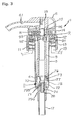
second spring member 74 ofsuction valve 7 may take on various forms and is not limited to the one noted above. Essentially,second spring member 74 must be resilient enough to maintainsuction valve 7 in the closed condition untildischarge valve 9 closes at the end of the back-suction phase. Afterdischarge valve 9 closes at the end of the back-suction phase, the negative pressure existing withinpump chamber 2 overcomes the resilient strength ofsecond spring member 74 to opensuction valve 7, initiating the suction mode. - Figs. 5(a), 5(b), 5(c) and 6 illustrate another embodiment of the present invention. Referring first to Figs. 5(a) and 5(b), a
rachet mechanism 26 has apiston rachet 76b and stopper rachet 76a.Piston rachet 76b is located onpiston 4 and facessuction valve stopper 76. Stopper rachet 76a is located onsuction valve stopper 73 and facespiston 4. Stopper ratchet 76a andpiston ratchet 76b include a plurality of teeth arranged on facing surfaces ofsuction valve stopper 76 andpiston 4, respectively. Stopper ratchet 76a andpiston ratchet 76b engage each other whensuction valve stopper 76 andpiston 4 are brought into contact with each other. As such,suction valve body 73 rotates withnozzle 6 andpiston 4. - Fig. 5(a) illustrates a pump of the present invention during the locked state.
Suction valve body 73 is pressed in contact withsuction valve seal 72. If the locked position exists for a long period of time, or if the fluid is highly viscous, the seal betweensuction valve body 73 andsuction valve seat 72 may adhere to each other such thatsuction valve body 73 cannot reciprocate withinsuction valve 7 as it should during normal operation. Stopper ratchet 76a andpiston ratchet 76b alleviate this problem by preventingsuction valve body 73 from adhering tosuction valve seat 72. -
Suction valve body 73 rotates withnozzle 6 whilemale locking thread 15 is unscrewed fromfemale locking thread 16. The rotation ofsuction valve body 73 thereby breaks the seal betweensuction valve head 75 andsuction valve seat 72 via shearing. This allowssuction valve body 73 to reciprocate withinsuction valve 7 as it should during normal pump operation, as shown by Figs. 5(b) and 6.Suction valve body 73 is reliably released whenmale locking thread 15 andfemale locking thread 16 are disengaged, even if the load from locking causessuction valve body 73 to adhere tosuction valve seat 72. - Referring now to Figs. 5(a) and 5(c), a plurality of
vertical discharge ribs 94 are arranged radially within connectingchamber 8.Discharge ribs 94 preventdischarge valve body 93 from sticking to the wall of connectingpassage 8 during the discharge phase and back-suction phase.Discharge valve body 93 has a tendency to adhere to the inner wall of connectingchamber 8 when pumping highly viscous fluid, which decreases the efficiency ofpump 1.Discharge ribs 94 guidedischarge valve body 93 within connectingchamber 8 so thatdischarge valve body 93 does not contact the inner wall of connectingchamber 8. - The contact area between
discharge valve body 93 anddischarge ribs 94 is less than the contact area betweendischarge valve body 93 and the inner wall of connectingchamber 8. The decrease in contact area reduces the drag exerted ondischarge valve body 93 as it moves within connectingchamber 8. The present invention is thus capable of pumping highly viscous fluids withoutdischarge valve body 93 adhering to connectingchamber 8. This increases the efficiency ofpump 1. -
Pump 1 has a firstspring member guide 21 which guidesfirst spring member 10 through all phases of pump operation so thatfirst spring member 10 does not impede the reciprocating movement ofpiston 4 withinpump chamber 2. Firstspring member guide 21 also prevents wear betweenfirst spring member 10 and the inner perimeter ofpump chamber 2. - First
spring member guide 21 consists of a plurality of vertical ribs extending radially on the inner perimeter ofpump chamber 2. Firstspring member guide 21 starts atfirst spring seat 10a and extends upward along the inner perimeter ofpump chamber 2 to the approximate point wherepiston 4 is positioned during the locked state. Firstspring member guide 21 may also constitute a continuous ridge extending over the entire inner perimeter ofpump chamber 2 in the same vertical location as described above. - Referring now to Figs. 5(a) and 6, the upper end of
first spring member 10 is held and guided in a ring-shaped gap in the lower end ofpiston 4, providing further reliability in preventing interference between the outer perimeter offirst spring member 10 and the inner perimeter ofpump chamber 2. - In the present invention, as described above,
second spring member 74 keepssuction valve 7 in a closed state untildischarge valve 9 is completely closed following the completion of the discharge and back suction phases. Thus, fluid remaining innozzle 6 is returned to pumpchamber 2, which prevents dripping that occurs in prior art pumps. This conserves the amount of fluid dispensed and eliminates unwanted waste and mess. - Additionally, if the internal pressure of fluid container 19 (not shown) increases due to an increase in temperature,
second spring member 74 maintainssuction valve 7 in a closed state, thereby preventing fluid from flowing from main fluid container 19 (not shown) intopump chamber 2. This eliminates undesirable dripping and unwanted mess. - Furthermore, if
suction valve body 73 ofsuction valve 7 is made out of a hollow resin member,suction valve body 73 can respond sensitively to changes in pressure to operate accurately and reliably. The resiliency ofsuction valve body 73 is also increased due to the resin composition, thereby improving the seal betweensuction valve head 75 andsuction valve seat 72. - Through the use of
piston rachet 76b and stopper rachet 76a ofrachet mechanism 26 it is possible to break the seal betweensuction valve seat 72 andsuction valve head 75 when the pump is unlocked by rotatingsuction valve body 73. This action releasessuction valve body 73 and provides smooth and unencumbered operation ofsuction valve 7. - Adding
discharge ribs 94 on the inner wall of connectingchamber 8 maintains a gap betweendischarge valve body 93 and the inner wall of connectingchamber 8, preventingdischarge valve body 93 from sticking, lodging, or in any way adhering to the inner wall of connectingchamber 8 when a high viscosity fluid is used. This provides smooth and uninhibited operation ofdischarge valve 9. - When
first spring member 10 comprises a coil spring, first spring guides 21 can be arranged on the inner perimeter surface ofpump chamber 2 to prevent interference between the outer perimeter offirst spring member 10 and the inner perimeter ofpump chamber 2. This provides smooth operation offirst spring member 10 withinpump chamber 2 with minimal interference. - Having described the preferred embodiments of the invention with reference to the accompanying drawings, it is to be understood that the invention is not limited to those precise embodiments, and that various changes and modifications may be effected therein by one skilled in the art without departing from the scope or spirit of the invention as defined in the appended claims.
Claims (26)
- A pump, comprising:
a pump chamber having an upper end and a lower end;
means for altering the pressure in said pump chamber;
a first check valve having means for permitting a return flow of fluid before closing fully;
a second check valve having means for remaining closed until a specified threshold negative pressure exists in said pump chamber; and
said first check valve being connected to said second check valve by said pump chamber. - A pump as claimed in Claim 1, wherein:
said means for altering the pressure in said pump chamber includes a piston and a spring member;
said piston is slidably disposed in said pump chamber having an upper end and a lower end; and
said spring member is compressibly interposed between said lower end of said piston and said lower end of said pump chamber biasing said piston toward a ready position where the volume in said pump chamber is at a maximum. - A pump as claimed in Claim 1, wherein:
said means for permitting a return flow of fluid includes a valve body, a valve seat, and a means for stopping said valve body;
said valve seat is disposed within a connecting chamber; and
said connecting chamber connects said pump chamber to an exit passage of a nozzle. - A pump as claimed in Claim 3 and further, wherein:
said valve seat cooperates with said valve body for providing a means for regulating a flow of fluid from said pump chamber to said exit passage, and from said exit passage to said pump chamber;
said valve body traveling away from said valve seat during a period of positive pressure in said pump chamber, coming to rest against said means for stopping at a predetermined distance from said valve seat in said connecting chamber; and
said valve body traveling away from said means for stopping toward said valve seat during a period of negative pressure in said pump chamber, coming to rest against said valve seat to stop a return flow of fluid from said exit passage to said pump chamber. - A pump as claimed in Claim 4 and further, wherein:
said valve body has a contact surface of sufficient size to provide a seal between said valve body and said valve seat; and
said valve body has a specific weight less than the specific weight of the fluid so as to lengthen the time of said return flow of fluid from said exit passage to said pump chamber. - A pump as claimed in Claim 4 and further, wherein:
said means for stopping consists of a stopper; and
said stopper being attached to said nozzle so as to prohibit said valve body from blocking fluid flow through said exit passage. - A pump as claimed in Claim 6 and further, wherein:
said stopper extends from said nozzle toward said valve seat; and
said stopper is concentrically disposed in said connecting chamber. - A pump as claimed in Claim 4 and further, wherein:
said means for stopping consists of a stopper ring;
said stopper ring located between said valve seat and said exit passage; and
said stopper ring having a plurality of projections extending radially inward from said connecting chamber toward a center thereof, allowing fluid to flow past said valve body after said valve body comes in contact with said stopper ring. - A pump as claimed in Claim 1 and further, wherein:
said means for remaining closed of said second check valve includes a valve body, a valve seat, and a means for biasing said valve body against said valve seat. - A pump as claimed in Claim 9 and further, wherein:
said valve body includes a valve head, a valve stopper, means for guiding said valve body in a valve opening, and means for strengthening a seal between said valve head and said valve seat in a locked position; and
said valve head cooperates with said valve seat to regulate the flow of fluid from said main fluid container to said pump chamber. - A pump as claimed in Claim 10 and further, wherein:
said valve body is made out of a resin material;
said means for strengthening includes a plurality of stopper notches extending from said valve head toward said valve stopper;
said valve stopper having a larger diameter than said valve head; and
wherein said lower end of said piston is forced into contact with said valve stopper during said locked position, thereby compressing said stopper notches between said valve stopper and said valve head to strengthen said seal between said valve head and said valve seat. - A pump as claimed in Claim 10 and further, wherein:
said means for biasing is compressibly interposed between an inner lip of said valve opening and said means for guiding said valve body in said valve opening; and
said means for biasing forces said means for guiding away from said valve seat toward said main fluid container, thereby pulling said valve head into contact with said valve seat. - A pump as claimed in Claim 10 and further, wherein:
said means for biasing is compressibly interposed between an inner lip of an extension chamber and a surface of said valve head facing said pump chamber;
said extension chamber extending from said valve seat into said pump chamber; and
said means for biasing forces said valve head toward said valve seat, thereby pushing said valve head into contact with said valve seat. - A pump as claimed in Claim 2 and further, wherein:
said pump chamber has a guide member for guiding said spring member within said pump chamber during the compression and expansion of said spring member;
said guide member being located on an inner perimeter of said lower end of said pump chamber; and
said guide member extending from said lower end of said pump chamber to a point approximately equal an upper end of said second check valve. - A pump as claimed in Claim 2 and further, wherein:
said piston and said upper end of said second check valve have a means for disengaging said second check valve from a locked position. - A pump as claimed in Claim 15 and further, wherein:
said means for disengaging includes a piston rachet located on said lower end of said piston, and a valve rachet located on said upper end of said second check valve;
said piston rachet including a plurality of projections extending from said lower end of said piston toward said lower end of said pump chamber;
said valve rachet including a plurality of projections extending from said upper end of said second check valve toward said upper end of said pump chamber; and
said piston rachet and said valve rachet engaging so that said second check valve rotates corresponding to the rotation of said piston to break a seal between said second check valve and said pump chamber to allow said second check valve to reciprocate freely within said pump chamber. - A pump as claimed in Claim 3 and further, wherein:
said connecting chamber has ribs disposed radially therein to prevent said valve body from adhering to said connecting chamber during said travel of said valve body within said connecting chamber; and
said ribs being interspersed within said connecting chamber to maintain said valve body at a specified distance from said connecting chamber. - A pump comprising:
a pump chamber having a lower end and an upper end;
a nozzle having an exit passage;
a connecting chamber connecting said pump chamber to said exit passage of said nozzle;
a piston slidably disposed within said pump chamber having a lower end facing said pump chamber and an upper end fixedly attached to said nozzle;
a first spring member compressibly interposed between said lower end of said piston and said lower end of said pump chamber biasing said piston so as to cause the volume within said pump chamber to be at a maximum;
said piston reducing the volume of said pump chamber in response to an external pressure applied to said nozzle, creating a positive pressure within said pump chamber;
said piston expanding the volume within said pump chamber in response to removal of said external pressure applied to said nozzle, creating a negative pressure within said pump chamber; and
said negative pressure having a suction portion and a back-suction portion. - A pump as claimed in Claim 18 and further, including:
a suction valve disposed within said lower end of said pump chamber controlling fluid ingress from said main fluid container to said pump chamber;
said suction valve having a valve body, a valve opening, and a valve seat;
a suction spring member;
said suction spring member biasing said valve body of said suction valve against said valve seat of said suction valve such that fluid ingress from a main fluid container to said pump chamber occurs during said suction portion of said negative pressure; and
said suction spring member biasing said valve body of said suction valve against said valve seat of said suction valve such that said suction valve remains closed during said back suction portion of said negative pressure. - A pump as claimed in Claim 18 and further, including:
a discharge valve disposed within said connecting chamber having a discharge valve body, a discharge valve opening, a discharge valve seat, and a discharge valve stopper;
said discharge valve permitting fluid egress from said pump chamber to said exit passage of said nozzle during said positive pressure;
said discharge valve permitting an ingress of fluid remaining within said exit passage of said nozzle after said positive pressure to said pump chamber;
said discharge valve stopper having a single element disposed in said connecting chamber preventing said discharge valve body from traveling into said exit passage of said nozzle during said positive pressure; and
said valve body of said discharge valve returning to said valve seat of said discharge valve during said back suction portion of said negative pressure, closing said discharge valve. - A pump as described in Claim 18 and further, including:
a discharge valve disposed within said connecting chamber having a discharge valve body, a discharge valve opening, a discharge valve seat, and a discharge valve stopper;
said discharge valve permitting fluid egress from said pump chamber to said exit passage of said nozzle during said positive pressure;
said discharge valve permitting an ingress of fluid remaining within said exit passage of said nozzle after said positive pressure to said pump chamber;
said discharge valve stopper having a ring element disposed in said connecting chamber preventing said discharge valve body from traveling into said exit passage of said nozzle during said positive pressure;
said ring element having a plurality of projections extending radially in said connecting chamber from said connecting chamber toward a center thereof; and
said valve body of said discharge valve returning to said valve seat of said discharge valve during said back suction portion of said negative pressure, closing said discharge valve. - A pump as described in Claim 18 and further, including:
locking means for selectively locking said piston in contact with said valve body of said suction valve;
said valve body of said suction valve having a stopper, a valve head, and a guide piece;
said valve head of said valve body contacting said valve seat of said suction valve during said positive pressure and during said back suction portion of said negative pressure;
said stopper of said valve body of said suction valve having stopper notches serving to increase the resiliency of said stopper of said valve body of said suction valve;
said guide piece having a first end integrally attached to said suction valve head and a second end extending through said suction valve opening toward said main fluid container; and
said second spring member compressibly interposed between said suction valve seat and said second end of said guide piece. - A pump as described in Claim 18 and further, comprising:
locking means for selectively locking said piston in contact with said valve body of said suction valve;
said valve body of said suction valve having a stopper, a valve head, and a plurality of guide pieces;
said valve head of said valve body contacting said valve seat of said suction valve during said positive pressure and during said back suction portion of said negative pressure;
said stopper of said valve body of said suction valve having stopper notches serving to increase the resiliency of said stopper of said valve body of said suction valve;
said guide pieces having first ends integrally attached to said suction valve head and second ends extending through said suction valve opening toward said main fluid container; and
said second spring member compressibly interposed between said suction valve seat and said second ends of said guide pieces. - A pump as described in Claim 21 and further, wherein:
said stopper of said valve body of said suction valve is integrally attached to said valve head of said valve body of said suction valve and extends away from said valve seat of said valve body of said suction valve in a reverse conical fashion. - A pump as claimed in Claim 20 and further, wherein:
said discharge valve body is made of a resilient resin material with a specific gravity less than said fluid. - A pump comprising:
a pump chamber;
means for selectively creating a negative pressure and a positive pressure in said pump chamber;
a suction valve for admitting a fluid to said pump chamber in a presence of said negative pressure;
a discharge valve for releasing said fluid from said pump chamber in a presence of said positive pressure; and
means for maintaining said suction valve in a closed condition until a predetermined value of said negative pressure exists in said pump chamber.
Priority Applications (2)
| Application Number | Priority Date | Filing Date | Title |
|---|---|---|---|
| US08/285,386 US5549223A (en) | 1994-08-03 | 1994-08-03 | Pump with back suction phase |
| EP94112408A EP0696478A1 (en) | 1994-08-03 | 1994-08-09 | Pump |
Applications Claiming Priority (2)
| Application Number | Priority Date | Filing Date | Title |
|---|---|---|---|
| US08/285,386 US5549223A (en) | 1994-08-03 | 1994-08-03 | Pump with back suction phase |
| EP94112408A EP0696478A1 (en) | 1994-08-03 | 1994-08-09 | Pump |
Publications (1)
| Publication Number | Publication Date |
|---|---|
| EP0696478A1 true EP0696478A1 (en) | 1996-02-14 |
Family
ID=26135770
Family Applications (1)
| Application Number | Title | Priority Date | Filing Date |
|---|---|---|---|
| EP94112408A Withdrawn EP0696478A1 (en) | 1994-08-03 | 1994-08-09 | Pump |
Country Status (2)
| Country | Link |
|---|---|
| US (1) | US5549223A (en) |
| EP (1) | EP0696478A1 (en) |
Cited By (6)
| Publication number | Priority date | Publication date | Assignee | Title |
|---|---|---|---|---|
| WO1999033575A1 (en) * | 1997-12-25 | 1999-07-08 | Yaowu Ding | Waterproof mechanism for emulsion dispensing pump |
| WO1999048766A1 (en) * | 1998-03-26 | 1999-09-30 | Valois S.A. | Airless dispensing device |
| WO2000018513A1 (en) * | 1998-09-25 | 2000-04-06 | Rieke Packaging Systems Limited | Dispenser pumps |
| EP1388500A3 (en) * | 2002-08-08 | 2006-05-03 | Saint-Gobain Calmar Inc. | Pump dispenser having an improved discharge valve |
| CN111920324A (en) * | 2020-08-27 | 2020-11-13 | 浙江英特汉莎智能科技有限公司 | Soap dispenser |
| CN113474087A (en) * | 2019-01-08 | 2021-10-01 | 泰普勒斯特有限责任公司 | Device for dispensing a fluid or a mixture |
Families Citing this family (28)
| Publication number | Priority date | Publication date | Assignee | Title |
|---|---|---|---|---|
| GB9405891D0 (en) * | 1994-03-24 | 1994-05-11 | English Glass Company The Limi | Dispenser pumps |
| CN1098200C (en) * | 1995-01-27 | 2003-01-08 | 株式会社吉野工业所 | liquid ejection pump |
| US5687877A (en) * | 1995-11-03 | 1997-11-18 | Owens-Illinois Closure Inc. | Pump dispenser having moveable outlet check valve element |
| US5715973A (en) * | 1996-02-01 | 1998-02-10 | Contico International, Inc. | Manually operated fluid pump for dispensing lotion and the like |
| US6173863B1 (en) * | 1999-08-09 | 2001-01-16 | Owens-Illinois Closure Inc. | Pump dispenser having a plunger seal |
| US6230942B1 (en) * | 1999-10-21 | 2001-05-15 | Roy Kuo | Metered dispensing pump device preventable of water permeation |
| US6708852B2 (en) * | 2001-08-20 | 2004-03-23 | Alternative Packaging Solutions, L.P. | Non-chemical aerosol dispenser |
| USD459654S1 (en) | 2001-09-01 | 2002-07-02 | Roy Kuo | Dispenser head |
| US6604656B1 (en) * | 2002-02-11 | 2003-08-12 | Living Fountain Plastic Industrial Co., Ltd. | Safety lock ring structure of a dispenser pump |
| US6966459B1 (en) * | 2003-04-07 | 2005-11-22 | Living Fountain Plastic Industrial Co., Ltd. | Water infiltration-proof structure |
| DE102005009295A1 (en) * | 2004-07-13 | 2006-02-16 | Ing. Erich Pfeiffer Gmbh | Dosing device for media |
| US20070080174A1 (en) * | 2005-10-06 | 2007-04-12 | Coe Matthew T | Fluid dispenser with a safety dispensing actuator and fluid dispensing product containing the same |
| US20080006656A1 (en) * | 2006-07-10 | 2008-01-10 | Living Fountain Plastic Industrial Co., Ltd. | Lotion pump structure |
| US7726517B2 (en) * | 2007-06-27 | 2010-06-01 | The Clorox Company | Liquid draw-back system for a dispensing package |
| EP2330049B1 (en) * | 2008-09-30 | 2017-11-15 | Yoshino Kogyosho Co., Ltd. | Head-side module of discharge pump for discharge container, and discharge pump comprising head-side module and pump-side module |
| US8113389B2 (en) * | 2008-12-08 | 2012-02-14 | Kimberly-Clark Worldwide, Inc. | Anti drip fluid dispenser |
| WO2010083419A1 (en) * | 2009-01-16 | 2010-07-22 | Colgate-Palmolive Company | Dispensing container comprising a pump receiving fitment |
| KR101614165B1 (en) * | 2010-01-12 | 2016-04-20 | 동부대우전자 주식회사 | Apparatus for supplying liquid detergent |
| CN102770666B (en) * | 2010-01-28 | 2015-11-25 | 株式会社吉野工业所 | Pump |
| DE102010045059A1 (en) * | 2010-09-10 | 2012-03-15 | F. Holzer Gmbh | metering |
| US9415401B2 (en) | 2012-04-04 | 2016-08-16 | Alternative Packaging Solutions Llc | One turn actuated duration spray pump mechanism |
| USD717666S1 (en) | 2014-03-14 | 2014-11-18 | The Clorox Company | Fluid dispenser |
| US10010897B2 (en) * | 2015-07-20 | 2018-07-03 | Silgan Dispensing Systems Corporation | Pump dispenser with locking feature |
| EP3630371B1 (en) * | 2017-05-25 | 2023-07-05 | Rieke Packaging Systems Limited | Dispenser pumps and dispensers |
| KR102171859B1 (en) * | 2019-01-07 | 2020-10-29 | (주)연우 | A button retractable type container for cometics |
| JP7365210B2 (en) * | 2019-11-29 | 2023-10-19 | 株式会社吉野工業所 | discharge pump |
| IT202100025532A1 (en) * | 2021-10-07 | 2023-04-07 | Silgan Dispensing Systems Milano S R L | MANUALLY OPERATED PUMP |
| CN117465829A (en) * | 2023-10-30 | 2024-01-30 | 天舟医疗(苏州)有限公司 | a product dispenser |
Citations (10)
| Publication number | Priority date | Publication date | Assignee | Title |
|---|---|---|---|---|
| CH415486A (en) * | 1963-06-21 | 1966-06-15 | Lanvin Parfums Inc | Sprayer |
| US3361078A (en) * | 1965-12-15 | 1968-01-02 | Diamond Int Corp | Liquid dispenser |
| US4154374A (en) * | 1977-10-03 | 1979-05-15 | Ethyl Products Company | Finger operated spray pump |
| FR2532010A1 (en) * | 1982-08-23 | 1984-02-24 | Realex Corp | MANUAL DISPENSING PUMP FOR FLUID PRODUCT CONTAINER |
| US4524888A (en) * | 1981-07-30 | 1985-06-25 | Canyon Corporation | Dispenser |
| EP0378286A2 (en) * | 1989-01-07 | 1990-07-18 | Colgate-Palmolive Company | Dispenser |
| EP0487412A1 (en) * | 1990-11-21 | 1992-05-27 | Societe De Promotion, Recherche Et Innovation Technologique | Metering valve for liquids contained in a pressureless container |
| EP0498275A1 (en) * | 1991-02-07 | 1992-08-12 | Tetsuya Tada | A pump dispenser and a primary valve thereof |
| JPH0674147A (en) * | 1992-08-25 | 1994-03-15 | Toyo Seikan Kaisha Ltd | Pump |
| FR2699390A1 (en) * | 1992-12-23 | 1994-06-24 | Sodex Hexotol Sa | Distributor for gels or low viscosity products |
Family Cites Families (4)
| Publication number | Priority date | Publication date | Assignee | Title |
|---|---|---|---|---|
| US3128018A (en) * | 1961-07-07 | 1964-04-07 | Drackett Co | Fluid dispensing pump with sealing means |
| US4286736A (en) * | 1980-02-20 | 1981-09-01 | Diamond International Corporation | Liquid Dispenser |
| FR2526403A1 (en) * | 1982-05-10 | 1983-11-10 | Ethyl Prod | HAND-OPERATED PUMP ASSEMBLY |
| US4538748A (en) * | 1983-02-16 | 1985-09-03 | Realex Corporation | Tamper deterring unlocking restricter for down locking pump dispensers |
-
1994
- 1994-08-03 US US08/285,386 patent/US5549223A/en not_active Expired - Lifetime
- 1994-08-09 EP EP94112408A patent/EP0696478A1/en not_active Withdrawn
Patent Citations (10)
| Publication number | Priority date | Publication date | Assignee | Title |
|---|---|---|---|---|
| CH415486A (en) * | 1963-06-21 | 1966-06-15 | Lanvin Parfums Inc | Sprayer |
| US3361078A (en) * | 1965-12-15 | 1968-01-02 | Diamond Int Corp | Liquid dispenser |
| US4154374A (en) * | 1977-10-03 | 1979-05-15 | Ethyl Products Company | Finger operated spray pump |
| US4524888A (en) * | 1981-07-30 | 1985-06-25 | Canyon Corporation | Dispenser |
| FR2532010A1 (en) * | 1982-08-23 | 1984-02-24 | Realex Corp | MANUAL DISPENSING PUMP FOR FLUID PRODUCT CONTAINER |
| EP0378286A2 (en) * | 1989-01-07 | 1990-07-18 | Colgate-Palmolive Company | Dispenser |
| EP0487412A1 (en) * | 1990-11-21 | 1992-05-27 | Societe De Promotion, Recherche Et Innovation Technologique | Metering valve for liquids contained in a pressureless container |
| EP0498275A1 (en) * | 1991-02-07 | 1992-08-12 | Tetsuya Tada | A pump dispenser and a primary valve thereof |
| JPH0674147A (en) * | 1992-08-25 | 1994-03-15 | Toyo Seikan Kaisha Ltd | Pump |
| FR2699390A1 (en) * | 1992-12-23 | 1994-06-24 | Sodex Hexotol Sa | Distributor for gels or low viscosity products |
Non-Patent Citations (1)
| Title |
|---|
| PATENT ABSTRACTS OF JAPAN vol. 18, no. 325 (M - 1625) 21 June 1994 (1994-06-21) * |
Cited By (11)
| Publication number | Priority date | Publication date | Assignee | Title |
|---|---|---|---|---|
| WO1999033575A1 (en) * | 1997-12-25 | 1999-07-08 | Yaowu Ding | Waterproof mechanism for emulsion dispensing pump |
| US6357629B1 (en) | 1997-12-25 | 2002-03-19 | Yaowu Ding | Waterproof mechanism for emulsion dispensing pump |
| EP1043076A4 (en) * | 1997-12-25 | 2006-05-24 | Yaowu Ding | Waterproof mechanism for emulsion dispensing pump |
| WO1999048766A1 (en) * | 1998-03-26 | 1999-09-30 | Valois S.A. | Airless dispensing device |
| FR2776633A1 (en) * | 1998-03-26 | 1999-10-01 | Valois Sa | AIRLESS DISTRIBUTION DEVICE |
| US6332561B1 (en) | 1998-03-26 | 2001-12-25 | Valois S.A. | Airless dispensing device |
| WO2000018513A1 (en) * | 1998-09-25 | 2000-04-06 | Rieke Packaging Systems Limited | Dispenser pumps |
| EP1388500A3 (en) * | 2002-08-08 | 2006-05-03 | Saint-Gobain Calmar Inc. | Pump dispenser having an improved discharge valve |
| CN113474087A (en) * | 2019-01-08 | 2021-10-01 | 泰普勒斯特有限责任公司 | Device for dispensing a fluid or a mixture |
| CN113474087B (en) * | 2019-01-08 | 2023-07-14 | 泰普勒斯特有限责任公司 | Devices for dispensing fluids or mixtures |
| CN111920324A (en) * | 2020-08-27 | 2020-11-13 | 浙江英特汉莎智能科技有限公司 | Soap dispenser |
Also Published As
| Publication number | Publication date |
|---|---|
| US5549223A (en) | 1996-08-27 |
Similar Documents
| Publication | Publication Date | Title |
|---|---|---|
| US5549223A (en) | Pump with back suction phase | |
| US5806721A (en) | Container mounted pump dispenser with back suction | |
| EP1543886B1 (en) | Liquid jet pump comprising a discharge valve opening bar | |
| US4957218A (en) | Foamer and method | |
| US5803318A (en) | Precompression pump | |
| US4079865A (en) | Non-pulsating, non-throttling, vented pumping system for continuously dispensing product | |
| EP0755305B1 (en) | Manually operated reciprocating liquid pump | |
| US5038965A (en) | Pump dispenser for delivering a predetermined dosage regardless of method of actuation | |
| EP0297751B1 (en) | Viscous product dispenser | |
| US7815076B2 (en) | Vacuum released valve | |
| US4109832A (en) | Pumping system having a pressure release | |
| US3228347A (en) | Pump | |
| US4692103A (en) | Precise output pump sprayer | |
| JPS6362263B2 (en) | ||
| US5816453A (en) | Dispenser pump | |
| US4231493A (en) | Lever pump with button actuator | |
| JPS61174959A (en) | Weighing distribution pump | |
| KR880001134B1 (en) | Manually operated dispensing pump | |
| WO1985004852A1 (en) | Pump for dispensing liquid from a container | |
| EP1115500B1 (en) | Dispenser pumps | |
| US5307962A (en) | Container mounted pump with improved check valve structure | |
| US4993600A (en) | Liquid dispenser pump | |
| US7556178B2 (en) | One-way valve and vacuum relief device | |
| US3500760A (en) | Pump for an atomizer or the like | |
| JP3163776B2 (en) | pump |
Legal Events
| Date | Code | Title | Description |
|---|---|---|---|
| PUAI | Public reference made under article 153(3) epc to a published international application that has entered the european phase |
Free format text: ORIGINAL CODE: 0009012 |
|
| AK | Designated contracting states |
Kind code of ref document: A1 Designated state(s): DE FR GB |
|
| 17P | Request for examination filed |
Effective date: 19960301 |
|
| 17Q | First examination report despatched |
Effective date: 19970612 |
|
| STAA | Information on the status of an ep patent application or granted ep patent |
Free format text: STATUS: THE APPLICATION HAS BEEN WITHDRAWN |
|
| 18W | Application withdrawn |
Withdrawal date: 19971212 |