EP0696356B1 - Device for measuring magnetic fields - Google Patents
Device for measuring magnetic fields Download PDFInfo
- Publication number
- EP0696356B1 EP0696356B1 EP95907117A EP95907117A EP0696356B1 EP 0696356 B1 EP0696356 B1 EP 0696356B1 EP 95907117 A EP95907117 A EP 95907117A EP 95907117 A EP95907117 A EP 95907117A EP 0696356 B1 EP0696356 B1 EP 0696356B1
- Authority
- EP
- European Patent Office
- Prior art keywords
- magnetic field
- magnetization
- field sensors
- sensor elements
- coil
- Prior art date
- Legal status (The legal status is an assumption and is not a legal conclusion. Google has not performed a legal analysis and makes no representation as to the accuracy of the status listed.)
- Expired - Lifetime
Links
- 230000005291 magnetic effect Effects 0.000 title claims description 116
- 230000005415 magnetization Effects 0.000 claims description 77
- 239000011888 foil Substances 0.000 claims description 27
- 239000004020 conductor Substances 0.000 claims description 18
- 239000012777 electrically insulating material Substances 0.000 claims description 3
- 239000011265 semifinished product Substances 0.000 description 7
- 230000000694 effects Effects 0.000 description 6
- 238000005259 measurement Methods 0.000 description 5
- XEEYBQQBJWHFJM-UHFFFAOYSA-N Iron Chemical compound [Fe] XEEYBQQBJWHFJM-UHFFFAOYSA-N 0.000 description 4
- 238000004519 manufacturing process Methods 0.000 description 4
- 229920002994 synthetic fiber Polymers 0.000 description 3
- PXHVJJICTQNCMI-UHFFFAOYSA-N Nickel Chemical compound [Ni] PXHVJJICTQNCMI-UHFFFAOYSA-N 0.000 description 2
- 238000010586 diagram Methods 0.000 description 2
- 229910052742 iron Inorganic materials 0.000 description 2
- 239000000696 magnetic material Substances 0.000 description 2
- 229910000889 permalloy Inorganic materials 0.000 description 2
- RYGMFSIKBFXOCR-UHFFFAOYSA-N Copper Chemical compound [Cu] RYGMFSIKBFXOCR-UHFFFAOYSA-N 0.000 description 1
- XUIMIQQOPSSXEZ-UHFFFAOYSA-N Silicon Chemical compound [Si] XUIMIQQOPSSXEZ-UHFFFAOYSA-N 0.000 description 1
- 230000006978 adaptation Effects 0.000 description 1
- 229910045601 alloy Inorganic materials 0.000 description 1
- 239000000956 alloy Substances 0.000 description 1
- 229910052802 copper Inorganic materials 0.000 description 1
- 239000010949 copper Substances 0.000 description 1
- 238000001514 detection method Methods 0.000 description 1
- 230000008030 elimination Effects 0.000 description 1
- 238000003379 elimination reaction Methods 0.000 description 1
- 230000005294 ferromagnetic effect Effects 0.000 description 1
- 229910052759 nickel Inorganic materials 0.000 description 1
- 229920003223 poly(pyromellitimide-1,4-diphenyl ether) Polymers 0.000 description 1
- 229910052710 silicon Inorganic materials 0.000 description 1
- 239000010703 silicon Substances 0.000 description 1
- 239000007787 solid Substances 0.000 description 1
- 239000000758 substrate Substances 0.000 description 1
Images

Classifications
-
- G—PHYSICS
- G01—MEASURING; TESTING
- G01R—MEASURING ELECTRIC VARIABLES; MEASURING MAGNETIC VARIABLES
- G01R33/00—Arrangements or instruments for measuring magnetic variables
- G01R33/02—Measuring direction or magnitude of magnetic fields or magnetic flux
- G01R33/06—Measuring direction or magnitude of magnetic fields or magnetic flux using galvano-magnetic devices
- G01R33/09—Magnetoresistive devices
-
- G—PHYSICS
- G01—MEASURING; TESTING
- G01R—MEASURING ELECTRIC VARIABLES; MEASURING MAGNETIC VARIABLES
- G01R33/00—Arrangements or instruments for measuring magnetic variables
- G01R33/02—Measuring direction or magnitude of magnetic fields or magnetic flux
- G01R33/0206—Three-component magnetometers
Definitions
- the invention relates to a device for measuring magnetic fields, comprising an assembly consisting of at least three magnetic field sensors, each of which comprises a number of magnetoresistive sensor elements which are situated in one plane and which have the same privileged directions of magnetization, said sensor elements being connected on the one side to a power supply circuit and on the other side to a signal processing circuit, the privileged directions of magnetization of the sensor elements of different magnetic field sensors being different, said assembly of magnetic field sensors being arranged within a magnetization coil which is formed as an electric conductor which extends around a central axis in a number of turns and which is arranged to generate an auxiliary magnetic field extending parallel to the central axis, the magnetic field sensors being arranged within the magnetization coil in such a manner that the angle enclosed by the central axis relative to the normal to the plane of the sensor elements is the same for each of the magnetic field sensors and that the auxiliary magnetic field at the area of each of the magnetic field sensors contains a component which extends parallel to the privileged direction of magnetization of the sensor elements of the relevant
- a similar device comprising two magetic sensors is known from Philips Technical Publication 268.
- the magnetization coil is connected to a current pulse generator which is arranged to supply the magnetization coil with current pulses of opposite current direction in an alternating fashion, the arrangement being such that each current pulse generates a magnetic field in the magnetization coil which extends parallel to the privileged directions of magnetization of the sensor elements and which is strong enough to reverse the direction of the internal magnetization of the sensor elements.
- the reversal of the internal magnetization of the sensor elements serves to eliminate effects disturbing the measurement, for example as caused by manufacturing tolerances and by drift due to temperature variations.
- the assembly of the known device may comprise two magnetic field sensors which are mounted perpendicularly to one another, as shown in Fig.
- a first drawback of the known device consists in that it is not readily possible to mount a third magnetic field sensor so that the privileged direction of magnetization of the sensor elements of the third magnetic field sensor extends perpendicularly to that of the sensor elements of the first two magnetic field sensors.
- the auxiliary magnetic field would then extend perpendicularly to the plane of the sensor elements of the third magnetic field sensor, so that it would not have the desired effect. Therefore, a separate magnetization coil would be required for the third magnetic field sensor, which would make the device particularly voluminous and heavy. Nevertheless, it is often desirable to detect three mutually perpendicular components of a magnetic field.
- the known device is suitable. However, it may then be objectionable that the magnetization coil is comparatively voluminous and heavy because it must enclose the entire volume defined by the mutually perpendicular magnetic field sensors. Consequently, the known device is not very well suitable for applications where at least the part containing the magnetic field sensor must be very small and light.
- An example of such an application is a compass in a vehicle, for example a car.
- the device then serves to detect the direction of the horizontal components of the terrestrial magnetic field and it would be desirable to mount the magnetic field sensor outside the car body, because the car body generally comprises a large amount of iron and thus has a disturbing effect on the local terrestrial field.
- a suitable location for the sensor is, for example the tip of an aerial mounted on the vehicle.
- the sensor and the magnetization coil connected thereto should then be extremely small and light.
- the associated circuits can then be accommodated within the vehicle, so that they may be more voluminous and heavier.
- the device in accordance with the invention comprises an assembly of at least three magnetic field sensors, and a coil which is formed as an electrical conductor which extends around a central axis in a number of turns and which is arranged to generate an auxiliary magnetic field extending parallel to the central axis, characterized in that each of the magnetic field sensors comprises several magnetoresistive sensor elements which are situated in one plane and which have the same privileged directions of magnetization, said sensor elements being connected on the one side to a power circuit and on the other side to a signal processing circuit, the privileged directions of magnetization of the sensor elements of different magnetic field sensors being different, the magnetic field sensors being arranged within the magnetization coil in such a manner that the angle enclosed by the central axis relative to the normal to the plane in which the sensor elements are situated is the same for each of the magnetic field sensors and that the auxiliary magnetic field at the area of the magnetic field sensors contains a component which extends parallel to the privileged directions of magnetization of the sensor elements of the relevant magnetic field sensor, and the direction of the auxiliary magnetic
- the auxiliary magnetic field has a component parallel to the privileged direction of magnetization of each of the sensor elements, these components being equally large for all sensor elements.
- a device for measuring magnetic fields by means of three magnetic field sensors in an auxiliary magnetic field generated by a single magnetization coil is known per se from EP-A-0 290 811.
- the magnetization coil is wound on a toroidal support provided with recesses for accommodating the magnetic field sensors, so that the auxiliary magnetic field extends parallel to the privileged direction of magnetization for each magnetic field sensor.
- the sensor part thus formed is comparatively voluminous and heavy.
- EP-A-0 411 971 discloses a device for measuring magnetic fields, which comprises three magnetoresistive sensors located on the three faces of a pyramid.
- a magnetisation coil located in a plane perpendicular to the height of the pyramid, is surrounded by the three sensors.
- An embodiment of the device is characterized in that the assembly comprises two magnetic field sensors which are arranged in such a manner that their sensor elements are situated in the same plane or in mutually parallel planes and the privileged directions of magnetization of the sensor elements extend mutually perpendicularly and enclose an angle of 45° relative to the central axis.
- This embodiment is suitable for the measurement of two mutually perpendicular components of a magnetic field. Because the sensor elements of the two magnetic field sensors are situated in one plane or in mutually parallel planes, the assembly consisting of the two magnetic field sensors almost completely fills a very small, block-shaped volume.
- the magnetization coil may have a shape adapted to the shape of this volume, so that it can be substantially smaller than the magnetization coil of the known device.
- a first embodiment of the device in accordance with the invention is characterized in that the assembly comprises three magnetic field sensors which are mounted on three mutually perpendicular surfaces of a support, the plane of the sensor elements of each of the magnetic field sensors extending parallel to one of the three surfaces, said support being arranged within the magnetization coil in such a manner that the normals to the three said surfaces enclose equal angles relative to the central axis.
- This embodiment enables measurement of three mutually perpendicular components of a magnetic field.
- Particularly simple mounting of the magnetic field sensors can be achieved in this embodiment by mounting the magnetic field sensors on first parts of a flexible foil of an electrically insulating material provided with electric conductor tracks which constitute connection conductors for connecting the sensor elements to the power supply circuit and the signal processing circuit, the foil being folded about the support in such a manner that the first parts of the foil are arranged against said surfaces.
- the power supply and signal processing circuits can be provided on the foil itself, if desired. In many cases, however, it will be desirable to avoid increased weight and volume of the combination of magnetic field sensors and magnetization coil due to addition of further components.
- said circuits can be readily mounted at some distance from the magnetic field sensors, which embodiment is characterized in that the foil also comprises a strip-shaped second part on which the conductor tracks continue and which projects from the magnetization coil.
- the assembly formed by the three said magnetic field sensors can be very compact in an embodiment which is characterized in that the support is shaped as at least a part of a cube, so that the three said surfaces adjoin the same comer point of the cube, the axis of the magnetization coil being coincident with a body diagonal of the cube which extends through said comer point.
- the weight can be further reduced when the support is bounded, at the side situated opposite said comer point, by a boundary surface which extends perpendicularly to said body diagonal.
- the assembly of magnetic field sensors can almost completely fill the interior of the magnetization coil if the magnetization coil is shaped as a right-angled prism having a cross-section in the form of an equilateral hexagon.
Landscapes
- Physics & Mathematics (AREA)
- Condensed Matter Physics & Semiconductors (AREA)
- General Physics & Mathematics (AREA)
- Measuring Magnetic Variables (AREA)
Abstract
Description
- Fig. 1 shows a
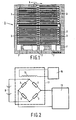
magnetic field sensor 1 which is known per se and which is based on the magnetoresistive effect. This is the phenomenon that the electric resistance of a current-carrying magnetic material changes in the presence of an external magnetic field. This change is caused by a rotation of the magnetization relative to the current direction. For example, in the case of permalloy (a ferromagnetic alloy containing 20% iron and 80% nickel), a rotation of the magnetization through 90° (caused by an external magnetic field extending perpendicularly to the current direction) will cause a change in resistance of from 2 to 3%. In the magnetic field sensor shown (Philips type KMZ 10) fourmagnetoresistive sensor elements 3 are provided on asilicon substrate 2. Each of thesensor elements 3 is formed by a meander-like strip of permalloy having a privileged direction of magnetization parallel to the longitudinal direction of the strip, i.e. in the direction of thearrow 5. The ends of thesensor elements 3 are interconnected so that they form the four branches of a Wheatstone bridge. The degree of unbalance of the bridge can be used as a measure of the variation of the magnetic field strength in the plane of thesensor elements 3 and perpendicular to the direction of an electric current flowing through the sensor elements. The bridge circuit formed by thesensor elements 3 can be connected, viaconnection points 7, on the one side to a power supply circuit on the other side and to a signal processing circuit. - Fig. 2 shows a block diagram of an embodiment of a device for
measuring magnetic fields in which a magnetic field sensor of the type shown in Fig. 1 is
used. The bridge circuit formed by the
sensor elements 3 is connected on the one side to a power supply circuit 9 (a battery in the present case) and to asignal processing circuit 11 on the other side. Examples of suitable signal processing circuits are described, for example in the cited Philips Technical Publication 268. The cited publication also mentions that for the elimination of offset effects it is desirable to mount the magnetic field sensor in such a manner that thesensor elements 3 are subject to an auxiliary magnetic field generated by amagnetization coil 13. Themagnetization coil 13 is connected to acurrent pulse generator 15 which is arranged to supply themagnetization coil 13 with current pulses of opposite current direction in an alternating fashion, so that oppositely directed auxiliary magnetic fields are alternately generated in the magnetization coil. Themagnetization coil 13 is arranged in such a manner that the auxiliary magnetic fields generated in this coil extend parallel to the privileged direction ofmagnetization 5 of thesensor elements 3. The properties of themagnetization coil 13 and the current intensity supplied by thecurrent pulse generator 15 are chosen so that the generated auxiliary magnetic fields are strong enough to reverse the direction of the internal magnetization of the sensor elements. For the sake of simplicity Fig. 2 shows only one magnetic field sensor. In the device in accordance with the invention, three or more magnetic field sensors are combined so as to form an assembly which constitutes asensor part 17 in conjunction with asingle magnetization coil 13. The auxiliary magnetic fields generated by themagnetization coil 13 contain components which extend parallel to the privileged directions ofmagnetization 5 of thesensor elements 3 of each magnetic field sensor. These components are all of the same magnitude. Fig. 3 shows an embodiment of asensor part 17 for a device capable of determining the magnitude and direction of two mutually perpendicular components of a magnetic field. A device of this kind can be used, for example in a magnetic compass which is sensitive to the horizontal components of the terrestrial magnetic field. Thesensor part 17 comprises an assembly of twomagnetic field sensors housing 19 of a non-magnetic material, for example a suitable synthetic material. The twomagnetic field sensors magnetization housing 19 viaconnection wires 21. Thehousing 19 is enclosed by a coil former 25 of a synthetic material on which themagnetization coil 13 is wound. Themagnetization coil 13 consists of an electrically conductive wire which extends around acentral axis 27 in a number of turns, which central axis encloses an angle of 45° relative to each of theprivileged directions magnetization coil 13 are connected to two of the connection pins 23. When an electric current is applied to themagnetization coil 13, an auxiliary magnetic field H is generated in this coil which extends parallel to thecentral axis 27 so that it encloses an angle of 45° relative to each of the privileged directions. As is known, the magnitude of a component H(α) in a direction enclosing an angle α relative to a magnetic field H equals Hcosα. In the present case the magnitude of the component of the auxiliary magnetic field H extending parallel to theprivileged directions magnetization coil 13 or of the number of turns of this coil.Because the twomagnetic field sensors housing 19 may also be very small. The width of the housing 19 (being the dimension in a direction perpendicular to said direction and perpendicular to thecentral axis 27, i.e. from left to right in the Figure) is determined by the space required for the connection pins 23. The dimensions of the coil former 25 are chosen so that thehousing 19 fits in the cavity of the coil former with a slight clearance. The space within the coil former 25 is thus very efficiently used and thecomplete sensor part 17 can be very small and light. This is also the case when the twomagnetic field sensors privileged directions housing 19 should then be more square and the connection pins 23 can then be arranged, for example in two parallel rows. In both cases the sensor part is suitable for the measurement of two magnetic fields which are directed, perpendicularly to theprivileged directions housing 19. - Fig. 4a is a plan view of a
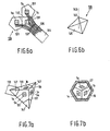
flexible foil 29 of an electrically insulating material, for example Kapton, which comprises threefirst parts 31 and onesecond part 33. On a main surface of thefoil 29 there are provided a number of electric conductor tracks 35 which are formed, for example from a thin layer of copper as is customary in the manufacture of printed circuit boards. Eachconductor track 35 starts on one of thefirst parts 31 and continues on thesecond part 33. Thefirst parts 31 have a square shape and thesecond part 33 is strip-shaped. On each of thefirst parts 31 there is mounted amagnetic sensor foil 29 is chosen so that the foil can be folded alongfolding lines 37, denoted by dashed lines, in such a manner that the threefirst parts 31 are situated in mutually perpendicular planes. The threefirst parts 31 then correspond to three side faces of a cube which adjoin the same comer point of the cube. Thefoil 29 can thus be folded about asupport 39 as shown in Fig. 4b. Thesupport 39 is shaped as a cube and may be made, for example of a suitable synthetic material. The cube may be hollow or solid. The corner point adjoined by said three side faces is denoted by thereference 41 in Fig. 4b and a body diagonal of the cube which extends through the relevant corner point and which is represented by a dash-dot line is denoted by thereference 43. The body diagonal encloses equal angles relative to the normals to said three side faces. - Fig. 5a is a perspective view of the semi-finished product obtained after
the folding of the
foil 29 about thesupport 39. The threefirst parts 31 contact three of the side faces of thesupport 39 and thesecond part 33 is folded back along a fourth side face. The conductor tracks 35 present on this part (not visible in Fig. 5a) can be connected, directly or via a connection cable (not shown), to the power supply circuit 9 and the signal processing circuit 11 (Fig. 2). If desired, components associated with these circuits may be mounted directly on thesecond part 33. The privileged directions ofmagnetization magnetic field sensors - Fig. 5b is a front view of a sensor part manufactured by using the semi-finished
product shown in Fig. 5a. To this end, the semi-finished product is arranged in a
magnetization coil 13 in such a manner that the body diagonal 43 (Fig. 4b) coincides with thecentral axis 27 which extends perpendicularly to the plane of drawing in Fig. 5b. The direction of an auxiliary magnetic field generated by themagnetization coil 13 and extending parallel to thecentral axis 27 thus encloses an angle of 57.4° relative to each of theprivileged directions magnetization coil 13 of the present embodiment is shaped as a right-angled prism having a cross-section in the form of an equilateral hexagon. As appears from Fig. 5b, the projection of the cubic assembly of magnetic field sensors on a plane perpendicular to the central axis 27 (the plane of drawing) is also shaped as an equilateral hexagon. Thus, this assembly almost completely fills the space within themagnetization coil 13, so that the dimensions and the weight of the sensor part are minimized. If slightly larger dimensions and higher weight are acceptable, evidently the magnetization coil may also have a different shape, for example the shape of a right-angled circular cylinder. Thesecond part 33 of thefoil 29, not being visible in Fig. 5b, then projects from themagnetization coil 13. - Fig. 6a is a plan view of a
flexible foil 129 which resembles thefoil 29 shown in Fig. 4a in many respects. The shape of thefirst parts 131 of thefoil 129, however, deviates from that of thefirst parts 31 of thefoil 29. Thefoil 129 is also provided with electric conductor tracks 135 which constitute connection conductors for themagnetic field sensors first parts 131. Thefoil 129 can be folded along dashedfolding lines 137 in such a manner that thefirst parts 131 are situated in mutually perpendicular planes which adjoin one another in one point. Thefoil 129 can thus be folded about asupport 139 which is shown in Fig. 6b and which is shaped as a pyramid having three mutually perpendicular faces which adjoin one another in a point 141 which constitutes the apex of the pyramid. From a point of view of geometry, these three faces correspond to three faces of a cube which adjoin one another in a comer point, the body diagonal of said cube being represented as a dash-dot line 143. The cube is cut off along aboundary face 145 which extends perpendicularly to the body diagonal 143 and constitutes the base of the pyramid. - Fig. 7a is a perspective view of a semi-finished product obtained by
folding the
foil 129 about thesupport 139 in the indicated manner. The threefirst parts 131 are arranged against the side faces of thesupport 139 and thesecond part 133 is folded back along thebase 145. The conductor tracks 135 provided on this part (not visible in Fig. 7a) can again be connected to the power supply circuit 9 and the signal processing circuit 11 (Fig. 2). The privileged directions ofmagnetization magnetic field sensors - Fig. 7b is a plan view of a sensor part manufactured by means of the
semi-finished product shown in Fig. 7a. To this end, the semi-finished product is arranged in
a
magnetization coil 13 in such a manner that the body diagonal 143 (Fig. 6b) coincides with thecentral axis 27 which extends perpendicularly to the plane of drawing in Fig. 7b. The direction of an auxiliary magnetic field generated by themagnetization coil 13 and extending parallel to thecentral axis 27, therefore, encloses an angle of 57.4° relative to each of theprivileged directions magnetization coil 13 of this embodiment is again shaped as a right-angled prism having a cross-section in the form of an equilateral hexagon. In order to make the semi-finished product shown in Fig. 7a suitable for such a coil it is desirable to cut off thepoints 147 of thesupport 139 which extend beyond thefirst parts 131 of thefoil 129. The support is thus shaped as a pyramid with truncated corner points. Like in the embodiment shown in Fig. 5b, however, other shapes of theirmagnetization coil 13 are also feasible, it being permissible for thesupport 139 to be shaped as shown in Fig. 6b. As has already been stated, because of the small dimensions of the sensor part, the described device is particularly suitable for use in a magnetic compass for a vehicle, for example a car, boat or aeroplane. Other feasible applications are, for example a compass which is built into a watch (notably the version of, for example Fig. 7 which is sensitive to two magnetic field components), or a self-contained compass for use as a sporting or car accessory. Further feasible applications are terrestrial field compensation control systems for high-resolution image monitors and traffic control systems (for example, sensors embedded in road surfaces).
Claims (7)
- A device for measuring magnetic fields, comprising an assembly of at least three magnetic field sensors (1), and a coil (13) which is formed as an electrical conductor which extends around a central axis (27) in a number of turns and which is arranged to generate an auxiliary magnetic field extending parallel to the central axis, characterized in that each of the magnetic field sensors (1) comprises several magnetoresistive sensor elements (3) which are situated in one plane and which have the same privileged directions of magnetization (5), said sensor elements being connected on the one side to a power circuit (9) and on the other side to a signal processing circuit (11), the privileged directions of magnetization of the sensor elements of different magnetic field sensors being different, the magnetic field sensors being arranged within the magnetization coil in such a manner that the angle enclosed by the central axis relative to the normal to the plane in which the sensor elements are situated is the same for each of the magnetic field sensors and that the auxiliary magnetic field at the area of the magnetic field sensors contains a component which extends parallel to the privileged directions of magnetization of the sensor elements of the relevant magnetic field sensor, and the direction of the auxiliary magnetic field encloses the same angle α relative to the privileged direction of magnetization (5a, 5b, 5c) of the sensor elements (3) of each of the magnetic field sensors (1a,1b,1c), where 0° < α < 90°.
- A device as claimed in Claim 1, characterized in that the assembly comprises three magnetic field sensors (1a, 1b, 1c) which are mounted on three mutually perpendicular surfaces of a support (39, 139), the plane of the sensor elements (3) of each of the magnetic field sensors extending parallel to one of the three surfaces, said support being arranged within the magnetization coil (13) in such a manner that the normals to the three said surfaces enclose equal angles relative to the central axis (27).
- A device as claimed in Claim 2, characterized in that the magnetic field sensors (1a, 1b, 1c) are mounted on first parts (31, 131) of a flexible foil (29, 129) of an electrically insulating material provided with electric conductor tracks (35, 135), the conductor tracks constituting connection conductors for connecting the sensor elements (3) to the power supply circuit (9) and the signal processing circuit (11), the foil being folded about the support (39, 139) in such a manner that the first parts of the foil are arranged against said surfaces.
- A device as claimed in Claim 3, characterized in that the foil (29, 129) also comprises a strip-shaped second part (33, 133) on which the conductor tracks (35, 135) continue and which projects from the magnetization coil (13).
- A device as claimed in any one of the Claims 2 to 4, characterized in that the support (39, 139) is shaped as at least a part of a cube, so that the three said surfaces adjoin the same corner point (41, 141) of the cube, the axis (27) of the magnetization coil (13) being coincident with a body diagonal (43, 143) of the cube which extends through said corner point.
- A device as claimed in Claim 5, characterized in that the support (39) is bounded, at the side situated opposite said corner point (141), by a boundary surface (145) which extends perpendicularly to said body diagonal (143).
- A device as claimed in Claim 5 or 6, characterized in that the magnetization coil (13) is shaped as a right-angled prism having a cross-section in the form of an equilateral hexagon.
Priority Applications (2)
| Application Number | Priority Date | Filing Date | Title |
|---|---|---|---|
| EP95907117A EP0696356B1 (en) | 1994-02-28 | 1995-02-10 | Device for measuring magnetic fields |
| EP02079951A EP1300687B1 (en) | 1994-02-28 | 1995-02-10 | Device for measuring magnetic fields |
Applications Claiming Priority (4)
| Application Number | Priority Date | Filing Date | Title |
|---|---|---|---|
| EP94200506 | 1994-02-28 | ||
| EP94200506 | 1994-02-28 | ||
| PCT/IB1995/000089 WO1995023342A1 (en) | 1994-02-28 | 1995-02-10 | Device for measuring magnetic fields |
| EP95907117A EP0696356B1 (en) | 1994-02-28 | 1995-02-10 | Device for measuring magnetic fields |
Related Child Applications (2)
| Application Number | Title | Priority Date | Filing Date |
|---|---|---|---|
| EP02079951A Division EP1300687B1 (en) | 1994-02-28 | 1995-02-10 | Device for measuring magnetic fields |
| EP02079951.6 Division-Into | 2002-11-26 |
Publications (2)
| Publication Number | Publication Date |
|---|---|
| EP0696356A1 EP0696356A1 (en) | 1996-02-14 |
| EP0696356B1 true EP0696356B1 (en) | 2004-01-07 |
Family
ID=8216672
Family Applications (2)
| Application Number | Title | Priority Date | Filing Date |
|---|---|---|---|
| EP02079951A Expired - Lifetime EP1300687B1 (en) | 1994-02-28 | 1995-02-10 | Device for measuring magnetic fields |
| EP95907117A Expired - Lifetime EP0696356B1 (en) | 1994-02-28 | 1995-02-10 | Device for measuring magnetic fields |
Family Applications Before (1)
| Application Number | Title | Priority Date | Filing Date |
|---|---|---|---|
| EP02079951A Expired - Lifetime EP1300687B1 (en) | 1994-02-28 | 1995-02-10 | Device for measuring magnetic fields |
Country Status (5)
| Country | Link |
|---|---|
| US (1) | US5689185A (en) |
| EP (2) | EP1300687B1 (en) |
| JP (1) | JP3542130B2 (en) |
| DE (1) | DE69532396T2 (en) |
| WO (1) | WO1995023342A1 (en) |
Cited By (2)
| Publication number | Priority date | Publication date | Assignee | Title |
|---|---|---|---|---|
| US7068030B2 (en) | 2004-04-28 | 2006-06-27 | Imation Corp. | Magnetic field strength detector |
| EP4361658A4 (en) * | 2021-06-25 | 2025-08-27 | Aichi Steel Corp | MAGNETISM MEASURING DEVICE |
Families Citing this family (27)
| Publication number | Priority date | Publication date | Assignee | Title |
|---|---|---|---|---|
| WO1996002847A1 (en) * | 1994-07-20 | 1996-02-01 | Honeywell Inc. | Miniature magnetometer |
| US6169254B1 (en) * | 1994-07-20 | 2001-01-02 | Honeywell, Inc. | Three axis sensor package on flexible substrate |
| JP2976924B2 (en) * | 1997-05-19 | 1999-11-10 | 日本電気株式会社 | Thin film temperature-sensitive resistance material and method of manufacturing the same |
| US6529114B1 (en) * | 1998-05-27 | 2003-03-04 | Honeywell International Inc. | Magnetic field sensing device |
| US6304082B1 (en) * | 1999-07-13 | 2001-10-16 | Honeywell International Inc. | Printed circuit boards multi-axis magnetometer |
| JP3872262B2 (en) * | 2000-01-25 | 2007-01-24 | セイコーインスツル株式会社 | Electronic compass and electronic watch with electronic compass |
| DE10014780B4 (en) * | 2000-03-27 | 2009-07-30 | Philips Intellectual Property & Standards Gmbh | MR angle sensor |
| DE10162752A1 (en) * | 2001-12-20 | 2003-07-03 | Philips Intellectual Property | Magnetoresistive sensor |
| US20040263935A1 (en) * | 2003-05-22 | 2004-12-30 | Heinz Keiser | Scanner |
| JP3781056B2 (en) * | 2003-07-18 | 2006-05-31 | 愛知製鋼株式会社 | 3D magnetic orientation sensor and magneto-impedance sensor element |
| KR20060079219A (en) * | 2003-09-16 | 2006-07-05 | 코닌클리즈케 필립스 일렉트로닉스 엔.브이. | Electronic devices, manufacturing methods and semifinished products thereof |
| US7095226B2 (en) * | 2003-12-04 | 2006-08-22 | Honeywell International, Inc. | Vertical die chip-on-board |
| US7301332B2 (en) * | 2005-10-06 | 2007-11-27 | Biosense Webster, Inc. | Magnetic sensor assembly |
| DE102007021320A1 (en) * | 2007-05-07 | 2008-11-20 | Infineon Technologies Ag | Sensor for detecting a magnetic field direction, magnetic field direction detection, method for producing magnetic field sensors and write-in device for the production of magnetic field sensors |
| US7994773B2 (en) | 2008-07-11 | 2011-08-09 | Data Security, Inc. | Apparatus and method for in-field magnetic measurements |
| FR2955942B1 (en) * | 2010-01-29 | 2013-01-04 | Centre Nat Rech Scient | INTEGRATED MAGNETOMETER AND METHOD FOR MANUFACTURING THE SAME |
| US8018229B1 (en) | 2010-04-22 | 2011-09-13 | Honeywell International Inc. | Structure and method for flex circuit on a chip |
| EP2551691A1 (en) * | 2011-07-27 | 2013-01-30 | Paul Scherrer Institut | A method for manufacturing a Hall sensor assembly and a Hall sensor assembly |
| JP5699857B2 (en) * | 2011-08-22 | 2015-04-15 | 株式会社デンソー | Magnetic sensor device and manufacturing method thereof |
| US8947082B2 (en) | 2011-10-21 | 2015-02-03 | University College Cork, National University Of Ireland | Dual-axis anisotropic magnetoresistive sensors |
| US9166598B1 (en) | 2012-05-08 | 2015-10-20 | Altera Corporation | Routing and programming for resistive switch arrays |
| EP2883066B1 (en) * | 2012-08-07 | 2018-04-04 | Scott Technology NZ Limited | Improved magnetic field control |
| US9664747B2 (en) * | 2012-08-28 | 2017-05-30 | Apple Inc. | Electronic devices with magnetic sensors |
| WO2014114401A1 (en) * | 2013-01-24 | 2014-07-31 | Paul Scherrer Institut | A method for manufacturing a hall sensor assembly and a hall sensor assembly |
| US20150309125A1 (en) * | 2013-04-29 | 2015-10-29 | Labsys Llc | Monolithic Three-Axis Magnetometer |
| US9995600B2 (en) | 2015-09-01 | 2018-06-12 | General Electric Company | Multi-axis magneto-resistance sensor package |
| JP7347397B2 (en) * | 2020-10-28 | 2023-09-20 | Tdk株式会社 | Magnetic sensor and its manufacturing method |
Family Cites Families (7)
| Publication number | Priority date | Publication date | Assignee | Title |
|---|---|---|---|---|
| NL7611522A (en) * | 1976-10-19 | 1978-04-21 | Philips Nv | MAGNETO RESISTANCE READING HEAD WITH THERMAL NOISE REDUCTION. |
| US4296377A (en) * | 1978-03-27 | 1981-10-20 | Sony Corporation | Magnetic signal field sensor that is substantially immune to angular displacement relative to the signal field |
| CH675916A5 (en) * | 1987-05-11 | 1990-11-15 | Wild Leitz Ag | |
| NL8900750A (en) * | 1989-03-28 | 1990-10-16 | Philips Nv | DEVICE FOR MEASURING A RELATIVE MOVEMENT. |
| EP0411971B1 (en) * | 1989-07-24 | 1994-08-24 | CLAUSIN, Jacques | Arrangment for measuring the temporal variations of the three components of the local magnetic field and orientation of the arrangment with respect to the local vertical |
| DE4003161A1 (en) * | 1990-02-03 | 1991-08-08 | Standard Elektrik Lorenz Ag | Magnetic field sensor with magnetic field dependent resistances - has resistance strips separated by insulating non=magnetic layer from each other so longitudinal axes run at right angles |
| US5255442A (en) * | 1991-12-20 | 1993-10-26 | Donnelly Corporation | Vehicle compass with electronic sensor |
-
1995
- 1995-02-10 JP JP52222995A patent/JP3542130B2/en not_active Expired - Fee Related
- 1995-02-10 DE DE69532396T patent/DE69532396T2/en not_active Expired - Lifetime
- 1995-02-10 EP EP02079951A patent/EP1300687B1/en not_active Expired - Lifetime
- 1995-02-10 WO PCT/IB1995/000089 patent/WO1995023342A1/en not_active Ceased
- 1995-02-10 EP EP95907117A patent/EP0696356B1/en not_active Expired - Lifetime
- 1995-02-16 US US08/389,361 patent/US5689185A/en not_active Expired - Lifetime
Cited By (3)
| Publication number | Priority date | Publication date | Assignee | Title |
|---|---|---|---|---|
| US7068030B2 (en) | 2004-04-28 | 2006-06-27 | Imation Corp. | Magnetic field strength detector |
| EP4361658A4 (en) * | 2021-06-25 | 2025-08-27 | Aichi Steel Corp | MAGNETISM MEASURING DEVICE |
| US12578495B2 (en) | 2021-06-25 | 2026-03-17 | Aichi Steel Corporation | Sensor block for magnetism measurement |
Also Published As
| Publication number | Publication date |
|---|---|
| WO1995023342A1 (en) | 1995-08-31 |
| DE69532396T2 (en) | 2004-12-09 |
| US5689185A (en) | 1997-11-18 |
| JP3542130B2 (en) | 2004-07-14 |
| JPH08510059A (en) | 1996-10-22 |
| EP1300687A2 (en) | 2003-04-09 |
| EP0696356A1 (en) | 1996-02-14 |
| EP1300687A3 (en) | 2008-03-26 |
| DE69532396D1 (en) | 2004-02-12 |
| EP1300687B1 (en) | 2011-09-21 |
Similar Documents
| Publication | Publication Date | Title |
|---|---|---|
| US5689185A (en) | Compact device for measuring magnetic fields having magnetoresistors and an auxiliary magnetic field generator | |
| EP0696357B1 (en) | Device for measuring magnetic fields | |
| EP2671091B1 (en) | Magnetic field sensing device | |
| JP5362115B2 (en) | Magnetic field sensor | |
| US7298140B2 (en) | Three-dimensional magnetic direction sensor, and magneto-impedance sensor element | |
| EP2413153B9 (en) | Magnetic detection device | |
| US7642768B1 (en) | Current sensor having field screening arrangement including electrical conductors sandwiching magnetic permeability layer | |
| US6556007B1 (en) | Bearing sensor having magneto resistive elements | |
| EP1293792B1 (en) | Magnetic detection element utilizing magneto-impedance effect, production method of the element, and portable equipment using the element | |
| US20120146620A1 (en) | Current sensor | |
| JPH08503778A (en) | Magnetic field sensor comprising magnetic reversal conductor and one or more magnetoresistive resistors | |
| JP6320515B2 (en) | Magnetic field sensor device | |
| JP2000249725A (en) | Manufacture of current sensor | |
| WO2009084433A1 (en) | Magnetic sensor and magnetic sensor module | |
| EP3477322B1 (en) | Magnetic sensor with integrated solenoid | |
| JP2003315376A (en) | Current sensor | |
| JP2022189812A (en) | Current sensor comprising magnetic field sensor in v-shaped arrangement | |
| EP0910802A2 (en) | Magnetic field sensor comprising a wheatstone bridge | |
| CN121114538A (en) | Current sensor | |
| US5601367A (en) | Temperature sensor for sensing temperature in a magnetic field | |
| EP3779487B1 (en) | Assembly and method for determining the strength of a magnetic stray field | |
| CN101611327A (en) | Have the flip coil of combination and the MR magnetometer of compensating coil | |
| CA2267299A1 (en) | Magnetic impedance effect device | |
| JP2576763B2 (en) | Ferromagnetic magnetoresistive element |
Legal Events
| Date | Code | Title | Description |
|---|---|---|---|
| PUAI | Public reference made under article 153(3) epc to a published international application that has entered the european phase |
Free format text: ORIGINAL CODE: 0009012 |
|
| AK | Designated contracting states |
Kind code of ref document: A1 Designated state(s): DE FR GB IT SE |
|
| 17P | Request for examination filed |
Effective date: 19960229 |
|
| 17Q | First examination report despatched |
Effective date: 20020110 |
|
| GRAH | Despatch of communication of intention to grant a patent |
Free format text: ORIGINAL CODE: EPIDOS IGRA |
|
| GRAH | Despatch of communication of intention to grant a patent |
Free format text: ORIGINAL CODE: EPIDOS IGRA |
|
| GRAA | (expected) grant |
Free format text: ORIGINAL CODE: 0009210 |
|
| AK | Designated contracting states |
Kind code of ref document: B1 Designated state(s): DE FR GB IT SE |
|
| REG | Reference to a national code |
Ref country code: GB Ref legal event code: FG4D |
|
| REF | Corresponds to: |
Ref document number: 69532396 Country of ref document: DE Date of ref document: 20040212 Kind code of ref document: P |
|
| REG | Reference to a national code |
Ref country code: SE Ref legal event code: TRGR |
|
| ET | Fr: translation filed | ||
| PLBE | No opposition filed within time limit |
Free format text: ORIGINAL CODE: 0009261 |
|
| STAA | Information on the status of an ep patent application or granted ep patent |
Free format text: STATUS: NO OPPOSITION FILED WITHIN TIME LIMIT |
|
| 26N | No opposition filed |
Effective date: 20041008 |
|
| REG | Reference to a national code |
Ref country code: GB Ref legal event code: 732E |
|
| REG | Reference to a national code |
Ref country code: GB Ref legal event code: 732E |
|
| REG | Reference to a national code |
Ref country code: FR Ref legal event code: TP |
|
| REG | Reference to a national code |
Ref country code: FR Ref legal event code: GC |
|
| REG | Reference to a national code |
Ref country code: GB Ref legal event code: 732E Free format text: REGISTERED BETWEEN 20090618 AND 20090624 |
|
| REG | Reference to a national code |
Ref country code: FR Ref legal event code: GC |
|
| PG25 | Lapsed in a contracting state [announced via postgrant information from national office to epo] |
Ref country code: IT Free format text: LAPSE BECAUSE OF NON-PAYMENT OF DUE FEES Effective date: 20080210 |
|
| PGFP | Annual fee paid to national office [announced via postgrant information from national office to epo] |
Ref country code: SE Payment date: 20090206 Year of fee payment: 15 |
|
| EUG | Se: european patent has lapsed | ||
| REG | Reference to a national code |
Ref country code: GB Ref legal event code: 732E Free format text: REGISTERED BETWEEN 20101007 AND 20101013 |
|
| REG | Reference to a national code |
Ref country code: FR Ref legal event code: GC |
|
| REG | Reference to a national code |
Ref country code: GB Ref legal event code: 732E Free format text: REGISTERED BETWEEN 20111013 AND 20111019 |
|
| REG | Reference to a national code |
Ref country code: FR Ref legal event code: AU Effective date: 20120126 |
|
| REG | Reference to a national code |
Ref country code: GB Ref legal event code: 732E Free format text: REGISTERED BETWEEN 20120315 AND 20120321 |
|
| PGFP | Annual fee paid to national office [announced via postgrant information from national office to epo] |
Ref country code: IT Payment date: 20120121 Year of fee payment: 18 |
|
| REG | Reference to a national code |
Ref country code: GB Ref legal event code: 732E Free format text: REGISTERED BETWEEN 20120705 AND 20120711 |
|
| PG25 | Lapsed in a contracting state [announced via postgrant information from national office to epo] |
Ref country code: SE Free format text: LAPSE BECAUSE OF NON-PAYMENT OF DUE FEES Effective date: 20100211 |
|
| REG | Reference to a national code |
Ref country code: GB Ref legal event code: 732E Free format text: REGISTERED BETWEEN 20120927 AND 20121003 |
|
| REG | Reference to a national code |
Ref country code: FR Ref legal event code: AU Effective date: 20121009 |
|
| PGFP | Annual fee paid to national office [announced via postgrant information from national office to epo] |
Ref country code: FR Payment date: 20130408 Year of fee payment: 19 |
|
| REG | Reference to a national code |
Ref country code: FR Ref legal event code: AU Effective date: 20130402 |
|
| REG | Reference to a national code |
Ref country code: GB Ref legal event code: 732E Free format text: REGISTERED BETWEEN 20130606 AND 20130612 |
|
| PGFP | Annual fee paid to national office [announced via postgrant information from national office to epo] |
Ref country code: DE Payment date: 20140122 Year of fee payment: 20 |
|
| PGFP | Annual fee paid to national office [announced via postgrant information from national office to epo] |
Ref country code: GB Payment date: 20140127 Year of fee payment: 20 |
|
| REG | Reference to a national code |
Ref country code: FR Ref legal event code: ST Effective date: 20141031 |
|
| PG25 | Lapsed in a contracting state [announced via postgrant information from national office to epo] |
Ref country code: FR Free format text: LAPSE BECAUSE OF NON-PAYMENT OF DUE FEES Effective date: 20140228 |
|
| REG | Reference to a national code |
Ref country code: DE Ref legal event code: R071 Ref document number: 69532396 Country of ref document: DE |
|
| REG | Reference to a national code |
Ref country code: GB Ref legal event code: PE20 Expiry date: 20150209 |
|
| PG25 | Lapsed in a contracting state [announced via postgrant information from national office to epo] |
Ref country code: GB Free format text: LAPSE BECAUSE OF EXPIRATION OF PROTECTION Effective date: 20150209 |
|
| PG25 | Lapsed in a contracting state [announced via postgrant information from national office to epo] |
Ref country code: IT Free format text: LAPSE BECAUSE OF NON-PAYMENT OF DUE FEES Effective date: 20140210 |