EP0695574A1 - Gas separation with fractional purge for pre- or post-purification - Google Patents
Gas separation with fractional purge for pre- or post-purification Download PDFInfo
- Publication number
- EP0695574A1 EP0695574A1 EP95112219A EP95112219A EP0695574A1 EP 0695574 A1 EP0695574 A1 EP 0695574A1 EP 95112219 A EP95112219 A EP 95112219A EP 95112219 A EP95112219 A EP 95112219A EP 0695574 A1 EP0695574 A1 EP 0695574A1
- Authority
- EP
- European Patent Office
- Prior art keywords
- gas
- membrane
- permeate
- separation membrane
- purge
- Prior art date
- Legal status (The legal status is an assumption and is not a legal conclusion. Google has not performed a legal analysis and makes no representation as to the accuracy of the status listed.)
- Granted
Links
- 238000000926 separation method Methods 0.000 title claims abstract description 115
- 238000010926 purge Methods 0.000 title claims abstract description 83
- 238000000746 purification Methods 0.000 title claims abstract description 24
- 239000012528 membrane Substances 0.000 claims abstract description 230
- 239000012466 permeate Substances 0.000 claims abstract description 95
- 238000011144 upstream manufacturing Methods 0.000 claims abstract description 8
- 230000003247 decreasing effect Effects 0.000 claims abstract description 4
- 238000010981 drying operation Methods 0.000 claims abstract 5
- 239000007789 gas Substances 0.000 claims description 121
- IJGRMHOSHXDMSA-UHFFFAOYSA-N Atomic nitrogen Chemical compound N#N IJGRMHOSHXDMSA-UHFFFAOYSA-N 0.000 claims description 80
- 239000000047 product Substances 0.000 claims description 57
- 229910052757 nitrogen Inorganic materials 0.000 claims description 40
- 238000000034 method Methods 0.000 claims description 17
- 230000008569 process Effects 0.000 claims description 17
- 238000011403 purification operation Methods 0.000 claims description 17
- QVGXLLKOCUKJST-UHFFFAOYSA-N atomic oxygen Chemical compound [O] QVGXLLKOCUKJST-UHFFFAOYSA-N 0.000 claims description 16
- 238000001035 drying Methods 0.000 claims description 16
- 239000001301 oxygen Substances 0.000 claims description 16
- 229910052760 oxygen Inorganic materials 0.000 claims description 16
- 238000004519 manufacturing process Methods 0.000 claims description 8
- 238000004064 recycling Methods 0.000 claims 2
- XLYOFNOQVPJJNP-UHFFFAOYSA-N water Chemical compound O XLYOFNOQVPJJNP-UHFFFAOYSA-N 0.000 description 7
- 230000008901 benefit Effects 0.000 description 4
- 230000000274 adsorptive effect Effects 0.000 description 3
- 238000013459 approach Methods 0.000 description 3
- 230000007423 decrease Effects 0.000 description 3
- 239000000463 material Substances 0.000 description 3
- 238000001179 sorption measurement Methods 0.000 description 3
- CURLTUGMZLYLDI-UHFFFAOYSA-N Carbon dioxide Chemical compound O=C=O CURLTUGMZLYLDI-UHFFFAOYSA-N 0.000 description 2
- UFHFLCQGNIYNRP-UHFFFAOYSA-N Hydrogen Chemical compound [H][H] UFHFLCQGNIYNRP-UHFFFAOYSA-N 0.000 description 2
- 238000006243 chemical reaction Methods 0.000 description 2
- 230000006835 compression Effects 0.000 description 2
- 238000007906 compression Methods 0.000 description 2
- 229930195733 hydrocarbon Natural products 0.000 description 2
- 150000002430 hydrocarbons Chemical class 0.000 description 2
- 239000001257 hydrogen Substances 0.000 description 2
- 229910052739 hydrogen Inorganic materials 0.000 description 2
- 239000000203 mixture Substances 0.000 description 2
- 238000012545 processing Methods 0.000 description 2
- 238000011084 recovery Methods 0.000 description 2
- 230000009467 reduction Effects 0.000 description 2
- 239000004215 Carbon black (E152) Substances 0.000 description 1
- 238000012356 Product development Methods 0.000 description 1
- 230000002745 absorbent Effects 0.000 description 1
- 239000002250 absorbent Substances 0.000 description 1
- 239000003463 adsorbent Substances 0.000 description 1
- 238000007605 air drying Methods 0.000 description 1
- 229910002092 carbon dioxide Inorganic materials 0.000 description 1
- 239000001569 carbon dioxide Substances 0.000 description 1
- 230000008859 change Effects 0.000 description 1
- 230000000052 comparative effect Effects 0.000 description 1
- 239000002131 composite material Substances 0.000 description 1
- 238000009833 condensation Methods 0.000 description 1
- 230000005494 condensation Effects 0.000 description 1
- 238000005260 corrosion Methods 0.000 description 1
- 230000007797 corrosion Effects 0.000 description 1
- 238000011161 development Methods 0.000 description 1
- 230000018109 developmental process Effects 0.000 description 1
- 230000000694 effects Effects 0.000 description 1
- 238000013178 mathematical model Methods 0.000 description 1
- 230000007246 mechanism Effects 0.000 description 1
- 238000012986 modification Methods 0.000 description 1
- 230000004048 modification Effects 0.000 description 1
- 238000005057 refrigeration Methods 0.000 description 1
- 230000001172 regenerating effect Effects 0.000 description 1
- 230000008929 regeneration Effects 0.000 description 1
- 238000011069 regeneration method Methods 0.000 description 1
- 238000006467 substitution reaction Methods 0.000 description 1
Images
Classifications
-
- B—PERFORMING OPERATIONS; TRANSPORTING
- B01—PHYSICAL OR CHEMICAL PROCESSES OR APPARATUS IN GENERAL
- B01D—SEPARATION
- B01D53/00—Separation of gases or vapours; Recovering vapours of volatile solvents from gases; Chemical or biological purification of waste gases, e.g. engine exhaust gases, smoke, fumes, flue gases, aerosols
- B01D53/26—Drying gases or vapours
- B01D53/268—Drying gases or vapours by diffusion
-
- B—PERFORMING OPERATIONS; TRANSPORTING
- B01—PHYSICAL OR CHEMICAL PROCESSES OR APPARATUS IN GENERAL
- B01D—SEPARATION
- B01D53/00—Separation of gases or vapours; Recovering vapours of volatile solvents from gases; Chemical or biological purification of waste gases, e.g. engine exhaust gases, smoke, fumes, flue gases, aerosols
- B01D53/22—Separation of gases or vapours; Recovering vapours of volatile solvents from gases; Chemical or biological purification of waste gases, e.g. engine exhaust gases, smoke, fumes, flue gases, aerosols by diffusion
- B01D53/225—Multiple stage diffusion
- B01D53/226—Multiple stage diffusion in serial connexion
Definitions
- This invention relates to membrane gas separation operations. More particularly, it relates to the purge requirements of pre or post gas separation purification operations.
- Permeable membrane processes and systems have been proposed and used increasingly for significant gas separation operations.
- nitrogen by air separation, for example, feed air is brought into contact with the surface of the membrane, and oxygen, as the more readily permeable component of air, selectively passes through the membrane while nitrogen, the less readily permeable component of air, is withdrawn from the membrane systems as a non- permeable product stream.
- Conventional membrane systems typically produce nitrogen having purity levels of up to about 99.5%. Higher nitrogen purities can be achieved if a post-purification feature is employed.
- Such processing may also include the use of a countercurrent membrane feed air or product dryer with permeate gas from an air separation membrane being employed as purge gas in the membrane dryer.
- a source of clean, dry compressed air is also desired to prevent corrosion and condensation in instrumentation, piping, pneumatic tools, ventilators and other plant operations.
- separate adsorptive or refrigerative dryers have typically been utilized.
- Such units tend to have significant product losses, due to purge and blowdown steps, or generally require a significant expenditure of added energy., e.g. for regeneration or refrigeration.
- stage cuts i.e., the permeate to feed flow ratio
- the permeate to feed flow ratio on the order of 10% to 30% might be required to achieve the dew point typically provided by adsorptive or refrigerative dryers.
- the substitution of crossflow-type membrane dryers to produce clean, dry compressed air is not economically attractive.
- a purge stream for pre- or post-air or other gas separation purification operations.
- the purge stream is commonly obtained from the permeate gas removed from the modules of one of the membrane air separation stages.
- This pressure is usually obtained by back pressurizing the permeate side of the air separation membrane modules in one of the membrane stages.
- This increased back pressure of the membrane modules reduces the available pressure ratio between the higher feed air pressure on the feed, or non-permeate, side of the membrane modules and the lower pressure on the permeate side of said membrane modules.
- This approach necessitates an increase in the membrane surface area and in the power required to perform the desired air separation operation. However, this approach eliminates any need for extra compression equipment or blowers.
- patent also discloses a membrane process for the co-production of dry air and nitrogen wherein the first stage or second stage air separation membrane permeate stream is used to purge a membrane air dryer.
- European patent application 0 430 304 likewise describes the operation of a membrane air separation system with a membrane dryer positioned in the feed air stream, wherein the permeate gas from the air separation membrane modules are passed through outlet 24 and conduit 26 to the permeate side of membranes 8 in housing vessel 6 for use as purge gas to facilitate the drying of the feed air passing therethrough to membrane air separation modules 20 in vessel 16.
- 4,931,070 discloses a two-stage membrane air separation system containing first stage membrane 4 and second stage membrane 7, wherein membrane dryer 16 used to dry the high purity nitrogen product from the membrane air separation-deoxo purification system. Permeate gas withdrawn from the overall second stage membrane modules 7 is used as purge gas on the permeate side of said membrane dryer 16.
- the total permeate gas flow removed from a membrane air separation stage is utilized, or is available for use, as purge gas for the membrane dryer.
- the full amount of permeate gas from a membrane air separation system, or a stage thereof may not be required for membrane dryer purge purposes.
- the availability of the total permeate flow from a membrane air separation system, or a stage thereof is commonly available in ordinary commercial practice.
- the purge stream for purging pre- or post-purification operations associated with a membrane air or other gas separation system is taken from only a fraction of the modules of a membrane air or other gas separation stage.
- only a portion of the modules in a stage are back pressured on the permeate side thereof and thus suffer reduced efficiency.
- the efficiency of the overall membrane air separation is thereby increased over that of systems in which the full permeate flow of the stage is back pressured on the permeate side and is available for purge purposes.
- the objects of the invention are accomplished by carrying out membrane air or other gas separation operations, with pre- or post-air or other gas separation purification operations, utilizing purge gas taken from only a fraction of the modules in a membrane air or other gas separation stage for purge purposes in the pre- or post-purification operation.
- the full permeate flow from said membrane stage is not employed for purge purposes, contrary to conventional practice.
- only a fraction of the membrane modules in the stage supplying purge gas needs to be back pressured on the permeate side and thus suffer reduced performance efficiency.
- the remaining membrane bundles in the particular stage, not required for such purge purposes are not back pressured, and do not undergo such reduced efficiency.
- the overall power and capital costs associated with the particular membrane stage are advantageously reduced as compared to conventional practice.
- the process recovery and membrane surface area requirements are a function of the pressure ratio between the higher pressure non-permeate stream and the lower pressure permeate stream.
- this pressure ratio is caused to decrease, as by back pressurizing on the permeate side, recovery decreases, and the area requirements increase.
- the negative impact of back-pressuring the modules to provide the desired purge gas flow for pre- or post- purification operations is effectively decreased. This leads to desirably lower power and surface area costs, on the order of 1-5%, than pertain when all of the modules of the pertinent membrane stage have increased back pressure imposed thereon.
- the invention achieves a desired reduction in back pressure, and in membrane air or other gas separation efficiency loss, for a membrane product system that utilizes permeate therefrom for purge purposes in another system for pre-purification of the feed air or other gas to the membrane air separation system or for post-purification of the nitrogen or other product from said separation system.
- desired results are obtained by utilizing only a portion of the membrane modules in a particular membrane stage for purge purposes instead of having the full permeate flow from that stage available for such purge purposes.
- the portion of the modules needed to provide the amount of permeate from a given membrane stage to provide purge gas to a membrane dryer(s) or absorbent beds used for purification will generally be on the order of from about 10% to about 80% of the membrane modules in a stage. It will be understood that it is desirable to utilize the minimum percentage of modules that generates sufficient flow for the desired purge purposes. In addition, by reducing the purge flow to that required for pre- or post-purification, and not using the whole available permeate stream, the pressure drop through the pre- or post-purification device is reduced.
- the permeation rate through a membrane gas separation module and hence the performance efficiency of the module, depend on several process and system variables, such as the composition and properties of the membrane material, the configuration of the membrane air separation module, the desired product properties, the condition of the feed air or other gas to the membrane separation system, and the temperature and pressure of the membrane separation operation. Under given operating conditions, the efficiency depends upon the pressure ratio of the feed gas to the permeate in the module.
- the novel approach of the invention enables the overall pressure ratio to be increased, and overall performance efficiency to be enhanced, with lower power and surface area requirements, than has heretofore been possible in conventional practice where the full permeate flow from a stage is made available for purge purposes and said back-pressuring on the permeate side is needed to facilitate purge in pre- or post-purification operations.
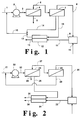
- Fig. 1 of the drawings with respect to the drawings with respect to a particular example wherein permeate from the modules of the second stage of an air separation membrane nitrogen plant is used to provide purge for the post-treatment drying of the high purity product nitrogen from said air separation membrane plant and subsequent deoxo purification.
- the plant is operated at 100°F and 125 psig.
- the oxygen/nitrogen selectivity of the air separation membrane is 4.64, and the permeation rate of the more selectively permeable oxygen component of the feed air is 8.35 x 10⁵ Barrer/cm.
- the nitrogen product purity exiting the membrane air separation system is 99% and the additional back pressure needed to purge the membrane dryer is 4 psig.
- the membrane surface area is equally distributed between the two stages of the membrane air separation system.
- feed air is passed in line 1 to feed air compressor 2 from which compressed feed air is passed in line 3 to first stage air separation membrane 4 of a two-stage air separation system.
- the more readily permeable oxygen component of the feed air is selectively permeated therein and is withdrawn as an oxygen-enriched stream from the permeate side of said membrane 4 through line 5, typically at 0 psig, for discharge from the system.
- the non-permeate gas i.e. partially purified nitrogen, is withdrawn from the non-permeate side of said membrane 4 through line 6 for passage to second stage air separation membrane 7.
- the less readily permeable nitrogen product is recovered from the non-permeate side of said membrane 7 through line 8.
- the nitrogen product is passed in said line 8 to a conventional deoxo unit 9. Hydrogen or a hydrocarbon is added to deoxo unit 9 through line 10 for reaction with said residual oxygen to form water vapor.
- the thus-purified nitrogen is passed from deoxo unit 9 through line 11 to the feed, i.e. non-permeate, side of membrane dryer 12. Dry, high purity nitrogen product is recovered from the non-permeate side of said membrane dryer through line 13.
- Permeate from second stage air separation membrane 7 that is not required for providing purge to membrane dryer 12 is passed from a portion of the modules in said membrane 7, typically at 0 psig, through lines 14 and 15 for recycle to line 1 for passage, with additional quantities of feed air, to feed air compressor 2 and first stage air separation membrane 4.
- the permeate from the remaining portion of modules in said membrane 7 is to be used for purge purposes in said membrane dryer 12. Accordingly, the permeate from the remaining portion of modules from membrane 7 is separately removed therefrom through line 16.
- the permeate from said remaining portion of modules is back pressured automatically by a self-regulating mechanism, so as to be withdrawn at a pressure suitable for purge purposes, and the pressure drop through the membrane dryer, e.g.
- Purge gas from line 16 is passed, at said suitable purge pressure, to the permeate side of membrane dryer 12 to facilitate the permeation of water vapor through the membrane for the desired drying of the high purity nitrogen product therein.
- Said purge gas and water vapor containing permeate gas is withdrawn from membrane dryer 12 on the permeate side thereof through line 17 and is desirably recycled, together with the permeate in line 14, to line 1 for processing with additional quantities of feed air passing therein to feed air compressor 2.
- first stage membrane 4 and second stage membrane 7 were operated, with no additional back pressure imposed in second stage membrane 7, to produce 10,000 cfh (cubic feet per hour) of nitrogen product, a total membrane surface area of 14,260 ft2, and an air feed flow of 36,120 cfh, would be required. If, on the other hand, all of the modules of second stage membrane 7 have the additional 4 psi back pressure imposed thereon, as in conventional practice where the full permeate flow is withdrawn without separation, the required membrane surface area is increased to 15,270 ft2, and the feed air flow required is increased to 37,360 cfh.
- back pressure is required in order to enable permeate from the air separation membrane system to be desirably used on the permeate side of the downstream membrane dryer without the need to use added compression equipment.
- the membrane surface area of the two-stage membrane air separation system needed to achieve the desired nitrogen product production is 3.2% less than in the conventional practice wherein all of the modules of second stage membrane 7 have additional back pressure imposed thereon so as to be available for purge purposes.
- the feed air flow is 1.5% lower for the embodiment of the invention in which only 50% of the modules in second stage membrane 7 are subjected to additional back pressure than the feed air requirements in said conventional practice.
- the magnitude of the change in efficiency achieved in the practice of the invention is a function of the number of modules back pressured, the magnitude of the back pressure, the product purity desired and the plant operating conditions.
- the number of modules that are back pressured is a function of the required purge flow rate. It will be seen that the advantages achieved by the practice of the invention are greater when only a small amount of purge is required. This minimizes the number of modules that must be back pressured in a membrane stage, thus increasing the plant efficiency. Reductions in efficiency have a greater impact when high purity product, e.g. greater than 99%, is being produced. Thus, the invention is most advantageous when higher product purities are being produced by the membrane air separation system.
- Fig. 2 of the drawings illustrates another embodiment in which a portion of the first stage permeate gas is used for purge purposes.
- Feed air is introduced to the system through line 21 and is passed to feed air compressor 22 from which compressed feed air is passed in line 23 to first stage air separation membrane 24 of a two-stage membrane air separation system.
- first stage air separation membrane 24 of a two-stage membrane air separation system.
- the more readily permeable oxygen component of the feed air is selectively permeated therein.
- only a portion of said first stage permeate is withdrawn from the permeate side of membrane 24 through line 25 for discharge from the system.
- the remaining portion of said first side permeate is separately withdrawn through line 26 for use as purge gas in the downstream dryer referred to below.
- Non-permeate gas is passed in line 27 from first stage membrane 24 to the feed, i.e. non-permeate, side of second stage membrane 28. Permeate removed from said membrane 28 is recycled in line 29 to line 21 for passage, with additional quantities of feed air, to feed air compressor 22 and first stage membrane 24.
- Non-permeate gas from membrane 28, i.e. low purity nitrogen product is passed in line 30 to deoxo unit 31 for reaction therein of residual amounts of oxygen in the nitrogen product with hydrogen introduced to said deoxo unit 31 through line 32.
- the thus-purified nitrogen product is passed from the deoxo unit in line 33 to membrane dryer 34, from which dry, high purity nitrogen product is recovered through line 35.
- the portion of the permeate from first stage air separation membrane 24 that is separately removed therefrom through line 26 is back pressured and is passed to the permeate side of membrane dryer 34.
- Such purge gas, and the water vapor-containing permeate from said membrane dryer 34 are discharged from the system through line 36.
- a blower or compressor unit could be used in the flow line of the fractional portion of the permeate separately withdrawn for purge purposes, as an alternative to back pressuring the modules from which said permeate is taken.
- the purification operations can be carried out by means of any suitable purification system, for example, a membrane purification system, such as the membrane dryer used in the illustrative examples, or a suitable adsorption system, such as a pressure swing adsorption (PSA) system or a thermal swing adsorption (TSA) system can be used for such purification purposes.
- PSA pressure swing adsorption
- TSA thermal swing adsorption
- the purification operation can either be downstream of the membrane air separation system, as in the illustrated examples, or upstream thereof, as for feed air drying, including embodiments such as in said Prasad patent, U.S. 5,169,412, wherein both clean dry air and high purity nitrogen product is desired.
- a purification operation upstream of the membrane gas separation system can be used for other purposes, such as for the removal of carbon dioxide or hydrocarbons from feed air or other gas if a membrane system used for gas separation is sensitive thereto.
- the advantageous benefits of the invention are achieved by the fractional purge feature thereof wherein only a portion, and not all, of the permeate of a membrane air separation stage is withdrawn for purge purposes.
- the invention represents a highly significant advance in the membrane air separation art, enabling the efficiency thereof to be enhanced, with lower power and membrane surface area requirements, than previously encountered in conventional practice.
Landscapes
- Chemical & Material Sciences (AREA)
- Engineering & Computer Science (AREA)
- Analytical Chemistry (AREA)
- General Chemical & Material Sciences (AREA)
- Oil, Petroleum & Natural Gas (AREA)
- Chemical Kinetics & Catalysis (AREA)
- Separation Using Semi-Permeable Membranes (AREA)
- Drying Of Gases (AREA)
Abstract
Description
- This invention relates to membrane gas separation operations. More particularly, it relates to the purge requirements of pre or post gas separation purification operations.
- Permeable membrane processes and systems have been proposed and used increasingly for significant gas separation operations. In the production of nitrogen by air separation, for example, feed air is brought into contact with the surface of the membrane, and oxygen, as the more readily permeable component of air, selectively passes through the membrane while nitrogen, the less readily permeable component of air, is withdrawn from the membrane systems as a non- permeable product stream. Conventional membrane systems typically produce nitrogen having purity levels of up to about 99.5%. Higher nitrogen purities can be achieved if a post-purification feature is employed. Such processing may also include the use of a countercurrent membrane feed air or product dryer with permeate gas from an air separation membrane being employed as purge gas in the membrane dryer. In some industrial operations, a source of clean, dry compressed air is also desired to prevent corrosion and condensation in instrumentation, piping, pneumatic tools, ventilators and other plant operations. For such latter purposes, separate adsorptive or refrigerative dryers have typically been utilized. Such units, however, tend to have significant product losses, due to purge and blowdown steps, or generally require a significant expenditure of added energy., e.g. for regeneration or refrigeration.
- The ability of various membrane materials to permeate water vapor is well known in the art. Thus, a membrane system utilizing such a material could be used to replace the function of the adsorptive (or regenerative) dryer for producing clean, dry air for a variety of purposes. However, many practical commercial asymmetric and composite-type membranes have been characterized by the crossflow permeation model performance, wherein the composition of the bulk gas on the permeate side of the membrane has little effect on the permeation rates achieved. Accordingly, the removal of water vapor in compressed air streams by means of such membrane dryers requires the co-permeation of significant amounts of valuable feed gas as well. Operation at stage cuts, i.e., the permeate to feed flow ratio, on the order of 10% to 30% might be required to achieve the dew point typically provided by adsorptive or refrigerative dryers. As a result, the substitution of crossflow-type membrane dryers to produce clean, dry compressed air is not economically attractive.
- Advances in membrane product development and theory have resulted in the development of various composite and asymmetric membranes characterized by a significant degree of counter- currency in operation, and thus follow, at least in part, the countercurrent permeation mathematical model of the art rather than the crossflow model. Membranes designed so that permeation therethrough to a significant extent can be described by the counter- current model benefit from the use of purge gas on the low pressure permeate side of the membrane. It is possible, in such circumstances, to achieve lower stage cuts to achieve the same moisture removal level as in crossflow permeation designs, provided that dry purge gas is available at the job site
- While the membrane drying art has thus progressed and membrane air separation systems have been employed in combination with membrane dryers in commercial operations, it is desirable to achieve further advances in the art, particularly in light of the ever increasing performance requirements applicable to membrane systems in satisfying the needs of a wide variety of industrial applications.
- Thus, many membrane nitrogen or other gas separation processes require, or benefit from, the use of a purge stream for pre- or post-air or other gas separation purification operations. In some embodiments, e.g. where a membrane dryer is employed to dry a feed air stream passing to an air separation system for nitrogen production, or a membrane dryer is employed in the nitrogen product stream of a membrane air separation- deoxo nitrogen purification system, the purge stream is commonly obtained from the permeate gas removed from the modules of one of the membrane air separation stages. The use of such permeate streams from air or other gas separation membrane systems for pre- or post-purification applications necessarily entails a pressure drop, usually on the order of a few psi, e.g. 1-10 psi, through the membrane dryers, or through adsorbent beds if used in place of membrane dryers for pre- or post-purification operations. This pressure is usually obtained by back pressurizing the permeate side of the air separation membrane modules in one of the membrane stages. This increased back pressure of the membrane modules reduces the available pressure ratio between the higher feed air pressure on the feed, or non-permeate, side of the membrane modules and the lower pressure on the permeate side of said membrane modules. This approach necessitates an increase in the membrane surface area and in the power required to perform the desired air separation operation. However, this approach eliminates any need for extra compression equipment or blowers.
- As taught by the Prasad et al. patent, U.S. 5,169,412, the permeate from all of the modules incorporated in a membrane stage are commonly utilized for desired purge purposes. Thus, the more selectively permeable oxygen that permeates the membrane of single stage
air separation membrane 11 of said Prasad et al. patent is withdrawn therefrom through acommon discharge line 13 for use on the low pressure, permeate side ofmembrane dryer 7, although a portion of said dry oxygen-enriched purge gas can be diverted throughline 14 so as not to pass throughmembrane dryer 7 in the event that all of the available purge gas is not needed for the membrane dryer purge purposes. The Prasad et al. patent also discloses a membrane process for the co-production of dry air and nitrogen wherein the first stage or second stage air separation membrane permeate stream is used to purge a membrane air dryer. European patent application 0 430 304 likewise describes the operation of a membrane air separation system with a membrane dryer positioned in the feed air stream, wherein the permeate gas from the air separation membrane modules are passed throughoutlet 24 andconduit 26 to the permeate side ofmembranes 8 inhousing vessel 6 for use as purge gas to facilitate the drying of the feed air passing therethrough to membrane air separation modules 20 invessel 16. Similarly, the Prasad patent, U.S. 4,931,070, discloses a two-stage membrane air separation system containing first stage membrane 4 andsecond stage membrane 7, whereinmembrane dryer 16 used to dry the high purity nitrogen product from the membrane air separation-deoxo purification system. Permeate gas withdrawn from the overall secondstage membrane modules 7 is used as purge gas on the permeate side of saidmembrane dryer 16. - In such prior art membrane operations, the total permeate gas flow removed from a membrane air separation stage is utilized, or is available for use, as purge gas for the membrane dryer. As illustrated by said Prasad et al. patent U.S. 5,169,412, however, the full amount of permeate gas from a membrane air separation system, or a stage thereof, may not be required for membrane dryer purge purposes. Nevertheless, the availability of the total permeate flow from a membrane air separation system, or a stage thereof, is commonly available in ordinary commercial practice.
- Under such ordinary commercial practice, and particularly with the common use of back pressurizing of membrane modules as described above, those skilled in the art will appreciate that the membrane air separation stage or stages so involved will necessarily experience some corresponding loss of performance efficiency. It is desired in the art that this loss of efficiency be minimized so that the increase in the power and surface area requirements of the membrane stage(s) resulting from such loss of efficiency can be reduced.
- It is an object of the invention, therefore, to provide an improved process and system for membrane nitrogen production with pre- or post-membrane air separation purification operations.
- It is another object of the invention to provide a membrane air separation process and system, with pre- or post-air separation purification operations, having enhanced efficiency and reduced power and/or surface area requirements.
- With these and other objects in mind, the invention is hereinafter described in detail, the novel features thereof being particularly pointed out in the appended claims.
- The purge stream for purging pre- or post-purification operations associated with a membrane air or other gas separation system is taken from only a fraction of the modules of a membrane air or other gas separation stage. As a result, only a portion of the modules in a stage are back pressured on the permeate side thereof and thus suffer reduced efficiency. The efficiency of the overall membrane air separation is thereby increased over that of systems in which the full permeate flow of the stage is back pressured on the permeate side and is available for purge purposes.
- The invention is described further herein with reference to the accompanying drawings in which:
- Fig. 1 is a schematic drawing of a high purity nitrogen membrane system/deoxo system in which a fractional purge from the second stage of a two-stage membrane air separation system is used as purge gas for a post-treatment nitrogen product membrane dryer; and
- Fig. 2 is a schematic drawing of a high purity nitrogen membrane/deoxo system in which a fractional purge from the first stage of a two-stage membrane air separation system is used as purge gas for a post-treatment nitrogen product membrane dryer.
- The objects of the invention are accomplished by carrying out membrane air or other gas separation operations, with pre- or post-air or other gas separation purification operations, utilizing purge gas taken from only a fraction of the modules in a membrane air or other gas separation stage for purge purposes in the pre- or post-purification operation. In the practice of the invention, therefore, the full permeate flow from said membrane stage is not employed for purge purposes, contrary to conventional practice. Thus, only a fraction of the membrane modules in the stage supplying purge gas needs to be back pressured on the permeate side and thus suffer reduced performance efficiency. The remaining membrane bundles in the particular stage, not required for such purge purposes, are not back pressured, and do not undergo such reduced efficiency. As a result, the overall power and capital costs associated with the particular membrane stage are advantageously reduced as compared to conventional practice.
- Under any given production operating conditions, i.e., pressure, temperature, purity, membrane properties and the like, the process recovery and membrane surface area requirements are a function of the pressure ratio between the higher pressure non-permeate stream and the lower pressure permeate stream. When this pressure ratio is caused to decrease, as by back pressurizing on the permeate side, recovery decreases, and the area requirements increase. By minimizing the number of modules in a membrane stage that suffer from this reduced efficiency, and the associated increase in separation power and surface area requirements, the negative impact of back-pressuring the modules to provide the desired purge gas flow for pre- or post- purification operations is effectively decreased. This leads to desirably lower power and surface area costs, on the order of 1-5%, than pertain when all of the modules of the pertinent membrane stage have increased back pressure imposed thereon.
- Thus, the invention achieves a desired reduction in back pressure, and in membrane air or other gas separation efficiency loss, for a membrane product system that utilizes permeate therefrom for purge purposes in another system for pre-purification of the feed air or other gas to the membrane air separation system or for post-purification of the nitrogen or other product from said separation system. As indicated above, such desired results are obtained by utilizing only a portion of the membrane modules in a particular membrane stage for purge purposes instead of having the full permeate flow from that stage available for such purge purposes. While it is appreciated that the amount of permeate gas in any given membrane air or other gas separation stage for purge purposes will depend on the overall factors pertaining to a given separation/purification operation, the portion of the modules needed to provide the amount of permeate from a given membrane stage to provide purge gas to a membrane dryer(s) or absorbent beds used for purification will generally be on the order of from about 10% to about 80% of the membrane modules in a stage. It will be understood that it is desirable to utilize the minimum percentage of modules that generates sufficient flow for the desired purge purposes. In addition, by reducing the purge flow to that required for pre- or post-purification, and not using the whole available permeate stream, the pressure drop through the pre- or post-purification device is reduced.
- It should be noted that the permeation rate through a membrane gas separation module, and hence the performance efficiency of the module, depend on several process and system variables, such as the composition and properties of the membrane material, the configuration of the membrane air separation module, the desired product properties, the condition of the feed air or other gas to the membrane separation system, and the temperature and pressure of the membrane separation operation. Under given operating conditions, the efficiency depends upon the pressure ratio of the feed gas to the permeate in the module.
- The novel approach of the invention enables the overall pressure ratio to be increased, and overall performance efficiency to be enhanced, with lower power and surface area requirements, than has heretofore been possible in conventional practice where the full permeate flow from a stage is made available for purge purposes and said back-pressuring on the permeate side is needed to facilitate purge in pre- or post-purification operations.
- The invention is illustrated in Fig. 1 of the drawings with respect to the drawings with respect to a particular example wherein permeate from the modules of the second stage of an air separation membrane nitrogen plant is used to provide purge for the post-treatment drying of the high purity product nitrogen from said air separation membrane plant and subsequent deoxo purification. In the illustrative example, the plant is operated at 100°F and 125 psig. The oxygen/nitrogen selectivity of the air separation membrane is 4.64, and the permeation rate of the more selectively permeable oxygen component of the feed air is 8.35 x 10⁵ Barrer/cm. The nitrogen product purity exiting the membrane air separation system is 99% and the additional back pressure needed to purge the membrane dryer is 4 psig. The membrane surface area is equally distributed between the two stages of the membrane air separation system.
- In said Fig. 1 embodiment, feed air is passed in line 1 to feed
air compressor 2 from which compressed feed air is passed in line 3 to first stage air separation membrane 4 of a two-stage air separation system. The more readily permeable oxygen component of the feed air is selectively permeated therein and is withdrawn as an oxygen-enriched stream from the permeate side of said membrane 4 throughline 5, typically at 0 psig, for discharge from the system. The non-permeate gas, i.e. partially purified nitrogen, is withdrawn from the non-permeate side of said membrane 4 throughline 6 for passage to second stageair separation membrane 7. The less readily permeable nitrogen product is recovered from the non-permeate side of saidmembrane 7 throughline 8. To remove residual quantities of oxygen from the product nitrogen, the nitrogen product is passed in saidline 8 to a conventional deoxo unit 9. Hydrogen or a hydrocarbon is added to deoxo unit 9 throughline 10 for reaction with said residual oxygen to form water vapor. The thus-purified nitrogen is passed from deoxo unit 9 throughline 11 to the feed, i.e. non-permeate, side ofmembrane dryer 12. Dry, high purity nitrogen product is recovered from the non-permeate side of said membrane dryer throughline 13. - Permeate from second stage
air separation membrane 7 that is not required for providing purge tomembrane dryer 12 is passed from a portion of the modules in saidmembrane 7, typically at 0 psig, throughlines air compressor 2 and first stage air separation membrane 4. The permeate from the remaining portion of modules in saidmembrane 7 is to be used for purge purposes in saidmembrane dryer 12. Accordingly, the permeate from the remaining portion of modules frommembrane 7 is separately removed therefrom throughline 16. For suitable use as purge, the permeate from said remaining portion of modules is back pressured automatically by a self-regulating mechanism, so as to be withdrawn at a pressure suitable for purge purposes, and the pressure drop through the membrane dryer, e.g. the above indicated 4 psig. Purge gas fromline 16 is passed, at said suitable purge pressure, to the permeate side ofmembrane dryer 12 to facilitate the permeation of water vapor through the membrane for the desired drying of the high purity nitrogen product therein. Said purge gas and water vapor containing permeate gas is withdrawn frommembrane dryer 12 on the permeate side thereof throughline 17 and is desirably recycled, together with the permeate inline 14, to line 1 for processing with additional quantities of feed air passing therein to feedair compressor 2. - If the membrane air separation system of first stage membrane 4 and
second stage membrane 7 were operated, with no additional back pressure imposed insecond stage membrane 7, to produce 10,000 cfh (cubic feet per hour) of nitrogen product, a total membrane surface area of 14,260 ft², and an air feed flow of 36,120 cfh, would be required. If, on the other hand, all of the modules ofsecond stage membrane 7 have the additional 4 psi back pressure imposed thereon, as in conventional practice where the full permeate flow is withdrawn without separation, the required membrane surface area is increased to 15,270 ft², and the feed air flow required is increased to 37,360 cfh. However, if in accordance with the practice of the invention, only 50% of the modules in saidstage membrane 7 are connected for removal inline 16 and are thus subjected to the additional back pressure for purge purposes, with the remaining 50% of the modules inmembrane 7 being connected for separate removal throughline 14 with such additional back pressure, the required membrane surface area is desirably reduced to 14,790 ft², and the feed air flow is desirably reduced to 36,800 cfh. This comparative example clearly demonstrates that the back pressure on the permeate side of any of the modules of the membrane air separation system decreases overall plant performance. Thus, the membrane air separation surface area and feed air flow requirements were lowest when the plant was operated with no permeate side back pressure requirement. However, back pressure is required in order to enable permeate from the air separation membrane system to be desirably used on the permeate side of the downstream membrane dryer without the need to use added compression equipment. When only 50% of the modules insecond stage membrane 7 has additional back pressure imposed thereon, the membrane surface area of the two-stage membrane air separation system needed to achieve the desired nitrogen product production is 3.2% less than in the conventional practice wherein all of the modules ofsecond stage membrane 7 have additional back pressure imposed thereon so as to be available for purge purposes. Similarly, the feed air flow is 1.5% lower for the embodiment of the invention in which only 50% of the modules insecond stage membrane 7 are subjected to additional back pressure than the feed air requirements in said conventional practice. - The magnitude of the change in efficiency achieved in the practice of the invention is a function of the number of modules back pressured, the magnitude of the back pressure, the product purity desired and the plant operating conditions. The number of modules that are back pressured is a function of the required purge flow rate. It will be seen that the advantages achieved by the practice of the invention are greater when only a small amount of purge is required. This minimizes the number of modules that must be back pressured in a membrane stage, thus increasing the plant efficiency. Reductions in efficiency have a greater impact when high purity product, e.g. greater than 99%, is being produced. Thus, the invention is most advantageous when higher product purities are being produced by the membrane air separation system.
- Fig. 2 of the drawings illustrates another embodiment in which a portion of the first stage permeate gas is used for purge purposes. Feed air is introduced to the system through
line 21 and is passed to feedair compressor 22 from which compressed feed air is passed in line 23 to first stageair separation membrane 24 of a two-stage membrane air separation system. The more readily permeable oxygen component of the feed air is selectively permeated therein. In the practice of this embodiment of the invention, only a portion of said first stage permeate is withdrawn from the permeate side ofmembrane 24 throughline 25 for discharge from the system. The remaining portion of said first side permeate is separately withdrawn throughline 26 for use as purge gas in the downstream dryer referred to below. - Non-permeate gas is passed in
line 27 fromfirst stage membrane 24 to the feed, i.e. non-permeate, side ofsecond stage membrane 28. Permeate removed from saidmembrane 28 is recycled inline 29 toline 21 for passage, with additional quantities of feed air, to feedair compressor 22 andfirst stage membrane 24. Non-permeate gas frommembrane 28, i.e. low purity nitrogen product, is passed inline 30 to deoxo unit 31 for reaction therein of residual amounts of oxygen in the nitrogen product with hydrogen introduced to said deoxo unit 31 through line 32. The thus-purified nitrogen product is passed from the deoxo unit inline 33 tomembrane dryer 34, from which dry, high purity nitrogen product is recovered throughline 35. - To facilitate the selective permeation of water vapor from the product nitrogen, the portion of the permeate from first stage
air separation membrane 24 that is separately removed therefrom throughline 26 is back pressured and is passed to the permeate side ofmembrane dryer 34. Such purge gas, and the water vapor-containing permeate from saidmembrane dryer 34 are discharged from the system throughline 36. - Those skilled in the art will appreciate that various changes and modifications can be made in the details of the invention as herein described without departing from the scope of the invention as set forth in the appended claims. Thus, a blower or compressor unit could be used in the flow line of the fractional portion of the permeate separately withdrawn for purge purposes, as an alternative to back pressuring the modules from which said permeate is taken. As indicated above, the purification operations can be carried out by means of any suitable purification system, for example, a membrane purification system, such as the membrane dryer used in the illustrative examples, or a suitable adsorption system, such as a pressure swing adsorption (PSA) system or a thermal swing adsorption (TSA) system can be used for such purification purposes. As also noted, the purification operation can either be downstream of the membrane air separation system, as in the illustrated examples, or upstream thereof, as for feed air drying, including embodiments such as in said Prasad patent, U.S. 5,169,412, wherein both clean dry air and high purity nitrogen product is desired. In other illustrative examples of embodiments of the invention, a purification operation upstream of the membrane gas separation system can be used for other purposes, such as for the removal of carbon dioxide or hydrocarbons from feed air or other gas if a membrane system used for gas separation is sensitive thereto. In any event, the advantageous benefits of the invention are achieved by the fractional purge feature thereof wherein only a portion, and not all, of the permeate of a membrane air separation stage is withdrawn for purge purposes.
- While the invention has been described principally with respect to air or other gas separation operations in which the product is recovered as non-permeate, it is within the scope of the invention to recover the permeate, e.g. oxygen-enriched gas in air separation operations, as the desired product. In such instances, purge gas for pre- or post-gas separation purification operations can be taken from the non- permeate side of a portion of the membrane modules in the air or other gas separation membrane system. It is also within the scope of the invention to withdraw gas from a portion of the gas separation modules otherwise used to provide coproduct, e.g. second stage oxygen in certain membrane air separation operations, for the purge purposes of the invention. As shown in the Drawings, it is within the scope of the invention to separately withdraw non-product from the portion of the membrane modules in a gas separation membrane system, or any stage thereof, not used for purge or purification purposes, for discharge from the system and/or for recycle upstream of said system.
- The invention represents a highly significant advance in the membrane air separation art, enabling the efficiency thereof to be enhanced, with lower power and membrane surface area requirements, than previously encountered in conventional practice.
Claims (19)
- A process for the production of high purity gas product from feed gas comprising:(a) passing feed gas to a gas separation membrane system containing a number of membrane modules capable of selectively permeating a more readily permeable component of said feed gas;(b) recovering product gas from the gas separation membrane system;(c) withdrawing non-product gas from a portion of the membrane modules in said gas separation membrane system, or any stage thereof, for use as purge gas in purification or drying operations upstream or downstream of said gas separation membrane system; and(d) separately withdrawing non-product gas from the remaining portion of the membrane modules in said gas separation membrane system, or any stage thereof, for discharge from the system, and/or for recycle upstream of the gas separation membrane system, whereby the efficiency of the gas separation membrane system is enhanced over systems in which the full flow of non-product gas is withdrawn from the membrane system, or any stage thereof, without such separation, the power and membrane surface area requirements being advantageously decreased by such separate withdrawal of a portion of the non-product gas for purge purposes.
- The process of Claim 1 in which said feed gas is feed air and the gas separation membrane system is an air separation system capable of selectively permeating oxygen, with nitrogen product gas being recovered from the non-permeate side thereof, and with oxygen-rich non-product gas being withdrawn on the permeate side of the membrane modules in said air separation membrane system or any stage thereof.
- The process of Claim 1 in which the portion of the membrane modules from which non-product gas is withdrawn for use as purge gas is from about 10% to about 80% of the total number of modules.
- The process of Claim 1 in which said gas separation membrane system comprises more than one stage, the non-product gas withdrawn for use as purge gas being withdrawn from one of said stages of the gas separation membrane system.
- The process of Claim 2 in which the nitrogen product recovered from the non-permeate side of the air separation system is passed to downstream purification or drying operations, said permeate withdrawn from a portion of the membrane modules for use as purge gas being used as purge gas in the downstream drying operations.
- The process of Claim 2 and including drying the feed air passing to the air separation membrane system, said permeate withdrawn from a portion of the membrane modules for use as purge gas being used as purge gas for the drying of feed air.
- The process of Claim 1 in which the membrane modules from which non-product gas is withdrawn are back pressured to provide a pressure facilitating the use of said non-product gas for purge purposes, the membrane modules from which non-product gas is withdrawn for discharge not being back pressured.
- The process of Claim 5 in which the purified nitrogen product is passed to a membrane dryer for said drying thereof, the portion of the permeate from the air separation membrane system used for purge purposes being passed to the permeate side of said membrane dryer.
- The process of Claim 8 in which said air separation membrane system comprises a two-stage system, a portion of the permeate from the second stage of said system being used for the desired purge purposes.
- The process of Claim 9 and including recycling purge and permeate gas withdrawn from the membrane dryer, and the separate portion of permeate from the second stage, for passage, together with additional quantities of feed air, to the air separation membrane system.
- The process of Claim 8 in which said air separation membrane system comprises a two-stage system, a portion of the permeate from the first stage of the system being used for the desired purge purposes.
- The process of Claim 11 and including recycling permeate from the second stage of the air separation membrane system for passage, together with additional quantities of feed air, to the air separation membrane system.
- A system for the production of high purity gas product from feed gas comprising:(a) a gas separation membrane system containing a number of membrane modules capable of selectively permeating a more readily permeable component of feed gas;(b) means for passing feed gas to said gas separation membrane system;(c) means for recovering product gas from said gas separation membrane system;(d) purification means for purifying and/or drying feed gas passing to the gas separation membrane system or purifying and/or drying product gas recovered therefrom;(e) conduit means for withdrawing non-product gas from a portion of the membrane modules in said gas separation membrane system or any stage thereof for use as purge gas in purification or drying operations upstream or downstream of said gas separation system; and(f) conduit means of separately withdrawing non-product gas from the remaining portion of the membrane modules in said gas separation membrane system for discharge from the system and/or for recycle upstream of the gas separation membrane system, whereby the efficiency of the gas separation membrane system is enhanced over systems in which the full flow of non-product gas from the membrane system, or any stage thereof, is withdrawn without such separation, the power and membrane surface area requirements being advantageously decreased by such separate withdrawal of a portion of the non-product gas for purge purposes.
- The system of Claim 13 in which the portion of the membrane modules from which non-product has is withdrawn for use as purge gas is from about 10% to about 80% of the total number of modules.
- The system of Claim 13 in which said gas separation membrane system is an air separation membrane system capable of selectively permeating oxygen as the more readily permeable component of feed air, said means for recovering product gas comprises means to recover nitrogen product as non-permeate gas.
- The system of Claim 15 in which said air separation membrane system comprises more than one stage, the conduit means for withdrawing permeate for use as purge gas being adapted to pass said permeate from one of the air separation membrane stages.
- The system of Claim 15 in which said purification means comprises drying means for drying the feed air passing to the air separation membrane system, said conduit means for withdrawing permeate for purge purposes being adapted to pass said permeate to the drying means for purge purposes therein.
- The system of Claim 15 in which said purification means comprises purification or drying means downstream of the air separation membrane system for further purification or drying of the nitrogen product, said conduit means for withdrawing permeate for purge purposes being adapted to pass said permeate to the purification or drying means for purge purposes therein.
- The system of Claim 18 in which said purification or drying means comprises a membrane dryer.
Applications Claiming Priority (2)
| Application Number | Priority Date | Filing Date | Title |
|---|---|---|---|
| US28569094A | 1994-08-04 | 1994-08-04 | |
| US285690 | 1994-08-04 |
Publications (2)
| Publication Number | Publication Date |
|---|---|
| EP0695574A1 true EP0695574A1 (en) | 1996-02-07 |
| EP0695574B1 EP0695574B1 (en) | 1999-01-27 |
Family
ID=23095315
Family Applications (1)
| Application Number | Title | Priority Date | Filing Date |
|---|---|---|---|
| EP19950112219 Expired - Lifetime EP0695574B1 (en) | 1994-08-04 | 1995-08-03 | Gas separation with fractional purge for pre- or post-purification |
Country Status (5)
| Country | Link |
|---|---|
| EP (1) | EP0695574B1 (en) |
| JP (1) | JPH0857243A (en) |
| CN (1) | CN1122727A (en) |
| BR (1) | BR9503541A (en) |
| DE (1) | DE69507549T2 (en) |
Cited By (5)
| Publication number | Priority date | Publication date | Assignee | Title |
|---|---|---|---|---|
| EP0799634A1 (en) * | 1996-04-02 | 1997-10-08 | Praxair Technology, Inc. | Membrane system and method for separating gaseous mixtures |
| WO2009048335A1 (en) * | 2007-10-12 | 2009-04-16 | Epcon Energy & Process Control As | Method for dewatering a mixture of mostly ethanol and water |
| WO2012000727A1 (en) | 2010-07-01 | 2012-01-05 | Evonik Fibres Gmbh | Process for separation of gases |
| WO2013098024A1 (en) | 2011-12-27 | 2013-07-04 | Evonik Fibres Gmbh | Method for separating gases |
| WO2017206908A1 (en) | 2016-05-31 | 2017-12-07 | Evonik Specialty Chemicals (Shanghai) Co., Ltd. | Process and apparatus for separating gases |
Families Citing this family (5)
| Publication number | Priority date | Publication date | Assignee | Title |
|---|---|---|---|---|
| KR100836722B1 (en) * | 2007-02-22 | 2008-06-10 | 웅진코웨이주식회사 | Oxygen generator |
| CN102451600A (en) * | 2010-10-29 | 2012-05-16 | 上海瑞气气体设备有限公司 | Energy-saving process for gas separation by membrane method |
| CN102527245B (en) * | 2010-12-23 | 2016-04-06 | 新奥科技发展有限公司 | A kind of device, system and method that membrane separating property is tested |
| CN109381972A (en) * | 2017-08-03 | 2019-02-26 | 天津大学 | A kind of method of Matter Transfer cascade membrane separating carbon dioxide in flue gas |
| US11376548B2 (en) * | 2019-09-04 | 2022-07-05 | Uop Llc | Membrane permeate recycle process for use with pressure swing adsorption processes |
Citations (5)
| Publication number | Priority date | Publication date | Assignee | Title |
|---|---|---|---|---|
| US4931070A (en) | 1989-05-12 | 1990-06-05 | Union Carbide Corporation | Process and system for the production of dry, high purity nitrogen |
| EP0430304A2 (en) | 1989-03-22 | 1991-06-05 | The BOC Group plc | Separation of gas mixtures |
| US5169412A (en) | 1991-11-20 | 1992-12-08 | Praxair Technology Inc. | Membrane air drying and separation operations |
| EP0521784A1 (en) * | 1991-07-02 | 1993-01-07 | L'air Liquide, Societe Anonyme Pour L'etude Et L'exploitation Des Procedes Georges Claude | Multistage cascade-sweep process for membrane gas separation |
| US5383956A (en) * | 1993-10-12 | 1995-01-24 | Praxair Technology, Inc. | Start-up and shut down processes for membrane systems and membrane systems useful for the same |
-
1995
- 1995-08-03 EP EP19950112219 patent/EP0695574B1/en not_active Expired - Lifetime
- 1995-08-03 BR BR9503541A patent/BR9503541A/en not_active Application Discontinuation
- 1995-08-03 JP JP21650295A patent/JPH0857243A/en not_active Withdrawn
- 1995-08-03 CN CN 95115328 patent/CN1122727A/en active Pending
- 1995-08-03 DE DE1995607549 patent/DE69507549T2/en not_active Expired - Fee Related
Patent Citations (5)
| Publication number | Priority date | Publication date | Assignee | Title |
|---|---|---|---|---|
| EP0430304A2 (en) | 1989-03-22 | 1991-06-05 | The BOC Group plc | Separation of gas mixtures |
| US4931070A (en) | 1989-05-12 | 1990-06-05 | Union Carbide Corporation | Process and system for the production of dry, high purity nitrogen |
| EP0521784A1 (en) * | 1991-07-02 | 1993-01-07 | L'air Liquide, Societe Anonyme Pour L'etude Et L'exploitation Des Procedes Georges Claude | Multistage cascade-sweep process for membrane gas separation |
| US5169412A (en) | 1991-11-20 | 1992-12-08 | Praxair Technology Inc. | Membrane air drying and separation operations |
| US5383956A (en) * | 1993-10-12 | 1995-01-24 | Praxair Technology, Inc. | Start-up and shut down processes for membrane systems and membrane systems useful for the same |
Cited By (9)
| Publication number | Priority date | Publication date | Assignee | Title |
|---|---|---|---|---|
| EP0799634A1 (en) * | 1996-04-02 | 1997-10-08 | Praxair Technology, Inc. | Membrane system and method for separating gaseous mixtures |
| US5709732A (en) * | 1996-04-02 | 1998-01-20 | Praxair Technology, Inc. | Advanced membrane system for separating gaseous mixtures |
| WO2009048335A1 (en) * | 2007-10-12 | 2009-04-16 | Epcon Energy & Process Control As | Method for dewatering a mixture of mostly ethanol and water |
| US8425733B2 (en) | 2007-10-12 | 2013-04-23 | Epcon Energy And Process Control As | Method for dewatering a mixture of mostly ethanol and water |
| KR101532988B1 (en) * | 2007-10-12 | 2015-07-02 | 엡콘 에너지 & 프로세스 컨트롤 에이에스 | Method for dewatering a mixture comprising ethanol and water |
| WO2012000727A1 (en) | 2010-07-01 | 2012-01-05 | Evonik Fibres Gmbh | Process for separation of gases |
| WO2013098024A1 (en) | 2011-12-27 | 2013-07-04 | Evonik Fibres Gmbh | Method for separating gases |
| EP3338876A1 (en) | 2011-12-27 | 2018-06-27 | Evonik Fibres GmbH | Method for separating gases by membranes |
| WO2017206908A1 (en) | 2016-05-31 | 2017-12-07 | Evonik Specialty Chemicals (Shanghai) Co., Ltd. | Process and apparatus for separating gases |
Also Published As
| Publication number | Publication date |
|---|---|
| CN1122727A (en) | 1996-05-22 |
| DE69507549D1 (en) | 1999-03-11 |
| DE69507549T2 (en) | 1999-07-29 |
| BR9503541A (en) | 1996-06-04 |
| JPH0857243A (en) | 1996-03-05 |
| EP0695574B1 (en) | 1999-01-27 |
Similar Documents
| Publication | Publication Date | Title |
|---|---|---|
| EP0397204B1 (en) | Improved process and system for the production of dry, high purity nitrogen | |
| KR960004608B1 (en) | Hybrid Pretreatment Purifier For Low Temperature Air Separator | |
| EP0397192B2 (en) | Dry, high purity nitrogen production process and apparatus | |
| EP0547387B1 (en) | Membrane air drying and separation operations | |
| EP0490322B1 (en) | Three-stage membrane gas separation process and system | |
| US5378263A (en) | High purity membrane nitrogen | |
| KR910003113B1 (en) | Enhanced gas seperation process | |
| EP0537599B1 (en) | Membrane gas separation | |
| US5205842A (en) | Two stage membrane dryer | |
| US5004482A (en) | Production of dry, high purity nitrogen | |
| US5122355A (en) | Membrane nitrogen process and system | |
| US5226931A (en) | Process for supplying nitrogen from an on-site plant | |
| EP0335418B1 (en) | Membrane process and system for nitrogen production | |
| JPH05269333A (en) | Multistage cascade-sweep process for membrane gas separation | |
| EP0695574B1 (en) | Gas separation with fractional purge for pre- or post-purification | |
| US5318759A (en) | Membrane/PSA-deoxo process for nitrogen production | |
| JPH0852316A (en) | Improved previous purification of gas | |
| EP0613857A1 (en) | Purification of crude argon | |
| HK1019414A (en) | A process for the separation/recovery of gases |
Legal Events
| Date | Code | Title | Description |
|---|---|---|---|
| PUAI | Public reference made under article 153(3) epc to a published international application that has entered the european phase |
Free format text: ORIGINAL CODE: 0009012 |
|
| AK | Designated contracting states |
Kind code of ref document: A1 Designated state(s): DE FR IT |
|
| 17P | Request for examination filed |
Effective date: 19960216 |
|
| 17Q | First examination report despatched |
Effective date: 19970110 |
|
| GRAG | Despatch of communication of intention to grant |
Free format text: ORIGINAL CODE: EPIDOS AGRA |
|
| GRAG | Despatch of communication of intention to grant |
Free format text: ORIGINAL CODE: EPIDOS AGRA |
|
| GRAG | Despatch of communication of intention to grant |
Free format text: ORIGINAL CODE: EPIDOS AGRA |
|
| GRAH | Despatch of communication of intention to grant a patent |
Free format text: ORIGINAL CODE: EPIDOS IGRA |
|
| GRAH | Despatch of communication of intention to grant a patent |
Free format text: ORIGINAL CODE: EPIDOS IGRA |
|
| GRAA | (expected) grant |
Free format text: ORIGINAL CODE: 0009210 |
|
| AK | Designated contracting states |
Kind code of ref document: B1 Designated state(s): DE FR IT |
|
| REF | Corresponds to: |
Ref document number: 69507549 Country of ref document: DE Date of ref document: 19990311 |
|
| ET | Fr: translation filed | ||
| PLBE | No opposition filed within time limit |
Free format text: ORIGINAL CODE: 0009261 |
|
| STAA | Information on the status of an ep patent application or granted ep patent |
Free format text: STATUS: NO OPPOSITION FILED WITHIN TIME LIMIT |
|
| 26N | No opposition filed | ||
| PG25 | Lapsed in a contracting state [announced via postgrant information from national office to epo] |
Ref country code: FR Free format text: LAPSE BECAUSE OF NON-PAYMENT OF DUE FEES Effective date: 20000428 |
|
| PG25 | Lapsed in a contracting state [announced via postgrant information from national office to epo] |
Ref country code: DE Free format text: LAPSE BECAUSE OF NON-PAYMENT OF DUE FEES Effective date: 20000601 |
|
| REG | Reference to a national code |
Ref country code: FR Ref legal event code: ST |
|
| PG25 | Lapsed in a contracting state [announced via postgrant information from national office to epo] |
Ref country code: IT Free format text: LAPSE BECAUSE OF NON-PAYMENT OF DUE FEES;WARNING: LAPSES OF ITALIAN PATENTS WITH EFFECTIVE DATE BEFORE 2007 MAY HAVE OCCURRED AT ANY TIME BEFORE 2007. THE CORRECT EFFECTIVE DATE MAY BE DIFFERENT FROM THE ONE RECORDED. Effective date: 20050803 |