EP0692053B1 - Lightweight metal truss and frame system - Google Patents
Lightweight metal truss and frame system Download PDFInfo
- Publication number
- EP0692053B1 EP0692053B1 EP94914749A EP94914749A EP0692053B1 EP 0692053 B1 EP0692053 B1 EP 0692053B1 EP 94914749 A EP94914749 A EP 94914749A EP 94914749 A EP94914749 A EP 94914749A EP 0692053 B1 EP0692053 B1 EP 0692053B1
- Authority
- EP
- European Patent Office
- Prior art keywords
- beams
- wings
- sides
- lightweight metal
- construction system
- Prior art date
- Legal status (The legal status is an assumption and is not a legal conclusion. Google has not performed a legal analysis and makes no representation as to the accuracy of the status listed.)
- Expired - Lifetime
Links
Images


Classifications
-
- E—FIXED CONSTRUCTIONS
- E04—BUILDING
- E04C—STRUCTURAL ELEMENTS; BUILDING MATERIALS
- E04C3/00—Structural elongated elements designed for load-supporting
- E04C3/02—Joists; Girders, trusses, or trusslike structures, e.g. prefabricated; Lintels; Transoms; Braces
- E04C3/04—Joists; Girders, trusses, or trusslike structures, e.g. prefabricated; Lintels; Transoms; Braces of metal
- E04C3/11—Joists; Girders, trusses, or trusslike structures, e.g. prefabricated; Lintels; Transoms; Braces of metal with non-parallel upper and lower edges, e.g. roof trusses
-
- E—FIXED CONSTRUCTIONS
- E04—BUILDING
- E04C—STRUCTURAL ELEMENTS; BUILDING MATERIALS
- E04C3/00—Structural elongated elements designed for load-supporting
- E04C3/02—Joists; Girders, trusses, or trusslike structures, e.g. prefabricated; Lintels; Transoms; Braces
- E04C3/04—Joists; Girders, trusses, or trusslike structures, e.g. prefabricated; Lintels; Transoms; Braces of metal
- E04C3/06—Joists; Girders, trusses, or trusslike structures, e.g. prefabricated; Lintels; Transoms; Braces of metal with substantially solid, i.e. unapertured, web
- E04C3/07—Joists; Girders, trusses, or trusslike structures, e.g. prefabricated; Lintels; Transoms; Braces of metal with substantially solid, i.e. unapertured, web at least partly of bent or otherwise deformed strip- or sheet-like material
-
- E—FIXED CONSTRUCTIONS
- E04—BUILDING
- E04C—STRUCTURAL ELEMENTS; BUILDING MATERIALS
- E04C3/00—Structural elongated elements designed for load-supporting
- E04C3/02—Joists; Girders, trusses, or trusslike structures, e.g. prefabricated; Lintels; Transoms; Braces
- E04C3/04—Joists; Girders, trusses, or trusslike structures, e.g. prefabricated; Lintels; Transoms; Braces of metal
- E04C3/08—Joists; Girders, trusses, or trusslike structures, e.g. prefabricated; Lintels; Transoms; Braces of metal with apertured web, e.g. with a web consisting of bar-like components; Honeycomb girders
- E04C3/09—Joists; Girders, trusses, or trusslike structures, e.g. prefabricated; Lintels; Transoms; Braces of metal with apertured web, e.g. with a web consisting of bar-like components; Honeycomb girders at least partly of bent or otherwise deformed strip- or sheet-like material
-
- E—FIXED CONSTRUCTIONS
- E04—BUILDING
- E04C—STRUCTURAL ELEMENTS; BUILDING MATERIALS
- E04C3/00—Structural elongated elements designed for load-supporting
- E04C3/02—Joists; Girders, trusses, or trusslike structures, e.g. prefabricated; Lintels; Transoms; Braces
- E04C3/29—Joists; Girders, trusses, or trusslike structures, e.g. prefabricated; Lintels; Transoms; Braces built-up from parts of different material, i.e. composite structures
- E04C3/292—Joists; Girders, trusses, or trusslike structures, e.g. prefabricated; Lintels; Transoms; Braces built-up from parts of different material, i.e. composite structures the materials being wood and metal
-
- E—FIXED CONSTRUCTIONS
- E04—BUILDING
- E04C—STRUCTURAL ELEMENTS; BUILDING MATERIALS
- E04C3/00—Structural elongated elements designed for load-supporting
- E04C3/30—Columns; Pillars; Struts
- E04C3/32—Columns; Pillars; Struts of metal
-
- E—FIXED CONSTRUCTIONS
- E04—BUILDING
- E04G—SCAFFOLDING; FORMS; SHUTTERING; BUILDING IMPLEMENTS OR AIDS, OR THEIR USE; HANDLING BUILDING MATERIALS ON THE SITE; REPAIRING, BREAKING-UP OR OTHER WORK ON EXISTING BUILDINGS
- E04G23/00—Working measures on existing buildings
- E04G23/02—Repairing, e.g. filling cracks; Restoring; Altering; Enlarging
- E04G23/0218—Increasing or restoring the load-bearing capacity of building construction elements
-
- E—FIXED CONSTRUCTIONS
- E04—BUILDING
- E04C—STRUCTURAL ELEMENTS; BUILDING MATERIALS
- E04C3/00—Structural elongated elements designed for load-supporting
- E04C3/02—Joists; Girders, trusses, or trusslike structures, e.g. prefabricated; Lintels; Transoms; Braces
- E04C3/04—Joists; Girders, trusses, or trusslike structures, e.g. prefabricated; Lintels; Transoms; Braces of metal
- E04C2003/0404—Joists; Girders, trusses, or trusslike structures, e.g. prefabricated; Lintels; Transoms; Braces of metal beams, girders, or joists characterised by cross-sectional aspects
- E04C2003/0408—Joists; Girders, trusses, or trusslike structures, e.g. prefabricated; Lintels; Transoms; Braces of metal beams, girders, or joists characterised by cross-sectional aspects characterised by assembly or the cross-section
- E04C2003/0413—Joists; Girders, trusses, or trusslike structures, e.g. prefabricated; Lintels; Transoms; Braces of metal beams, girders, or joists characterised by cross-sectional aspects characterised by assembly or the cross-section being built up from several parts
- E04C2003/0417—Joists; Girders, trusses, or trusslike structures, e.g. prefabricated; Lintels; Transoms; Braces of metal beams, girders, or joists characterised by cross-sectional aspects characterised by assembly or the cross-section being built up from several parts demountable
-
- E—FIXED CONSTRUCTIONS
- E04—BUILDING
- E04C—STRUCTURAL ELEMENTS; BUILDING MATERIALS
- E04C3/00—Structural elongated elements designed for load-supporting
- E04C3/02—Joists; Girders, trusses, or trusslike structures, e.g. prefabricated; Lintels; Transoms; Braces
- E04C3/04—Joists; Girders, trusses, or trusslike structures, e.g. prefabricated; Lintels; Transoms; Braces of metal
- E04C2003/0404—Joists; Girders, trusses, or trusslike structures, e.g. prefabricated; Lintels; Transoms; Braces of metal beams, girders, or joists characterised by cross-sectional aspects
- E04C2003/0408—Joists; Girders, trusses, or trusslike structures, e.g. prefabricated; Lintels; Transoms; Braces of metal beams, girders, or joists characterised by cross-sectional aspects characterised by assembly or the cross-section
- E04C2003/0421—Joists; Girders, trusses, or trusslike structures, e.g. prefabricated; Lintels; Transoms; Braces of metal beams, girders, or joists characterised by cross-sectional aspects characterised by assembly or the cross-section comprising one single unitary part
-
- E—FIXED CONSTRUCTIONS
- E04—BUILDING
- E04C—STRUCTURAL ELEMENTS; BUILDING MATERIALS
- E04C3/00—Structural elongated elements designed for load-supporting
- E04C3/02—Joists; Girders, trusses, or trusslike structures, e.g. prefabricated; Lintels; Transoms; Braces
- E04C3/04—Joists; Girders, trusses, or trusslike structures, e.g. prefabricated; Lintels; Transoms; Braces of metal
- E04C2003/0404—Joists; Girders, trusses, or trusslike structures, e.g. prefabricated; Lintels; Transoms; Braces of metal beams, girders, or joists characterised by cross-sectional aspects
- E04C2003/0426—Joists; Girders, trusses, or trusslike structures, e.g. prefabricated; Lintels; Transoms; Braces of metal beams, girders, or joists characterised by cross-sectional aspects characterised by material distribution in cross section
- E04C2003/043—Joists; Girders, trusses, or trusslike structures, e.g. prefabricated; Lintels; Transoms; Braces of metal beams, girders, or joists characterised by cross-sectional aspects characterised by material distribution in cross section the hollow cross-section comprising at least one enclosed cavity
-
- E—FIXED CONSTRUCTIONS
- E04—BUILDING
- E04C—STRUCTURAL ELEMENTS; BUILDING MATERIALS
- E04C3/00—Structural elongated elements designed for load-supporting
- E04C3/02—Joists; Girders, trusses, or trusslike structures, e.g. prefabricated; Lintels; Transoms; Braces
- E04C3/04—Joists; Girders, trusses, or trusslike structures, e.g. prefabricated; Lintels; Transoms; Braces of metal
- E04C2003/0404—Joists; Girders, trusses, or trusslike structures, e.g. prefabricated; Lintels; Transoms; Braces of metal beams, girders, or joists characterised by cross-sectional aspects
- E04C2003/0426—Joists; Girders, trusses, or trusslike structures, e.g. prefabricated; Lintels; Transoms; Braces of metal beams, girders, or joists characterised by cross-sectional aspects characterised by material distribution in cross section
- E04C2003/0439—Joists; Girders, trusses, or trusslike structures, e.g. prefabricated; Lintels; Transoms; Braces of metal beams, girders, or joists characterised by cross-sectional aspects characterised by material distribution in cross section the cross-section comprising open parts and hollow parts
-
- E—FIXED CONSTRUCTIONS
- E04—BUILDING
- E04C—STRUCTURAL ELEMENTS; BUILDING MATERIALS
- E04C3/00—Structural elongated elements designed for load-supporting
- E04C3/02—Joists; Girders, trusses, or trusslike structures, e.g. prefabricated; Lintels; Transoms; Braces
- E04C3/04—Joists; Girders, trusses, or trusslike structures, e.g. prefabricated; Lintels; Transoms; Braces of metal
- E04C2003/0404—Joists; Girders, trusses, or trusslike structures, e.g. prefabricated; Lintels; Transoms; Braces of metal beams, girders, or joists characterised by cross-sectional aspects
- E04C2003/0443—Joists; Girders, trusses, or trusslike structures, e.g. prefabricated; Lintels; Transoms; Braces of metal beams, girders, or joists characterised by cross-sectional aspects characterised by substantial shape of the cross-section
- E04C2003/0452—H- or I-shaped
- E04C2003/0456—H- or I-shaped hollow flanged, i.e. "dogbone" metal beams
-
- E—FIXED CONSTRUCTIONS
- E04—BUILDING
- E04C—STRUCTURAL ELEMENTS; BUILDING MATERIALS
- E04C3/00—Structural elongated elements designed for load-supporting
- E04C3/02—Joists; Girders, trusses, or trusslike structures, e.g. prefabricated; Lintels; Transoms; Braces
- E04C3/04—Joists; Girders, trusses, or trusslike structures, e.g. prefabricated; Lintels; Transoms; Braces of metal
- E04C2003/0404—Joists; Girders, trusses, or trusslike structures, e.g. prefabricated; Lintels; Transoms; Braces of metal beams, girders, or joists characterised by cross-sectional aspects
- E04C2003/0443—Joists; Girders, trusses, or trusslike structures, e.g. prefabricated; Lintels; Transoms; Braces of metal beams, girders, or joists characterised by cross-sectional aspects characterised by substantial shape of the cross-section
- E04C2003/0469—Joists; Girders, trusses, or trusslike structures, e.g. prefabricated; Lintels; Transoms; Braces of metal beams, girders, or joists characterised by cross-sectional aspects characterised by substantial shape of the cross-section triangular-shaped
-
- E—FIXED CONSTRUCTIONS
- E04—BUILDING
- E04C—STRUCTURAL ELEMENTS; BUILDING MATERIALS
- E04C3/00—Structural elongated elements designed for load-supporting
- E04C3/02—Joists; Girders, trusses, or trusslike structures, e.g. prefabricated; Lintels; Transoms; Braces
- E04C3/04—Joists; Girders, trusses, or trusslike structures, e.g. prefabricated; Lintels; Transoms; Braces of metal
- E04C2003/0486—Truss like structures composed of separate truss elements
- E04C2003/0491—Truss like structures composed of separate truss elements the truss elements being located in one single surface or in several parallel surfaces
Definitions
- Pre-fabricated roof and floor trusses, and frame segments are well known in the residential and light commercial construction industries.
- the trusses are most commonly formed from two-by-four studs joined together by steel gussets, while the frame segments are often nailed together.
- the pre-fabricated roof trusses are lifted onto and attached to the top of a structural frame so that the roofing material can be placed on it.
- the pre-fabricated floor trusses are attached to the foundation or the lower portion of the structural frame so that plywood and flooring can be placed on top and attached thereto.
- the pre-fabricated components of a structure provide substantial time savings in the construction process, which can be critical when the climate in some areas permits only limited time windows suitable for construction. In general, the time savings result in cost savings. Nonetheless, the significant increase in the cost of lumber had made even these pre-fab trusses and frames so expensive that an alternative is being sought.
- a lightweight steel beam has been developed by Navon which is described in PCT Application Publication Number WO 9117328, based upon United States Patent Application Numbers 07/518554 (filed May 3, 1990) and 07/674549 (filed March 22, 1991).
- This structural beam is an I-beam of four piece construction, where the two bearing portions (top and bottom) have a "C"-shape and the web and flange portion consists of two pieces of sheet steel which are welded at their centers and bent outward to form the triangular flanges.
- This beam is illustrated in cross-section in Figure 1, labeled "PRIOR ART”. The flanges of the triangles are then welded to the insides of the "C"-shaped bearing portions to create the I-beam.
- Two beams are joined together by flat or angled gussets which are bolted or welded to the outer surface of the web.
- Navon beam provides an improvement upon conventional steel beams since it is over 50% lighter and it is relatively easy to use in erecting a structure, it is not trivial to fabricate.
- Each beam consists of four pieces which must be bent and welded together over the entire length of the beam, making the production process one that requires several specialized pieces of machinery and consumes time.
- the joints between two beams may be subject to excessive lateral stresses since the gussets merely attach to the outside of the web, without providing any reinforcement of the joint by the beams themselves.
- US 3,129,493 describes a lightweight structural panel comprising at least are triangle cross-section beam or chord which may be connected to another similar beam, or to a surface, by a lattice web of tubing that is crimped so that it may be inserted between flanges of the beams.
- Another advantage of the present invention is to provide a versatile lightweight steel beam system as an alternative to both wood and traditional metal construction materials.
- a lightweight metal construction system having a plurality of beams, each beam formed from a single piece of sheet metal bent lengthwise along four parallel lines to form a triangular cross-section having a base, two sides and two wings, one wing corresponding to each side extending from an apex of the triangular cross-section and having a height less than a length of the each side, the beam having a first length, an inner beam surface and an outer beam surface, each of the outer and inner beam surfaces having five planar segments defined by the base, the two sides and the two wings; a plurality of connectors for connecting a first beam of the plurality of beams to a construction material having a second length and a plurality of exterior planar surfaces, each connector of the plurality of connectors having a connection point with the construction material; and a plurality of fastening means for fastening the plurality of connectors to the construction material at the connection point, the connection point having a connection width much less than each of the first and second length so that
- brackets may be used which are constructed in a similar manner as the beams, with triangular cross-sectional inserts or sleeves which fit within or over the beam, depending on the relative dimensions of the bracket's triangle and the beam's triangle.
- the brackets have a single triangle with an extended wing providing a gusset which is inserted between the two wings of one of the beams to be attached, and fastened in place by screws, bolts, or other fastening means.
- the triangular portion of the bracket is inserted into the end of the second beam, or slid over the end, depending on whether the dimensions of the bracket triangle are less than or greater than those of the beam triangle.
- the brackets have a triangle formed at two or more edges, to create a single wing extending between the triangles. The triangles are inserted into or slid over the ends of the beams to be joined, then fastened.
- a telescoping fitting consisting of a triangle with outer dimensions that are slightly smaller than the inner dimensions of the triangle of the beam is used by inserting the telescoping connector into the end of each of the two beams to be connected and driving fasteners through the beams and the telescoping connector.
- a triangle of slightly larger dimensions can be used as a connector by sliding the connector over the ends of the beams to be joined.
- the assembly procedure i.e., piecing, sizing, cutting, is the same as that for a standard wood truss or frame, except that angle cuts on the ends of the beams are not required to assemble the steel truss according to the present invention.
- the cutting of angles at the ends of the beams is eliminated by using brackets with built-in angles.
- the beams and connectors can also be configured for use as wall studs for framing, door and window headers, and mobile home trusses.
- Modifications to the basic beam can be used to create a number of different brackets for interconnecting multiple beams, to attach the beams to wood studs, or to provide means for suspending other beams, studs or sheets of building materials from a support structure constructed from the lightweight metal construction system.
- the sheet steel of which the beams and brackets are formed can be selected according to weight requirements for a particular structure, with most common construction applications using material ranging from 24 gauge to 8 gauge steel.
- Other materials such as other metals (e.g., aluminum or titanium) or high strength plastics, may be used according to the purpose of the structure.
- Wallboard or plywood can be nailed or screwed to the base of the triangle, which is comparable in width to the edge of a two-by-four. Wood, plastic or other materials may also be inserted into the beam between the wings, to facilitate attachment of other construction materials.
- the wings of the beam and the brackets can be pre-drilled so that the fastener need only be inserted through the appropriate holes to achieve the desired connection.
- components of the inventive lightweight metal construction system are described as having tops, bottoms and sides for reference only. These designations are not intended to limit the construction system to use in such an orientation.
- the basic lightweight steel beam 2 is triangular in shape with a pair of wings 4 and 6 extending from the apex 8 of the triangle 10.
- the triangle 10 is created by bending a sheet of cold formed steel at four places: bottom corners 12 and 14 and shoulders 16 and 18 so that the edges of wings 4 and 6 are generally even.
- the triangle 10 is symmetrical around a line drawn from the apex 8 perpendicular to the base.
- the bottom corners 12 and 14 are slightly rounded to avoid weakening the metal at the bends. No welding or other fastening operation is performed on the beam 2, so the wings 4 and 6 are unattached. Holes may be pre-drilled in the beam to facilitate insertion of fasteners for connecting beams together.
- a first type of brackets for connecting two or more beams together are formed in a procedure similar to that used for the beams.
- the brackets 20 and 30 are formed by bending a sheet of cold formed steel to form a triangle at at least one edge of the sheet. Describing bracket 20, the edges 22 and 24 of bracket are bent inward so that they end at the apex 26 or 27 of the triangle without forming a second wing as in the beams.
- the sheet is pre-cut so that the edges have the desired angles. In this illustration, the sheet steel would be trapezoidal in shape.
- the dimensions of the bracket's triangles are preferably slightly smaller than those of the beam so that they closely fit within the beam's triangle.
- bracket's triangles may be larger than those of the beam, with the beam being inserted into the bracket.
- a single wing 25 extends between the two triangles 21 and 23, unlike the two wings created in formation of the beams. This allows the brackets to be formed from a single sheet with the fewest number of bends possible, making their manufacture simple and economical. No fastening of the bracket itself is required, the only fasteners being applied when the beams and brackets are assembled.
- the assembly of a bracket 20 with two beams 2 and 2' is illustrated in Figure 4.
- Fasteners 40 are shown as sheet metal screws, but may also be welds, rivets or bolts.
- the brackets may be pre-drilled with holes to facilitate assembly.
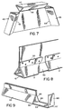
- Bracket 30 for forming the peak in a roof or similar angled construction by attaching two beams 2 and 2'. While the angle shown is relatively large, the bracket 30 can be formed to provide virtually any angle required. As described above for bracket 20, the sheet of cold formed steel is pre-cut to the desired angle, in this case forming a hexagon. A notch 33 is made at the apex 35 to allow the triangles to be formed independently of each other. The triangles 31 and 31' are formed by creating three folds parallel to the angle-cut edges 32 and 34, with the edges at the apex 35. The triangles 31 and 31' have sides slightly smaller than the inner dimensions of the triangle of a beam.
- the dimensions of the triangles 31 and 31' can be larger than the outer dimensions of the beams so that the bracket is fined over the outside of the end of the beam to be joined.
- the bracket 30 and beams 2 and 2' are attached as shown in Figure 6, with fasteners being driven through the wings of the respective beams and through single wing 36 of the bracket.
- the pieces may be welded together. Holes may be pre-drilled for the desired fasteners.
- Three beams may be joined together using a bracket of the configuration shown in Figure 7. Edges 42 and 44 of the sheet metal are cut at the desired angles, then folded inward to form triangles 43 and 45. Edge 46 is also folded inward to form triangle 47. As with bracket 30, notches are cut between the individual triangles. The ends of the beams to be joined are slid over the appropriate triangle and fastened as above. The angles may be varied as needed by pre-cutting the sheet metal.
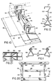
- Two beams may be attached together end-to-end by either inserting a telescoping-type connector bracket into the ends of each beam 2 and 2' or inserting the ends of the beams into the telescoping connector.
- a connection of the former type is shown in Figure 8.
- the telescoping connector bracket 62 consists of a triangular tube formed by bending a single piece of sheet steel along three longitudinal lines into dimensions that are slightly smaller than the interior dimensions of the beam triangle 10. Alternatively, the dimensions of the triangular tube can be larger than the outer dimensions of the beam triangle 10 so that the bracket is fined over the ends of the beams to be joined.
- the bracket 62 should fit closely within the triangle 10 to provide optimal support.
- Fasteners 50 or welds are then used to attach each beam 2 and 2' to the connector 62. As illustrated, the fasteners are driven through the respective wings of the connector and beams. Where the ends of the beams are inserted into the telescoping connector, the triangle of the connector has dimensions slightly larger than the outer dimensions of the beams.
- the connector or end joint illustrated in Figure 9 provides a means for directly attaching a beam to a wood stud (or other construction material) according to an aspect of the present invention.
- the triangular portion 63 can be either a beam itself, or a connector which telescopes with a beam, similar to the embodiment of Figure 8. In either case, the triangular portion 63 is formed in the same manner as the beam of Figure 2. Near the end of the beam, a section of the triangle is cut away by making a lengthwise cut along each of the lower corners 65 of the triangle, leaving only the base of the triangle. This creates an extension 64 which is generally flat (except for curvature at the edges 66 corresponding to the lower corners of the triangle).
- extension 64 For a 2 x 4 stud, the end of extension 64 is bent upward to create a space of 2 inches between the location of the cut 66 and the upwardly bent end 68. The 2 x 4 stud is then fined within the space, and fasteners such as nails or wood screws are used to attach the beam to the stud.
- the extension 64 provides additional support and stability for a composite structure made of beams and other construction material, such as, in this example, wood studs.
- the space may be adapted to fit any construction material by adjusting the location of the cut 66 and the bend 67.
- FIG 10. An alternative embodiment of the end joint of Figure 9 is illustrated in Figure 10. This embodiment differs from that of Figure 9 in that the triangular portion 72 is formed after the extensions are defined.
- a flat sheet of stainless steel is cut with two end sections 73 and 74 width L1 and a center of width L2 which equals L1 plus the outer width of the triangular portion 72 (shown unfolded by the dashed lines).
- a lengthwise cut is made in from the ends along a line that will be the first corner 75 of the triangular section 72, leaving extension 76 and 77 with width L3.
- the metal sheet is then folded lengthwise to create corner 75.
- the center portion is folded lengthwise again to form corner 78 and bent at line 79 to form a lip 80.
- End tabs 81 and 82 are folded inward, against the ends of triangular section 72 to provide additional strength and to provide means for attachment to one side of a 2 x 4 stud or other construction materials.
- tab 82 is shown with wood screws through it for attachment to stud 84 (shown in dashed lines). Stud 84 fits within a space between tab 82 and extension end 86, which is bent upward to be parallel to tab 82.
- Fasteners may be driven through the outside of end 86 into stud 84. (As in other components, holes may be pre-drilled in the metal to facilitate assembly.)
- Extension 76 is shown without an upwardly bent end. In this configuration, attachment to a wood stud (not shown) can be accomplished by driving fasteners upwardly through extension 76 and outwardly through tab 81. By not bending up the end, connection can be made to a large beam or other large dimension structure, e.g., the edge of a concrete block.
- the combination of tab 81 and extension 76 can also be bent to create a curved contact surface for attachment to pipes or other rounded surfaces.
- An end joint configured as that shown in Figure 10 retains the advantages of high strength and simple manufacture of the triangular beam while providing versatility for adaptation to other building surfaces.
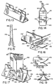
- the bracket 90 illustrated in Figure 11, is formed from a strip of sheet steel and may be of any length for use in connecting two neighboring beams.
- the metal is bent laterally to conform to the outer shape and dimensions of the beams to be joined.
- both beams 92 and 94 are oriented in the same direction, with bases 96 and 97 facing downward.
- the ends of bracket 90 are bent to conform with the sides of the beams 92 and 93 and then bent downward at the center to wrap around the wings 98 and 99 of the beams.
- Fasteners, here, machine screws 100 are driven through the bracket and wings of each beam.
- bracket 90 It is possible to join a string of beams by continuing the extension 93 of bracket 90 for whatever length is needed, bending the bracket to conform to the upper profiles of the beams for each beam to be joined. For example, if a third beam were to be attached between beams 92 and 94, three lateral bends would be made in the center of extension 90 to conform to the wings and sides of the third beam.
- Bracket 102 is used to join two beams which have their wings 104 pointed toward each other (only one beam is shown). Similar to previous brackets, bracket 102 is formed by making lateral bends in a strip of sheet steel. Each of the ends 106 and 107 of bracket 102 wrap around the side 108 and base 109 of the beam 103 with a lip 110 extending partially up side 111, so that each end 106 and 107 will cradle the beam.
- a fastener 112 here, a sheet metal screw, may be driven through the bracket 102 and wings 104 to secure their relative positions.
- the extension 105 between the two triangular sections may be whatever length is needed to span the two beams.
- FIG 13 a means of reinforcing a lengthy beam according to an aspect of the present invention is illustrated.
- forces on the ends of the beam may cause the beam to gape at the canter.
- This gaping can be alleviated by cutting a section 112 in one wing 114 and folding to over the other wing 116, thereby providing means for holding the wings together without requiring additional fasteners.
- wing 114 is longer than wing 116 to facilitate this reinforcement procedure.
- a notch can be made in wing 116 to allow section 112 to be folded over when wings 114 and 116 are the same length.
- FIG. 22 and 23 Another means for reinforcing a lengthy beam according to an aspect of the present invention is illustrated in Figures 22 and 23.
- a generally U-shaped cut 204 is made through both wings 200 and 201 of the beam to form a tongue 202.
- the tongues 202 from each wing are pressed together through both cut-outs and bent back around the outer side of the wing, as shown in Figure 23.
- the inner tongue (as illustrated, the tongue on the right wing) can be cut off and the remaining tongue bent across as shown.
- the shape of the cut-out is not limited to a U-shape, but can be any cut which creates a tongue-like protrusion in one wing which may be bent through the cut-out in the adjacent wing to hold the two wings together.
- FIG. 24 A third means for longitudinally reinforcing the beam according to an aspect of the present invention is shown in Figure 24.
- grooves 210 are formed in the sides 212 and base 214 of the triangle to provide additional strength against bending or gaping. By pressing or bending the metal surfaces. For ease of manufacture, the grooves are formed before the triangle itself is created. This way, large sheets of corrugated metal can be formed, then cut as needed to make the triangular beams.
- Bracket 118 is a strip of sheet steel which is bent laterally five times to form a generally triangular cross-section at its upper portion, including an open slot 124 into which the wings 126 of beam 122 fit.
- the two extensions 128 of bracket 122 can be as long or as short as needed to permit proper spacing between the stud 120 and beam 122.
- Screws 130, or other fastening means are used to fix the stud 120 within the bracket 118. Stud 120 need not actually be suspended from beam 122, but can merely be supported at its upper end by the beam 122 and bracket 118.
- Bracket 132 shown in Figure 15 is used for attaching construction materials (not shown) within space 134 to a beam (not shown), the top of which fits within generally triangular section 136, similar to the relationship between the beam and connector shown in Figure 14.
- Bracket 132 is formed in the same general manner as other brackets.
- Space 134 may be expanded to accept a wood stud or other materials, a fastener (not shown) may be driven through extensions 138 to affix the material to the connector 132, similar to that shown in Figure 14.
- the end joint 140 may be a separate connecting piece or may be a modified end of a full beam which allows one beam to be directly attached perpendicular to a second beam.
- End joint 14 is of the same construction as is the basic beam (as in Figure 2). Lengthwise cuts are made along the lower corners 142, 143 of the triangle and the wing portions above the triangle are removed.
- the side flaps 144, 145 are bent away from the extended base 146 at the same angle as the side of a beam.
- beam 148 shown in dotted lines, illustrates the relationship between the bent-back side flaps and the side of the beam to which the end joint 140 attaches.
- Extended base 146 supports the bottom (base) of beam 148, while the side flaps 144 and 145 contact the side 150 of the beam 148.
- Fasteners (not shown) may be driven through the base 146 and the side flaps 144 and 145 into beam 148 to firmly attach the end joint 140 perpendicular to the side of the beam 148.
- no beam is shown, but the flaps 144' and 145' and base extension 146 are ready to be attached to another beam which will then be parallel to beam 148.
- the end joint shown in Figure 17 may be formed either in a separate connector or at the end of a beam.
- the joint is shown formed at the end of beam 152 which is to be attached perpendicular to beam 154.
- a basic beam is cut with a lengthwise cut 158 into the centor of the base 156 for a distance approximately equal to the height of beam 154. Adjacent the lower part of the cut, the corners 157 are bent away from the base 156 to create a triangular opening corresponding to the cross-section of beam 154, with flaps 153 abutting sides 161 of beam 154.
- a second cut 159 is made laterally across both wings 160 and the lower corners 162 are bent outward to create a triangular opening corresponding to the cross-section of beam 154 with flaps 163 abutting sides 161 of beam 154.
- the beam 152 is fitted down over beam 154 making sure that the wings 164 are fully seated within cut 158.
- Fasteners 165 may be driven through the flaps 153 and 163 and into sides 161.
- Figures 18 and 19 illustrate an alternate joint for attaching the end of one beam to the top of another.
- This joint differs from that of Figure 17 in that the wings of the two beams do not meet. Instead, the wings of the beam to which the beam 170 is to be joined are inserted into slots 174. Slots 174 are formed by cutting lengthwise in from the beam end into sides 170 and bending the corners of the slots 174 back to create flaps 176 and 178. The flaps 176 and 178 are bent back to create a triangular opening with dimensions corresponding to the triangular cross-section of a basic beam, such as shown in Figure 2.
- fasteners may be driven through flaps 176 and 178 into the sides of the adjoining beam to provide a strong connection between the beams.
- Figures 20 and 21 show a support brace 180 which may be used to add strength to a structure which has extended lengths of beams.
- Brace 180 is a strip of metal with L-shaped ends 182 which wrap around the beams 184 and 186 and are fastened to each of the beams, generally located about half between the ends of the beams.
- Figure 20 illustrates a section of frame in which the inventive beams provide the vertically running portions (beams 184 and 186) attached to a 2 x 4 wood stud 188 at the base by the end joint 192, as in Figure 9.
- a third metal beam 190 which is attached using the end joint 194 as in Figure 17.
- the width of the base of triangle 10 of a beam is comparable to that of a two-by-four stud, so that anything that would have required support from the edge of a stud, such as wallboard, plywood or roofing material, will be similarly supported by the beam 2.
- the inventive beams may be substituted for the stud. Nails or other fasteners may be driven through any side of the triangle 3 to attach material which is to be supported. Other building materials may also be inserted between the wings 4 and 6 and into a beam. For example, a two-by-four stud can be inserted by spreading the triangle to provide a wood surface for nails. Similarly, plastics or composite building materials may also inserted into the beams. Where appropriate, different size beams can be used which are larger than or smaller than the dimensions of a typical 2 x 4.
- the combination of beams illustrated in Figure 25 is an alternative to a 2 x 4 wood stud (or other standard wood construction beam), possessing the features that will allow other construction materials to be directly attached.
- This "metal 2 x 4" is formed from two asymmetrically bent triangular beams 220 and 222 which have legs 221 and 223 extending from the apexes to form a flat surface 226 comparable to the 2 inch edges of a 2 x 4 wood stud into which fasteners may be driven to support other construction materials.
- the two beams 220 and 222 are joined together by a generally L-shaped connector 228 which is attached to the inside wing 230 of each beam by welding or some other fastening means (welds are shown but not labeled).
- fasteners may be driven through the bases 232 and 234 of the two triangles.
- this "metal 2 x 4" it may be used to replace the wood stud 84 illustrated in Figure 10.
- Leg 221 of the "metal 2 x 4" would be attached by fasteners to extension 77, and screw can be driven through end tab 82 into base 232.
- the material of which the beams and various brackets are made can be adapted to fit the demands of the construction project.
- Cold formed steel ranging from 24 gauge to 8 gauge can be used, as well as other metals such as aluminum, titanium and numerous steel alloys. For most common construction purposes, steel will likely be the material of choice.
- brackets described above permit the formation of virtually any angle required for building a structure without requiring angle cuts to be made in the ends of the beams. This is of particular importance where the training level of the construction personnel is such that angle cuts are a frequent source of errors.
- the inventive beams, brackets and assembly method can be substituted for traditional two-by-four framing studs, door and window headers, and any number of other applications for which wood framing is traditionally used.
- Actual I-beams can be formed by joining two beams together along their entire length using a long gusset, allowing the inventive system to be used as a substitute for traditional metal framing as well.
- the lightweight steel beam system is inexpensive to manufacture and is as easy to assemble and handle as traditional wood construction.
- the use of steel beams as an alternative to wood addresses an issue that has had significant impact on the construction industry, providing a high quality, environmentally safe material. Further, the steel beams are immune to many of the problems of wood construction, since insect damage and wood rot are not of concern.
Abstract
Description
- In recent years, the cost of lumber has increased dramatically as the result of limitations placed upon the harvesting of trees in order to preserve the environment. Within the few years alone, the cost of lumber has more than doubled. This cost increase has had a major impact on the cost of new residential construction, making new homes more difficult to build and sell at affordable prices. This, in turn has resulted in the decrease in new housing starts and increased unemployment within the construction industry.
- In addition to the increased expenses resulting from the high cost of lumber, there are other reasons that make it desirable to identify a viable alternative to wood for significant portions of the support structure in new construction. These reasons a related to the vulnerability of wood to insect damage and decay, and to the weight of the wood.
- Pre-fabricated roof and floor trusses, and frame segments are well known in the residential and light commercial construction industries. The trusses are most commonly formed from two-by-four studs joined together by steel gussets, while the frame segments are often nailed together. The pre-fabricated roof trusses are lifted onto and attached to the top of a structural frame so that the roofing material can be placed on it. The pre-fabricated floor trusses are attached to the foundation or the lower portion of the structural frame so that plywood and flooring can be placed on top and attached thereto. The pre-fabricated components of a structure provide substantial time savings in the construction process, which can be critical when the climate in some areas permits only limited time windows suitable for construction. In general, the time savings result in cost savings. Nonetheless, the significant increase in the cost of lumber had made even these pre-fab trusses and frames so expensive that an alternative is being sought.
- A lightweight steel beam has been developed by Navon which is described in PCT Application Publication Number WO 9117328, based upon United States Patent Application Numbers 07/518554 (filed May 3, 1990) and 07/674549 (filed March 22, 1991). This structural beam is an I-beam of four piece construction, where the two bearing portions (top and bottom) have a "C"-shape and the web and flange portion consists of two pieces of sheet steel which are welded at their centers and bent outward to form the triangular flanges. This beam is illustrated in cross-section in Figure 1, labeled "PRIOR ART". The flanges of the triangles are then welded to the insides of the "C"-shaped bearing portions to create the I-beam. Two beams are joined together by flat or angled gussets which are bolted or welded to the outer surface of the web.
- While the Navon beam provides an improvement upon conventional steel beams since it is over 50% lighter and it is relatively easy to use in erecting a structure, it is not trivial to fabricate. Each beam consists of four pieces which must be bent and welded together over the entire length of the beam, making the production process one that requires several specialized pieces of machinery and consumes time. Further, the joints between two beams may be subject to excessive lateral stresses since the gussets merely attach to the outside of the web, without providing any reinforcement of the joint by the beams themselves.
- US 3,129,493 describes a lightweight structural panel comprising at least are triangle cross-section beam or chord which may be connected to another similar beam, or to a surface, by a lattice web of tubing that is crimped so that it may be inserted between flanges of the beams.
- It is an advantage of the present invention to provide a versatile lightweight steel beam system which may be used in place of wood studs in construction.
- It is a further advantage of the present invention to provide a system for fabricating roof, floor and other types of trusses and frames in which the steel beams are easily fined together in any of a number of different configurations and angles.
- Another advantage of the present invention is to provide a versatile lightweight steel beam system as an alternative to both wood and traditional metal construction materials.
- According to the present invention there is provided a lightweight metal construction system having a plurality of beams, each beam formed from a single piece of sheet metal bent lengthwise along four parallel lines to form a triangular cross-section having a base, two sides and two wings, one wing corresponding to each side extending from an apex of the triangular cross-section and having a height less than a length of the each side, the beam having a first length, an inner beam surface and an outer beam surface, each of the outer and inner beam surfaces having five planar segments defined by the base, the two sides and the two wings; a plurality of connectors for connecting a first beam of the plurality of beams to a construction material having a second length and a plurality of exterior planar surfaces, each connector of the plurality of connectors having a connection point with the construction material; and a plurality of fastening means for fastening the plurality of connectors to the construction material at the connection point, the connection point having a connection width much less than each of the first and second length so that a space exists between the first beam and the construction material except at the connection point, the lightweight metal construction system characterised in that at least one of the plurality of connectors is an end joint formed by at least one lengthwise cut into an end of the first beam, the at least one lengthwise cut creating a joint opening adapted to allow the end of the first beam to contact at least two exterior planar surfaces of the construction material with at least one of the five planar segments of the first beam.
- The two wings are not attached together by a separate fastening means, but remain separable until the beam is joined to another beam or other type of construction material. For reinforcement of a long beam, notches may be made in the wings, allowing wing segments to be folded over. To attach one beam to another at any angle, brackets may be used which are constructed in a similar manner as the beams, with triangular cross-sectional inserts or sleeves which fit within or over the beam, depending on the relative dimensions of the bracket's triangle and the beam's triangle. In one embodiment, the brackets have a single triangle with an extended wing providing a gusset which is inserted between the two wings of one of the beams to be attached, and fastened in place by screws, bolts, or other fastening means. The triangular portion of the bracket is inserted into the end of the second beam, or slid over the end, depending on whether the dimensions of the bracket triangle are less than or greater than those of the beam triangle. In another embodiment, the brackets have a triangle formed at two or more edges, to create a single wing extending between the triangles. The triangles are inserted into or slid over the ends of the beams to be joined, then fastened. To connect two beams end-to-end, a telescoping fitting consisting of a triangle with outer dimensions that are slightly smaller than the inner dimensions of the triangle of the beam is used by inserting the telescoping connector into the end of each of the two beams to be connected and driving fasteners through the beams and the telescoping connector. Similarly, a triangle of slightly larger dimensions can be used as a connector by sliding the connector over the ends of the beams to be joined. The assembly procedure, i.e., piecing, sizing, cutting, is the same as that for a standard wood truss or frame, except that angle cuts on the ends of the beams are not required to assemble the steel truss according to the present invention. The cutting of angles at the ends of the beams is eliminated by using brackets with built-in angles. The beams and connectors can also be configured for use as wall studs for framing, door and window headers, and mobile home trusses.
- Modifications to the basic beam can be used to create a number of different brackets for interconnecting multiple beams, to attach the beams to wood studs, or to provide means for suspending other beams, studs or sheets of building materials from a support structure constructed from the lightweight metal construction system.
- The sheet steel of which the beams and brackets are formed can be selected according to weight requirements for a particular structure, with most common construction applications using material ranging from 24 gauge to 8 gauge steel. Other materials, such as other metals (e.g., aluminum or titanium) or high strength plastics, may be used according to the purpose of the structure. Wallboard or plywood can be nailed or screwed to the base of the triangle, which is comparable in width to the edge of a two-by-four. Wood, plastic or other materials may also be inserted into the beam between the wings, to facilitate attachment of other construction materials. The wings of the beam and the brackets can be pre-drilled so that the fastener need only be inserted through the appropriate holes to achieve the desired connection.
- Understanding of the present invention will be facilitated by consideration of the following detailed description of embodiments of the present invention, taken in conjunction with the accompanying drawings, in which like reference numerals refer to like parts and in which:
- Figure 1 is an end view of a lightweight steel beam of the prior art;
- Figure 2 is an end view of a lightweight steel beam;
- Figure 3 is a perspective view of a bracket;
- Figure 4 is a side view of the bracket of Figure 3 joining two beams;
- Figure 5 is a perspective view of a second bracket;
- Figure 6 is a side view of the bracket of Figure 5 joining two beams;
- Figure 7 is a perspective view of a bracket for joining three beams;
- Figure 8 is a perspective view, partially cut away, of a bracket joining two beams end-to-end.
- Figure 9 is a perspective view of beam section according to an aspect of the present invention for attachment to a wood stud;
- Figure 10 is a perspective view of an alternative extension according to an aspect of the present invention for attachment to a wood stud;
- Figure 11 is a side elevation of a bracket joining two beams side-by-side;
- Figure 12 is a side elevation of a bracket for joining two beams one over the other;
- Figure 13 is a perspective view of a beam according to an aspect of the present invention modified to provide additional support;
- Figure 14 is a side elevation of a bracket according to an aspect of the present invention for suspending a stud from a beam;
- Figure 15 is an end elevation of a bracket according to an aspect of the present invention for supporting construction material above a beam;
- Figure 16 is a perspective view of a connector according to an aspect of the present invention for joining two beams in a parallel arrangement;
- Figure 17 is a perspective view of a first joint according to an aspect of the present invention for joining one beam to another in a perpendicular arrangement;
- Figure 18 is a side elevation of a second joint according to an aspect of the present invention for joining one beam to another in a perpendicular arrangement;
- Figure 19 is an end view of the second joint of Figure 18;
- Figure 20 is a diagrammatic view of a frame section;
- Figure 21 is a cross-section taken along line 21-21 of Figure 20;
- Figure 22 is a perspective view of a length of beam with an alternative reinforcement means according to an aspect of the present invention;
- Figure 23 is a cross-section taken along line 23-23 of Figure 22;
- Figure 24 is an end view of a reinforced beam; and
- Figure 25 is an end view of an assembly for replacement of a wood stud.
-
- It should be noted that components of the inventive lightweight metal construction system are described as having tops, bottoms and sides for reference only. These designations are not intended to limit the construction system to use in such an orientation.
- As illustrated in Figure 2, the basic
lightweight steel beam 2 is triangular in shape with a pair ofwings apex 8 of thetriangle 10. Thetriangle 10 is created by bending a sheet of cold formed steel at four places:bottom corners shoulders wings triangle 10 is symmetrical around a line drawn from the apex 8 perpendicular to the base. Thebottom corners beam 2, so thewings - A first type of brackets for connecting two or more beams together are formed in a procedure similar to that used for the beams. As illustrated in Figures 3 and 5, the
brackets bracket 20, theedges single wing 25 extends between the twotriangles bracket 20 with twobeams 2 and 2' is illustrated in Figure 4.Fasteners 40 are shown as sheet metal screws, but may also be welds, rivets or bolts. The brackets may be pre-drilled with holes to facilitate assembly. - Illustrated in Figure 5 is a
bracket 30 for forming the peak in a roof or similar angled construction by attaching twobeams 2 and 2'. While the angle shown is relatively large, thebracket 30 can be formed to provide virtually any angle required. As described above forbracket 20, the sheet of cold formed steel is pre-cut to the desired angle, in this case forming a hexagon. Anotch 33 is made at the apex 35 to allow the triangles to be formed independently of each other. Thetriangles 31 and 31' are formed by creating three folds parallel to the angle-cut edges 32 and 34, with the edges at the apex 35. Thetriangles 31 and 31' have sides slightly smaller than the inner dimensions of the triangle of a beam. Alternatively, the dimensions of thetriangles 31 and 31' can be larger than the outer dimensions of the beams so that the bracket is fined over the outside of the end of the beam to be joined. Thebracket 30 andbeams 2 and 2' are attached as shown in Figure 6, with fasteners being driven through the wings of the respective beams and throughsingle wing 36 of the bracket. Alternatively, as with other connections, the pieces may be welded together. Holes may be pre-drilled for the desired fasteners. - Three beams may be joined together using a bracket of the configuration shown in Figure 7.
Edges triangles Edge 46 is also folded inward to formtriangle 47. As withbracket 30, notches are cut between the individual triangles. The ends of the beams to be joined are slid over the appropriate triangle and fastened as above. The angles may be varied as needed by pre-cutting the sheet metal. - Two beams may be attached together end-to-end by either inserting a telescoping-type connector bracket into the ends of each
beam 2 and 2' or inserting the ends of the beams into the telescoping connector. A connection of the former type is shown in Figure 8. Thetelescoping connector bracket 62 consists of a triangular tube formed by bending a single piece of sheet steel along three longitudinal lines into dimensions that are slightly smaller than the interior dimensions of thebeam triangle 10. Alternatively, the dimensions of the triangular tube can be larger than the outer dimensions of thebeam triangle 10 so that the bracket is fined over the ends of the beams to be joined. Thebracket 62 should fit closely within thetriangle 10 to provide optimal support.Fasteners 50 or welds are then used to attach eachbeam 2 and 2' to theconnector 62. As illustrated, the fasteners are driven through the respective wings of the connector and beams. Where the ends of the beams are inserted into the telescoping connector, the triangle of the connector has dimensions slightly larger than the outer dimensions of the beams. - The connector or end joint illustrated in Figure 9 provides a means for directly attaching a beam to a wood stud (or other construction material) according to an aspect of the present invention. The
triangular portion 63 can be either a beam itself, or a connector which telescopes with a beam, similar to the embodiment of Figure 8. In either case, thetriangular portion 63 is formed in the same manner as the beam of Figure 2. Near the end of the beam, a section of the triangle is cut away by making a lengthwise cut along each of thelower corners 65 of the triangle, leaving only the base of the triangle. This creates anextension 64 which is generally flat (except for curvature at theedges 66 corresponding to the lower corners of the triangle). For a 2 x 4 stud, the end ofextension 64 is bent upward to create a space of 2 inches between the location of thecut 66 and the upwardlybent end 68. The 2 x 4 stud is then fined within the space, and fasteners such as nails or wood screws are used to attach the beam to the stud. Theextension 64 provides additional support and stability for a composite structure made of beams and other construction material, such as, in this example, wood studs. The space may be adapted to fit any construction material by adjusting the location of thecut 66 and thebend 67. - An alternative embodiment of the end joint of Figure 9 is illustrated in Figure 10. This embodiment differs from that of Figure 9 in that the
triangular portion 72 is formed after the extensions are defined. A flat sheet of stainless steel is cut with two end sections 73 and 74 width L1 and a center of width L2 which equals L1 plus the outer width of the triangular portion 72 (shown unfolded by the dashed lines). - A lengthwise cut is made in from the ends along a line that will be the
first corner 75 of thetriangular section 72, leavingextension corner 75. The center portion is folded lengthwise again to formcorner 78 and bent atline 79 to form alip 80.End tabs triangular section 72 to provide additional strength and to provide means for attachment to one side of a 2 x 4 stud or other construction materials. As an example,tab 82 is shown with wood screws through it for attachment to stud 84 (shown in dashed lines).Stud 84 fits within a space betweentab 82 andextension end 86, which is bent upward to be parallel totab 82. Fasteners may be driven through the outside ofend 86 intostud 84. (As in other components, holes may be pre-drilled in the metal to facilitate assembly.)Extension 76 is shown without an upwardly bent end. In this configuration, attachment to a wood stud (not shown) can be accomplished by driving fasteners upwardly throughextension 76 and outwardly throughtab 81. By not bending up the end, connection can be made to a large beam or other large dimension structure, e.g., the edge of a concrete block. The combination oftab 81 andextension 76 can also be bent to create a curved contact surface for attachment to pipes or other rounded surfaces. An end joint configured as that shown in Figure 10 retains the advantages of high strength and simple manufacture of the triangular beam while providing versatility for adaptation to other building surfaces. - The
bracket 90, illustrated in Figure 11, is formed from a strip of sheet steel and may be of any length for use in connecting two neighboring beams. At each end ofbracket 90, the metal is bent laterally to conform to the outer shape and dimensions of the beams to be joined. Here, bothbeams bases bracket 90 are bent to conform with the sides of thebeams wings machine screws 100, are driven through the bracket and wings of each beam. It is possible to join a string of beams by continuing theextension 93 ofbracket 90 for whatever length is needed, bending the bracket to conform to the upper profiles of the beams for each beam to be joined. For example, if a third beam were to be attached betweenbeams extension 90 to conform to the wings and sides of the third beam. -
Bracket 102, illustrated in Figure 12, is used to join two beams which have their wings 104 pointed toward each other (only one beam is shown). Similar to previous brackets,bracket 102 is formed by making lateral bends in a strip of sheet steel. Each of theends bracket 102 wrap around theside 108 andbase 109 of thebeam 103 with alip 110 extending partially up side 111, so that eachend fastener 112, here, a sheet metal screw, may be driven through thebracket 102 and wings 104 to secure their relative positions. Theextension 105 between the two triangular sections may be whatever length is needed to span the two beams. - In Figure 13 a means of reinforcing a lengthy beam according to an aspect of the present invention is illustrated. When a beam is several meters long without support or some connection at its center, forces on the ends of the beam may cause the beam to gape at the canter. This gaping can be alleviated by cutting a
section 112 in onewing 114 and folding to over the other wing 116, thereby providing means for holding the wings together without requiring additional fasteners. As illustrated in Figure 13,wing 114 is longer than wing 116 to facilitate this reinforcement procedure. Alternatively, a notch can be made in wing 116 to allowsection 112 to be folded over whenwings 114 and 116 are the same length. - Another means for reinforcing a lengthy beam according to an aspect of the present invention is illustrated in Figures 22 and 23. A generally
U-shaped cut 204 is made through bothwings tongue 202. Thetongues 202 from each wing are pressed together through both cut-outs and bent back around the outer side of the wing, as shown in Figure 23. Alternatively, the inner tongue (as illustrated, the tongue on the right wing) can be cut off and the remaining tongue bent across as shown. The shape of the cut-out is not limited to a U-shape, but can be any cut which creates a tongue-like protrusion in one wing which may be bent through the cut-out in the adjacent wing to hold the two wings together. - A third means for longitudinally reinforcing the beam according to an aspect of the present invention is shown in Figure 24. Here,
grooves 210 are formed in thesides 212 andbase 214 of the triangle to provide additional strength against bending or gaping. By pressing or bending the metal surfaces. For ease of manufacture, the grooves are formed before the triangle itself is created. This way, large sheets of corrugated metal can be formed, then cut as needed to make the triangular beams. - Figure 14 illustrates a
bracket 118 according to an aspect of the present invention for suspending awood stud 120, or other type construction material, including other beams, from abeam 122.Bracket 118 is a strip of sheet steel which is bent laterally five times to form a generally triangular cross-section at its upper portion, including anopen slot 124 into which thewings 126 ofbeam 122 fit. The twoextensions 128 ofbracket 122 can be as long or as short as needed to permit proper spacing between thestud 120 andbeam 122.Screws 130, or other fastening means are used to fix thestud 120 within thebracket 118.Stud 120 need not actually be suspended frombeam 122, but can merely be supported at its upper end by thebeam 122 andbracket 118. - The
bracket 132 shown in Figure 15 is used for attaching construction materials (not shown) withinspace 134 to a beam (not shown), the top of which fits within generallytriangular section 136, similar to the relationship between the beam and connector shown in Figure 14.Bracket 132 is formed in the same general manner as other brackets.Space 134 may be expanded to accept a wood stud or other materials, a fastener (not shown) may be driven throughextensions 138 to affix the material to theconnector 132, similar to that shown in Figure 14. - The end joint 140 according to an aspect of the present invention illustrated in Figure 16 may be a separate connecting piece or may be a modified end of a full beam which allows one beam to be directly attached perpendicular to a second beam. Here, it is shown as a separate connecting piece. End joint 14 is of the same construction as is the basic beam (as in Figure 2). Lengthwise cuts are made along the
lower corners extended base 146 at the same angle as the side of a beam. Here,beam 148, shown in dotted lines, illustrates the relationship between the bent-back side flaps and the side of the beam to which the end joint 140 attaches.Extended base 146 supports the bottom (base) ofbeam 148, while the side flaps 144 and 145 contact theside 150 of thebeam 148. Fasteners (not shown) may be driven through thebase 146 and the side flaps 144 and 145 intobeam 148 to firmly attach the end joint 140 perpendicular to the side of thebeam 148. At the opposite end of the end joint 140, no beam is shown, but the flaps 144' and 145' andbase extension 146 are ready to be attached to another beam which will then be parallel tobeam 148. - The end joint shown in Figure 17 may be formed either in a separate connector or at the end of a beam. Here, the joint is shown formed at the end of
beam 152 which is to be attached perpendicular tobeam 154. To form the joint, a basic beam is cut with alengthwise cut 158 into the centor of thebase 156 for a distance approximately equal to the height ofbeam 154. Adjacent the lower part of the cut, thecorners 157 are bent away from the base 156 to create a triangular opening corresponding to the cross-section ofbeam 154, withflaps 153 abuttingsides 161 ofbeam 154. - A
second cut 159 is made laterally across bothwings 160 and thelower corners 162 are bent outward to create a triangular opening corresponding to the cross-section ofbeam 154 withflaps 163 abuttingsides 161 ofbeam 154. Thebeam 152 is fitted down overbeam 154 making sure that thewings 164 are fully seated withincut 158.Fasteners 165 may be driven through theflaps sides 161. - Figures 18 and 19 illustrate an alternate joint for attaching the end of one beam to the top of another. This joint differs from that of Figure 17 in that the wings of the two beams do not meet. Instead, the wings of the beam to which the
beam 170 is to be joined are inserted intoslots 174.Slots 174 are formed by cutting lengthwise in from the beam end intosides 170 and bending the corners of theslots 174 back to createflaps flaps beam 170 is to be attached, fasteners (not shown) may be driven throughflaps - Figures 20 and 21 show a
support brace 180 which may be used to add strength to a structure which has extended lengths of beams.Brace 180 is a strip of metal with L-shaped ends 182 which wrap around thebeams beams 184 and 186) attached to a 2 x 4wood stud 188 at the base by the end joint 192, as in Figure 9. At the tops of the beams is attached athird metal beam 190, which is attached using the end joint 194 as in Figure 17. - In the preferred embodiments, the width of the base of
triangle 10 of a beam is comparable to that of a two-by-four stud, so that anything that would have required support from the edge of a stud, such as wallboard, plywood or roofing material, will be similarly supported by thebeam 2. Similarly, where specialized connectors are described above for use with wood studs, the inventive beams may be substituted for the stud. Nails or other fasteners may be driven through any side of the triangle 3 to attach material which is to be supported. Other building materials may also be inserted between thewings - The combination of beams illustrated in Figure 25 is an alternative to a 2 x 4 wood stud (or other standard wood construction beam), possessing the features that will allow other construction materials to be directly attached. This "metal 2 x 4" is formed from two asymmetrically bent
triangular beams legs beams connector 228 which is attached to theinside wing 230 of each beam by welding or some other fastening means (welds are shown but not labeled). For attachment of construction materials to the broader side of the beam, fasteners may be driven through thebases wood stud 84 illustrated in Figure 10.Leg 221 of the "metal 2 x 4" would be attached by fasteners toextension 77, and screw can be driven throughend tab 82 intobase 232. - The material of which the beams and various brackets are made can be adapted to fit the demands of the construction project. Cold formed steel ranging from 24 gauge to 8 gauge can be used, as well as other metals such as aluminum, titanium and numerous steel alloys. For most common construction purposes, steel will likely be the material of choice.
- The brackets described above permit the formation of virtually any angle required for building a structure without requiring angle cuts to be made in the ends of the beams. This is of particular importance where the training level of the construction personnel is such that angle cuts are a frequent source of errors.
- The inventive beams, brackets and assembly method can be substituted for traditional two-by-four framing studs, door and window headers, and any number of other applications for which wood framing is traditionally used. Actual I-beams can be formed by joining two beams together along their entire length using a long gusset, allowing the inventive system to be used as a substitute for traditional metal framing as well. The lightweight steel beam system is inexpensive to manufacture and is as easy to assemble and handle as traditional wood construction. The use of steel beams as an alternative to wood addresses an issue that has had significant impact on the construction industry, providing a high quality, environmentally safe material. Further, the steel beams are immune to many of the problems of wood construction, since insect damage and wood rot are not of concern.
- It will be evident that there are additional embodiments which are not illustrated above but which are clearly within the scope of the present invention. The above description and drawings are therefore intended to be exemplary only and the scope of the invention is to be limited solely by the appended claims.
Claims (15)
- A lightweight metal construction system having a plurality of beams, each beam (2) formed from a single piece of sheet metal bent lengthwise along four parallel lines (12;14;16;18) to form a triangular cross-section (10) having a base, two sides and two wings, (4;6) one wing corresponding to each side extending from an apex (8) of the triangular cross-section (10) and having a height less than a length of the each side, the beam (2) having a first length, an inner beam surface and an outer beam surface, each of the outer and inner beam surfaces having five planar segments defined by the base, the two sides and the two wings (4;6); a plurality of connectors (63;78;118;132) for connecting a first beam (122) of the plurality of beams to a construction material (84;120) having a second length and a plurality of exterior planar surfaces, each connector (63;78;118;132) of the plurality of connectors (63;78;118;132) having a connection point (64;68;76,77,81,82,86;128;138) with the construction material; and a plurality of fastening means (130) for fastening the plurality of connectors (63;78;118;132) to the construction material (84;120) at the connection point (64;68;76;66;81;82;86;128;138), the connection point (64;68;76,77,81,82,86;128;136) having a connection width much less than each of the first and second length so that a space exists between the first beam and the construction material except at the connection point (64;68;76,77,81,82,86;128;138), the lightweight metal construction system characterized in that at least one of the plurality of connectors (63;78;118;132) is an end joint (63;78) formed by at least one lengthwise cut into an end of the first beam, the at least one lengthwise cut creating a joint opening (64;76,77) adapted to allow the end of the first beam (64;68;77,86;76,81) to contact at least two exterior planar surfaces of the construction material (84;120)with at least one of the five planar segments of the first beam.
- The lightweight metal construction system of claim 1, characterized in that the plurality of connectors (63;78;118;132) further includes a plurality of brackets (118;132) for connecting at least one of the beams (122) to a construction material (120), each bracket (118;132) comprising a strip of sheet metal having at least one lateral bend (124;136) therein to conform the strip to at least two of the planar segments of the outer beam surface and at least one extension (128;138) for abutting the at least two exterior planar surfaces of the construction material.
- The lightweight metal construction system of claim 2, characterized in that the bracket (118;132) has three lateral bends to conform the strip to the at least two exterior planar surfaces of the construction material (120).
- The lightweight metal construction system of claim 3, characterized in that the bracket (118;132) further has two elongated extensions (128;138) having a spacing therebetween to span a width of the construction material (120).
- The lightweight metal construction system of claim 1, characterized in that the plurality of connectors further includes a plurality of triangular telescoping connectors (20;30;43,43,47;62), each triangular telescoping connector (20;30;43,45,47;62) for joining two beams (2,2') of the plurality of beams end to end.
- The lightweight metal construction system of claim 5, characterized in that the triangular telescoping connector (30;43,45,47) is bent at an angle(32,34;42,44,46).
- The lightweight metal construction system of claim 1, characterized in that the construction material is a second beam (154) of the plurality of beams and the end joint (152) comprises a lengthwise cut (158) in the base (156) with the two sides (163) and the two wings (160,162) bent outward from the apex to conform to the two sides (161) of the second beam (154).
- The lightweight metal construction system of claim 1, characterized in that the construction material is a second beam (148) of the plurality of beams and the end joint (140) comprises a lengthwise cut along each corner (142,143) between the base (146) and the two sides (144,145) with the two sides (144,144',145,145') bent outward from the apex to conform to the base and one of the two sides (150) of the second beam (148).
- The lightweight metal construction system of claim 1, characterized in that the construction material is a second beam of the plurality of beams and the end joint (170) comprises a lengthwise cut (174) in each of the two sides (176,178) with the two sides (176,178) bent away from the lengthwise cut (174) to conform to the two sides and their corresponding two wings of the second beam.
- The lightweight metal construction system of claim 1, characterized in that the construction material is a wood stud and the end joint (63) comprises a lengthwise cut (63) along each corner between the base and the two sides and a lateral cut (66) across the two sides and the two wings to remove a section of each side and their corresponding two wings of the first beam (63).
- The lightweight metal construction system of claim 10, characterized in that the base (64) is bent (67) laterally at a 90° angle at a distance from the lateral cut (66) corresponding to a width of the wood stud.
- The lightweight metal construction system of claim 1, characterized in that the construction material is a metal stud having a substantially rectangular cross-section and the end joint (63) comprises a lengthwise cut (63) along each corner between the base and the two sides and a lateral cut (66) across the two sides and the two wings to remove a section of each side and their corresponding two wings of the first beam (63).
- The lightweight metal construction system of claim 1, further characterized in that a beam reinforcement means is provided, the beam reinforcement means comprising a pair of lateral cuts across one of the wings (114,116) to form a wing segment (112), wherein the wing segment (112) is bent across the other wing (116) of the beam.
- The lightweight metal construction system of claim 1, further characterized in that a beam reinforcement means is provided, the beam reinforcement means comprising a pair of generally U-shaped cuts (204) in each of the wings (200,201) to form a tongue (202) in one of the wings (200) which is pushed through the generally U-shaped cut (204) in the other wing (201) and bent across an outer surface of the other wing (201).
- The lightweight metal construction system of claim 1, further characterized in that a beam reinforcement means is provided, the beam reinforcement means comprising a plurality of lengthwise grooves (210) formed in the base (214) and the sides (212) of the beam.
Applications Claiming Priority (7)
| Application Number | Priority Date | Filing Date | Title |
|---|---|---|---|
| US4049493A | 1993-03-31 | 1993-03-31 | |
| US40494 | 1993-03-31 | ||
| US8298993A | 1993-06-25 | 1993-06-25 | |
| US82989 | 1993-06-25 | ||
| US08/190,643 US5499480A (en) | 1993-03-31 | 1994-02-02 | Lightweight metal truss and frame system |
| US190643 | 1994-02-02 | ||
| PCT/US1994/003508 WO1994023149A1 (en) | 1993-03-31 | 1994-03-30 | Lightweight metal truss and frame system |
Publications (2)
| Publication Number | Publication Date |
|---|---|
| EP0692053A1 EP0692053A1 (en) | 1996-01-17 |
| EP0692053B1 true EP0692053B1 (en) | 2000-10-04 |
Family
ID=26717108
Family Applications (1)
| Application Number | Title | Priority Date | Filing Date |
|---|---|---|---|
| EP94914749A Expired - Lifetime EP0692053B1 (en) | 1993-03-31 | 1994-03-30 | Lightweight metal truss and frame system |
Country Status (17)
| Country | Link |
|---|---|
| EP (1) | EP0692053B1 (en) |
| JP (1) | JPH08508798A (en) |
| AT (1) | ATE196787T1 (en) |
| AU (1) | AU685117B2 (en) |
| BR (1) | BR9405803A (en) |
| CA (1) | CA2159492A1 (en) |
| CZ (1) | CZ251395A3 (en) |
| DE (1) | DE69426073T2 (en) |
| DK (1) | DK0692053T3 (en) |
| ES (1) | ES2152978T3 (en) |
| GR (1) | GR3035186T3 (en) |
| HU (1) | HUT72379A (en) |
| NZ (1) | NZ265766A (en) |
| PL (1) | PL320748A1 (en) |
| PT (1) | PT692053E (en) |
| SK (1) | SK122095A3 (en) |
| WO (1) | WO1994023149A1 (en) |
Cited By (8)
| Publication number | Priority date | Publication date | Assignee | Title |
|---|---|---|---|---|
| RU2641333C1 (en) * | 2017-03-21 | 2018-01-17 | Александр Суренович Марутян | Curved closed profile |
| RU2645318C1 (en) * | 2017-06-06 | 2018-02-20 | Александр Суренович Марутян | Pentagonal formed hollow profile |
| RU2645317C1 (en) * | 2017-05-26 | 2018-02-20 | Александр Суренович Марутян | Semi-circular formed hollowed section |
| RU2651741C1 (en) * | 2017-05-15 | 2018-04-23 | Александр Суренович Марутян | Triangular hollow profile |
| RU2653209C1 (en) * | 2017-05-02 | 2018-05-07 | Александр Суренович Марутян | Flat-oval curved-closed profile |
| RU2655056C1 (en) * | 2017-07-06 | 2018-05-23 | Александр Суренович Марутян | Trapezoidal closed profile |
| RU2656297C1 (en) * | 2017-08-31 | 2018-06-04 | Александр Суренович Марутян | Wedge-shaped curce-closed profile |
| RU2686762C1 (en) * | 2018-07-23 | 2019-04-30 | Александр Суренович Марутян | Double-tee roll-welded profile |
Families Citing this family (5)
| Publication number | Priority date | Publication date | Assignee | Title |
|---|---|---|---|---|
| US5692353A (en) * | 1993-03-31 | 1997-12-02 | Bass, Deceased; Kenneth R. | Lumber-compatible lightweight metal construction system |
| CA2197299C (en) * | 1994-08-12 | 2006-05-16 | Morris Nankin | Structural beam and web |
| US5678384A (en) * | 1995-08-31 | 1997-10-21 | World Wide Homes Ltd. | Rapid assembly secure prefabricated building |
| AU2003903142A0 (en) | 2003-06-23 | 2003-07-03 | Palmer Tube Mills (Aust) Pty Ltd | An improved beam |
| JP7291539B2 (en) * | 2019-05-23 | 2023-06-15 | 日本製鉄株式会社 | wall structure |
Family Cites Families (13)
| Publication number | Priority date | Publication date | Assignee | Title |
|---|---|---|---|---|
| FR675888A (en) * | 1929-05-29 | 1930-02-15 | Method of establishing metal profiles and new industrial products resulting therefrom | |
| US2029645A (en) * | 1933-12-18 | 1936-02-04 | Stran Steel Corp | Structural element |
| US2167835A (en) * | 1937-12-29 | 1939-08-01 | Gerald G Greulich | Structural joist or nailer stud |
| US3129493A (en) * | 1961-06-20 | 1964-04-21 | Charles Davis Ltd | Methods for the manufacture of lightweight structural members |
| US3541749A (en) * | 1968-09-20 | 1970-11-24 | Arthur L Troutner | Metal truss |
| FR2063545A5 (en) * | 1969-10-17 | 1971-07-09 | Belle Daniel | |
| IT1014086B (en) * | 1974-05-02 | 1977-04-20 | Saip Spa | METAL SHEET PROFILE FOR FLOORS |
| US4069638A (en) * | 1974-06-05 | 1978-01-24 | Scanovator Ab | Structure of lightweight bars and connector means therefore |
| US4168596A (en) * | 1977-05-06 | 1979-09-25 | The Ceco Corporation | Standing seam metal roof structure and method of assembly |
| JPH051154Y2 (en) * | 1987-05-13 | 1993-01-13 | ||
| WO1989001549A1 (en) * | 1987-08-13 | 1989-02-23 | El Barador Holdings Pty. Ltd. | Methods of building construction |
| AU6383390A (en) * | 1989-10-11 | 1991-04-18 | Maxi-Span Holdings Pty. Limited | Purlin |
| DE4023902C2 (en) * | 1990-07-27 | 1995-04-27 | Mueller Franz | Mounting bracket |
-
1994
- 1994-03-30 JP JP6522352A patent/JPH08508798A/en active Pending
- 1994-03-30 DK DK94914749T patent/DK0692053T3/en active
- 1994-03-30 AT AT94914749T patent/ATE196787T1/en active
- 1994-03-30 CA CA002159492A patent/CA2159492A1/en not_active Abandoned
- 1994-03-30 ES ES94914749T patent/ES2152978T3/en not_active Expired - Lifetime
- 1994-03-30 WO PCT/US1994/003508 patent/WO1994023149A1/en not_active Application Discontinuation
- 1994-03-30 EP EP94914749A patent/EP0692053B1/en not_active Expired - Lifetime
- 1994-03-30 DE DE69426073T patent/DE69426073T2/en not_active Expired - Fee Related
- 1994-03-30 HU HU9502853A patent/HUT72379A/en active IP Right Revival
- 1994-03-30 CZ CZ952513A patent/CZ251395A3/en unknown
- 1994-03-30 SK SK1220-95A patent/SK122095A3/en unknown
- 1994-03-30 PT PT94914749T patent/PT692053E/en unknown
- 1994-03-30 BR BR9405803A patent/BR9405803A/en not_active Application Discontinuation
- 1994-03-30 AU AU66992/94A patent/AU685117B2/en not_active Ceased
- 1994-03-30 NZ NZ265766A patent/NZ265766A/en unknown
- 1994-03-30 PL PL94320748A patent/PL320748A1/en unknown
-
2001
- 2001-01-03 GR GR20010400005T patent/GR3035186T3/en unknown
Cited By (8)
| Publication number | Priority date | Publication date | Assignee | Title |
|---|---|---|---|---|
| RU2641333C1 (en) * | 2017-03-21 | 2018-01-17 | Александр Суренович Марутян | Curved closed profile |
| RU2653209C1 (en) * | 2017-05-02 | 2018-05-07 | Александр Суренович Марутян | Flat-oval curved-closed profile |
| RU2651741C1 (en) * | 2017-05-15 | 2018-04-23 | Александр Суренович Марутян | Triangular hollow profile |
| RU2645317C1 (en) * | 2017-05-26 | 2018-02-20 | Александр Суренович Марутян | Semi-circular formed hollowed section |
| RU2645318C1 (en) * | 2017-06-06 | 2018-02-20 | Александр Суренович Марутян | Pentagonal formed hollow profile |
| RU2655056C1 (en) * | 2017-07-06 | 2018-05-23 | Александр Суренович Марутян | Trapezoidal closed profile |
| RU2656297C1 (en) * | 2017-08-31 | 2018-06-04 | Александр Суренович Марутян | Wedge-shaped curce-closed profile |
| RU2686762C1 (en) * | 2018-07-23 | 2019-04-30 | Александр Суренович Марутян | Double-tee roll-welded profile |
Also Published As
| Publication number | Publication date |
|---|---|
| SK122095A3 (en) | 1997-09-10 |
| NZ265766A (en) | 1997-09-22 |
| AU685117B2 (en) | 1998-01-15 |
| BR9405803A (en) | 1995-12-12 |
| ATE196787T1 (en) | 2000-10-15 |
| CZ251395A3 (en) | 1996-05-15 |
| ES2152978T3 (en) | 2001-02-16 |
| HUT72379A (en) | 1996-04-29 |
| PT692053E (en) | 2001-01-31 |
| EP0692053A1 (en) | 1996-01-17 |
| GR3035186T3 (en) | 2001-04-30 |
| PL320748A1 (en) | 1997-10-27 |
| JPH08508798A (en) | 1996-09-17 |
| DE69426073T2 (en) | 2001-05-10 |
| WO1994023149A1 (en) | 1994-10-13 |
| HU9502853D0 (en) | 1995-11-28 |
| CA2159492A1 (en) | 1994-10-13 |
| AU6699294A (en) | 1994-10-24 |
| DK0692053T3 (en) | 2001-01-29 |
| DE69426073D1 (en) | 2000-11-09 |
Similar Documents
| Publication | Publication Date | Title |
|---|---|---|
| US5499480A (en) | Lightweight metal truss and frame system | |
| US5692353A (en) | Lumber-compatible lightweight metal construction system | |
| US5664388A (en) | Structural shear resisting member and method employed therein | |
| US6332299B1 (en) | Connector for multiple member frame systems | |
| EP0637656B1 (en) | Truss | |
| EP0692053B1 (en) | Lightweight metal truss and frame system | |
| CA2144664C (en) | Collapsible building truss | |
| US7367168B2 (en) | Skewed girder tie | |
| KR20060032961A (en) | An improved beam | |
| WO1999019577A1 (en) | Structural shape for use in frame construction | |
| CA2860342A1 (en) | Modular wall stud brace | |
| US6199341B1 (en) | Connection for a lightweight steel frame system | |
| SG176712A1 (en) | Concrete forming panel | |
| JP4352582B2 (en) | Steel truss joint structure | |
| AU693165B2 (en) | Connectors for dog-bone beams | |
| AU2004284104B2 (en) | Connector strip | |
| AU749109B2 (en) | Lintel | |
| JP3579575B2 (en) | Truss structure by bolt connection | |
| US20070056244A1 (en) | Connector strip | |
| JPH1030302A (en) | Wall framework member, wall framework system making use thereof and assembly method of the system | |
| NZ501684A (en) | A framing system for buildings comprising square-tooth framing members | |
| RU95118176A (en) | EASY METAL SYSTEMS FOR CREATING FARMS AND FRAMES | |
| MXPA06006461A (en) | Roof truss. | |
| JP2002527032A (en) | Building frame system | |
| AU3400300A (en) | Structures |
Legal Events
| Date | Code | Title | Description |
|---|---|---|---|
| PUAI | Public reference made under article 153(3) epc to a published international application that has entered the european phase |
Free format text: ORIGINAL CODE: 0009012 |
|
| 17P | Request for examination filed |
Effective date: 19951016 |
|
| AK | Designated contracting states |
Kind code of ref document: A1 Designated state(s): AT BE CH DE DK ES FR GB GR IE IT LI LU MC NL PT SE |
|
| 17Q | First examination report despatched |
Effective date: 19970505 |
|
| GRAG | Despatch of communication of intention to grant |
Free format text: ORIGINAL CODE: EPIDOS AGRA |
|
| GRAG | Despatch of communication of intention to grant |
Free format text: ORIGINAL CODE: EPIDOS AGRA |
|
| GRAH | Despatch of communication of intention to grant a patent |
Free format text: ORIGINAL CODE: EPIDOS IGRA |
|
| RAP1 | Party data changed (applicant data changed or rights of an application transferred) |
Owner name: PACIFIC STUD COMPANY, LLC. |
|
| GRAH | Despatch of communication of intention to grant a patent |
Free format text: ORIGINAL CODE: EPIDOS IGRA |
|
| GRAA | (expected) grant |
Free format text: ORIGINAL CODE: 0009210 |
|
| AK | Designated contracting states |
Kind code of ref document: B1 Designated state(s): AT BE CH DE DK ES FR GB GR IE IT LI LU MC NL PT SE |
|
| REF | Corresponds to: |
Ref document number: 196787 Country of ref document: AT Date of ref document: 20001015 Kind code of ref document: T |
|
| REG | Reference to a national code |
Ref country code: CH Ref legal event code: EP |
|
| REG | Reference to a national code |
Ref country code: IE Ref legal event code: FG4D |
|
| REF | Corresponds to: |
Ref document number: 69426073 Country of ref document: DE Date of ref document: 20001109 |
|
| ITF | It: translation for a ep patent filed |
Owner name: JACOBACCI & PERANI S.P.A. |
|
| ET | Fr: translation filed | ||
| REG | Reference to a national code |
Ref country code: DK Ref legal event code: T3 |
|
| REG | Reference to a national code |
Ref country code: PT Ref legal event code: SC4A Free format text: AVAILABILITY OF NATIONAL TRANSLATION Effective date: 20001030 Ref country code: CH Ref legal event code: NV Representative=s name: TROESCH SCHEIDEGGER WERNER AG |
|
| REG | Reference to a national code |
Ref country code: ES Ref legal event code: FG2A Ref document number: 2152978 Country of ref document: ES Kind code of ref document: T3 |
|
| PG25 | Lapsed in a contracting state [announced via postgrant information from national office to epo] |
Ref country code: LU Free format text: LAPSE BECAUSE OF NON-PAYMENT OF DUE FEES Effective date: 20010330 Ref country code: IE Free format text: LAPSE BECAUSE OF NON-PAYMENT OF DUE FEES Effective date: 20010330 Ref country code: GB Free format text: LAPSE BECAUSE OF NON-PAYMENT OF DUE FEES Effective date: 20010330 Ref country code: DK Free format text: LAPSE BECAUSE OF NON-PAYMENT OF DUE FEES Effective date: 20010330 |
|
| PG25 | Lapsed in a contracting state [announced via postgrant information from national office to epo] |
Ref country code: SE Free format text: LAPSE BECAUSE OF NON-PAYMENT OF DUE FEES Effective date: 20010331 Ref country code: GR Free format text: LAPSE BECAUSE OF NON-PAYMENT OF DUE FEES Effective date: 20010331 Ref country code: BE Free format text: LAPSE BECAUSE OF NON-PAYMENT OF DUE FEES Effective date: 20010331 |
|
| PLBE | No opposition filed within time limit |
Free format text: ORIGINAL CODE: 0009261 |
|
| STAA | Information on the status of an ep patent application or granted ep patent |
Free format text: STATUS: NO OPPOSITION FILED WITHIN TIME LIMIT |
|
| 26N | No opposition filed | ||
| BERE | Be: lapsed |
Owner name: PACIFIC STUD CY LLC. Effective date: 20010331 |
|
| PG25 | Lapsed in a contracting state [announced via postgrant information from national office to epo] |
Ref country code: NL Free format text: LAPSE BECAUSE OF NON-PAYMENT OF DUE FEES Effective date: 20011001 |
|
| PGFP | Annual fee paid to national office [announced via postgrant information from national office to epo] |
Ref country code: MC Payment date: 20011001 Year of fee payment: 8 |
|
| PGFP | Annual fee paid to national office [announced via postgrant information from national office to epo] |
Ref country code: DE Payment date: 20011031 Year of fee payment: 8 |
|
| EUG | Se: european patent has lapsed |
Ref document number: 94914749.0 |
|
| REG | Reference to a national code |
Ref country code: CH Ref legal event code: PL |
|
| REG | Reference to a national code |
Ref country code: DK Ref legal event code: EBP |
|
| GBPC | Gb: european patent ceased through non-payment of renewal fee |
Effective date: 20010330 |
|
| PGFP | Annual fee paid to national office [announced via postgrant information from national office to epo] |
Ref country code: CH Payment date: 20011123 Year of fee payment: 8 |
|
| PGFP | Annual fee paid to national office [announced via postgrant information from national office to epo] |
Ref country code: PT Payment date: 20011127 Year of fee payment: 8 |
|
| PGFP | Annual fee paid to national office [announced via postgrant information from national office to epo] |
Ref country code: ES Payment date: 20011129 Year of fee payment: 8 Ref country code: AT Payment date: 20011129 Year of fee payment: 8 |
|
| PG25 | Lapsed in a contracting state [announced via postgrant information from national office to epo] |
Ref country code: FR Free format text: LAPSE BECAUSE OF NON-PAYMENT OF DUE FEES Effective date: 20011130 |
|
| NLV4 | Nl: lapsed or anulled due to non-payment of the annual fee |
Effective date: 20011001 |
|
| PGFP | Annual fee paid to national office [announced via postgrant information from national office to epo] |
Ref country code: DK Payment date: 20011203 Year of fee payment: 8 |
|
| REG | Reference to a national code |
Ref country code: CH Ref legal event code: AEN Free format text: LE BREVET A ETE REACTIVE SELON LA DEMANDE DE POURSUITE DE LA PROCEDURE DU 22.11.2001 |
|
| REG | Reference to a national code |
Ref country code: GB Ref legal event code: 728V |
|
| REG | Reference to a national code |
Ref country code: FR Ref legal event code: ST |
|
| REG | Reference to a national code |
Ref country code: IE Ref legal event code: MM4A |
|
| PGFP | Annual fee paid to national office [announced via postgrant information from national office to epo] |
Ref country code: SE Payment date: 20020326 Year of fee payment: 8 |
|
| PG25 | Lapsed in a contracting state [announced via postgrant information from national office to epo] |
Ref country code: MC Free format text: LAPSE BECAUSE OF NON-PAYMENT OF DUE FEES Effective date: 20020330 Ref country code: AT Free format text: LAPSE BECAUSE OF NON-PAYMENT OF DUE FEES Effective date: 20020330 |
|
| PG25 | Lapsed in a contracting state [announced via postgrant information from national office to epo] |
Ref country code: LI Free format text: LAPSE BECAUSE OF NON-PAYMENT OF DUE FEES Effective date: 20020331 Ref country code: ES Free format text: LAPSE BECAUSE OF NON-PAYMENT OF DUE FEES Effective date: 20020331 Ref country code: CH Free format text: LAPSE BECAUSE OF NON-PAYMENT OF DUE FEES Effective date: 20020331 |
|
| NLXE | Nl: other communications concerning ep-patents (part 3 heading xe) |
Free format text: A REQUEST FOR RESTORATION TO THE PRIOR STATE (ART. 23 OF THE PATENTS ACT) HAS BEEN FILED ON 14.02.2002. |
|
| REG | Reference to a national code |
Ref country code: GB Ref legal event code: 7281 |
|
| PG25 | Lapsed in a contracting state [announced via postgrant information from national office to epo] |
Ref country code: PT Free format text: LAPSE BECAUSE OF NON-PAYMENT OF DUE FEES Effective date: 20020930 |
|
| NLXE | Nl: other communications concerning ep-patents (part 3 heading xe) |
Free format text: THE REQUEST FOR RESTORATION TO THE PRIOR STATE AS PROVIDED FOR IN ARTICLE 23 OF THE PATENTS ACT 1995 (SEE PUBLICATION IN HEADING XE OF THE PATENT BULLETIN OF 01.05.02/05) HAS BEEN WITHDRAWN. |
|
| PG25 | Lapsed in a contracting state [announced via postgrant information from national office to epo] |
Ref country code: DE Free format text: LAPSE BECAUSE OF NON-PAYMENT OF DUE FEES Effective date: 20021001 |
|
| REG | Reference to a national code |
Ref country code: CH Ref legal event code: PL |
|
| REG | Reference to a national code |
Ref country code: PT Ref legal event code: MM4A Free format text: LAPSE DUE TO NON-PAYMENT OF FEES Effective date: 20020930 |
|
| REG | Reference to a national code |
Ref country code: FR Ref legal event code: IC |
|
| REG | Reference to a national code |
Ref country code: ES Ref legal event code: FD2A Effective date: 20030410 |
|
| PG25 | Lapsed in a contracting state [announced via postgrant information from national office to epo] |
Ref country code: IT Free format text: LAPSE BECAUSE OF NON-PAYMENT OF DUE FEES Effective date: 20050330 |