EP0691905B1 - Connecting device in a paint toning machine - Google Patents
Connecting device in a paint toning machine Download PDFInfo
- Publication number
- EP0691905B1 EP0691905B1 EP94909946A EP94909946A EP0691905B1 EP 0691905 B1 EP0691905 B1 EP 0691905B1 EP 94909946 A EP94909946 A EP 94909946A EP 94909946 A EP94909946 A EP 94909946A EP 0691905 B1 EP0691905 B1 EP 0691905B1
- Authority
- EP
- European Patent Office
- Prior art keywords
- connector
- connecting device
- toning
- spindle
- paste
- Prior art date
- Legal status (The legal status is an assumption and is not a legal conclusion. Google has not performed a legal analysis and makes no representation as to the accuracy of the status listed.)
- Expired - Lifetime
Links
- 239000003973 paint Substances 0.000 title claims abstract description 14
- 238000007789 sealing Methods 0.000 claims description 18
- 230000007547 defect Effects 0.000 description 1
Images
Classifications
-
- B—PERFORMING OPERATIONS; TRANSPORTING
- B44—DECORATIVE ARTS
- B44D—PAINTING OR ARTISTIC DRAWING, NOT OTHERWISE PROVIDED FOR; PRESERVING PAINTINGS; SURFACE TREATMENT TO OBTAIN SPECIAL ARTISTIC SURFACE EFFECTS OR FINISHES
- B44D3/00—Accessories or implements for use in connection with painting or artistic drawing, not otherwise provided for; Methods or devices for colour determination, selection, or synthesis, e.g. use of colour tables
- B44D3/06—Implements for stirring or mixing paints
-
- B—PERFORMING OPERATIONS; TRANSPORTING
- B44—DECORATIVE ARTS
- B44D—PAINTING OR ARTISTIC DRAWING, NOT OTHERWISE PROVIDED FOR; PRESERVING PAINTINGS; SURFACE TREATMENT TO OBTAIN SPECIAL ARTISTIC SURFACE EFFECTS OR FINISHES
- B44D3/00—Accessories or implements for use in connection with painting or artistic drawing, not otherwise provided for; Methods or devices for colour determination, selection, or synthesis, e.g. use of colour tables
- B44D3/06—Implements for stirring or mixing paints
- B44D3/08—Implements for stirring or mixing paints for liquid or semi-liquid paints
-
- F—MECHANICAL ENGINEERING; LIGHTING; HEATING; WEAPONS; BLASTING
- F16—ENGINEERING ELEMENTS AND UNITS; GENERAL MEASURES FOR PRODUCING AND MAINTAINING EFFECTIVE FUNCTIONING OF MACHINES OR INSTALLATIONS; THERMAL INSULATION IN GENERAL
- F16L—PIPES; JOINTS OR FITTINGS FOR PIPES; SUPPORTS FOR PIPES, CABLES OR PROTECTIVE TUBING; MEANS FOR THERMAL INSULATION IN GENERAL
- F16L37/00—Couplings of the quick-acting type
- F16L37/28—Couplings of the quick-acting type with fluid cut-off means
- F16L37/30—Couplings of the quick-acting type with fluid cut-off means with fluid cut-off means in each of two pipe-end fittings
- F16L37/32—Couplings of the quick-acting type with fluid cut-off means with fluid cut-off means in each of two pipe-end fittings at least one of two lift valves being opened automatically when the coupling is applied
- F16L37/34—Couplings of the quick-acting type with fluid cut-off means with fluid cut-off means in each of two pipe-end fittings at least one of two lift valves being opened automatically when the coupling is applied at least one of the lift valves being of the sleeve type, i.e. a sleeve being telescoped over an inner cylindrical wall
-
- F—MECHANICAL ENGINEERING; LIGHTING; HEATING; WEAPONS; BLASTING
- F16—ENGINEERING ELEMENTS AND UNITS; GENERAL MEASURES FOR PRODUCING AND MAINTAINING EFFECTIVE FUNCTIONING OF MACHINES OR INSTALLATIONS; THERMAL INSULATION IN GENERAL
- F16L—PIPES; JOINTS OR FITTINGS FOR PIPES; SUPPORTS FOR PIPES, CABLES OR PROTECTIVE TUBING; MEANS FOR THERMAL INSULATION IN GENERAL
- F16L37/00—Couplings of the quick-acting type
- F16L37/28—Couplings of the quick-acting type with fluid cut-off means
- F16L37/38—Couplings of the quick-acting type with fluid cut-off means with fluid cut-off means in only one of two pipe-end fittings
- F16L37/44—Couplings of the quick-acting type with fluid cut-off means with fluid cut-off means in only one of two pipe-end fittings with one lift valve being actuated to initiate the flow through the coupling after the two coupling parts are locked against withdrawal
-
- Y—GENERAL TAGGING OF NEW TECHNOLOGICAL DEVELOPMENTS; GENERAL TAGGING OF CROSS-SECTIONAL TECHNOLOGIES SPANNING OVER SEVERAL SECTIONS OF THE IPC; TECHNICAL SUBJECTS COVERED BY FORMER USPC CROSS-REFERENCE ART COLLECTIONS [XRACs] AND DIGESTS
- Y10—TECHNICAL SUBJECTS COVERED BY FORMER USPC
- Y10T—TECHNICAL SUBJECTS COVERED BY FORMER US CLASSIFICATION
- Y10T137/00—Fluid handling
- Y10T137/8593—Systems
- Y10T137/87917—Flow path with serial valves and/or closures
- Y10T137/87925—Separable flow path section, valve or closure in each
- Y10T137/87941—Each valve and/or closure operated by coupling motion
- Y10T137/87949—Linear motion of flow path sections operates both
Definitions
- the present invention relates to a connecting device in a paint toning machine for connecting a paste container to a toning paste supply hose of the toning machine.
- the connecting device according to the invention is particularly well suited for use in a paint toning machine as described in U.S. Patent 5,174,474.
- This paint toning machine comprises a bag-like paste container connected through hoses and a valve element to another toning paste container in the machine. Due to this arrangement the bag-like paste container can be a replaceable refill container.
- the connecting device between the replaceable paste container and the paste container that is a fixed part of the machine is relatively complicated and difficult to use.
- a further connecting device is disclosed in document EP-A-0 470 694.
- the object of the present invention is to provide a connecting device by which a toning paste container can be easily and quickly connected to a toning paste supply hose, but it can also be quickly disconnected when required without the danger of toning paste leaking from the container to the environment or air being allowed to enter the container or the supply hose.
- a connecting device which is characterized in that it comprises a first connector to be connected to a discharge aperture of the paste container and containing a valve element, a second connector to be connected to the toning paste supply hose and containing a spindle, and a connection mount for receiving the first and the second connector, for supporting them against each other and for forcing the spindle of the second connector to open the valve element of the first connector.
- the connecting device When the paste container is of a type in which the discharge aperture comprises a sealing film to be cut when the container is opened and a collar surrounding it, said collar provides a first connector for the connecting device.
- the connecting device according to the invention is characterized in that it further comprises a second connector to be connected to the toning paste supply hose and including an opening spindle for cutting said sealing film, and a connection mount for receiving the first and the second connector, for supporting them against each other and for forcing the spindle of the second connector to cut the sealing film of the first connector.
- the second connector comprises a bellows-type compressible body for making the opening spindle push forward.
- the valve element in the first connector is opened or the sealing film cut in such a way that the body of the second connector is compressed by means of the connection mount, thereby making the opening spindle therein push forward and forcing the valve element in the first connector to move to a position which opens the flow connection or to cut the sealing film.
- the body of the second connector is spring-loaded to maintain the body in the maximum length allowed by the opening spindle.
- the opening spindle comprises a sealing surface, which presses against the countersurface in the body of the second connector while said body is in the non-compressed position, and thereby closes the flow connection through the second connector.
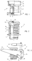
- Figure 1 shows a first connector of the connecting device according to the invention, which is intended to be connected to the discharge aperture of the paste container.
- the paste container to be used with the connecting device according to the invention is a disposable, bag-like and thus compressible paste container. It is closed with a cap and possibly also with a film under the cap.
- the first connector according to Figure 1 is screwed with its cap-like part 11 in place of the cap of the paste container.
- the first connector comprises a valve element 2, which is loaded by means of a spring 8 in a position in which it closes the flow channel running through the connector 1.
- Plate-like parts 13 and 12 on both ends of the spindle thereby function as the actual closing elements, which have countersurfaces on the body 14 around the valve element 2 and on a flange 16 attached to the bottom of the body 14.
- a discharge channel is opened for the toning paste through the connector 1.
- Cutting edges 15 have also been formed on the top surface of the valve plate 13 on the head of the valve element 2 for cutting the possible sealing film on the paste container. If there is such a sealing film on the paste container, the connection to the paste container is not opened until the valve element 2 is moved to the "open" position.
- the end of the first connector 1 which is opposite the cap-like part 11 is provided with a flange 16, on the lower surface of which a sealing ring 17 has been fitted in a ring-shaped groove near the valve plate 12.
- the sealing ring will seal the joint between the first and the second connector, as will be described later.
- FIG. 2 shows a second connector of the connecting device according to the invention in partial cross-section.
- This connector 3 comprises in its central portion a bellows-type compressible body 6 with flange-like extensions 10 and 17 at the ends thereof.
- a coil spring 7 has been fitted around the bellows-type body 6, said spring being pressed between the flange-like parts 10 and 17 and stretching the bellows 6 to the length allowed by a shaft 18 of the opening spindle 4, which shaft runs axially in the centre of the bellows.
- the flange-like part 10 is intended to lie against the flange-like part 16 of the first connector, and the flange-like part 17 is intended to be attached by means of threading to the paste supply hose of the paint toning machine.
- the end of the shaft 18 is expanded to form the opening spindle 4, which in the non-compressed position of the connector 3 supports its countersurface 9 against the countersurface provided in the flange-like part 10, thereby closing the flow channel that runs through the connector 3.
- a hex nut 19 has been fitted centrally in the opening spindle 4 at the end of the shaft 18, for fastening the opening spindle 4 to the shaft 18 and for assembling the body 6 and the flange-like parts 10 and 17 to form the second connector 3.
- FIG 3 shows a connection mount of the connecting device according to the invention, to which the first and the second connector are fitted when it is desired that the paste container is connected to the toning paste supply hose in the toning machine.
- This connection mount is supported on the body of the paint toning machine, and has a fixed position thereon. It comprises a rack part 20, on which the second connector 3 has been placed in Figure 3. This second connector is supported on the rack part 20 at its flange 17.
- the connection mount 5 further comprises a fork-like part 21, the height of which in relation to the rack part 20 can be varied by means of levers 22 and 23 in the connection mount.
- the lever 22 is triangle-shaped and is jointed at one point to the body 24 of the connection mount 5 and at another point to the lever 23.
- the lever 23 is at its other end jointed to the lower end 26 of the vertical shaft 25 which is attached to the fork-like part 21.
- the lever 22 When the lever 22 is pushed down at its third point, it forces by means of the lever 23 the vertical shaft 25 to press down and thereby also the fork-like part 21 to come down towards the rack part 20.
- the first connector 1 When the connecting device is used, the first connector 1 is brought on top of the second connector 3 in such a way that the body 14 of the first connector lies between the forks of the fork-like part 21, and the flange 16 of the lower part of the first connector remains below the fork-like part 21.
- the conic surfaces of the flange-like part 16 and the part 10 centre the first and the second connector in relation to one another, and an O-ring 17 on the lower surface of the flange 16 seals the first and the second connector in relation to one another.
- the first connector described above in Figure 1 is replaced by forming a suitable collar on the aperture of the paste container and by providing the aperture with a sealing film.
- the paste container can be connected directly to the second connector shown in Figures 2 and 3 and to the connection mount without using a first connector as shown in Figure 1.
- the second connector shown in Figure 2 must then be somewhat modified, which means in practice that the opening spindle 4 must be equipped with suitable cutting edges for cutting the closing film of the paste container and the upper surface of the flange part 10 must be equipped with a sealing surface which seals it against the collar of the discharge aperture of the paste container.
- the collar of the discharge aperture must be of the kind that it can be gripped with a fork part 21 as shown in Figure 3 to force the collar tightly against the second connector 3.
- One defect of this second embodiment compared with the first embodiment is that the paste container cannot be detached from the paint toning machine before the container is completely empty, if leaking of the paste to the environment is to be prevented. This is because the paste container is placed in the machine with its aperture downwards and is intended to be emptied gravitationally.
- connecting device according to the invention is described by way of two exemplary embodiments only, and it is to be understood that a connecting device according to the invention could be realized in a different way than in the example described without departing from the scope defined by the attached claims.
Landscapes
- Engineering & Computer Science (AREA)
- General Engineering & Computer Science (AREA)
- Mechanical Engineering (AREA)
- Coating Apparatus (AREA)
- Nozzles (AREA)
- Application Of Or Painting With Fluid Materials (AREA)
- Insulating Of Coils (AREA)
- Quick-Acting Or Multi-Walled Pipe Joints (AREA)
- Seal Device For Vehicle (AREA)
- Spray Control Apparatus (AREA)
Abstract
Description
- The present invention relates to a connecting device in a paint toning machine for connecting a paste container to a toning paste supply hose of the toning machine.
- The connecting device according to the invention is particularly well suited for use in a paint toning machine as described in U.S. Patent 5,174,474. This paint toning machine comprises a bag-like paste container connected through hoses and a valve element to another toning paste container in the machine. Due to this arrangement the bag-like paste container can be a replaceable refill container. In the paint toning machine according to U.S. Patent 5,174,474, the connecting device between the replaceable paste container and the paste container that is a fixed part of the machine is relatively complicated and difficult to use.
- A further connecting device is disclosed in document EP-A-0 470 694.
- The object of the present invention is to provide a connecting device by which a toning paste container can be easily and quickly connected to a toning paste supply hose, but it can also be quickly disconnected when required without the danger of toning paste leaking from the container to the environment or air being allowed to enter the container or the supply hose.
- The above object can be achieved by means of a connecting device according to the invention, which is characterized in that it comprises a first connector to be connected to a discharge aperture of the paste container and containing a valve element, a second connector to be connected to the toning paste supply hose and containing a spindle, and a connection mount for receiving the first and the second connector, for supporting them against each other and for forcing the spindle of the second connector to open the valve element of the first connector.
- When the paste container is of a type in which the discharge aperture comprises a sealing film to be cut when the container is opened and a collar surrounding it, said collar provides a first connector for the connecting device. In this case the connecting device according to the invention is characterized in that it further comprises a second connector to be connected to the toning paste supply hose and including an opening spindle for cutting said sealing film, and a connection mount for receiving the first and the second connector, for supporting them against each other and for forcing the spindle of the second connector to cut the sealing film of the first connector.
- Preferably the second connector comprises a bellows-type compressible body for making the opening spindle push forward. The valve element in the first connector is opened or the sealing film cut in such a way that the body of the second connector is compressed by means of the connection mount, thereby making the opening spindle therein push forward and forcing the valve element in the first connector to move to a position which opens the flow connection or to cut the sealing film.
- Preferably the body of the second connector is spring-loaded to maintain the body in the maximum length allowed by the opening spindle. Thereby it is further preferred that the opening spindle comprises a sealing surface, which presses against the countersurface in the body of the second connector while said body is in the non-compressed position, and thereby closes the flow connection through the second connector.
- In the following an embodiment of the connecting device according to the present invention will be described in more detail with reference to the accompanying drawing, in which
- Figure 1 shows a first connector of the connecting device according to the invention in partial cross-section,
- Figure 2 shows a second connector of the connecting device according to the invention also in partial cross-section and
- Figure 3 shows a connection mount of the connecting device according to the invention, having the second connector according to Figure 2 fitted thereon.
- Figure 1 shows a first connector of the connecting device according to the invention, which is intended to be connected to the discharge aperture of the paste container. Typically the paste container to be used with the connecting device according to the invention is a disposable, bag-like and thus compressible paste container. It is closed with a cap and possibly also with a film under the cap. When the cap has been removed, the first connector according to Figure 1 is screwed with its cap-
like part 11 in place of the cap of the paste container. In addition to said cap-like part 11, the first connector comprises avalve element 2, which is loaded by means of a spring 8 in a position in which it closes the flow channel running through the connector 1. Plate-like parts body 14 around thevalve element 2 and on aflange 16 attached to the bottom of thebody 14. As thevalve element 2 is moved inside thebody 14 against the force of the spring 8, a discharge channel is opened for the toning paste through the connector 1.Cutting edges 15 have also been formed on the top surface of thevalve plate 13 on the head of thevalve element 2 for cutting the possible sealing film on the paste container. If there is such a sealing film on the paste container, the connection to the paste container is not opened until thevalve element 2 is moved to the "open" position. - The end of the first connector 1 which is opposite the cap-
like part 11 is provided with aflange 16, on the lower surface of which asealing ring 17 has been fitted in a ring-shaped groove near thevalve plate 12. The sealing ring will seal the joint between the first and the second connector, as will be described later. - Figure 2 shows a second connector of the connecting device according to the invention in partial cross-section. This
connector 3 comprises in its central portion a bellows-typecompressible body 6 with flange-like extensions coil spring 7 has been fitted around the bellows-type body 6, said spring being pressed between the flange-like parts bellows 6 to the length allowed by ashaft 18 of the opening spindle 4, which shaft runs axially in the centre of the bellows. The flange-like part 10 is intended to lie against the flange-like part 16 of the first connector, and the flange-like part 17 is intended to be attached by means of threading to the paste supply hose of the paint toning machine. The end of theshaft 18 is expanded to form the opening spindle 4, which in the non-compressed position of theconnector 3 supports itscountersurface 9 against the countersurface provided in the flange-like part 10, thereby closing the flow channel that runs through theconnector 3. Ahex nut 19 has been fitted centrally in the opening spindle 4 at the end of theshaft 18, for fastening the opening spindle 4 to theshaft 18 and for assembling thebody 6 and the flange-like parts second connector 3. - Figure 3 shows a connection mount of the connecting device according to the invention, to which the first and the second connector are fitted when it is desired that the paste container is connected to the toning paste supply hose in the toning machine. This connection mount is supported on the body of the paint toning machine, and has a fixed position thereon. It comprises a
rack part 20, on which thesecond connector 3 has been placed in Figure 3. This second connector is supported on therack part 20 at itsflange 17. Theconnection mount 5 further comprises a fork-like part 21, the height of which in relation to therack part 20 can be varied by means oflevers lever 22 is triangle-shaped and is jointed at one point to thebody 24 of theconnection mount 5 and at another point to thelever 23. Thelever 23 is at its other end jointed to the lower end 26 of thevertical shaft 25 which is attached to the fork-like part 21. When thelever 22 is pushed down at its third point, it forces by means of thelever 23 thevertical shaft 25 to press down and thereby also the fork-like part 21 to come down towards therack part 20. - When the connecting device is used, the first connector 1 is brought on top of the
second connector 3 in such a way that thebody 14 of the first connector lies between the forks of the fork-like part 21, and theflange 16 of the lower part of the first connector remains below the fork-like part 21. Thus it is possible to press the first connector 1 downwards in the direction of thesecond connector 3 by means of the fork-like part 21. When this is done, the conic surfaces of the flange-like part 16 and thepart 10 centre the first and the second connector in relation to one another, and an O-ring 17 on the lower surface of theflange 16 seals the first and the second connector in relation to one another. Thereafter, as the downward movement of the fork-like part 21 continues, thebellows 6 is compressed against the force of thespring 7, thepart 10 being detached from the spindle 4 and thevalve plate 12 of thevalve element 2 pressing against the spindle 4 and further up. As the spindle 4 is detached from thepart 10, a connection is opened through the second valve element, and the spindle 4, as its height remains unchanged, opens thevalve element 2 of the connector 1, whereby also a connection through the first connector is opened. Only after these connections are opened is thevalve element 2 in such a position that it can cut the possible sealing film on the toning paste container. - If it is desired that the toning paste container is detached from the paint toning machine, the above mentioned steps are repeated in the opposite order, whereby the
lever 22 is moved upwards, causing the first connector 1 to move upwards, closing thevalve element 2 in the first connector 1, and thepart 10 in thesecond connector 3 pressing against the countersurface of the opening spindle 4, whereby also the connection through thesecond connector 3 is closed. This enables airtight sealing of the paint toning machine system and the toning paste container prior to the airtight connection between the first and the second connector achieved by means of the O-ring 17 is opened. - According to another embodiment of the invention, the first connector described above in Figure 1 is replaced by forming a suitable collar on the aperture of the paste container and by providing the aperture with a sealing film. Thereby the paste container can be connected directly to the second connector shown in Figures 2 and 3 and to the connection mount without using a first connector as shown in Figure 1. The second connector shown in Figure 2 must then be somewhat modified, which means in practice that the opening spindle 4 must be equipped with suitable cutting edges for cutting the closing film of the paste container and the upper surface of the
flange part 10 must be equipped with a sealing surface which seals it against the collar of the discharge aperture of the paste container. In addition, the collar of the discharge aperture must be of the kind that it can be gripped with afork part 21 as shown in Figure 3 to force the collar tightly against thesecond connector 3. One defect of this second embodiment compared with the first embodiment is that the paste container cannot be detached from the paint toning machine before the container is completely empty, if leaking of the paste to the environment is to be prevented. This is because the paste container is placed in the machine with its aperture downwards and is intended to be emptied gravitationally. - In the above the connecting device according to the invention is described by way of two exemplary embodiments only, and it is to be understood that a connecting device according to the invention could be realized in a different way than in the example described without departing from the scope defined by the attached claims.
Claims (6)
- A connecting device in a paint toning machine for connecting a paste container to a toning paste supply hose of the toning machine, comprisinga first connector (1) to be connected to a discharge aperture of the paste container and containing a valve element (2), characterized in that it comprisesa second connector (3) to be connected to the toning paste supply hose and containing a spindle (4), anda connection mount (5) for receiving the first and the second connector (1, 3), for supporting them against each other and for forcing the spindle (4) of the second connector (3) to open the valve element (2) of the first connector.
- A connecting device in a paint toning machine for connecting a paste container to a toning paste supply hose of the toning machine, when a discharge aperture of the paste container comprises a sealing film to be cut when the container is opened and a collar surrounding it, said collar providing a first connector for the connecting device, characterized in that the connecting device further comprisesa second connector (3) to be connected to the toning paste supply hose and including an opening spindle (4) for cutting said sealing film, anda connection mount (5) for receiving the first and the second connector (3), for supporting them against each other and for forcing the spindle (4) of the second connector (3) to cut the sealing film of the first connector.
- A connecting device according to claim 1 or 2, characterized in that the second connector (3) comprises a bellows-type compressible body (6) for making the opening spindle (4) push forward.
- A connecting device according to claim 3, characterized in that the body (6) of the second connector (3) is spring-loaded (7) to maintain the body in the maximum length allowed by the opening spindle (4).
- A connecting device according to claim 4, characterized in that the opening spindle (4) comprises a sealing surface (9) which presses against the countersurface (10) in the body of the second connector (3) while said body is in the non-compressed position and thereby closes the flow connection through the second connector (3).
- A connecting device according to claim 1, characterized in that the valve element (2) of the first connector (1) is spring-loaded (8) in its closed position.
Applications Claiming Priority (3)
| Application Number | Priority Date | Filing Date | Title |
|---|---|---|---|
| FI931282 | 1993-03-23 | ||
| FI931282A FI92029C (en) | 1993-03-23 | 1993-03-23 | Coupling device in a target color shading machine |
| PCT/FI1994/000101 WO1994021477A1 (en) | 1993-03-23 | 1994-03-18 | Connecting device in a paint toning machine |
Publications (2)
| Publication Number | Publication Date |
|---|---|
| EP0691905A1 EP0691905A1 (en) | 1996-01-17 |
| EP0691905B1 true EP0691905B1 (en) | 1997-09-17 |
Family
ID=8537608
Family Applications (1)
| Application Number | Title | Priority Date | Filing Date |
|---|---|---|---|
| EP94909946A Expired - Lifetime EP0691905B1 (en) | 1993-03-23 | 1994-03-18 | Connecting device in a paint toning machine |
Country Status (7)
| Country | Link |
|---|---|
| US (1) | US5699831A (en) |
| EP (1) | EP0691905B1 (en) |
| AT (1) | ATE158237T1 (en) |
| AU (1) | AU6259694A (en) |
| DE (1) | DE69405721T2 (en) |
| FI (1) | FI92029C (en) |
| WO (1) | WO1994021477A1 (en) |
Families Citing this family (1)
| Publication number | Priority date | Publication date | Assignee | Title |
|---|---|---|---|---|
| JP4986520B2 (en) * | 2006-07-10 | 2012-07-25 | サーパス工業株式会社 | Coupling device for fluid transfer |
Family Cites Families (3)
| Publication number | Priority date | Publication date | Assignee | Title |
|---|---|---|---|---|
| FR2216219B1 (en) * | 1973-02-02 | 1977-09-02 | Zenith Aviat | |
| US4890642A (en) * | 1988-12-16 | 1990-01-02 | The Coca-Cola Company | Disconnect for a bag valve |
| FI85563C (en) * | 1990-08-08 | 1992-05-11 | Cimcorp Oy | Color Tinting Machine |
-
1993
- 1993-03-23 FI FI931282A patent/FI92029C/en active
-
1994
- 1994-03-18 DE DE69405721T patent/DE69405721T2/en not_active Expired - Fee Related
- 1994-03-18 US US08/522,329 patent/US5699831A/en not_active Expired - Fee Related
- 1994-03-18 EP EP94909946A patent/EP0691905B1/en not_active Expired - Lifetime
- 1994-03-18 AT AT94909946T patent/ATE158237T1/en not_active IP Right Cessation
- 1994-03-18 AU AU62596/94A patent/AU6259694A/en not_active Abandoned
- 1994-03-18 WO PCT/FI1994/000101 patent/WO1994021477A1/en not_active Ceased
Also Published As
| Publication number | Publication date |
|---|---|
| FI92029C (en) | 1994-09-26 |
| DE69405721T2 (en) | 1998-04-02 |
| WO1994021477A1 (en) | 1994-09-29 |
| AU6259694A (en) | 1994-10-11 |
| EP0691905A1 (en) | 1996-01-17 |
| DE69405721D1 (en) | 1997-10-23 |
| FI931282A0 (en) | 1993-03-23 |
| ATE158237T1 (en) | 1997-10-15 |
| FI92029B (en) | 1994-06-15 |
| US5699831A (en) | 1997-12-23 |
Similar Documents
| Publication | Publication Date | Title |
|---|---|---|
| US5307964A (en) | Aerosol extension | |
| US4877065A (en) | Decanting device for liquids, e.g. permanent wave agents | |
| US4274455A (en) | Toner loading device | |
| US4189068A (en) | Perforating and sealing device for carbon dioxide capsules and suchlike | |
| JP2002522307A (en) | Sealing valve for container | |
| GB2125129A (en) | Quick-disconnect couplings | |
| KR960700174A (en) | MATERIAL HANDLING SYSTEM | |
| IE58284B1 (en) | Dispensing container for highly viscous package component and expulsion device for the container | |
| WO1998006626A3 (en) | Pressurized fluid container | |
| JPH0398803A (en) | Device for filling container | |
| GB1590267A (en) | Manually operable liquid atomizer | |
| US2400231A (en) | Means for dispensing liquids having low boiling points | |
| US5699831A (en) | Connecting device in a paint toning machine | |
| GB2025577A (en) | Valve arrangements | |
| US4211344A (en) | Sack retention and pressurizing for aerosol type dispensers | |
| EP0363444B1 (en) | Valve for tar-sprayer | |
| US2748984A (en) | Hermetically sealed spray packages and needle valves therefor | |
| GB2058264A (en) | Casks and like containers | |
| JPH0940086A (en) | A device for storing liquid or pasty products and dispensing a specified amount | |
| US6000582A (en) | Cartridge and cartridge system | |
| US4167956A (en) | Small container for liquid gas | |
| EP0197459A2 (en) | Diaphragm valve | |
| US20060060614A1 (en) | Remote aerosol dispensing system | |
| CN209018536U (en) | A kind of oil bottle | |
| JPS58160260A (en) | Dispenser for liquid, paste and powder |
Legal Events
| Date | Code | Title | Description |
|---|---|---|---|
| PUAI | Public reference made under article 153(3) epc to a published international application that has entered the european phase |
Free format text: ORIGINAL CODE: 0009012 |
|
| 17P | Request for examination filed |
Effective date: 19951006 |
|
| AK | Designated contracting states |
Kind code of ref document: A1 Designated state(s): AT BE CH DE DK ES FR GB GR IE IT LI NL PT SE |
|
| GRAG | Despatch of communication of intention to grant |
Free format text: ORIGINAL CODE: EPIDOS AGRA |
|
| 17Q | First examination report despatched |
Effective date: 19961204 |
|
| GRAH | Despatch of communication of intention to grant a patent |
Free format text: ORIGINAL CODE: EPIDOS IGRA |
|
| GRAH | Despatch of communication of intention to grant a patent |
Free format text: ORIGINAL CODE: EPIDOS IGRA |
|
| GRAA | (expected) grant |
Free format text: ORIGINAL CODE: 0009210 |
|
| AK | Designated contracting states |
Kind code of ref document: B1 Designated state(s): AT BE CH DE DK ES FR GB GR IE IT LI NL PT SE |
|
| PG25 | Lapsed in a contracting state [announced via postgrant information from national office to epo] |
Ref country code: LI Effective date: 19970917 Ref country code: GR Free format text: LAPSE BECAUSE OF FAILURE TO SUBMIT A TRANSLATION OF THE DESCRIPTION OR TO PAY THE FEE WITHIN THE PRESCRIBED TIME-LIMIT Effective date: 19970917 Ref country code: ES Free format text: THE PATENT HAS BEEN ANNULLED BY A DECISION OF A NATIONAL AUTHORITY Effective date: 19970917 Ref country code: DK Free format text: LAPSE BECAUSE OF NON-PAYMENT OF DUE FEES Effective date: 19970917 Ref country code: CH Effective date: 19970917 Ref country code: BE Effective date: 19970917 Ref country code: AT Effective date: 19970917 |
|
| REF | Corresponds to: |
Ref document number: 158237 Country of ref document: AT Date of ref document: 19971015 Kind code of ref document: T |
|
| REG | Reference to a national code |
Ref country code: CH Ref legal event code: EP |
|
| ITF | It: translation for a ep patent filed | ||
| REF | Corresponds to: |
Ref document number: 69405721 Country of ref document: DE Date of ref document: 19971023 |
|
| PG25 | Lapsed in a contracting state [announced via postgrant information from national office to epo] |
Ref country code: PT Effective date: 19971217 |
|
| ET | Fr: translation filed | ||
| REG | Reference to a national code |
Ref country code: IE Ref legal event code: FG4D Free format text: 76576 |
|
| PG25 | Lapsed in a contracting state [announced via postgrant information from national office to epo] |
Ref country code: IE Free format text: LAPSE BECAUSE OF NON-PAYMENT OF DUE FEES Effective date: 19980318 |
|
| REG | Reference to a national code |
Ref country code: CH Ref legal event code: PL |
|
| PLBE | No opposition filed within time limit |
Free format text: ORIGINAL CODE: 0009261 |
|
| STAA | Information on the status of an ep patent application or granted ep patent |
Free format text: STATUS: NO OPPOSITION FILED WITHIN TIME LIMIT |
|
| 26N | No opposition filed | ||
| PGFP | Annual fee paid to national office [announced via postgrant information from national office to epo] |
Ref country code: GB Payment date: 19990308 Year of fee payment: 6 |
|
| PGFP | Annual fee paid to national office [announced via postgrant information from national office to epo] |
Ref country code: SE Payment date: 19990318 Year of fee payment: 6 Ref country code: DE Payment date: 19990318 Year of fee payment: 6 |
|
| PGFP | Annual fee paid to national office [announced via postgrant information from national office to epo] |
Ref country code: FR Payment date: 19990319 Year of fee payment: 6 |
|
| PGFP | Annual fee paid to national office [announced via postgrant information from national office to epo] |
Ref country code: NL Payment date: 19990331 Year of fee payment: 6 |
|
| PG25 | Lapsed in a contracting state [announced via postgrant information from national office to epo] |
Ref country code: GB Free format text: LAPSE BECAUSE OF NON-PAYMENT OF DUE FEES Effective date: 20000318 |
|
| PG25 | Lapsed in a contracting state [announced via postgrant information from national office to epo] |
Ref country code: SE Free format text: LAPSE BECAUSE OF NON-PAYMENT OF DUE FEES Effective date: 20000319 |
|
| PG25 | Lapsed in a contracting state [announced via postgrant information from national office to epo] |
Ref country code: NL Free format text: LAPSE BECAUSE OF NON-PAYMENT OF DUE FEES Effective date: 20001001 |
|
| EUG | Se: european patent has lapsed |
Ref document number: 94909946.9 |
|
| GBPC | Gb: european patent ceased through non-payment of renewal fee |
Effective date: 20000318 |
|
| PG25 | Lapsed in a contracting state [announced via postgrant information from national office to epo] |
Ref country code: FR Free format text: LAPSE BECAUSE OF NON-PAYMENT OF DUE FEES Effective date: 20001130 |
|
| NLV4 | Nl: lapsed or anulled due to non-payment of the annual fee |
Effective date: 20001001 |
|
| REG | Reference to a national code |
Ref country code: FR Ref legal event code: ST |
|
| PG25 | Lapsed in a contracting state [announced via postgrant information from national office to epo] |
Ref country code: DE Free format text: LAPSE BECAUSE OF NON-PAYMENT OF DUE FEES Effective date: 20010103 |
|
| PG25 | Lapsed in a contracting state [announced via postgrant information from national office to epo] |
Ref country code: IT Free format text: LAPSE BECAUSE OF NON-PAYMENT OF DUE FEES;WARNING: LAPSES OF ITALIAN PATENTS WITH EFFECTIVE DATE BEFORE 2007 MAY HAVE OCCURRED AT ANY TIME BEFORE 2007. THE CORRECT EFFECTIVE DATE MAY BE DIFFERENT FROM THE ONE RECORDED. Effective date: 20050318 |