EP0691829B1 - Textile prostheses - Google Patents
Textile prostheses Download PDFInfo
- Publication number
- EP0691829B1 EP0691829B1 EP19940909216 EP94909216A EP0691829B1 EP 0691829 B1 EP0691829 B1 EP 0691829B1 EP 19940909216 EP19940909216 EP 19940909216 EP 94909216 A EP94909216 A EP 94909216A EP 0691829 B1 EP0691829 B1 EP 0691829B1
- Authority
- EP
- European Patent Office
- Prior art keywords
- fabric
- knitted
- yarn
- chain
- constructed
- Prior art date
- Legal status (The legal status is an assumption and is not a legal conclusion. Google has not performed a legal analysis and makes no representation as to the accuracy of the status listed.)
- Expired - Lifetime
Links
- 239000004753 textile Substances 0.000 title description 8
- 239000004744 fabric Substances 0.000 claims abstract description 83
- 238000010276 construction Methods 0.000 claims abstract description 19
- 238000000034 method Methods 0.000 claims abstract description 14
- 238000009940 knitting Methods 0.000 claims abstract description 9
- 238000004519 manufacturing process Methods 0.000 claims abstract description 6
- 230000008569 process Effects 0.000 claims description 8
- 108010010803 Gelatin Proteins 0.000 claims description 5
- 229920000159 gelatin Polymers 0.000 claims description 5
- 239000008273 gelatin Substances 0.000 claims description 5
- 235000019322 gelatine Nutrition 0.000 claims description 5
- 235000011852 gelatine desserts Nutrition 0.000 claims description 5
- 239000000463 material Substances 0.000 claims description 5
- 239000003550 marker Substances 0.000 claims description 4
- XLYOFNOQVPJJNP-UHFFFAOYSA-N water Substances O XLYOFNOQVPJJNP-UHFFFAOYSA-N 0.000 claims description 3
- 239000000203 mixture Substances 0.000 claims description 2
- 229920000728 polyester Polymers 0.000 claims description 2
- 238000013130 cardiovascular surgery Methods 0.000 abstract description 3
- 230000002792 vascular Effects 0.000 description 10
- 229920000295 expanded polytetrafluoroethylene Polymers 0.000 description 6
- 230000000694 effects Effects 0.000 description 4
- 239000004816 latex Substances 0.000 description 4
- 229920000126 latex Polymers 0.000 description 4
- 238000006243 chemical reaction Methods 0.000 description 3
- 238000010586 diagram Methods 0.000 description 3
- 239000008280 blood Substances 0.000 description 2
- 210000004369 blood Anatomy 0.000 description 2
- 238000002513 implantation Methods 0.000 description 2
- 238000005259 measurement Methods 0.000 description 2
- 238000004806 packaging method and process Methods 0.000 description 2
- 230000035699 permeability Effects 0.000 description 2
- 229920000642 polymer Polymers 0.000 description 2
- 208000005189 Embolism Diseases 0.000 description 1
- 208000009087 False Aneurysm Diseases 0.000 description 1
- 208000001435 Thromboembolism Diseases 0.000 description 1
- 206010048975 Vascular pseudoaneurysm Diseases 0.000 description 1
- 230000008901 benefit Effects 0.000 description 1
- 230000000740 bleeding effect Effects 0.000 description 1
- 210000004204 blood vessel Anatomy 0.000 description 1
- 230000008859 change Effects 0.000 description 1
- 230000000052 comparative effect Effects 0.000 description 1
- 238000002474 experimental method Methods 0.000 description 1
- 238000001125 extrusion Methods 0.000 description 1
- 230000035876 healing Effects 0.000 description 1
- 239000007943 implant Substances 0.000 description 1
- 238000005470 impregnation Methods 0.000 description 1
- 230000006872 improvement Effects 0.000 description 1
- 238000000338 in vitro Methods 0.000 description 1
- 230000036512 infertility Effects 0.000 description 1
- 230000007246 mechanism Effects 0.000 description 1
- 230000000750 progressive effect Effects 0.000 description 1
- 239000002510 pyrogen Substances 0.000 description 1
- 230000008707 rearrangement Effects 0.000 description 1
- 238000001356 surgical procedure Methods 0.000 description 1
Images


Classifications
-
- A—HUMAN NECESSITIES
- A61—MEDICAL OR VETERINARY SCIENCE; HYGIENE
- A61F—FILTERS IMPLANTABLE INTO BLOOD VESSELS; PROSTHESES; DEVICES PROVIDING PATENCY TO, OR PREVENTING COLLAPSING OF, TUBULAR STRUCTURES OF THE BODY, e.g. STENTS; ORTHOPAEDIC, NURSING OR CONTRACEPTIVE DEVICES; FOMENTATION; TREATMENT OR PROTECTION OF EYES OR EARS; BANDAGES, DRESSINGS OR ABSORBENT PADS; FIRST-AID KITS
- A61F2/00—Filters implantable into blood vessels; Prostheses, i.e. artificial substitutes or replacements for parts of the body; Appliances for connecting them with the body; Devices providing patency to, or preventing collapsing of, tubular structures of the body, e.g. stents
- A61F2/02—Prostheses implantable into the body
- A61F2/04—Hollow or tubular parts of organs, e.g. bladders, tracheae, bronchi or bile ducts
- A61F2/06—Blood vessels
-
- D—TEXTILES; PAPER
- D04—BRAIDING; LACE-MAKING; KNITTING; TRIMMINGS; NON-WOVEN FABRICS
- D04B—KNITTING
- D04B21/00—Warp knitting processes for the production of fabrics or articles not dependent on the use of particular machines; Fabrics or articles defined by such processes
- D04B21/20—Warp knitting processes for the production of fabrics or articles not dependent on the use of particular machines; Fabrics or articles defined by such processes specially adapted for knitting articles of particular configuration
- D04B21/205—Elongated tubular articles of small diameter, e.g. coverings or reinforcements for cables or hoses
-
- D—TEXTILES; PAPER
- D10—INDEXING SCHEME ASSOCIATED WITH SUBLASSES OF SECTION D, RELATING TO TEXTILES
- D10B—INDEXING SCHEME ASSOCIATED WITH SUBLASSES OF SECTION D, RELATING TO TEXTILES
- D10B2509/00—Medical; Hygiene
- D10B2509/06—Vascular grafts; stents
Definitions
- the present invention relates to surgical prostheses and, in particular, to improved tubular grafts for use in cardiovascular surgery, to the fabric from which the grafts are constructed and to methods of manufacturing the fabric and the grafts.
- tubular grafts have been used in cardiovascular surgery for the replacement and bypass of blood vessels.
- the tubular grafts used in such surgery are, in general, manufactured from woven or knitted textiles or from extruded polymers.
- Vascular grafts are discussed in detail by King et al ( Med . Prog . Technol ., 9 , 217-226 (1983)) and this article contains a description of the ideal vascular graft which would, among other characteristics, be easily handled and sutured, would have similar elasticity, flexibility and compliance to the host vessel and would be sufficiently strong and durable to last for the life expectancy of the patient.
- the graft must have both longitudinal and radial strength and, in fact, a high hoop modulus (radial strength and resistance to dilatation) is particularly important since this ensures that the graft maintains its diameter and, hence, maintains the flow characteristics considered necessary by the surgeon.
- graft dilatation has been associated with false aneurysm at the suture site and widely dilated grafts have also the potential for thromboembolism.
- Woven grafts may be either shuttle or rapier loom woven and are, in general, structurally stable, although some weaves do have a tendency to fray at the cut ends.
- textile grafts may be knitted and the currently available knitted grafts fall into two main categories.
- Weft knitted structures have yarns which lie predominantly in the transverse direction and are relatively easy to construct. However, they do have the disadvantages that they are generally unstable and, although they have a good hoop strength, they have a low hoop modulus.
- Warp knits such as the reverse locknit have yarns lying predominantly in the lengthwise direction and are more stable than weft knits, being less likely to unravel, and have good fray resistance characteristics. However, although stronger than weft knitted structures, they still have a tendency to dilate.
- a third type of construction for vascular grafts is to form them from an extruded polymer such as expanded polytetrafluoroethylene (ePTFE).
- ePTFE expanded polytetrafluoroethylene
- ePTFE grafts differ from textile ones in that they are microporous rather than macroporous. This gives a device which is blood tight at implant but limits healing by tissue ingrowth. Bleeding from suture holes is a greater problem with ePTFE devices.
- textile grafts are to be preferred to ePTFE ones although, as discussed above, they do have their own associated problems. It would be extremely advantageous to develop a new fabric for the constructions of grafts which has neither the stiffness of traditional woven materials, nor the low radial modulus of conventional knitted textiles.
- a tubular knitted fabric for a surgical graft characterised in that the fabric contains a Why chain and is knitted using a stitch which has an underlap of greater than two needle spaces in the bar nearer to the technical face.
- underlap refers to the yarn between loops. Each underlap extends across the fabric and up one stitch. The loops themselves are referred to as the "overlaps”.
- bar or “guide bar” refers to the device which determines the route of yarn sheets in the fabric.
- the term "technical face” refers to the side of the fabric on which loops are formed during the knitting process.
- the other side of the fabric is generally designated the “technical back”.
- Conventional knitted fabrics from which grafts are constructed are generally warp knitted using a stitch such as reverse locknit which is a 1 x 1 tricot on 2 x 1 tricot.
- a fabric of this construction has an underlap of two needle spaces in the bar nearer to the technical face and the fabrics of the present invention therefore have an underlap which is at least 50% longer than that of conventional fabrics.
- the fabrics of the invention are superior in several respects to the fabrics which are currently available and, in particular, they are resistant to radial deformation (ie, they have a high hoop modulus).
- the long underlap means that the fabrics of the present invention contain fewer loops per unit length of yarn than conventional fabrics and they therefore have lower potential for radial expansion.
- the yarn of the underlap lies in a plane which is more nearly perpendicular to the longitudinal axis of the tube than is possible for the shorter underlaps of conventional fabrics. This is illustrated in Figures 1 to 4 and is made possible in the present invention because the underlap is so much longer than that of conventional fabrics.
- the underlap extends across the fabric and up one stitch and, therefore, it is quite clear that the longer the underlap, the nearer it will be to being perpendicular to the longitudinal axis of the tube.
- the fact that the underlap lies almost perpendicular to the longitudinal axis of the tube gives rise to an increased hoop modulus in the fabric of the present invention because the underlaps, in effect, form a band around the circumference of the tube.
- a further advantage of the fabrics of the present invention is that they do not easily unravel and they have microstability, that is, all of the stitches are in a fixed position relative to one another.
- the fabric can be knitted on a standard knitting machine.
- a suitable construction for the fabric of the present invention is a Köper chain knitted on a tricot, the tricot having an underlap of greater than two needle spaces.
- Tricot is of course a known stitch andischen chains are also known.
- Köper chains are not known to have been used for any commercial application.
- One reason for this is that Koper chains are technically difficult to construct.
- a fabric in order to be commercially viable for most purposes, a fabric must be knitted at high speed. For example, a standard machine knits at speeds of about 2000 stitches per minute and speeds of up to 3000 stitches per minute have been achieved.
- the technicalities of the Köper chain it can only be knitted at around 200 stitches per minute and this is much too slow for most uses.
- a Köper chain knitted on a tricot is a new construction and is not known to have been used for any application. It is a difficult construction to manufacture but its very high radial modulus makes it extremely suitable for tubular grafts. Examples of constructions of this type which are suitable for use in the present invention are as follows:
- the size of the underlap in the bar nearer to the technical face is designated by the figures mentioned for the tricot part of the stitch, or when both parts are a tricot, by the second mentioned tricot structure.
- the underlap in the bar nearer to the technical face is three needle spaces whereas, for the 1 x 1 tricot on 5 x 1 tricot it is five needle spaces.
- the fabric is usually constructed using a biocompatible yarn such as a polyester.
- the yarn has a weight per unit length of from 30 to 100 decitex and more preferably from 35 to 60 decitex (one decitex is 1 g per 10 000 m). If the underlap is greater than three needle spaces, however, a finer yarn may be more suitable.
- the yarn is a multifilament yarn having, for example, a filament micron value of from 6 to 20 and preferably of from 10 to 15.
- the yarn may be either flat or texturised although, if a chain on 3 x 1 tricot stitch is used, it is preferred that the yarn is texturised. For the yarn which forms aischen chain this is less important and either type of yarn is equally preferred. In some cases, it may be advantageous to use a mix of flat and texturised yarn in the fabric construction.
- One way in which the fabric may be marked is to knit it from yarn of a single colour except for a single yarn of a second colour which could be used as the marker.
- the needles of the knitting machine should be of a gauge of at least 20/inch on each bed. However, it is preferred that the gauge is at least 28/inch and most preferably it will be 30/inch or greater on each bed.
- the fabric density may be between 80 and 350 stitches per cm 2 .
- density may be between 160 and 220 stitches per cm 2 .
- the fabric is knitted as a tube so that it can be used as a graft without the need to sew a seam.
- the fabric may be knitted on a machine in which there are at least 20 needles per inch on each bed although a preferred gauge is at least 28 or even 30 needles per inch. This ensures that the fabric is of a sufficiently fine gauge to be of use in a vascular graft.
- a tubular knitted surgical graft characterised in that it is constructed from a fabric containing a Köper chain and which is knitted using a stitch which has an underlap of greater than two needle spaces in the bar nearer to the technical face.
- the technical face of the fabric forms the outer face of the graft but this is certainly not essential for the functioning of the graft.
- the tube may be bifurcated or straight (that is non-bifurcated) and will generally, though not invariably, be of circular cross section.
- the preferred yarns and gauge are as described above in relation to the fabric.
- a method for manufacturing a vascular graft as described above comprising knitting a fabric in tubular form from a suitable yarn containing a Köper chain and using a stitch which has an underlap of greater than two needle spaces in the bar nearer to the technical face.
- the graft is knitted on a machine having at least 20 needles per inch, preferably 28/inch and more preferably 30/inch on each bed since this ensures that the fabric of the graft is of sufficiently fine gauge.
- corrugations may be formed in it and these may then be heat set in order to allow the tube to remain open rather than flat.
- the tube is impregnated with a water soluble, physiologically acceptable material such as gelatin.
- a water soluble, physiologically acceptable material such as gelatin.
- the impregnation of the graft with such a material ensures that when the graft is first implanted it is impermeable so that the blood loss from the graft will not be unacceptably great.
- the open structure of the knitted graft makes it possible for tissue to grow into it and, at the same time the gelatin, or other material, slowly dissolves.
- the tube will be washed, cute into lengths and inspected for flaws. It is also usual to carry out physical tests of the fabric strength and permeability to ensure that these are within acceptable limits.
- the grafts will, of course be packaged in sterile packaging, sterilised, desiccated and enclosed in the final outer packaging. It is also usual to test the grafts to check that they are of acceptable sterility and pyrogenicity.
- Figures 1 to 3 illustrate the types of stitch which are useful in the present invention and Figure 4 illustrates the reverse locknit construction which is often used for the construction of conventional grafts.
- Figure 1a illustrates the chain stitch used in the bar further from the technical face and figure 1b shows a 3 x 1 tricot which, in the fabrics of the present invention, is in the bar nearer to the technical face.
- the figure shows the underlaps 2 and the loops 4 and it can be seen that each underlap passes from one row to the row above or below and also crosses two loops (that is three needle spaces).
- Figure 2 illustrates an alternative construction.
- Figure 2a again illustrates a chain which is in the bar further from the technical face but in the bar nearer to the technical face a mixed 3 x 1, 4 x 1 tricot is used.
- the underlaps 6 in the mixed tricot pass from one vertical row to the adjacent one and, that some of them cross three and some four needle spaces.
- Figure 3 shows the stitch useful in the present invention. This time, there is a Köper chain in the bar further from the technical face (Figure 3a) and a 3 x 1 tricot in the bar nearer to the technical face (Figure 3b). The bar nearer to the technical face is therefore identical to that shown in Figure 1b.
- Figure 4 illustrates a reverse locknit of the type commonly used in grafts of conventional construction. This time, there is a 1 x 1 tricot in the bar further from the technical face and this is shown in Figure 4a. In the bar nearer to the technical face, a 2 x 1 tricot is used and this is illustrated in Figure 4b. From this figure it can be seen that each of the underlaps 8 crosses only one loop (two needle spaces) in passing from one vertical row to the next.
- dilatation This is a progressive increase in diameter with time and is most often seen with knitted grafts.
- the mechanism of dilatation is not clear but involves a rearrangement of the textile structure. It is difficult to model this accurately in vitro but an indication of the tendency of a graft to dilate can be gained from studying the relationship of diameter and pressure.
- the measurement of the variation of diameter with increasing pressure of various grafts was carried out on the apparatus shown in Figure 8.
- the apparatus shown in the Figure comprises a stand (not shown) on which is mounted a plug 12 from which a latex liner 14 is suspended.
- the lower end of the latex liner 14 is sealed and protruding into the sealed end is a tube 16 through which air can pass into the liner 14.
- Connected to the tube 16 is a pressure gauge 18 and a regulator 20 to regulate the flow of air through the tube 16.
- Mounted adjacent the latex liner 14 in such a way that it spans the diameter of the liner is a gauge (not shown) for measuring the diameter D of the graft.
- a graft 24 is mounted around the latex liner using a clamp 25 so that the inner surface of the graft 24 is in contact with the outer surface of the liner 14. The gauge will then span the diameter of the graft so that the diameter of the graft can be measured.
- Air is then passed through the tube 16 into the liner 14 so that the liner becomes pressurised and thus exerts a pressure on the graft 24.
- the diameter of the graft 24 is then measured at various different pressures.
- the graft length L can also be recorded and the variation in diameter with pressure measured for different lengths of graft.
- Table 1 and Figure 6 both show the effect of pressure on the diameters of four vascular grafts constructed from a fabric according to the present invention.
- Tables 2 and 3 and Figure 7 demonstrate that using the fabric of the present invention it is possible to form grafts having much greater radial strength than grafts formed from fabrics of conventional construction.
- Table 2 shows variation with pressure of the diameter and the change in diameter of a vascular graft knitted using the same yarn but in a reverse locknit construction and Table 3 shows similar results for Graft 3 above which was the weakest of the grafts of the present invention.
- Figure 7 is a plot showing a direct comparison of the data presented in Tables 2 and 3.
- the fabric of the present invention represents a considerable improvement over prior art knitted fabrics generally used for surgical grafts since it has a much higher radial modulus.
Landscapes
- Health & Medical Sciences (AREA)
- Engineering & Computer Science (AREA)
- Heart & Thoracic Surgery (AREA)
- Animal Behavior & Ethology (AREA)
- Oral & Maxillofacial Surgery (AREA)
- Transplantation (AREA)
- Pulmonology (AREA)
- Biomedical Technology (AREA)
- Gastroenterology & Hepatology (AREA)
- Vascular Medicine (AREA)
- Life Sciences & Earth Sciences (AREA)
- Cardiology (AREA)
- General Health & Medical Sciences (AREA)
- Public Health (AREA)
- Veterinary Medicine (AREA)
- Textile Engineering (AREA)
- Prostheses (AREA)
- Materials For Medical Uses (AREA)
- Knitting Of Fabric (AREA)
Abstract
Description
- The present invention relates to surgical prostheses and, in particular, to improved tubular grafts for use in cardiovascular surgery, to the fabric from which the grafts are constructed and to methods of manufacturing the fabric and the grafts.
- For many years, tubular grafts have been used in cardiovascular surgery for the replacement and bypass of blood vessels. The tubular grafts used in such surgery are, in general, manufactured from woven or knitted textiles or from extruded polymers.
- Vascular grafts are discussed in detail by King et al (Med. Prog. Technol., 9, 217-226 (1983)) and this article contains a description of the ideal vascular graft which would, among other characteristics, be easily handled and sutured, would have similar elasticity, flexibility and compliance to the host vessel and would be sufficiently strong and durable to last for the life expectancy of the patient. The graft must have both longitudinal and radial strength and, in fact, a high hoop modulus (radial strength and resistance to dilatation) is particularly important since this ensures that the graft maintains its diameter and, hence, maintains the flow characteristics considered necessary by the surgeon. In addition, graft dilatation has been associated with false aneurysm at the suture site and widely dilated grafts have also the potential for thromboembolism.
- Woven grafts may be either shuttle or rapier loom woven and are, in general, structurally stable, although some weaves do have a tendency to fray at the cut ends.
- However, a serious disadvantage of most woven grafts is that they have poor compliance, limited elongation and limited water permeability. These properties, in combination, mean that many woven grafts are difficult to handle during implantation and suturing.
- Alternatively, textile grafts may be knitted and the currently available knitted grafts fall into two main categories. Weft knitted structures have yarns which lie predominantly in the transverse direction and are relatively easy to construct. However, they do have the disadvantages that they are generally unstable and, although they have a good hoop strength, they have a low hoop modulus.
- Warp knits such as the reverse locknit have yarns lying predominantly in the lengthwise direction and are more stable than weft knits, being less likely to unravel, and have good fray resistance characteristics. However, although stronger than weft knitted structures, they still have a tendency to dilate.
- A third type of construction for vascular grafts is to form them from an extruded polymer such as expanded polytetrafluoroethylene (ePTFE).
- ePTFE grafts differ from textile ones in that they are microporous rather than macroporous. This gives a device which is blood tight at implant but limits healing by tissue ingrowth. Bleeding from suture holes is a greater problem with ePTFE devices.
- Because they are made by extrusion, it is difficult to make bifurcated devices from ePTFE. In contrast, textile bifurcates can be manufactured continuously without the need for joins.
- For several reasons, therefore, textile grafts are to be preferred to ePTFE ones although, as discussed above, they do have their own associated problems. It would be extremely advantageous to develop a new fabric for the constructions of grafts which has neither the stiffness of traditional woven materials, nor the low radial modulus of conventional knitted textiles.
- In a first aspect of the present invention, there is provided a tubular knitted fabric for a surgical graft, characterised in that the fabric contains a Körper chain and is knitted using a stitch which has an underlap of greater than two needle spaces in the bar nearer to the technical face.
- In the context of the present invention, the term "underlap" refers to the yarn between loops. Each underlap extends across the fabric and up one stitch. The loops themselves are referred to as the "overlaps".
- In the context of the present invention, the term "bar" or "guide bar" refers to the device which determines the route of yarn sheets in the fabric.
- In the context of the present invention, the term "technical face" refers to the side of the fabric on which loops are formed during the knitting process. The other side of the fabric is generally designated the "technical back".
- Conventional knitted fabrics from which grafts are constructed are generally warp knitted using a stitch such as reverse locknit which is a 1 x 1 tricot on 2 x 1 tricot. A fabric of this construction has an underlap of two needle spaces in the bar nearer to the technical face and the fabrics of the present invention therefore have an underlap which is at least 50% longer than that of conventional fabrics.
- The fabrics of the invention are superior in several respects to the fabrics which are currently available and, in particular, they are resistant to radial deformation (ie, they have a high hoop modulus).
- One reason for the greater modulus of the fabrics of the present invention is that the long underlap means that the fabrics of the present invention contain fewer loops per unit length of yarn than conventional fabrics and they therefore have lower potential for radial expansion. In addition, and more importantly, when the fabric of the present invention is formed into a tube for use in a graft, the yarn of the underlap lies in a plane which is more nearly perpendicular to the longitudinal axis of the tube than is possible for the shorter underlaps of conventional fabrics. This is illustrated in Figures 1 to 4 and is made possible in the present invention because the underlap is so much longer than that of conventional fabrics. As discussed above, the underlap extends across the fabric and up one stitch and, therefore, it is quite clear that the longer the underlap, the nearer it will be to being perpendicular to the longitudinal axis of the tube. The fact that the underlap lies almost perpendicular to the longitudinal axis of the tube gives rise to an increased hoop modulus in the fabric of the present invention because the underlaps, in effect, form a band around the circumference of the tube.
- A further advantage of the fabrics of the present invention is that they do not easily unravel and they have microstability, that is, all of the stitches are in a fixed position relative to one another. Thirdly, the fabric can be knitted on a standard knitting machine.
- A suitable construction for the fabric of the present invention is a Köper chain knitted on a tricot, the tricot having an underlap of greater than two needle spaces. Tricot is of course a known stitch and Körper chains are also known. However, Köper chains are not known to have been used for any commercial application. One reason for this is that Köper chains are technically difficult to construct. In addition, in order to be commercially viable for most purposes, a fabric must be knitted at high speed. For example, a standard machine knits at speeds of about 2000 stitches per minute and speeds of up to 3000 stitches per minute have been achieved. However, because of the technicalities of the Köper chain, it can only be knitted at around 200 stitches per minute and this is much too slow for most uses.
- Furthermore, a Köper chain knitted on a tricot is a new construction and is not known to have been used for any application. It is a difficult construction to manufacture but its very high radial modulus makes it extremely suitable for tubular grafts. Examples of constructions of this type which are suitable for use in the present invention are as follows:
- Köper chain on 3 x 1 tricot;
- Köper chain on 4 x 1 tricot;
- Köper chain on 5 x 1 tricot;
- In the constructions incorporating Köper chains, the size of the underlap in the bar nearer to the technical face is designated by the figures mentioned for the tricot part of the stitch, or when both parts are a tricot, by the second mentioned tricot structure. For example, for the chain on 3 x 1 tricot, the underlap in the bar nearer to the technical face is three needle spaces whereas, for the 1 x 1 tricot on 5 x 1 tricot it is five needle spaces.
- All of these structures mentioned above have been found to be particularly suitable for the construction of vascular grafts because they have a better stability in all directions, particularly circumferentially, both on a micro and a macro scale than the stitches such as the reverse locknit which are generally used in conventional graft fabrics. However, the structures which incorporate the Köper chain are particularly preferred.
- The fabric is usually constructed using a biocompatible yarn such as a polyester.
- When the fabric is knitted using a stitch which has an underlap of three needle spaces in the bar nearer to the technical face, it is preferable that the yarn has a weight per unit length of from 30 to 100 decitex and more preferably from 35 to 60 decitex (one decitex is 1 g per 10 000 m). If the underlap is greater than three needle spaces, however, a finer yarn may be more suitable.
- It is further preferred that the yarn is a multifilament yarn having, for example, a filament micron value of from 6 to 20 and preferably of from 10 to 15.
- The yarn may be either flat or texturised although, if a chain on 3 x 1 tricot stitch is used, it is preferred that the yarn is texturised. For the yarn which forms a Körper chain this is less important and either type of yarn is equally preferred. In some cases, it may be advantageous to use a mix of flat and texturised yarn in the fabric construction.
- In some cases, it may be useful to incorporate a marker into the fabric. One way in which the fabric may be marked is to knit it from yarn of a single colour except for a single yarn of a second colour which could be used as the marker.
- The needles of the knitting machine should be of a gauge of at least 20/inch on each bed. However, it is preferred that the gauge is at least 28/inch and most preferably it will be 30/inch or greater on each bed.
- The fabric density may be between 80 and 350 stitches per cm2. Preferably, density may be between 160 and 220 stitches per cm2.
- It is preferred that the fabric is knitted as a tube so that it can be used as a graft without the need to sew a seam.
- The fabric may be knitted on a machine in which there are at least 20 needles per inch on each bed although a preferred gauge is at least 28 or even 30 needles per inch. This ensures that the fabric is of a sufficiently fine gauge to be of use in a vascular graft.
- The other preferred features of the method and the yarn are as described above for the fabric.
- In a further aspect of the present invention, there is provided a tubular knitted surgical graft, characterised in that it is constructed from a fabric containing a Köper chain and which is knitted using a stitch which has an underlap of greater than two needle spaces in the bar nearer to the technical face.
- It is preferred that the technical face of the fabric forms the outer face of the graft but this is certainly not essential for the functioning of the graft.
- The tube may be bifurcated or straight (that is non-bifurcated) and will generally, though not invariably, be of circular cross section. The preferred yarns and gauge are as described above in relation to the fabric.
- In a further aspect of the invention, there is provided a method for manufacturing a vascular graft as described above, the method comprising knitting a fabric in tubular form from a suitable yarn containing a Köper chain and using a stitch which has an underlap of greater than two needle spaces in the bar nearer to the technical face.
- Again, it is preferred that the graft is knitted on a machine having at least 20 needles per inch, preferably 28/inch and more preferably 30/inch on each bed since this ensures that the fabric of the graft is of sufficiently fine gauge.
- Once the tube has been knitted, corrugations may be formed in it and these may then be heat set in order to allow the tube to remain open rather than flat.
- In addition, it is preferred that the tube is impregnated with a water soluble, physiologically acceptable material such as gelatin. The impregnation of the graft with such a material ensures that when the graft is first implanted it is impermeable so that the blood loss from the graft will not be unacceptably great. After implantation, the open structure of the knitted graft makes it possible for tissue to grow into it and, at the same time the gelatin, or other material, slowly dissolves.
- At various stages of the production, the tube will be washed, cute into lengths and inspected for flaws. It is also usual to carry out physical tests of the fabric strength and permeability to ensure that these are within acceptable limits. In general, the grafts will, of course be packaged in sterile packaging, sterilised, desiccated and enclosed in the final outer packaging. It is also usual to test the grafts to check that they are of acceptable sterility and pyrogenicity.
- The invention will now be further described in the following examples and with reference to the accompanying drawings in which:
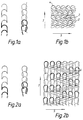
- FIGURE 1a is a diagrammatic representation of a chain;
- FIGURE 1b is a diagrammatic representation of a 3 x 1 tricot which can be superimposed on the chain of Figure 1a to give a Delaware structure;
- FIGURE 2a is a diagrammatic representation of a chain;
- FIGURE 2b is a diagrammatic representation of a mixed 3 x 1, 4 x 1 tricot which can be superimposed on the chain of Figure 2a to give a Delaware structure
Structures shown in Figs 1b,2b, however, are not within the scope of the present invention. - FIGURE 3a is a diagrammatic representation of a Köper chain;
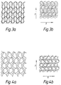
- FIGURE 3b is a diagrammatic representation of a 3 x 1 tricot which can be superimposed on the Köper chain of Figure 3a to give a structure suitable for use in the present invention;
- FIGURE 4a is a diagrammatic representation of a 1 x 1 tricot;
- FIGURE 4b is a diagrammatic representation of a 2 x 1 tricot which can be superimposed on the structure of Figure 4a to give the reverse locknit commonly used in prior art fabrics;
- FIGURE 5 is a pin diagram which gives technical information for the knitting of a fabric according to the present invention;
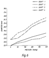
- FIGURE 6 is a plot of the variation of graft diameter with pressure for various grafts of the present invention;
- FIGURE 7 is a plot of the variation of graft diameter with pressure which compares a graft of the present invention with a graft knitted using prior art methods; and
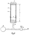
- FIGURE 8 is a diagram of the apparatus used to measure the relationship between graft diameter and pressure.
- Figures 1 to 3 illustrate the types of stitch which are useful in the present invention and Figure 4 illustrates the reverse locknit construction which is often used for the construction of conventional grafts.
- Figure 1a illustrates the chain stitch used in the bar further from the technical face and figure 1b shows a 3 x 1 tricot which, in the fabrics of the present invention, is in the bar nearer to the technical face. The figure shows the
underlaps 2 and theloops 4 and it can be seen that each underlap passes from one row to the row above or below and also crosses two loops (that is three needle spaces). - Figure 2 illustrates an alternative construction. Figure 2a again illustrates a chain which is in the bar further from the technical face but in the bar nearer to the technical face a mixed 3 x 1, 4 x 1 tricot is used. However, it can easily be seen that the
underlaps 6 in the mixed tricot pass from one vertical row to the adjacent one and, that some of them cross three and some four needle spaces. - Figure 3 shows the stitch useful in the present invention. This time, there is a Köper chain in the bar further from the technical face (Figure 3a) and a 3 x 1 tricot in the bar nearer to the technical face (Figure 3b). The bar nearer to the technical face is therefore identical to that shown in Figure 1b.
- Finally, Figure 4 illustrates a reverse locknit of the type commonly used in grafts of conventional construction. This time, there is a 1 x 1 tricot in the bar further from the technical face and this is shown in Figure 4a. In the bar nearer to the technical face, a 2 x 1 tricot is used and this is illustrated in Figure 4b. From this figure it can be seen that each of the
underlaps 8 crosses only one loop (two needle spaces) in passing from one vertical row to the next. - Clearly, therefore, the main difference between conventional constructions and those of the present invention is that in the fabrics of the present invention, the underlaps in the bar nearer to the technical face cross a greater horizontal distance each time they pass from one row to the next than is the case with the conventional fabrics (by horizontal, is meant the direction marked by
arrow 5 on Figures 1 to 4; vertical is shown by arrow 7). This means that the angle between rows of loops and the underlap is much smaller in the fabrics of the invention than in conventional fabrics and this is illustrated in the figures. If the fabric is in a tubular form with the rows of loops in the horizontal direction marked byarrow 5 passing around the circumference of the tube, then the underlaps will pass around the tube and effectively hold together the vertical columns of loops which run in a direction parallel toarrows 7. The longer the underlap and the closer it lies to the horizontal, the greater will be its effect and it is this effect which is responsible for the greatly increased radial modulus of the fabrics of the present invention. - Straight (non-bifurcated) tubular vascular grafts were knitted on a 16 bar double bed double drum raschel frame of gauge 30/inch on each bed. The yarn on
bars 8 and 9 is 1.44.27 (ie single yarn, 44 decitex, 27 filaments) T56 texturised DACRON™ and the yarn on the other bars was 2.44.27 texturised DACRON™. The details of the knitting process are shown in Figure 5 which illustrates the details of the Köper stitch which was used to construct the fabric at a density of 210 stitches per cm2. - The full details of the pattern chain, which accompany the pin diagram of Figure 5, are as follows:
Bar Body Legs 1 2-0 4-4 6-8 4-4 As body 2 2-0 6-8 10-12 6-4 As body 3 As one 2-0 6-6 6-6 6-4 4 As one 2-0 2-2 4-4 2-0 5 As one 2-2 2-4 6-8 2-2 6 2-0 6-8 6-8 2-0 As body 7 As eight 4-2 2-4 2-4 4-2 8 4-0 2-2 0-4 2-2 4-0 2-2 0-4 2-2 9 2-2 0-4 2-2 4-0 As body 10 As nine 2-0 0-2 0-2 2-0 11 2-0 0-2 0-2 2-0 As body 12 As sixteen 6-4 6-6 6-6 2-0 13 As sixteen 6-6 6-8 6-8 4-4 14 As sixteen 2-2 6-8 2-4 2-2 15 6-4 10-12 6-8 2-0 As body 16 4-4 6-8 4-4 2-0 As body - One potential problem of vascular prostheses is dilatation. This is a progressive increase in diameter with time and is most often seen with knitted grafts. The mechanism of dilatation is not clear but involves a rearrangement of the textile structure. It is difficult to model this accurately in vitro but an indication of the tendency of a graft to dilate can be gained from studying the relationship of diameter and pressure.
- The measurement of the variation of diameter with increasing pressure of various grafts was carried out on the apparatus shown in Figure 8. The apparatus shown in the Figure comprises a stand (not shown) on which is mounted a
plug 12 from which alatex liner 14 is suspended. The lower end of thelatex liner 14 is sealed and protruding into the sealed end is atube 16 through which air can pass into theliner 14. Connected to thetube 16 is apressure gauge 18 and aregulator 20 to regulate the flow of air through thetube 16. Mounted adjacent thelatex liner 14 in such a way that it spans the diameter of the liner is a gauge (not shown) for measuring the diameter D of the graft. - In order to measure the variation in diameter of a graft with increasing pressure, a
graft 24 is mounted around the latex liner using aclamp 25 so that the inner surface of thegraft 24 is in contact with the outer surface of theliner 14. The gauge will then span the diameter of the graft so that the diameter of the graft can be measured. - Air is then passed through the
tube 16 into theliner 14 so that the liner becomes pressurised and thus exerts a pressure on thegraft 24. The diameter of thegraft 24 is then measured at various different pressures. - If desired, the graft length L can also be recorded and the variation in diameter with pressure measured for different lengths of graft.
- Table 1 and Figure 6 both show the effect of pressure on the diameters of four vascular grafts constructed from a fabric according to the present invention.
-
Graft 1 was a graft knitted according to Example 1, washed at a temperature of 90°C and then sealed with gelatin. -
Graft 2 was a graft knitted according to Example 1, washed at a temperature of 40°C and then sealed with gelatin. -
Graft 3 was a graft knitted according to Example 1 then washed at a temperature of 90°C. -
Graft 4 was a graft knitted according to Example 1 then washed at a temperature of 40°C. - From Table 1 and Figure 6, it can be seen that none of the grafts used expanded greatly in diameter even at a pressure of 5.33·104 Pa (400 mm Hg).
- Tables 2 and 3 and Figure 7 demonstrate that using the fabric of the present invention it is possible to form grafts having much greater radial strength than grafts formed from fabrics of conventional construction.
- Table 2 shows variation with pressure of the diameter and the change in diameter of a vascular graft knitted using the same yarn but in a reverse locknit construction and Table 3 shows similar results for
Graft 3 above which was the weakest of the grafts of the present invention.Table 2 Pressure (mmHg) Diameter (mm) Δ Diameter (mm) 0 24 0 50 28.2 4.2 100 30 6 200 33.3 9.3 300 34.9 10.9 400 36.3 12.3 Conversion to SI-units: see Table 1 Table 3 Pressure (mmHg) Diameter (mm) Δ Diameter (mm) 0 23 0 50 24 1 100 24.5 1.5 200 25.4 2.4 300 26 3 400 26.5 3.5 Conversion to SI-units: see Table 1 - Figure 7 is a plot showing a direct comparison of the data presented in Tables 2 and 3.
- From a comparison of the Tables 2 and 3 and a study of Figure 7, it can be seen that the diameter of the graft of the present invention varied by a much smaller amount than the conventionally constructed graft. In addition, it should be borne in mind that the graft on which these comparative experiments were carried out was the one which performed the least well of the grafts of the present invention.
- It can therefore be seen that the fabric of the present invention represents a considerable improvement over prior art knitted fabrics generally used for surgical grafts since it has a much higher radial modulus.
| 1. | 2. | 3. | 4. | |||||
| Pressure mmHg | Diameter mm | Pressure mmHg | Diameter mm | Pressure mmHg | Diameter mm | Pressure | Diameter mm | |
| 0 | 22 | 0 | 22 | 0 | 23 | 0 | 23 | |
| 50 | 22.6 | 50 | 22.4 | 50 | 24 | 50 | 23.2 | |
| 100 | 23 | 100 | 22.6 | 100 | 24.5 | 100 | 24 | |
| 200 | 23.4 | 200 | 23 | 200 | 25.4 | 200 | 25 | |
| 300 | 23.7 | 300 | 23.1 | 300 | 26 | 300 | 25.6 | |
| 400 | 24 | 400 | 23.5 | 400 | 26.5 | 400 | 26 | |
| Conversion: 1 mmHg = 1 Torr = 133,3 Pa | ||||||||
Claims (20)
- A tubular knitted fabric for a surgical graft, characterised in that the fabric contains a Köper chain and is knitted using a stitch which has an underlap of greater than two needle spaces in the bar nearer to the technical face.
- A knitted fabric as claimed in claim 1 which has one of the following constructions:Köper chain on 3 x 1 tricot;Köper chain on 4 x 1 tricot;Köper chain on 5 x 1 tricot;
- A knitted fabric as claimed in claim 1 or claim 2 which is constructed from a polyester yarn.
- A knitted fabric as claimed in any one of claims 1 to 3 which is constructed from yarns having a weight per unit length of from 30 to 100 decitex.
- A knitted fabric as claimed in claim 4, wherein the yarn has a weight per unit length of from 35 to 60 decitex.
- A knitted fabric as claimed in any one of claims 1 to 5, constructed from a multifilament yarn.
- A knitted fabric as claimed in claim 6, wherein the yarn has a filament micron value of from 6 to 20.
- A knitted fabric as claimed in any one of claims 1 to 7 constructed from a flat yarn.
- A knitted fabric as claimed in any one of claims 1 to 8 constructed from a texturised yarn.
- A knitted fabric as claimed in any one of claims 1 to 7 constructed from a mix of texturised and flat yarn.
- A knitted fabric as claimed in any one of claims 1 to 10 comprising a marker.
- A knitted fabric as claimed in claim 11 wherein the marker comprises a yarn of a different colour from the rest of the fabric.
- A process for the production of a fabric as claimed in any one of claims 1 to 12, the process comprising knitting a fabric in tubular form from a suitable yarn, containing a Köper chain and using a stitch having an underlap of greater than two needle spaces in the bar nearer to the technical face.
- A process as claimed in claim 13, in which the fabric is knitted as a straight (non-bifurcated) or a bifurcated tube.
- A process as claimed in claim 13 or claim 14 wherein the fabric is knitted on a machine having at least 20 needles per inch.
- A process as claimed in any one of claims 13 to 15, further comprising the step of forming corrugations in the tube.
- A process as claimed in any one of claims 13 to 16, further comprising impregnating the tube with a water soluble physiologically acceptable material such as gelatin.
- A tubular knitted surgical graft characterised in that it is constructed from a fabric containing a Köper chain and which is knitted using a stitch which has an underlap of greater than two needle spaces in the bar nearer to the technical face.
- A knitted surgical graft constructed from a fabric as claimed in any one of claims 2 to 12.
- A knitted surgical graft as claimed in claim 18 or claim 19 which is a bifurcated tube.
Applications Claiming Priority (3)
| Application Number | Priority Date | Filing Date | Title |
|---|---|---|---|
| GB9306812 | 1993-04-01 | ||
| GB9306812A GB9306812D0 (en) | 1993-04-01 | 1993-04-01 | Textile prostheses |
| PCT/GB1994/000511 WO1994022394A1 (en) | 1993-04-01 | 1994-03-15 | Textile prostheses |
Publications (2)
| Publication Number | Publication Date |
|---|---|
| EP0691829A1 EP0691829A1 (en) | 1996-01-17 |
| EP0691829B1 true EP0691829B1 (en) | 1997-05-14 |
Family
ID=10733153
Family Applications (1)
| Application Number | Title | Priority Date | Filing Date |
|---|---|---|---|
| EP19940909216 Expired - Lifetime EP0691829B1 (en) | 1993-04-01 | 1994-03-15 | Textile prostheses |
Country Status (8)
| Country | Link |
|---|---|
| US (1) | US5732572A (en) |
| EP (1) | EP0691829B1 (en) |
| JP (1) | JP2955020B2 (en) |
| CA (1) | CA2159612C (en) |
| DE (1) | DE69403203T2 (en) |
| ES (1) | ES2102213T3 (en) |
| GB (1) | GB9306812D0 (en) |
| WO (1) | WO1994022394A1 (en) |
Families Citing this family (54)
| Publication number | Priority date | Publication date | Assignee | Title |
|---|---|---|---|---|
| US6331188B1 (en) | 1994-08-31 | 2001-12-18 | Gore Enterprise Holdings, Inc. | Exterior supported self-expanding stent-graft |
| US6015429A (en) | 1994-09-08 | 2000-01-18 | Gore Enterprise Holdings, Inc. | Procedures for introducing stents and stent-grafts |
| US5666159A (en) | 1995-04-24 | 1997-09-09 | Eastman Kodak Company | Electronic camera system with programmable transmission capability |
| US6042605A (en) | 1995-12-14 | 2000-03-28 | Gore Enterprose Holdings, Inc. | Kink resistant stent-graft |
| EP0950385A3 (en) | 1995-12-14 | 1999-10-27 | Prograft Medical, Inc. | Stent-graft deployment apparatus and method |
| US6551350B1 (en) * | 1996-12-23 | 2003-04-22 | Gore Enterprise Holdings, Inc. | Kink resistant bifurcated prosthesis |
| US6352561B1 (en) | 1996-12-23 | 2002-03-05 | W. L. Gore & Associates | Implant deployment apparatus |
| FR2791071B1 (en) * | 1999-03-16 | 2001-04-27 | Sofradim Production | ARTERIAL WALL SUBSTITUTE KNIT |
| US6547820B1 (en) * | 2000-10-03 | 2003-04-15 | Scimed Life Systems, Inc. | High profile fabric graft for arteriovenous access |
| US20020168488A1 (en) * | 2001-04-16 | 2002-11-14 | Gladfelter Harry F. | Knitted multi-property protective sleeve |
| US6554855B1 (en) * | 2001-07-03 | 2003-04-29 | Scimed Life Systems, Inc. | Low profile, high stretch, low dilation knit prosthetic device |
| US6939372B2 (en) * | 2001-07-03 | 2005-09-06 | Scimed Life Systems, Inc. | Low profile, high stretch, low dilation knit prosthetic device |
| US6540773B2 (en) * | 2001-07-03 | 2003-04-01 | Scimed Life Systems, Inc. | Low profile, high stretch knit prosthetic device |
| US7063721B2 (en) * | 2002-03-20 | 2006-06-20 | Terumo Kabushiki Kaisha | Woven tubing for stent type blood vascular prosthesis and stent type blood vascular prosthesis using the tubing |
| FR2846549B1 (en) * | 2002-11-04 | 2005-08-05 | Sofradim Production | PROSTHESIS OF REINFORCING TISSUE STRUCTURES |
| US7452374B2 (en) * | 2003-04-24 | 2008-11-18 | Maquet Cardiovascular, Llc | AV grafts with rapid post-operative self-sealing capabilities |
| FR2859624B1 (en) * | 2003-09-16 | 2005-12-02 | Sofradim Production | PROTHETIC KNIT WITH VARIABLE PROPERTIES |
| US7364587B2 (en) * | 2004-09-10 | 2008-04-29 | Scimed Life Systems, Inc. | High stretch, low dilation knit prosthetic device and method for making the same |
| US7318838B2 (en) * | 2004-12-31 | 2008-01-15 | Boston Scientific Scimed, Inc. | Smart textile vascular graft |
| US7290410B2 (en) * | 2005-04-22 | 2007-11-06 | Sofradim Production | Disassemble covering |
| US7614258B2 (en) * | 2006-10-19 | 2009-11-10 | C.R. Bard, Inc. | Prosthetic repair fabric |
| US8388679B2 (en) | 2007-01-19 | 2013-03-05 | Maquet Cardiovascular Llc | Single continuous piece prosthetic tubular aortic conduit and method for manufacturing the same |
| ES2551516T3 (en) * | 2007-06-20 | 2015-11-19 | Atex Technologies, Inc. | Compressed tissue with recovery power, devices, and methods |
| US20090004455A1 (en) * | 2007-06-27 | 2009-01-01 | Philippe Gravagna | Reinforced composite implant |
| US9308068B2 (en) * | 2007-12-03 | 2016-04-12 | Sofradim Production | Implant for parastomal hernia |
| US9242026B2 (en) * | 2008-06-27 | 2016-01-26 | Sofradim Production | Biosynthetic implant for soft tissue repair |
| FR2949688B1 (en) | 2009-09-04 | 2012-08-24 | Sofradim Production | FABRIC WITH PICOTS COATED WITH A BIORESORBABLE MICROPOROUS LAYER |
| US8696741B2 (en) | 2010-12-23 | 2014-04-15 | Maquet Cardiovascular Llc | Woven prosthesis and method for manufacturing the same |
| FR2972626B1 (en) | 2011-03-16 | 2014-04-11 | Sofradim Production | PROSTHETIC COMPRISING A THREE-DIMENSIONAL KNIT AND ADJUSTED |
| FR2977789B1 (en) | 2011-07-13 | 2013-07-19 | Sofradim Production | PROSTHETIC FOR UMBILIC HERNIA |
| FR2977790B1 (en) | 2011-07-13 | 2013-07-19 | Sofradim Production | PROSTHETIC FOR UMBILIC HERNIA |
| CN103781499B (en) | 2011-09-30 | 2016-09-28 | 索弗拉狄姆产品公司 | The reversible hardening of lightweight net |
| FR2984370B1 (en) * | 2011-12-20 | 2015-01-02 | Cousin Biotech | IMPLANTABLE AND IMPLANT KNIT FOR THE TREATMENT OF PELVIC STATIC PROLAPSUS COMPRISING SUCH A KNIT |
| FR2985271B1 (en) | 2011-12-29 | 2014-01-24 | Sofradim Production | KNITTED PICOTS |
| FR2985170B1 (en) | 2011-12-29 | 2014-01-24 | Sofradim Production | PROSTHESIS FOR INGUINAL HERNIA |
| FR2994185B1 (en) | 2012-08-02 | 2015-07-31 | Sofradim Production | PROCESS FOR THE PREPARATION OF A POROUS CHITOSAN LAYER |
| FR2995779B1 (en) | 2012-09-25 | 2015-09-25 | Sofradim Production | PROSTHETIC COMPRISING A TREILLIS AND A MEANS OF CONSOLIDATION |
| FR2995778B1 (en) | 2012-09-25 | 2015-06-26 | Sofradim Production | ABDOMINAL WALL REINFORCING PROSTHESIS AND METHOD FOR MANUFACTURING THE SAME |
| FR2995788B1 (en) | 2012-09-25 | 2014-09-26 | Sofradim Production | HEMOSTATIC PATCH AND PREPARATION METHOD |
| WO2014049446A2 (en) | 2012-09-28 | 2014-04-03 | Sofradim Production | Packaging for a hernia repair device |
| FR3006578B1 (en) | 2013-06-07 | 2015-05-29 | Sofradim Production | PROSTHESIS BASED ON TEXTILE FOR LAPAROSCOPIC PATHWAY |
| FR3006581B1 (en) | 2013-06-07 | 2016-07-22 | Sofradim Production | PROSTHESIS BASED ON TEXTILE FOR LAPAROSCOPIC PATHWAY |
| KR102088293B1 (en) * | 2013-12-16 | 2020-03-13 | 에자이 알앤드디 매니지먼트 가부시키가이샤 | Revascularization graft material |
| EP3000433B1 (en) | 2014-09-29 | 2022-09-21 | Sofradim Production | Device for introducing a prosthesis for hernia treatment into an incision and flexible textile based prosthesis |
| EP3000432B1 (en) | 2014-09-29 | 2022-05-04 | Sofradim Production | Textile-based prosthesis for treatment of inguinal hernia |
| EP3029189B1 (en) | 2014-12-05 | 2021-08-11 | Sofradim Production | Prosthetic porous knit, method of making same and hernia prosthesis |
| EP3059255B1 (en) | 2015-02-17 | 2020-05-13 | Sofradim Production | Method for preparing a chitosan-based matrix comprising a fiber reinforcement member |
| EP3085337B1 (en) | 2015-04-24 | 2022-09-14 | Sofradim Production | Prosthesis for supporting a breast structure |
| EP3106185B1 (en) | 2015-06-19 | 2018-04-25 | Sofradim Production | Synthetic prosthesis comprising a knit and a non porous film and method for forming same |
| EP3195830B1 (en) | 2016-01-25 | 2020-11-18 | Sofradim Production | Prosthesis for hernia repair |
| EP3312325B1 (en) | 2016-10-21 | 2021-09-22 | Sofradim Production | Method for forming a mesh having a barbed suture attached thereto and the mesh thus obtained |
| EP3398554B1 (en) | 2017-05-02 | 2025-06-25 | Sofradim Production | Prosthesis for inguinal hernia repair |
| EP3653171B1 (en) | 2018-11-16 | 2024-08-21 | Sofradim Production | Implants suitable for soft tissue repair |
| US12064330B2 (en) | 2020-04-28 | 2024-08-20 | Covidien Lp | Implantable prothesis for minimally invasive hernia repair |
Family Cites Families (9)
| Publication number | Priority date | Publication date | Assignee | Title |
|---|---|---|---|---|
| US3340134A (en) * | 1967-09-05 | Porter etal knit fabric | ||
| SE315971B (en) * | 1964-12-11 | 1969-10-13 | Tricol Oy | |
| US3805301A (en) * | 1972-07-28 | 1974-04-23 | Meadox Medicals Inc | Tubular grafts having indicia thereon |
| US4015451A (en) * | 1975-10-08 | 1977-04-05 | E. I. Du Pont De Nemours And Company | Warp knit fabric |
| CH602093A5 (en) * | 1976-03-15 | 1978-07-31 | Meadox Medicals Inc | Knitted polyester vascular graft for replacement of human arteries |
| US4193137A (en) * | 1977-05-06 | 1980-03-18 | Meadox Medicals, Inc. | Warp-knitted double-velour prosthesis |
| DE3129350A1 (en) * | 1981-07-24 | 1983-02-10 | E.I. du Pont de Nemours and Co., 19898 Wilmington, Del. | FLAT DISCONNECTABLE CHAIN KNITTED TRACK FROM ELASTIC THREADS |
| DE3608158A1 (en) * | 1986-03-12 | 1987-09-17 | Braun Melsungen Ag | VESSELED PROSTHESIS IMPREGNATED WITH CROSSLINED GELATINE AND METHOD FOR THE PRODUCTION THEREOF |
| US5456711A (en) * | 1992-05-15 | 1995-10-10 | Intervascular Inc. | Warp knitted carotid patch having finished selvedged edges |
-
1993
- 1993-04-01 GB GB9306812A patent/GB9306812D0/en active Pending
-
1994
- 1994-03-15 JP JP52178294A patent/JP2955020B2/en not_active Expired - Lifetime
- 1994-03-15 WO PCT/GB1994/000511 patent/WO1994022394A1/en not_active Ceased
- 1994-03-15 US US08/530,182 patent/US5732572A/en not_active Expired - Lifetime
- 1994-03-15 ES ES94909216T patent/ES2102213T3/en not_active Expired - Lifetime
- 1994-03-15 EP EP19940909216 patent/EP0691829B1/en not_active Expired - Lifetime
- 1994-03-15 DE DE69403203T patent/DE69403203T2/en not_active Expired - Lifetime
- 1994-03-15 CA CA 2159612 patent/CA2159612C/en not_active Expired - Fee Related
Also Published As
| Publication number | Publication date |
|---|---|
| WO1994022394A1 (en) | 1994-10-13 |
| DE69403203T2 (en) | 1997-08-28 |
| EP0691829A1 (en) | 1996-01-17 |
| GB9306812D0 (en) | 1993-05-26 |
| US5732572A (en) | 1998-03-31 |
| CA2159612A1 (en) | 1994-10-13 |
| JP2955020B2 (en) | 1999-10-04 |
| JPH09501067A (en) | 1997-02-04 |
| CA2159612C (en) | 1999-12-28 |
| ES2102213T3 (en) | 1997-07-16 |
| DE69403203D1 (en) | 1997-06-19 |
Similar Documents
| Publication | Publication Date | Title |
|---|---|---|
| US5732572A (en) | Textile prostheses having particular knit configuration including two-needle overlap stitch | |
| US7198638B2 (en) | Low profile, high stretch, low dilation knit prosthetic device | |
| US7682381B2 (en) | Composite medical textile material and implantable devices made therefrom | |
| EP0576517B1 (en) | Vascular prosthesis | |
| US6939372B2 (en) | Low profile, high stretch, low dilation knit prosthetic device | |
| US6893457B2 (en) | Low profile, high stretch knit prosthetic device | |
| US7083644B1 (en) | Implantable prostheses with improved mechanical and chemical properties | |
| US12486599B2 (en) | Integrally woven or knitted textile with pouch and methods of making the same | |
| JP2006524117A (en) | Arteriovenous grafts with the ability to seal themselves quickly after surgery | |
| AU658176C (en) | Vascular prosthesis | |
| Barua¹ et al. | Cardiovascular Grafts And Its Design Aspects |
Legal Events
| Date | Code | Title | Description |
|---|---|---|---|
| PUAI | Public reference made under article 153(3) epc to a published international application that has entered the european phase |
Free format text: ORIGINAL CODE: 0009012 |
|
| 17P | Request for examination filed |
Effective date: 19950921 |
|
| AK | Designated contracting states |
Kind code of ref document: A1 Designated state(s): BE CH DE ES FR GB IT LI |
|
| GRAG | Despatch of communication of intention to grant |
Free format text: ORIGINAL CODE: EPIDOS AGRA |
|
| 17Q | First examination report despatched |
Effective date: 19960716 |
|
| GRAH | Despatch of communication of intention to grant a patent |
Free format text: ORIGINAL CODE: EPIDOS IGRA |
|
| GRAH | Despatch of communication of intention to grant a patent |
Free format text: ORIGINAL CODE: EPIDOS IGRA |
|
| RAP1 | Party data changed (applicant data changed or rights of an application transferred) |
Owner name: SULZER VASCUTEK LIMITED |
|
| GRAA | (expected) grant |
Free format text: ORIGINAL CODE: 0009210 |
|
| AK | Designated contracting states |
Kind code of ref document: B1 Designated state(s): BE CH DE ES FR GB IT LI |
|
| REG | Reference to a national code |
Ref country code: CH Ref legal event code: EP |
|
| REG | Reference to a national code |
Ref country code: CH Ref legal event code: NV Representative=s name: KIRKER & CIE SA |
|
| REF | Corresponds to: |
Ref document number: 69403203 Country of ref document: DE Date of ref document: 19970619 |
|
| REG | Reference to a national code |
Ref country code: ES Ref legal event code: FG2A Ref document number: 2102213 Country of ref document: ES Kind code of ref document: T3 |
|
| ET | Fr: translation filed | ||
| ITF | It: translation for a ep patent filed | ||
| PLBE | No opposition filed within time limit |
Free format text: ORIGINAL CODE: 0009261 |
|
| STAA | Information on the status of an ep patent application or granted ep patent |
Free format text: STATUS: NO OPPOSITION FILED WITHIN TIME LIMIT |
|
| 26N | No opposition filed | ||
| REG | Reference to a national code |
Ref country code: GB Ref legal event code: IF02 |
|
| PGFP | Annual fee paid to national office [announced via postgrant information from national office to epo] |
Ref country code: CH Payment date: 20040317 Year of fee payment: 11 |
|
| PGFP | Annual fee paid to national office [announced via postgrant information from national office to epo] |
Ref country code: ES Payment date: 20040318 Year of fee payment: 11 |
|
| PGFP | Annual fee paid to national office [announced via postgrant information from national office to epo] |
Ref country code: BE Payment date: 20040518 Year of fee payment: 11 |
|
| PG25 | Lapsed in a contracting state [announced via postgrant information from national office to epo] |
Ref country code: ES Free format text: LAPSE BECAUSE OF NON-PAYMENT OF DUE FEES Effective date: 20050316 |
|
| PG25 | Lapsed in a contracting state [announced via postgrant information from national office to epo] |
Ref country code: LI Free format text: LAPSE BECAUSE OF NON-PAYMENT OF DUE FEES Effective date: 20050331 Ref country code: CH Free format text: LAPSE BECAUSE OF NON-PAYMENT OF DUE FEES Effective date: 20050331 Ref country code: BE Free format text: LAPSE BECAUSE OF NON-PAYMENT OF DUE FEES Effective date: 20050331 |
|
| BERE | Be: lapsed |
Owner name: *SULZER VASCUTEK LTD Effective date: 20050331 |
|
| REG | Reference to a national code |
Ref country code: CH Ref legal event code: PL |
|
| REG | Reference to a national code |
Ref country code: ES Ref legal event code: FD2A Effective date: 20050316 |
|
| BERE | Be: lapsed |
Owner name: *SULZER VASCUTEK LTD Effective date: 20050331 |
|
| PG25 | Lapsed in a contracting state [announced via postgrant information from national office to epo] |
Ref country code: IT Free format text: LAPSE BECAUSE OF NON-PAYMENT OF DUE FEES Effective date: 20100315 |
|
| PGRI | Patent reinstated in contracting state [announced from national office to epo] |
Ref country code: IT Effective date: 20110616 |
|
| PGFP | Annual fee paid to national office [announced via postgrant information from national office to epo] |
Ref country code: IT Payment date: 20120327 Year of fee payment: 19 |
|
| PGFP | Annual fee paid to national office [announced via postgrant information from national office to epo] |
Ref country code: DE Payment date: 20130326 Year of fee payment: 20 Ref country code: GB Payment date: 20130321 Year of fee payment: 20 Ref country code: FR Payment date: 20130320 Year of fee payment: 20 |
|
| REG | Reference to a national code |
Ref country code: DE Ref legal event code: R071 Ref document number: 69403203 Country of ref document: DE |
|
| REG | Reference to a national code |
Ref country code: GB Ref legal event code: PE20 Expiry date: 20140314 |
|
| PG25 | Lapsed in a contracting state [announced via postgrant information from national office to epo] |
Ref country code: DE Free format text: LAPSE BECAUSE OF EXPIRATION OF PROTECTION Effective date: 20140318 Ref country code: GB Free format text: LAPSE BECAUSE OF EXPIRATION OF PROTECTION Effective date: 20140314 |