EP0691524B1 - Vibration control apparatus having automatic gain control - Google Patents
Vibration control apparatus having automatic gain control Download PDFInfo
- Publication number
- EP0691524B1 EP0691524B1 EP95110433A EP95110433A EP0691524B1 EP 0691524 B1 EP0691524 B1 EP 0691524B1 EP 95110433 A EP95110433 A EP 95110433A EP 95110433 A EP95110433 A EP 95110433A EP 0691524 B1 EP0691524 B1 EP 0691524B1
- Authority
- EP
- European Patent Office
- Prior art keywords
- vibrator
- piezo
- vibration
- electric elements
- drive apparatus
- Prior art date
- Legal status (The legal status is an assumption and is not a legal conclusion. Google has not performed a legal analysis and makes no representation as to the accuracy of the status listed.)
- Expired - Lifetime
Links
Images








Classifications
-
- G—PHYSICS
- G01—MEASURING; TESTING
- G01C—MEASURING DISTANCES, LEVELS OR BEARINGS; SURVEYING; NAVIGATION; GYROSCOPIC INSTRUMENTS; PHOTOGRAMMETRY OR VIDEOGRAMMETRY
- G01C19/00—Gyroscopes; Turn-sensitive devices using vibrating masses; Turn-sensitive devices without moving masses; Measuring angular rate using gyroscopic effects
- G01C19/56—Turn-sensitive devices using vibrating masses, e.g. vibratory angular rate sensors based on Coriolis forces
- G01C19/5642—Turn-sensitive devices using vibrating masses, e.g. vibratory angular rate sensors based on Coriolis forces using vibrating bars or beams
- G01C19/5649—Signal processing
Definitions
- This invention relates to a vibration control apparatus used in a piezo-electric type vibrating gyroscope, and particularly to a vibration control apparatus having stabilized detection sensitivity for angular velocity in a wide range of temperatures and an automatic gain control circuit.
- FIG. 13 An example of a conventional vibrating gyroscope is illustrated in Fig. 13.
- the vibrator 4 has piezo-electric elements 2 and 3 which are respectively connected via the respective impedance elements Z1 and Z2 to the output side of drive apparatus 6.
- the output side of this drive apparatus 6 is connected via another impedance element Z3 to capacitor element C. Therefore, drive signals from the drive apparatus 6 are simultaneously applied to the piezo-electric elements 2 and 3 and to capacitor element C.
- the outputs at the respective nodes of the impedance elements Z1 and Z2 and the piezo-electric elements 2 and 3 are combined. This combined output and the output at the node of impedance element Z3 and capacitor element C are supplied to differential amplifier 7. The output from the differential amplifier 7 is fed back to the drive apparatus 6 so that the vibrator 4 is self-vibrating. Additionally, the outputs at the respective nodes of impedance elements Z1 and Z2 and piezo-electric elements 2 and 3 are supplied to another differential amplifier 8, so as to obtain an angular velocity detection signal based on the output from differential amplifier 8.
- An example of a vibrator 4, shown in Fig. 14, has a square cross-sectional shape and has piezo-electric element 2 on one side surface la of vibration member 1 having a resonance point and piezo-electric element 3 on another side surface 1b adjoining side surface la.
- Another example of a vibrator 4, shown in Fig. 15, has piezo-electric elements 2 and 3 split in the wide direction on the same side of vibration member 1.
- Another example of a vibrator 4, shown in Fig. 16 has piezo-electric elements 2 and 3 on opposite sides of vibration member 1.
- a vibrator 4 shown in Fig. 18, has a triangular cross-sectional shape and has piezo-electric elements 2 and 3 on two side surfaces of vibration member 1 having a resonance point.
- at least two piezo-electric elements are formed on the side surfaces of vibration members having various sectional shapes.
- Fig. 20 shows an equivalent circuit for a single piezo-electric element for the vibrators shown in Figs.
- the conventional vibration gyroscope shown in Fig. 13 applies the drive signals from drive apparatus 6 to piezo-electric elements 2 and 3 via impedance elements Z1 and Z2. This causes the signal applied to piezo-electric elements 2 and 3 to decrease when the impedances of piezo-electric elements 2 and 3 drop in the vicinity of mechanical series resonance frequency f s in vibrator 4. The frequency at which the output from differential amplifier 7 is maximized and the mechanical series resonance frequency f s do not coincide.
- Fig. 22 illustrates an example of a vibration control apparatus in the above patent applications of the applicant.
- This vibration control apparatus is one that controls vibrations in a vibrator 4, as shown in Figs. 14 through 19.
- a vibrator 4 comprises at least one pair of piezo-electric elements 2 and 3 on the side surfaces of vibration members 1 having varying cross-sectional shapes and resonance points.
- Signal output terminal 9 of drive apparatus 6 is respectively connected to signal input terminals 11L and 11R of feedback amplifier 10L having feedback resistance R fL and feedback amplifier 10R having feedback resistance R fR .
- Feedback input terminals 12L and 12R of the feedback amplifiers 10L and 10R are respectively connected to one of the electrodes of piezo-electric elements 2 and 3, so as to apply the drive signal to the vibrator.
- the other electrodes of piezo-electric elements 2 and 3 are connected via capacitor Cc to compensation signal output terminal 13 of drive apparatus 6 which outputs a compensation signal for the damping capacity of vibrator 4, so that the compensation signal is combined with signals of the other electrodes of piezo-electric elements 2 and 3.
- This combined output signal is amplified by integrating amplifier 17.
- the signal output terminal 18 is connected to the input terminal 14 of the drive apparatus 6, so that the vibrator 4 is given self-induced vibration.
- the output of integrating amplifier 17 and the drive signal at signal output terminal 9 are supplied to the differential amplifier 22 and differentially amplified.
- the output of the differential amplifier 22 is supplied via variable resistance VR to feedback input terminals 12L and,12R of feedback amplifiers 10L and 10R to supply current at these input terminals.
- the currents vary depending on the current values flowing in the equivalent resistances of piezo-electric elements 2 and 3, i.e., depending on the temperature dependencies.
- the outputs of the feedback amplifiers 10L and 10R are supplied to differential amplifier 20, so that the Coriolis force arising from the angular velocity acting on vibrator 4 can be detected as voltage.
- the respective feedback resistances Rf L and Rf R are connected between the output sides of feedback amplifiers 10L and 10R and the corresponding feedback input terminals 12L and 12R sides.
- Fig. 23 illustrates an example of the drive apparatus 6 having the compensation signal output terminal 13 as shown in Fig. 22.
- This drive apparatus 6 has a non-inverting amplifier 15 and an inverting amplifier 16.
- the signal from input terminal 14 is amplified at the non-inverting amplifier 15.
- the output from the non-inverting amplifier 15 is amplified at inverting amplifier 16 and then supplied to signal output terminal 9 as the drive signal.
- the output from the non-inverting amplifier 15 is also supplied to the signal output terminal 9 as a compensation signal.
- the drive signal and the compensation signal have a phase difference of 180°. The amplitude ratios of these signals are appropriately set by inverting amplifier 16.
- the imaginary parts of the current flowing in piezo-electric elements 2 and 3, relative to the damping capacities Cd, are extinguished by the combined compensation signal via capacitor Cc. Therefore, the output of integrating amplifier 17 becomes only the real part of the current flowing in piezo-electric elements 2 and 3. Consequently, the voltage gain of integrating amplifier 17 maximizes at the mechanical series resonance frequency f s of vibrator 4, thereby, making it possible to impart self-induced vibration by stabilizing vibrator 4 at a frequency in accurate agreement with the mechanical series resonance frequency f s . In other words, the vibrator oscillates at or near its resonant frequency. Also, the self-induced vibration at mechanical series resonance frequency f s uses a capacitor Cc having a temperature dependence corresponding to the temperature dependence of dampling capacities Cd of vibrator 4, so that further stabilization becomes possible.
- the self-induced vibration is provided by at least one pair of piezo-electric elements without providing an independent piezo-electric element to obtain feedback output. Therefore, fluctuations in amplitude that accompany characteristic differences in the piezo-electric elements themselves will not occur, as in cases where a feedback piezo-electric element for self-induced vibration is furnished separately from the drive piezo-electric element.
- the currents flowing through the pair of feedback piezo-electric elements 2 and 3 that form the vibrator 4 are determined by the impedance of vibrator 4. Therefore, when the equivalent resistances and damping capacity of the vibrator 4 change due to ambient temperature, the currents change also.
- a further prior art driving circuit for a gyroscope is known from EP-A0 584 798.
- the described driving circuit comprises an oscillation circuit being connected to a feedback piezoelectric element and providing an amplified feedback signal to an AGC circuit via a phase-shifting circuit.
- the AGC circuit is further provided with a feedback signal from the auxiliary feedback piezoelectric element and provides a driving signal to the driving and detecting piezoelectric elements.
- the vibration control apparatus has a drive apparatus with an automatic gain control circuit and a vibrator having at least one pair of piezo-electric elements on the side surface of a vibration member having a resonance point.
- the drive apparatus imparts self-induced vibration to the vibrator, while the combined current value of the respective currents flowing through the pair of piezo-electric elements is held fixed.
- the vibrator Since the combined current value of the currents passing through the pair of piezo-electric elements is held fixed, the equivalent resistances of the vibrator are apparently held fixed with no relation to ambient temperature changes. Consequently, the vibrator has self-induced vibration at a constantly fixed amplitude.
- a vibrating gyroscope that detects angular velocity using the same pair of piezo-electric elements, there is an effective suppression of temperature-induced variations in amplitude of vibration relative to input angular velocity in the direction of self-induced vibration and the orthogonal direction.
- the drive apparatus imparts self-induced vibration to the vibrator while the combined current value of currents flowing through the pair of piezo-electric elements from which combined currents corresponding to the damping capacity have been subtracted is held fixed.
- the vibrator Since the combined current value of currents flowing through the pair of piezo-electric elements from which current corresponding to the damping capacity has been subtracted, i.e., the real part of the current, is held fixed, the equivalent resistances of the vibrator are apparently also held fixed with no relation to ambient temperature changes.. Consequently, the vibrator has more accurate self-induced vibration at a constantly fixed amplitude. Therefore, when used with a vibrating gyroscope that detects angular velocity by using the same pair of piezo-electric elements, the temperature-induced changes in vibration, which correspond to the input angular velocity in the self-induced vibration direction and in the orthogonal direction, are also suppressed with greater reliability.
- the vibration control apparatus has a drive apparatus which imparts self-induced vibration to a vibrator having at least one pair of piezo-electric elements on the side surface of a vibration member having a resonance point.
- a drive signal output circuit outputs a drive signal which is applied to the pair of piezo-electric elements.
- the voltage gain of the drive signal output circuit has a temperature dependence corresponding to the temperature dependencies of the equivalent resistances of the vibrator.
- An automatic gain control circuit holds the combined current of the currents flowing through the pair of piezo-electric elements fixed.
- the voltage gain of the drive signal output circuit has a temperature dependence corresponding to the temperature dependence of the equivalent resistances of the vibrator, so that even under variations in ambient temperature, variations in current flowing through the equivalent resistances of the vibrator are controlled. Consequently, the control range of the automatic gain control circuit is reduced and it is possible to broaden its operational range substantially.
- the drive signal output circuit has a voltage gain with a temperature dependence contrary to the temperature dependencies of the equivalent resistances of the vibrator.
- the automatic gain control circuit holds the combined current of the currents flowing through the pair of piezo-electric elements, with current corresponding to the damping capacity subtracted, fixed.
- the automatic gain control circuit Since the combined current of the currents flowing through a pair of piezo-electric elements from which current corresponding to the damping capacity has been subtracted, i.e., the real part of the combined current, is held fixed by the automatic gain control circuit, stabilized self-induced vibration is imparted without variations in amplitude.
- the voltage gain of the drive signal output circuit that outputs the drive signal applied to the pair of piezo-electric elements has a temperature dependence that does not correspond to the temperature dependence of the damping capacity of the vibrator. Therefore, even under variations in ambient temperature, variations in current flowing through the equivalent resistances of the vibrator are controlled. Consequently, the control range of the automatic gain control circuit is reduced and it is possible to broaden its operational range substantially.
- the temperature dependencies of the equivalent resistances and damping capacity of the vibrator ordinarily have a tendency to be different, so that the temperature dependencies of the currents flowing in the equivalent resistance side and the damping capacity side of the vibrator have a tendency to be similar. Consequently, when the voltage gain of the drive signal output circuit has a temperature dependence differing from the temperature dependence of the damping capacity of the vibrator, the current flowing in the damping capacity side always has the same amplitude as the current of the damping capacity. Since the temperature dependencies of the current values flowing in the equivalent resistance side and the damping capacity side of the vibrator have a tendency to be similar, variations in current flowing in the equivalent resistances of the vibrator are suppressed. Consequently, the control range of the automatic gain control circuit is reduced and its operational range is broadened substantially.
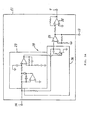
- Fig. 1 illustrates an example of the invention, as used with a vibrating gyroscope that detects angular velocity.
- Examples of the vibrators 4 are illustrated in Fig. 14 through Fig. 19. These vibrators 4 are formed of at least two piezo-electric elements 2 and 3 on the side surfaces of vibration members 1 having various cross-sectional shapes and resonance points and are given self-induced vibration.
- signal output terminal 9 of drive apparatus 60 is connected respectively to signal input terminals 11L and 11R of feedback amplifiers 10L and 10R.
- Feedback input terminals 12L and 12R of the feedback amplifiers 10L and 10R are respectively connected to one electrode each of piezo-electric elements 2 and 3.
- the other electrodes of piezo-electric elements 2 and 3 are connected to the inversion input terminal side of integrating amplifier 17 having feedback resistance Rfy, so that the voltage corresponding to the product of feedback resistance Rfy and the combined currents flowing through piezo-electric elements 2 and 3 are sent to output terminal 18.
- the output voltage from the output terminal 18 is sent to input terminal 14 of drive apparatus 60, so that vibrator 4 is given self-induced vibration.
- the outputs of feedback amplifiers 10L and 10R are supplied to differential amplifier 20, so that the Coriolis force arising from the angular velocity acting on vibrator 4 can be detected as voltage. Furthermore, feedback resistances Rf L and Rf R are respectively connected between the output side of each feedback amplifier 10L and 10R and the corresponding feedback input terminals 12L and 12R.
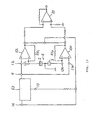
- Fig. 2A illustrates an example of the drive apparatus 60 shown in Fig. 1.
- This drive apparatus 60 has an automatic gain control circuit 28 ("AGC circuit"), non-inverting amplifier 25 and inverting amplifier 26.
- the AGC circuit 28 has a comparator 23 and a vibration controller 24.
- comparator 23 the input signal from input terminal 14 becomes direct current and is compared to a reference level.
- a direct current signal that corresponds to the comparison result is produced and supplied to vibration controller 24.
- Vibration controller 24 comprises, for example, an FET.
- An input signal from input terminal 14 is supplied to the source and drain paths of the FET.
- the output from comparator 23 is supplied to the gate of the FET to control the amplitude of the signal received from input terminal 14 based on the output of comparator 23.
- the AGC circuit 28 is not restricted to this example and can, for example, be constructed using an integrated multiplier.
- the output of the AGC circuit 28 is amplified to a predetermined value by non-inverting amplifier 25 and, then inverted at inverting amplifier 26 and supplied to signal output terminal 9.
- the inverting amplifier 26 inverts the signal from the non-inverting amplifier 25 and inserts vibrator 4 into the positive feedback loop, as already proposed by the present applicant in Japanese Patent Disclosure Hei 5-113336, hereby incorporated by reference.
- the drive apparatus 60 may comprise a drive signal output circuit 29.
- Drive signal output circuit 29 has a non-inverting amplifier 25 and an inverting amplifier 26.
- the signal output from the amplification controller 24 of AGC circuit 28 is amplified to a predetermined value at non-inverting amplifier 25 and then inverted at inverting amplifier 26 and supplied to signal output terminal 9.
- the amplitude of the signal is controlled by the amplification controller 24.
- the inverting amplifier 26 inverts the signal from non-inverting amplifier 25 and, as previously proposed by the applicant in Japanese Patent Disclosure Hei 5-11336, inserts vibrator 4 in the normal feedback loop.
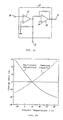
- the output of drive signal output circuit 29 varies according to the temperature dependencies of the equivalent resistances of vibrator 4. Therefore, the feedback resistance Rf 26 of inverting amplifier 26 contains a negative characteristic thermistor R T having the temperature dependence of the equivalent resistances of vibrator 4, for example, a temperature dependence corresponding to the temperature dependence of the equivalent resistance shown in Fig. 24.
- the voltage gain of inverting amplifier 26 simultaneously increases or decreases due to the temperature dependence of negative characteristic thermistor R T .
- the amount of decrease or increase in the current flowing through piezo-electric elements 2 and 3 are suppressed, and amplification changes in the signal supplied to input terminal 14 of drive apparatus 60 can be suppressed to a low degree.
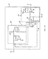
- Fig. 3 illustrates a second example of the invention.
- the output of integrating amplifier 17 at output terminal 18 is inversely amplified at inverting amplifier 19.
- the output of integrating amplifier 17 is inverted at inverting amplifier 19 and made in-phase with the drive signal.
- the output from inverting amplifier 19, i.e., a signal in-phase with the drive signal, is supplied via variable resistance VR to feedback input terminals 12L and 12R of feedback amplifiers 10L and 10R.
- This in-phase signal flows to feedback input terminals 12L and 12R after compensating for minute differences in the equivalent resistances of piezo-electric elements 2 and 3 with variable resistance VR.
- the remaining components are the same as in Fig. 1.
- At least one of the feedback resistances Rf L and Rf R of feedback amplifiers 10L and 10R is a variable resistance.
- variable resistance VR minute differences in the equivalent resistances of piezo-electric elements 2'and 3 are compensated for by variable resistance VR.
- the current flowing in feedback resistances Rf L and Rf R is made equal to the current of the damping capacity of piezo-electric elements 2 and 3.
- variable feedback resistance Rf R Minute differences in the damping capacity of piezo-electric elements 2 and 3 are compensated for by variable feedback resistance Rf R , so that the respective products of the imaginary part of the current corresponding to the respective currents flowing in the damping capacity of piezo-electric elements 2 and 3 and the corresponding feedback resistance Rf L and variable feedback resistance Rf R , i.e., the voltage of the imaginary part of the current, become equal.
- the current flowing into feedback input terminals 12L and 12R of feedback amplifiers 10L and 10R corresponds to the current flowing in the equivalent resistances of the respective piezo-electric elements 2 and 3 and varies in correspondence to their temperature dependencies. Therefore, only current corresponding to the Coriolis force flows in feedback resistances Rf L and Rf R of feedback amplifiers 10L and 10R. Consequently, formations of low voltage in feedback amplifiers 10L and 10R can be effectively decreased. Since the phase component corresponding to input angular velocity can also be effectively amplified, it becomes possible to detect angular velocity at higher accuracy in addition to the effect of Example 1.
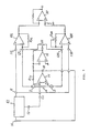
- Fig. 4 illustrates Example 3 of the invention.
- the system of this example uses a drive apparatus 61 having a compensation signal output terminal 13 that outputs the compensation signal of the damping capacity of vibrator 4. This compensation signal is combined with the other electrode signals of piezo-electric elements 2 and 3 via capacitor Cc.
- the output of integrating amplifier 17 and the drive signal from drive apparatus 61 are supplied to differential amplifier 22 and differentially amplified.
- the output of differential amplifier 22 is supplied via variable amplifier VR to feedback input terminals 12L and 12R in the same manner as in Fig. 3.
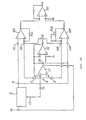
- Fig. 5A illustrates an example of a drive apparatus 61 shown in Fig. 4.
- the drive apparatus 61 also supplies a compensation signal to compensation signal output terminal 13.
- the rest of this system is the same as Fig. 2.
- Their amplitude ratio is appropriately set by inverting amplifier 26.
- the imaginary parts of the currents flowing in piezo-electric elements 2 and 3, relative to the respective damping capacities Cd, are extinguished by the compensation signal supplied via capacitor Cc, so that the output of integrating amplifier 17 is only the real part of the currents flowing in piezo-electric elements 2 and 3. Consequently, the voltage gain of integrating amplifier 17 maximizes at the mechanical series resonance frequency f s of vibrator 4, so that it is possible to impart self-induced vibration to vibrator 4 by stabilizing it at a frequency in accurate agreement with the mechanical series resonance frequency f s .
- the vibrator 4 oscillates at or near its resonant frequency.
- the self-induced vibration at the mechanical series resonance frequency f s can be made more stabilized by using a capacitor Cc having a temperature dependence corresponding to the temperature dependence of the damping capacities Cd of vibrator 4.
- the output of integrating amplifier 17 is only the real part of the currents flowing in piezo-electric elements 2 and 3. Therefore, when the equivalent resistances of piezo-electric elements 2 and 3 increase or decrease, the currents flowing through piezo-electric elements 2 and 3 decrease or increase correspondingly, so that the level of the output signal of comparator 23 in drive apparatus 61 falls or rises. Therefore, the resistance between the source and drain of the FET of vibration controller 24 increases or decreases, so that the size of the signal supplied to inverting amplifier 26 is increased or decreased until the signal input into comparator 23 reaches a fixed value corresponding to the reference level.
- the output voltage of integrating amplifier 17, i.e., the combined current flowing through piezo-electric elements 2 and 3 from which current corresponding to the damping capacity has been subtracted, is held fixed, so that the equivalent resistance of vibrator 4 in the self-induc'ed vibration direction is apparently fixed.
- the equivalent resistance to vibration in the sensitivity direction of vibrator 4 formed by the same piezo-electric elements 2 and 3 is also apparently held fixed, so that the input angular velocity detection sensitivity becomes fixed regardless of changes in ambient temperature, thereby making highly accurate detection possible.
- a drive apparatus 61 for Fig. 4 is shown in Fig. 5B.
- feedback resistance Rf 26 of inverting amplifier 26 has a negative characteristic thermistor R T which has a temperature dependence differing from the temperature dependence of the damping capacity of vibrator 4, so that the output of inverting amplifier 26 varies differently from the temperature dependence of the damping capacities of vibrator 4.
- the respective damping capacities of piezo-electric elements 2 and 3 increase or decrease because of changes in ambient temperature
- the current flowing through the damping capacity sides of piezo-electric elements 2 and 3 increases or decreases accordingly, while the voltage gain of inverting amplifier 26 simultaneously decreases or increases. Consequently, the current flowing in the damping capacities of piezo-electric elements 2 and 3 becomes unequal to the current supplied from compensation signal output terminal 13 via capacitor Cc and is, therefore, extinguished.
- the temperature dependence of the currents respectively flowing through the equivalent resistance sides and damping capacity sides of vibrator 4 have similar tendencies, so that the amounts of increase or decrease in current flowing through the equivalent resistance sides are suppressed and amplitude changes in the signal supplied to input terminal 14 of drive apparatus 61 are also suppressed to a low degree. Consequently, changes in the output of comparator 23 caused by temperature changes become small, so that the amount of change in resistance between the source and drain of the FET of amplitude controller 24 becomes small. As a result changes in current become small even under wide changes in the equivalent resistances of vibrator 4 over a broad range, so that the operational range of AGC circuit 28 is substantially widened.
- the imaginary part of the current flowing in piezo-electric elements 2 and 3 is effectively extinguished by a compensation signal corresponding to the temperature dependence of the damping capacity, so that it is held apparently fixed even with regard to the equivalent resistance to vibration in the sensitivity direction of vibrator 4 having the same piezo-electric elements 2 and 3.
- the voltage gain of differential amplifier 17 maximizes at the mechanical series resonance frequency f s of vibrator 4. Since vibrator 4 is given self-induced vibration stabilized at a frequency in exact agreement with the mechanical series resonance frequency f s , the detection sensitivity for input angular velocity becomes fixed regardless of ambient temperature changes, thus, making highly accurate detection possible.
- Fig. 6 illustrates Example 4 of the invention.
- This example is similar to Fig. 1 except that it replaces drive apparatus 60 with drive apparatus 61 having the compensation signal output terminal 13 as shown in Figs. 5A or B.
- This compensation signal is combined with the signals of the electrodes on the other sides of piezo-electric elements 2 and 3 via capacitor Cc. Consequently, as in Example 3, the equivalent resistances for vibration in the sensitivity direction of vibrator 4 formed of the same piezo-electric elements 2 and 3 can be held apparently fixed. Therefore, detection sensitivity for input angular velocity can be fixed regardless of changes in ambient temperature, thereby making it possible to detect angular velocity at high accuracy.
- Fig. 7 illustrates Example 5 of the invention.
- This example is similar to Fig. 3 except that, instead of drive apparatus 60, it uses drive apparatus 61 having the compensation signal output terminal 13 as shown in Figs. 5A or B.
- This compensation signal flows through capacitor Cc and combines with the signals of the other two electrodes of piezo-electric elements 2 and 3.
- the equivalent resistances for vibration in the sensitivity direction of vibrator 4 formed of the same piezo-electric elements 2 and 3 can be held apparently fixed regardless of changes in ambient temperature.
- the detection sensitivity for input angular velocity can be fixed, so that it is possible to detect angular velocity at still higher accuracy.
- Fig. 8 illustrates Example 6 of the invention.
- This example is similar to Fig. 1 except that, instead of drive apparatus 60, it uses drive apparatus 61 having the compensation signal output terminal 13 as shown in Figs. 5 A and B.
- This compensation signal flows through capacitor Cc and combines with the signals of the other two electrodes of piezo-electric elements 2 and 3.
- the output of integrating amplifier 17 and the compensation signal are combined at integrating amplifier 21.
- the output of integrating amplifier 21 is supplied via variable resistance VR to feedback input terminals 12L and 12R, as in Fig. 3.
- Example 3 the equivalent resistances for vibration in the sensitivity direction of vibrator 4 formed of the same piezo-electric elements 2 and 3 can be held apparently fixed regardless of changes in ambient temperature, so that detection sensitivity for input angular velocity can be fixed. Minute differences in the equivalent resistances of piezo-electric elements 2 and 3 are compensated for by variable resistance VR as the combined signal output from amplifier 21 flows into feedback input terminals 12L and 12R. As a result, current flowing into feedback input terminals 12L and 12R varies in correspondence with the currents flowing in the equivalent resistances of piezo-electric elements 2 and 3 and with their temperature dependencies.
- phase component for the input angular velocity can be amplified.- It is also possible to fix the above described detection sensitivity and detect the angular velocity with still higher accuracy.
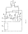
- Fig. 9 illustrates Example 7 of the invention.
- signal output terminal 9 of drive apparatus 62 is respectively connected with signal input terminals 11L and 11R of feedback amplifiers 10L and 10R.
- the signal input terminals 11L and 11R of feedback amplifiers 10L and 10R are connected to the respective single electrodes of piezo-electric elements 2 and 3, so that the drive signal is applied to the vibrator.
- the other electrodes of piezo-electric elements 2 and 3 are grounded.
- the outputs of feedback amplifiers 10L and 10R are combined and supplied to input terminal 14 of drive apparatus 62 so as to impart self-induced vibration to vibrator 4, while the outputs of the feedback amplifiers 10L and 10R are supplied to differential amplifier 20 so that the Coriolis force arising from the angular vibration acting on vibrator 4 can be detected as voltage.
- Fig. 10A illustrates an example of drive apparatus 62 as shown in Fig. 9.
- This drive apparatus 62 is similar to Fig. 2, except that it provides an inverting amplifier 30 before comparator 23 and the signal supplied at input terminal 14 is inverted and supplied to comparator 23.
- the feedback signal inputted to input terminal 14 of drive apparatus 62 is a combined signal of the outputs of feedback amplifiers 10L and 10R and is in-phase with the drive signal. Therefore, the feedback signal is inverted by inverting amplifier 30 and supplied to comparator 23.
- the output of feedback amplifiers 10L and 10R is a voltage which is the product of the currents flowing through piezo-electric elements 2 and 3 and the corresponding feedback resistances Rf L and Rf R .
- the voltage corresponds to the combined current flowing through piezo-electric elements 2 and 3. Consequently, when the amplitude of the drive signal outputted at drive apparatus 62 having AGC circuit 28 is controlled, so that the voltage is fixed, the equivalent resistances for vibration in the sensitivity direction of vibrator 4 formed of the same piezo-electric elements 2 and 3 can be held apparently fixed regardless of changes in ambient temperature. Therefore, detection sensitivity to input angular velocity can be fixed and the angular velocity can be detected at high accuracy in the same manner as in Example 1.
- Fig. 10B illustrates an alternative drive apparatus 62 having drive signal output circuit 29 as described for Figs. 2B and 5B.
- Fig. 11 illustrates Example 8 of the invention.
- drive apparatus 63 has compensation signal output terminal 13 that outputs the compensation signal of the damping capacity of vibrator 4. This compensation signal is combined with the outputs of feedback amplifiers 10L and 10R and is, thus, fed back to input terminal 14 of drive apparatus 63.
- Figs. 12A and B illustrate examples of the drive apparatus 63 shown in Fig. 11.
- This drive apparatus 63 is similar to the drive apparatus 62 shown in Figs. 10A and B.
- drive apparatus 63 also supplies the non-inverting amplifier 25 output to the non-inverting input terminal of feedback amplifier 27.
- Capacitor Cc is connected to the inverting input terminal of the feedback amplifier 27.
- the output of feedback amplifier 27 is supplied as a compensation signal to compensation signal output terminal 13.
- the drive signal output from signal output terminal 9 and the compensation signal output at compensation output terminal 13 differ in phase by 180° and their amplitude ratio is suitably set by inversion amplifier 26.
- the drive apparatus may have drive signal output circuit 29 with a feedback resistor Rf 26 and a thermistor R T , as described above.
- the feedback signal supplied to input terminal 14 has an imaginary part of the currents flowing in piezo-electric elements 2 and 3, relative to the respective damping capacities Cd.
- the imaginary part of the current is extinguished by the compensation current combined via capacitor Cc. Therefore, only the real number part of the currents flows in piezo-electric elements 2 and 3. Consequently, it is possible to impart self-induced vibration by stabilizing vibrator 4 at a frequency that is in accurate agreement with its mechanical series resonance frequency f s .
- the self-induced vibration at mechanical series resonance frequency f s can be further stabilized by using a capacitor Cc having a temperature dependence corresponding to the temperature dependence of damping capacities Cd of vibrator 4.
- the amplitude of the drive signal sent to signal output terminal 9 is controlled by the AGC circuit 28 and the level of the feedback signal supplied to its input terminal 14 is fixed. Therefore, the equivalent resistances for vibration in the sensitivity direction of vibrator 4, having the same piezo-electric elements 2 and 3, are held apparently fixed regardless of changes in ambient temperature. Consequently, detection sensitivity to input angular velocity is fixed and it is possible to detect the angular velocity at high accuracy.
- the combined current value of the currents flowing through a pair of piezo-electric elements is held fixed, thereby making it possible to hold the equivalent resistances of the vibrator apparently fixed regardless of ambient temperature changes. Consequently, the vibrator can be imparted self-induced vibration at a constantly fixed amplitude.
- a vibrating gyroscope that detects angular velocity using the same pair of piezo-electric elements, it is possible to fix the detection sensitivity in the self-induced vibration direction and the orthogonal direction regardless of changes in ambient temperature. It is also possible to detect input angular velocity constantly at high accuracy.
- the combined current comprising the currents flowing through a pair of piezo-electric elements and the current corresponding to the damping capacities subtracted, i.e., the real number part of the combined current, is held fixed, so that the equivalent resistances of the vibrator can be held apparently fixed regardless of ambient temperature changes. Consequently, the vibrator is given a more accurate self-induced vibration at a constantly fixed amplitude.
- a vibration gyroscope that detects angular velocity using the same pair of piezo-electric elements, it is possible to fix the detection sensitivity in the self-induced vibration direction and the orthogonal direction more accurately regardless of changes in ambient temperature. It is also possible to detect input angular velocity at still higher accuracy.
- the combined current value of the currents flowing through a pair of piezo-electric elements is held fixed by an AGC circuit.
- the voltage gain of the drive signal output circuit has a temperature dependence corresponding to the temperature dependence of the equivalent resistances of the vibrator.
- the AGC circuit has sufficient surplus even under changes in ambient temperature. Changes in current flowing in the vibrator are suppressed. It is possible to hold equivalent resistances of the AGC circuit apparently fixed. Consequently, the vibrator can be given stabilized self-induced vibration with no changes in amplitude.
- the combined current value of the currents flowing through a pair of piezo-electric elements with current corresponding to the damping capacities subtracted, i.e., the real part of the combined current is held fixed by the AGC circuit.
- a temperature dependence that differs from the temperature dependence of the damping capacities of the vibrator is imparted to the voltage gain of the drive signal output circuit, so that a sufficient surplus is given to the AGC circuit despite changes in ambient temperature. Changes in current flowing in the vibrator are suppressed. It is possible to hold the equivalent resistances apparently fixed. Consequently, the vibrator can be given stabilized self-induced vibration with no changes in amplitude.
Landscapes
- Engineering & Computer Science (AREA)
- Signal Processing (AREA)
- Physics & Mathematics (AREA)
- General Physics & Mathematics (AREA)
- Radar, Positioning & Navigation (AREA)
- Remote Sensing (AREA)
- Gyroscopes (AREA)
Description
- This invention relates to a vibration control apparatus used in a piezo-electric type vibrating gyroscope, and particularly to a vibration control apparatus having stabilized detection sensitivity for angular velocity in a wide range of temperatures and an automatic gain control circuit.
- An example of a conventional vibrating gyroscope is illustrated in Fig. 13. In this vibrating gyroscope, the
vibrator 4 has piezo-electric elements drive apparatus 6. The output side of thisdrive apparatus 6 is connected via another impedance element Z3 to capacitor element C. Therefore, drive signals from thedrive apparatus 6 are simultaneously applied to the piezo-electric elements - The outputs at the respective nodes of the impedance elements Z1 and Z2 and the piezo-
electric elements differential amplifier 7. The output from thedifferential amplifier 7 is fed back to thedrive apparatus 6 so that thevibrator 4 is self-vibrating. Additionally, the outputs at the respective nodes of impedance elements Z1 and Z2 and piezo-electric elements - An example of a
vibrator 4, shown in Fig. 14, has a square cross-sectional shape and has piezo-electric element 2 on one side surface la ofvibration member 1 having a resonance point and piezo-electric element 3 on another side surface 1b adjoining side surface la. Another example of avibrator 4, shown in Fig. 15, has piezo-electric elements vibration member 1. Another example of avibrator 4, shown in Fig. 16, has piezo-electric elements vibration member 1. Another example of avibrator 4, shown in Fig. 17, has the respective piezo-electric elements 2a and 2b on opposite side surfaces ofvibration member 1 and connects them in parallel so that they act essentially as one piezo-electric element 2, and has respective piezo-electric elements 3a and 3b on the other opposite sides and connects them in parallel so that they act essentially as one piezo-electric element 3. - Still another example of a
vibrator 4, shown in Fig. 18, has a triangular cross-sectional shape and has piezo-electric elements vibration member 1 having a resonance point. Another example of avibrator 4, shown in Fig. 19, has a circular cross-sectional shape and has piezo-electric elements vibrator member 1 having a resonance point. Thus, in all these examples, at least two piezo-electric elements are formed on the side surfaces of vibration members having various sectional shapes. Fig. 20 shows an equivalent circuit for a single piezo-electric element for the vibrators shown in Figs. 14 to 19, which is represented as a parallel resonance circuit with damping capacity Cd connected in parallel to a series resonance circuit comprising an inductor L1, a capacitor C1 and a resistance R1. Further, the vibrators comprising two piezo-electric elements vibration member 1 are represented equivalently in Fig. 21. - The conventional vibration gyroscope shown in Fig. 13 applies the drive signals from
drive apparatus 6 to piezo-electric elements electric elements electric elements vibrator 4. The frequency at which the output fromdifferential amplifier 7 is maximized and the mechanical series resonance frequency fs do not coincide. - In order to overcome such problems, the present applicant has already proposed, in Japanese Patent Application Hei 6-2364 and Japanese Patent Application Hei 6-10348, a vibration control apparatus that can impart self-induced vibration by stabilizing the vibrator at a frequency set to the mechanical series resonance frequency fs of the vibrator. In other words, the vibrator oscillates at or near its resonant frequency. When used with a vibrating gyroscope, the apparatus can also effectively decrease formation of low voltage and variations in voltage.
- Fig. 22 illustrates an example of a vibration control apparatus in the above patent applications of the applicant. This vibration control apparatus is one that controls vibrations in a
vibrator 4, as shown in Figs. 14 through 19. As discussed above, such avibrator 4 comprises at least one pair of piezo-electric elements vibration members 1 having varying cross-sectional shapes and resonance points.Signal output terminal 9 ofdrive apparatus 6 is respectively connected tosignal input terminals feedback amplifier 10L having feedback resistance RfL andfeedback amplifier 10R having feedback resistance RfR.Feedback input terminals feedback amplifiers electric elements electric elements signal output terminal 13 ofdrive apparatus 6 which outputs a compensation signal for the damping capacity ofvibrator 4, so that the compensation signal is combined with signals of the other electrodes of piezo-electric elements amplifier 17. Thesignal output terminal 18 is connected to theinput terminal 14 of thedrive apparatus 6, so that thevibrator 4 is given self-induced vibration. - The output of
integrating amplifier 17 and the drive signal atsignal output terminal 9 are supplied to thedifferential amplifier 22 and differentially amplified. The output of thedifferential amplifier 22 is supplied via variable resistance VR tofeedback input terminals feedback amplifiers electric elements feedback amplifiers differential amplifier 20, so that the Coriolis force arising from the angular velocity acting onvibrator 4 can be detected as voltage. Further, the respective feedback resistances RfL and RfR are connected between the output sides offeedback amplifiers feedback input terminals - Fig. 23 illustrates an example of the
drive apparatus 6 having the compensationsignal output terminal 13 as shown in Fig. 22. Thisdrive apparatus 6 has anon-inverting amplifier 15 and an invertingamplifier 16. The signal frominput terminal 14 is amplified at thenon-inverting amplifier 15. The output from thenon-inverting amplifier 15 is amplified at invertingamplifier 16 and then supplied to signaloutput terminal 9 as the drive signal. The output from thenon-inverting amplifier 15 is also supplied to thesignal output terminal 9 as a compensation signal. The drive signal and the compensation signal have a phase difference of 180°. The amplitude ratios of these signals are appropriately set by invertingamplifier 16. - With the vibration control apparatus illustrated in Fig. 22, the imaginary parts of the current flowing in piezo-
electric elements amplifier 17 becomes only the real part of the current flowing in piezo-electric elements amplifier 17 maximizes at the mechanical series resonance frequency fs ofvibrator 4, thereby, making it possible to impart self-induced vibration by stabilizingvibrator 4 at a frequency in accurate agreement with the mechanical series resonance frequency fs. In other words, the vibrator oscillates at or near its resonant frequency. Also, the self-induced vibration at mechanical series resonance frequency fs uses a capacitor Cc having a temperature dependence corresponding to the temperature dependence of dampling capacities Cd ofvibrator 4, so that further stabilization becomes possible. - As described above, the self-induced vibration is provided by at least one pair of piezo-electric elements without providing an independent piezo-electric element to obtain feedback output. Therefore, fluctuations in amplitude that accompany characteristic differences in the piezo-electric elements themselves will not occur, as in cases where a feedback piezo-electric element for self-induced vibration is furnished separately from the drive piezo-electric element. However, the currents flowing through the pair of feedback piezo-
electric elements vibrator 4 are determined by the impedance ofvibrator 4. Therefore, when the equivalent resistances and damping capacity of thevibrator 4 change due to ambient temperature, the currents change also. - With the above vibration control apparatus, fluctuations in damping capacity due to temperature changes are compensated for by capacitor Cc. Fluctuations or variations in equivalent resistances due to temperature changes are compensated for by supplying the output of
differential amplifier 22 tofeedback input terminals feedback amplifiers electric elements vibrator 4 varies inversely to the equivalent resistances. The amplitude of the vibration corresponding to the input angular velocity also varies correspondingly in the direction of self-induced vibration and in the orthogonal direction, so that detection sensitivity varies and detection accuracy can end up declining. - A further prior art driving circuit for a gyroscope is known from EP-A0 584 798. The described driving circuit comprises an oscillation circuit being connected to a feedback piezoelectric element and providing an amplified feedback signal to an AGC circuit via a phase-shifting circuit. The AGC circuit is further provided with a feedback signal from the auxiliary feedback piezoelectric element and provides a driving signal to the driving and detecting piezoelectric elements.
- It is the object of the invention to provide a vibration control apparatus which imparts stabilized self-induced vibration with no amplitude variations even under changes in ambient temperature. Consequently, when used with vibrating gyroscopes, the apparatus increases detection accuracy by eliminating the temperature dependence of input angular velocity detection sensitivity.
- In a first embodiment of the invention, the vibration control apparatus has a drive apparatus with an automatic gain control circuit and a vibrator having at least one pair of piezo-electric elements on the side surface of a vibration member having a resonance point. The drive apparatus imparts self-induced vibration to the vibrator, while the combined current value of the respective currents flowing through the pair of piezo-electric elements is held fixed.
- Since the combined current value of the currents passing through the pair of piezo-electric elements is held fixed, the equivalent resistances of the vibrator are apparently held fixed with no relation to ambient temperature changes. Consequently, the vibrator has self-induced vibration at a constantly fixed amplitude. When used-with a vibrating gyroscope that detects angular velocity using the same pair of piezo-electric elements, there is an effective suppression of temperature-induced variations in amplitude of vibration relative to input angular velocity in the direction of self-induced vibration and the orthogonal direction.
- In a second embodiment of the invention, the drive apparatus imparts self-induced vibration to the vibrator while the combined current value of currents flowing through the pair of piezo-electric elements from which combined currents corresponding to the damping capacity have been subtracted is held fixed.
- Since the combined current value of currents flowing through the pair of piezo-electric elements from which current corresponding to the damping capacity has been subtracted, i.e., the real part of the current, is held fixed, the equivalent resistances of the vibrator are apparently also held fixed with no relation to ambient temperature changes.. Consequently, the vibrator has more accurate self-induced vibration at a constantly fixed amplitude. Therefore, when used with a vibrating gyroscope that detects angular velocity by using the same pair of piezo-electric elements, the temperature-induced changes in vibration, which correspond to the input angular velocity in the self-induced vibration direction and in the orthogonal direction, are also suppressed with greater reliability.
- In a third embodiment of the invention, the vibration control apparatus has a drive apparatus which imparts self-induced vibration to a vibrator having at least one pair of piezo-electric elements on the side surface of a vibration member having a resonance point. A drive signal output circuit outputs a drive signal which is applied to the pair of piezo-electric elements. The voltage gain of the drive signal output circuit has a temperature dependence corresponding to the temperature dependencies of the equivalent resistances of the vibrator. An automatic gain control circuit holds the combined current of the currents flowing through the pair of piezo-electric elements fixed.
- Since the combined current value of the currents flowing through the pair of piezo-electric elements is held fixed by the automatic gain control circuit, stabilized self-induced vibration is imparted without variations in amplitude. The voltage gain of the drive signal output circuit has a temperature dependence corresponding to the temperature dependence of the equivalent resistances of the vibrator, so that even under variations in ambient temperature, variations in current flowing through the equivalent resistances of the vibrator are controlled. Consequently, the control range of the automatic gain control circuit is reduced and it is possible to broaden its operational range substantially.
- In a fourth embodiment of the invention, the drive signal output circuit has a voltage gain with a temperature dependence contrary to the temperature dependencies of the equivalent resistances of the vibrator. The automatic gain control circuit holds the combined current of the currents flowing through the pair of piezo-electric elements, with current corresponding to the damping capacity subtracted, fixed.
- Since the combined current of the currents flowing through a pair of piezo-electric elements from which current corresponding to the damping capacity has been subtracted, i.e., the real part of the combined current, is held fixed by the automatic gain control circuit, stabilized self-induced vibration is imparted without variations in amplitude. The voltage gain of the drive signal output circuit that outputs the drive signal applied to the pair of piezo-electric elements has a temperature dependence that does not correspond to the temperature dependence of the damping capacity of the vibrator. Therefore, even under variations in ambient temperature, variations in current flowing through the equivalent resistances of the vibrator are controlled. Consequently, the control range of the automatic gain control circuit is reduced and it is possible to broaden its operational range substantially.
- Current flowing through the piezo-electric elements varies depending on variations in the equivalent resistance values and damping capacity values of the vibrator. When imparting self-induced vibration to the vibrator by the pair of piezoelectric elements themselves, no variations in amplitude accompany the characteristic differences in the piezo-electric elements for drive and feedback, as in the case of self-induced vibration using respectively separate piezo-electric elements for drive and feedback. Therefore, the amplitude of self-induced vibration of the vibrator varies with the equivalent resistances and inverse numbers. Furthermore, when detecting angular velocity by using the same pair of piezo-electric elements, the detection sensitivity for angular velocity is determined by the amplitude of vibration in the self-induced vibration direction and in the orthogonal direction. However, in this case variations in these vibrations relate to the same pair of piezo-electric elements, so that when one amplitude direction is held fixed, the other orthogonal direction is also held fixed. Consequently, when the equivalent resistances of the vibrator are controlled so as to be held apparently fixed, it is also possible to hold the detection sensitivity for angular velocity fixed.
- The temperature dependencies of the equivalent resistances and damping capacity of the vibrator, as shown for example in Fig. 24, ordinarily have a tendency to be different, so that the temperature dependencies of the currents flowing in the equivalent resistance side and the damping capacity side of the vibrator have a tendency to be similar. Consequently, when the voltage gain of the drive signal output circuit has a temperature dependence differing from the temperature dependence of the damping capacity of the vibrator, the current flowing in the damping capacity side always has the same amplitude as the current of the damping capacity. Since the temperature dependencies of the current values flowing in the equivalent resistance side and the damping capacity side of the vibrator have a tendency to be similar, variations in current flowing in the equivalent resistances of the vibrator are suppressed. Consequently, the control range of the automatic gain control circuit is reduced and its operational range is broadened substantially.
- Fig. 1 illustrates a first example of the invention,
- Fig. 2A illustrates an example of the drive apparatus in Fig. 1,
- Fig. 2B illustrates an alternative example of the drive apparatus illustrated in Fig. 1,
- Fig. 3 illustrates a second example of the invention,
- Fig. 4 illustrates a third example of the invention,
- Fig. 5A illustrates an example of the drive apparatus shown in Fig. 4,
- Fig. 5B illustrates an alternative example of the drive apparatus shown in Fig. 4.,
- Fig. 6 illustrates a fourth example of the invention,
- Fig. 7 illustrates a fifth example of the invention,
- Fig. 8 illustrates a sixth example of the invention,
- Fig. 9 illustrates a seventh example of the invention,
- Fig. 10A illustrates an example of the drive apparatus shown in Fig. 9,
- Fig. 10B illustrates an alternative example of the drive apparatus shown in Fig. 9,
- Fig. 11 illustrates an eighth example of the invention,
- Fig. 12A illustrates an example of the drive apparatus shown in Fig. 11,
- Fig. 12B illustrates an alternative example of the drive apparatus shown in Fig. 11,
- Fig. 13 illustrates a conventional vibration control apparatus,
- Figs. 14 to 19 illustrate examples of vibrators that can be used with the invention,
- Fig. 20 illustrates an equivalent circuit of vibrator,
- Fig. 21 illustrates the display of the vibrator,
- Fig. 22 illustrates an example of a vibration control apparatus disclosed by inventor in related patent applications,
- Fig. 23 illustrates an example of the drive apparatus shown in Fig. 22, and
- Fig. 24 illustrates the temperature dependence of the equivalent resistance and damping capacity of the vibrator.
-
- The invention will be explained by examples, with reference to the drawings.
- Fig. 1 illustrates an example of the invention, as used with a vibrating gyroscope that detects angular velocity. Examples of the
vibrators 4 are illustrated in Fig. 14 through Fig. 19. Thesevibrators 4 are formed of at least two piezo-electric elements vibration members 1 having various cross-sectional shapes and resonance points and are given self-induced vibration. - In Fig. 1,
signal output terminal 9 ofdrive apparatus 60 is connected respectively to signalinput terminals feedback amplifiers Feedback input terminals feedback amplifiers electric elements electric elements amplifier 17 having feedback resistance Rfy, so that the voltage corresponding to the product of feedback resistance Rfy and the combined currents flowing through piezo-electric elements output terminal 18. The output voltage from theoutput terminal 18 is sent to inputterminal 14 ofdrive apparatus 60, so thatvibrator 4 is given self-induced vibration. The outputs offeedback amplifiers differential amplifier 20, so that the Coriolis force arising from the angular velocity acting onvibrator 4 can be detected as voltage. Furthermore, feedback resistances RfL and RfR are respectively connected between the output side of eachfeedback amplifier feedback input terminals - Fig. 2A illustrates an example of the
drive apparatus 60 shown in Fig. 1. Thisdrive apparatus 60 has an automatic gain control circuit 28 ("AGC circuit"),non-inverting amplifier 25 and invertingamplifier 26. TheAGC circuit 28 has acomparator 23 and avibration controller 24. Atcomparator 23 the input signal frominput terminal 14 becomes direct current and is compared to a reference level. A direct current signal that corresponds to the comparison result is produced and supplied tovibration controller 24.Vibration controller 24 comprises, for example, an FET. An input signal frominput terminal 14 is supplied to the source and drain paths of the FET. The output fromcomparator 23 is supplied to the gate of the FET to control the amplitude of the signal received frominput terminal 14 based on the output ofcomparator 23. TheAGC circuit 28 is not restricted to this example and can, for example, be constructed using an integrated multiplier. - The output of the
AGC circuit 28 is amplified to a predetermined value bynon-inverting amplifier 25 and, then inverted at invertingamplifier 26 and supplied to signaloutput terminal 9. The invertingamplifier 26 inverts the signal from thenon-inverting amplifier 25 and insertsvibrator 4 into the positive feedback loop, as already proposed by the present applicant in Japanese Patent Disclosure Hei 5-113336, hereby incorporated by reference. - As shown in Fig. 2B, the
drive apparatus 60 may comprise a drivesignal output circuit 29. Drivesignal output circuit 29 has anon-inverting amplifier 25 and an invertingamplifier 26. The signal output from theamplification controller 24 ofAGC circuit 28 is amplified to a predetermined value atnon-inverting amplifier 25 and then inverted at invertingamplifier 26 and supplied to signaloutput terminal 9. The amplitude of the signal is controlled by theamplification controller 24. Further, the invertingamplifier 26 inverts the signal fromnon-inverting amplifier 25 and, as previously proposed by the applicant in Japanese Patent Disclosure Hei 5-11336, insertsvibrator 4 in the normal feedback loop. - In this example, the output of drive
signal output circuit 29 varies according to the temperature dependencies of the equivalent resistances ofvibrator 4. Therefore, the feedback resistance Rf26 of invertingamplifier 26 contains a negative characteristic thermistor RT having the temperature dependence of the equivalent resistances ofvibrator 4, for example, a temperature dependence corresponding to the temperature dependence of the equivalent resistance shown in Fig. 24. - When the equivalent resistances of piezo-
electric elements electric elements comparator 23 indrive apparatus 60 falls or rises. By these means, the resistance between the FET source and drain ofamplitude controller 24 either increases or decreases, so that the size of the signal supplied to invertingamplifier 26 increases or decreases until the signal input tocomparator 23 reaches a fixed value corresponding to the reference level. - Also, when the current flowing in piezo-
electric elements amplifier 26 simultaneously increases or decreases due to the temperature dependence of negative characteristic thermistor RT. As a result, the amount of decrease or increase in the current flowing through piezo-electric elements terminal 14 ofdrive apparatus 60 can be suppressed to a low degree. - Consequently, changes in the output of
comparator 23 become small due to temperature changes. The amount of change in the resistance between the source and drain of the FET ofamplitude controller 24 also becomes small. As a result, the changes in current become small over a wide range of temperatures, even under wide changes in the equivalent resistances ofvibrator 4. It is possible to expand the operational range ofAGC circuit 28 substantially. - In this manner, since the output voltage of
cumulative amplifier 17, i.e., the combined current flowing through piezo-electric elements vibrator 4 in the self-induced vibration direction are apparently fixed. As a result, since the equivalent resistance to vibration in the sensitive direction ofvibrator 4 formed of the same piezo-electric elements - Fig. 3 illustrates a second example of the invention. In this embodiment, the output of integrating
amplifier 17 atoutput terminal 18 is inversely amplified at invertingamplifier 19. In other words, the output of integratingamplifier 17 is inverted at invertingamplifier 19 and made in-phase with the drive signal. The output from invertingamplifier 19, i.e., a signal in-phase with the drive signal, is supplied via variable resistance VR tofeedback input terminals feedback amplifiers feedback input terminals electric elements feedback amplifiers - In this example, minute differences in the equivalent resistances of piezo-electric elements 2'and 3 are compensated for by variable resistance VR. The real part of the current corresponding to the current flowing in the equivalent resistances of piezo-
electric elements feedback input terminals electric elements electric elements electric elements - When this is done, the current flowing into
feedback input terminals feedback amplifiers electric elements feedback amplifiers feedback amplifiers - Fig. 4 illustrates Example 3 of the invention. The system of this example uses a
drive apparatus 61 having a compensationsignal output terminal 13 that outputs the compensation signal of the damping capacity ofvibrator 4. This compensation signal is combined with the other electrode signals of piezo-electric elements amplifier 17 and the drive signal fromdrive apparatus 61 are supplied todifferential amplifier 22 and differentially amplified. The output ofdifferential amplifier 22 is supplied via variable amplifier VR tofeedback input terminals - Fig. 5A illustrates an example of a
drive apparatus 61 shown in Fig. 4. Besides supplying the output ofnon-inversion amplifier 25 to invertingamplifier 26, thedrive apparatus 61 also supplies a compensation signal to compensationsignal output terminal 13. The rest of this system is the same as Fig. 2. There is a 180° difference in phase between the drive signal output to signaloutput terminal 9 and the compensation signal output to compensationsignal output terminal 13. Their amplitude ratio is appropriately set by invertingamplifier 26. - In this example, the imaginary parts of the currents flowing in piezo-
electric elements amplifier 17 is only the real part of the currents flowing in piezo-electric elements amplifier 17 maximizes at the mechanical series resonance frequency fs ofvibrator 4, so that it is possible to impart self-induced vibration tovibrator 4 by stabilizing it at a frequency in accurate agreement with the mechanical series resonance frequency fs. In other words, thevibrator 4 oscillates at or near its resonant frequency. The self-induced vibration at the mechanical series resonance frequency fs can be made more stabilized by using a capacitor Cc having a temperature dependence corresponding to the temperature dependence of the damping capacities Cd ofvibrator 4. - The output of integrating
amplifier 17 is only the real part of the currents flowing in piezo-electric elements electric elements electric elements comparator 23 indrive apparatus 61 falls or rises. Therefore, the resistance between the source and drain of the FET ofvibration controller 24 increases or decreases, so that the size of the signal supplied to invertingamplifier 26 is increased or decreased until the signal input intocomparator 23 reaches a fixed value corresponding to the reference level. - In this manner, the output voltage of integrating
amplifier 17, i.e., the combined current flowing through piezo-electric elements vibrator 4 in the self-induc'ed vibration direction is apparently fixed. As a result, the equivalent resistance to vibration in the sensitivity direction ofvibrator 4 formed by the same piezo-electric elements - An alternative example of a
drive apparatus 61 for Fig. 4 is shown in Fig. 5B. Here, feedback resistance Rf26 of invertingamplifier 26 has a negative characteristic thermistor RT which has a temperature dependence differing from the temperature dependence of the damping capacity ofvibrator 4, so that the output of invertingamplifier 26 varies differently from the temperature dependence of the damping capacities ofvibrator 4. For example, when the respective damping capacities of piezo-electric elements electric elements amplifier 26 simultaneously decreases or increases. Consequently, the current flowing in the damping capacities of piezo-electric elements signal output terminal 13 via capacitor Cc and is, therefore, extinguished. - Also, the temperature dependence of the currents respectively flowing through the equivalent resistance sides and damping capacity sides of
vibrator 4 have similar tendencies, so that the amounts of increase or decrease in current flowing through the equivalent resistance sides are suppressed and amplitude changes in the signal supplied to inputterminal 14 ofdrive apparatus 61 are also suppressed to a low degree. Consequently, changes in the output ofcomparator 23 caused by temperature changes become small, so that the amount of change in resistance between the source and drain of the FET ofamplitude controller 24 becomes small. As a result changes in current become small even under wide changes in the equivalent resistances ofvibrator 4 over a broad range, so that the operational range ofAGC circuit 28 is substantially widened. - Also, the imaginary part of the current flowing in piezo-
electric elements vibrator 4 having the same piezo-electric elements - Consequently, the voltage gain of
differential amplifier 17 maximizes at the mechanical series resonance frequency fs ofvibrator 4. Sincevibrator 4 is given self-induced vibration stabilized at a frequency in exact agreement with the mechanical series resonance frequency fs, the detection sensitivity for input angular velocity becomes fixed regardless of ambient temperature changes, thus, making highly accurate detection possible. - Fig. 6 illustrates Example 4 of the invention. This example is similar to Fig. 1 except that it replaces
drive apparatus 60 withdrive apparatus 61 having the compensationsignal output terminal 13 as shown in Figs. 5A or B. This compensation signal is combined with the signals of the electrodes on the other sides of piezo-electric elements vibrator 4 formed of the same piezo-electric elements - Fig. 7 illustrates Example 5 of the invention. This example is similar to Fig. 3 except that, instead of
drive apparatus 60, it usesdrive apparatus 61 having the compensationsignal output terminal 13 as shown in Figs. 5A or B. This compensation signal flows through capacitor Cc and combines with the signals of the other two electrodes of piezo-electric elements - Consequently, in addition to the effect of Example 2, the equivalent resistances for vibration in the sensitivity direction of
vibrator 4 formed of the same piezo-electric elements - Fig. 8 illustrates Example 6 of the invention. This example is similar to Fig. 1 except that, instead of
drive apparatus 60, it usesdrive apparatus 61 having the compensationsignal output terminal 13 as shown in Figs. 5 A and B. This compensation signal flows through capacitor Cc and combines with the signals of the other two electrodes of piezo-electric elements amplifier 17 and the compensation signal are combined at integratingamplifier 21. The output of integratingamplifier 21 is supplied via variable resistance VR tofeedback input terminals - Consequently, as in Example 3, the equivalent resistances for vibration in the sensitivity direction of
vibrator 4 formed of the same piezo-electric elements electric elements amplifier 21 flows intofeedback input terminals feedback input terminals electric elements feedback amplifiers feedback amplifiers - Fig. 9 illustrates Example 7 of the invention. In this example,
signal output terminal 9 ofdrive apparatus 62 is respectively connected withsignal input terminals feedback amplifiers signal input terminals feedback amplifiers electric elements electric elements feedback amplifiers terminal 14 ofdrive apparatus 62 so as to impart self-induced vibration tovibrator 4, while the outputs of thefeedback amplifiers differential amplifier 20 so that the Coriolis force arising from the angular vibration acting onvibrator 4 can be detected as voltage. - Fig. 10A illustrates an example of
drive apparatus 62 as shown in Fig. 9. Thisdrive apparatus 62 is similar to Fig. 2, except that it provides an invertingamplifier 30 beforecomparator 23 and the signal supplied atinput terminal 14 is inverted and supplied tocomparator 23. In other words, while the feedback signal sent to the input terminal of the drive apparatus in the previous example had its phase inverted relative to the input signal by the output of integratingamplifier 17, here the feedback signal inputted to inputterminal 14 ofdrive apparatus 62 is a combined signal of the outputs offeedback amplifiers amplifier 30 and supplied tocomparator 23. - In this example, the output of
feedback amplifiers electric elements electric elements drive apparatus 62 havingAGC circuit 28 is controlled, so that the voltage is fixed, the equivalent resistances for vibration in the sensitivity direction ofvibrator 4 formed of the same piezo-electric elements alternative drive apparatus 62 having drivesignal output circuit 29 as described for Figs. 2B and 5B. - Fig. 11 illustrates Example 8 of the invention. In this example,
drive apparatus 63 has compensationsignal output terminal 13 that outputs the compensation signal of the damping capacity ofvibrator 4. This compensation signal is combined with the outputs offeedback amplifiers input terminal 14 ofdrive apparatus 63. - Figs. 12A and B illustrate examples of the
drive apparatus 63 shown in Fig. 11. Thisdrive apparatus 63 is similar to thedrive apparatus 62 shown in Figs. 10A and B. However, besides addingfeedback amplifier 27 and supplying the output ofnon-inverting amplifier 25 to invertingamplifier 26,drive apparatus 63 also supplies thenon-inverting amplifier 25 output to the non-inverting input terminal offeedback amplifier 27. Capacitor Cc is connected to the inverting input terminal of thefeedback amplifier 27. The output offeedback amplifier 27 is supplied as a compensation signal to compensationsignal output terminal 13. In other words, the drive signal output fromsignal output terminal 9 and the compensation signal output atcompensation output terminal 13 differ in phase by 180° and their amplitude ratio is suitably set byinversion amplifier 26. Alternatively, as shown in Fig. 10B, the drive apparatus may have drivesignal output circuit 29 with a feedback resistor Rf26 and a thermistor RT, as described above. - In this example, the feedback signal supplied to input terminal 14 has an imaginary part of the currents flowing in piezo-
electric elements electric elements vibrator 4 at a frequency that is in accurate agreement with its mechanical series resonance frequency fs. The self-induced vibration at mechanical series resonance frequency fs can be further stabilized by using a capacitor Cc having a temperature dependence corresponding to the temperature dependence of damping capacities Cd ofvibrator 4. - Also, in
drive apparatus 63 the amplitude of the drive signal sent to signaloutput terminal 9 is controlled by theAGC circuit 28 and the level of the feedback signal supplied to itsinput terminal 14 is fixed. Therefore, the equivalent resistances for vibration in the sensitivity direction ofvibrator 4, having the same piezo-electric elements - As described above, in the first embodiment of the invention, the combined current value of the currents flowing through a pair of piezo-electric elements is held fixed, thereby making it possible to hold the equivalent resistances of the vibrator apparently fixed regardless of ambient temperature changes. Consequently, the vibrator can be imparted self-induced vibration at a constantly fixed amplitude. When used with a vibrating gyroscope that detects angular velocity using the same pair of piezo-electric elements, it is possible to fix the detection sensitivity in the self-induced vibration direction and the orthogonal direction regardless of changes in ambient temperature. It is also possible to detect input angular velocity constantly at high accuracy.
- In the second embodiment of the invention, the combined current comprising the currents flowing through a pair of piezo-electric elements and the current corresponding to the damping capacities subtracted, i.e., the real number part of the combined current, is held fixed, so that the equivalent resistances of the vibrator can be held apparently fixed regardless of ambient temperature changes. Consequently, the vibrator is given a more accurate self-induced vibration at a constantly fixed amplitude. When used with a vibration gyroscope that detects angular velocity using the same pair of piezo-electric elements, it is possible to fix the detection sensitivity in the self-induced vibration direction and the orthogonal direction more accurately regardless of changes in ambient temperature. It is also possible to detect input angular velocity at still higher accuracy.
- As described above, in the third embodiment of the invention the combined current value of the currents flowing through a pair of piezo-electric elements is held fixed by an AGC circuit. The voltage gain of the drive signal output circuit has a temperature dependence corresponding to the temperature dependence of the equivalent resistances of the vibrator. As a result, the AGC circuit has sufficient surplus even under changes in ambient temperature. Changes in current flowing in the vibrator are suppressed. It is possible to hold equivalent resistances of the AGC circuit apparently fixed. Consequently, the vibrator can be given stabilized self-induced vibration with no changes in amplitude. When used with a vibrating gyroscope that detects angular velocity using the same pair of piezo-electric elements, it is possible to raise detection accuracy without temperature dependence of detection sensitivity relative to input angular velocity.
- In the fourth embodiment of the invention, the combined current value of the currents flowing through a pair of piezo-electric elements with current corresponding to the damping capacities subtracted, i.e., the real part of the combined current, is held fixed by the AGC circuit. At the same time, a temperature dependence that differs from the temperature dependence of the damping capacities of the vibrator is imparted to the voltage gain of the drive signal output circuit, so that a sufficient surplus is given to the AGC circuit despite changes in ambient temperature. Changes in current flowing in the vibrator are suppressed. It is possible to hold the equivalent resistances apparently fixed. Consequently, the vibrator can be given stabilized self-induced vibration with no changes in amplitude. When used with a vibrating gyroscope that detects angular velocity using the same pair of piezo-electric elements, it is possible to raise detection accuracy without temperature dependence of detection sensitivity relative to input angular velocity.
- Finally, the above described embodiments of the present invention are intended to be illustrative only. Numerous alternative embodiments may be devised by those skilled in the art without departing from the scope of the following claims.
Claims (4)
- Vibration control apparatus comprising a drive apparatus (60), a vibrator (4) having a vibration member having at least one side surface with a resonance point, and first and second piezoelectric elements (2, 3) on said at least one side surface, said drive apparatus (60) comprising an automatic gain control circuit (28) which imparts self-induced vibration to said vibrator (4)
characterized in that
said automatic gain control circuit (28) holds a combined current value of respective currents flowing through said first and second piezoelectric elements (2, 3) fixed. - Vibration control apparatus comprising a drive apparatus (60), a vibrator (4) having a vibration member having at least one side surface having a resonance point, and first and second piezoelectric elements (2, 3) on said side surface, said drive apparatus (60) comprising an automatic gain control circuit (28) which imparts self-induced vibration to said vibrator (4)
characterized in that
said automatic gain control circuit (28) holds a combined current value of currents flowing through said first and second piezoelectric elements (2, 3), from which current corresponding to a damping capacity has been subtracted, fixed. - Vibration control apparatus comprising:
a drive apparatus (60),
a vibrator (4) having a vibration member having at least one side surface with a resonance point,
first and second piezoelectric elements (2, 3) on said side surface, wherein said drive apparatus (60) imparts self-induced vibration to said vibrator (4)
characterized by
a drive signal output circuit (29) that outputs a drive signal applied to said first and second piezoelectric elements (2, 3) and has a voltage gain with a temperature dependence corresponding to temperature dependencies of equivalent resistances of said vibrator (4), and
an automatic gain control circuit (28) that holds a combined current value of currents flowing through said first and second piezoelectric elements (2, 3) fixed. - Vibration control apparatus comprising:
a drive apparatus (60),
a vibrator (4) having a vibration member having a side surface with a resonance point,
first and second piezoelectric elements (2, 3) on said side surface, wherein said drive apparatus (60) imparts self-induced vibration to said vibrator (4)
characterized by
a drive signal output circuit (29) that outputs a drive signal applied to said first and second piezoelectric elements (2, 3) and has a voltage gain with a temperature dependence contrary to temperature dependencies of equivalent resistances of said vibrator (4), and
an automatic gain control circuit (28) that holds a combined current value of currents flowing through said first and second piezoelectric elements (2, 3), with current corresponding to a damping capacity subtracted, fixed.
Applications Claiming Priority (6)
| Application Number | Priority Date | Filing Date | Title |
|---|---|---|---|
| JP15395394 | 1994-07-05 | ||
| JP153953/94 | 1994-07-05 | ||
| JP6153953A JPH0814913A (en) | 1994-07-05 | 1994-07-05 | Vibration controller |
| JP168142/94 | 1994-07-20 | ||
| JP6168142A JPH0829181A (en) | 1994-07-20 | 1994-07-20 | Vibration control apparatus |
| JP16814294 | 1994-07-20 |
Publications (2)
| Publication Number | Publication Date |
|---|---|
| EP0691524A1 EP0691524A1 (en) | 1996-01-10 |
| EP0691524B1 true EP0691524B1 (en) | 1999-11-24 |
Family
ID=26482421
Family Applications (1)
| Application Number | Title | Priority Date | Filing Date |
|---|---|---|---|
| EP95110433A Expired - Lifetime EP0691524B1 (en) | 1994-07-05 | 1995-07-04 | Vibration control apparatus having automatic gain control |
Country Status (3)
| Country | Link |
|---|---|
| US (1) | US5554904A (en) |
| EP (1) | EP0691524B1 (en) |
| DE (1) | DE69513451T2 (en) |
Families Citing this family (8)
| Publication number | Priority date | Publication date | Assignee | Title |
|---|---|---|---|---|
| JP3536497B2 (en) * | 1995-12-21 | 2004-06-07 | 株式会社デンソー | Vibration type angular velocity detector |
| US5902931A (en) * | 1996-04-26 | 1999-05-11 | Murata Manufacturing Co., Ltd. | Vibration gyroscope |
| JP2001174264A (en) * | 1999-12-21 | 2001-06-29 | Murata Mfg Co Ltd | Resonant element and vibration adjustment method thereof |
| JP2001201347A (en) * | 2000-01-19 | 2001-07-27 | Murata Mfg Co Ltd | Angular velocity sensor |
| US6553835B1 (en) * | 2000-09-15 | 2003-04-29 | Bei Technologies, Inc. | Inertial rate sensor and method with improved clocking |
| US7218029B2 (en) * | 2001-05-22 | 2007-05-15 | Texas Instruments Incorporated | Adjustable compensation of a piezo drive amplifier depending on mode and number of elements driven |
| JP4062293B2 (en) * | 2004-09-16 | 2008-03-19 | コニカミノルタホールディングス株式会社 | Drive device |
| CN111819833B (en) * | 2018-05-22 | 2022-05-13 | 株式会社村田制作所 | Vibration device and driving device |
Family Cites Families (6)
| Publication number | Priority date | Publication date | Assignee | Title |
|---|---|---|---|---|
| US4479098A (en) * | 1981-07-06 | 1984-10-23 | Watson Industries, Inc. | Circuit for tracking and maintaining drive of actuator/mass at resonance |
| FR2589247B1 (en) * | 1985-10-25 | 1988-06-10 | Labo Electronique Physique | APPARATUS FOR EXPLORING MEDIA BY ULTRASONIC ECHOGRAPHY INCLUDING A NETWORK OF PIEZOELECTIC TRANSDUCER ELEMENTS |
| US5349857A (en) * | 1988-08-12 | 1994-09-27 | Murata Manufacturing Co., Ltd. | Vibratory gyroscope |
| JPH0674774A (en) * | 1992-08-27 | 1994-03-18 | Murata Mfg Co Ltd | Drive circuit for gyro |
| JP3016986B2 (en) * | 1993-02-17 | 2000-03-06 | 三菱電機株式会社 | Vibrating gyroscope detection circuit |
| US5426970A (en) * | 1993-08-02 | 1995-06-27 | New Sd, Inc. | Rotation rate sensor with built in test circuit |
-
1995
- 1995-01-10 US US08/371,031 patent/US5554904A/en not_active Expired - Fee Related
- 1995-07-04 DE DE69513451T patent/DE69513451T2/en not_active Expired - Fee Related
- 1995-07-04 EP EP95110433A patent/EP0691524B1/en not_active Expired - Lifetime
Also Published As
| Publication number | Publication date |
|---|---|
| US5554904A (en) | 1996-09-10 |
| DE69513451T2 (en) | 2000-05-04 |
| DE69513451D1 (en) | 1999-12-30 |
| EP0691524A1 (en) | 1996-01-10 |
Similar Documents
| Publication | Publication Date | Title |
|---|---|---|
| EP0692698B1 (en) | Vibration control apparatus | |
| US5806364A (en) | Vibration-type angular velocity detector having sensorless temperature compensation | |
| US5434467A (en) | Vibrator and detector circuit for vibrating gyro | |
| JP3175489B2 (en) | Vibrating gyroscope and vibrating gyroscope inspection device | |
| US5554904A (en) | Vibration control apparatus having automatic gain control | |
| US20020100322A1 (en) | Vibrating gyroscope and temperature-drift adjusting method therefor | |
| US5594168A (en) | Vibration control apparatus having oscillation frequency regulation | |
| US5648608A (en) | Vibrating gyroscope detecting system | |
| EP0663584B1 (en) | Vibration control device for vibration of gyroscopes | |
| JPH05302833A (en) | DC amplification circuit of piezoelectric vibration gyro | |
| EP0658743B1 (en) | Vibrating gyroscope | |
| JP3395377B2 (en) | Vibration control device | |
| US5854428A (en) | Vibration gyroscope | |
| US5551292A (en) | Angular velocity detection circuit for vibratory gyroscopes | |
| JP3395394B2 (en) | Vibration control device | |
| JPH0829181A (en) | Vibration control apparatus | |
| JPH10206166A (en) | Vibration-type gyroscope | |
| US5824899A (en) | Vibratory gyroscope | |
| JPH09159459A (en) | Vibrating gyro | |
| JP2000292172A (en) | Driving and detecting device for piezoelectric vibrator | |
| US5922954A (en) | Vibration gyroscope and method for adjusting vibration-gyroscope characteristics | |
| JPH0814913A (en) | Vibration controller | |
| JPH09113277A (en) | Vibration gyro | |
| JPH04295716A (en) | Angular velocity sensor device | |
| JPH07243858A (en) | Vibration controller |
Legal Events
| Date | Code | Title | Description |
|---|---|---|---|
| PUAI | Public reference made under article 153(3) epc to a published international application that has entered the european phase |
Free format text: ORIGINAL CODE: 0009012 |
|
| AK | Designated contracting states |
Kind code of ref document: A1 Designated state(s): DE FR GB IT NL SE |
|
| 17P | Request for examination filed |
Effective date: 19960626 |
|
| RAP1 | Party data changed (applicant data changed or rights of an application transferred) |
Owner name: MITSUBISHI ELECTRIC CORPORATION |
|
| 17Q | First examination report despatched |
Effective date: 19980901 |
|
| GRAG | Despatch of communication of intention to grant |
Free format text: ORIGINAL CODE: EPIDOS AGRA |
|
| GRAG | Despatch of communication of intention to grant |
Free format text: ORIGINAL CODE: EPIDOS AGRA |
|
| GRAH | Despatch of communication of intention to grant a patent |
Free format text: ORIGINAL CODE: EPIDOS IGRA |
|
| GRAH | Despatch of communication of intention to grant a patent |
Free format text: ORIGINAL CODE: EPIDOS IGRA |
|
| GRAA | (expected) grant |
Free format text: ORIGINAL CODE: 0009210 |
|
| AK | Designated contracting states |
Kind code of ref document: B1 Designated state(s): DE FR GB IT NL SE |
|
| ITF | It: translation for a ep patent filed | ||
| REF | Corresponds to: |
Ref document number: 69513451 Country of ref document: DE Date of ref document: 19991230 |
|
| ET | Fr: translation filed | ||
| PLBE | No opposition filed within time limit |
Free format text: ORIGINAL CODE: 0009261 |
|
| STAA | Information on the status of an ep patent application or granted ep patent |
Free format text: STATUS: NO OPPOSITION FILED WITHIN TIME LIMIT |
|
| 26N | No opposition filed | ||
| REG | Reference to a national code |
Ref country code: GB Ref legal event code: IF02 |
|
| PGFP | Annual fee paid to national office [announced via postgrant information from national office to epo] |
Ref country code: GB Payment date: 20020703 Year of fee payment: 8 |
|
| PGFP | Annual fee paid to national office [announced via postgrant information from national office to epo] |
Ref country code: SE Payment date: 20020705 Year of fee payment: 8 |
|
| PGFP | Annual fee paid to national office [announced via postgrant information from national office to epo] |
Ref country code: FR Payment date: 20020709 Year of fee payment: 8 |
|
| PGFP | Annual fee paid to national office [announced via postgrant information from national office to epo] |
Ref country code: DE Payment date: 20020710 Year of fee payment: 8 |
|
| PGFP | Annual fee paid to national office [announced via postgrant information from national office to epo] |
Ref country code: NL Payment date: 20020730 Year of fee payment: 8 |
|
| PG25 | Lapsed in a contracting state [announced via postgrant information from national office to epo] |
Ref country code: GB Free format text: LAPSE BECAUSE OF NON-PAYMENT OF DUE FEES Effective date: 20030704 |
|
| PG25 | Lapsed in a contracting state [announced via postgrant information from national office to epo] |
Ref country code: SE Free format text: LAPSE BECAUSE OF NON-PAYMENT OF DUE FEES Effective date: 20030705 |
|
| PG25 | Lapsed in a contracting state [announced via postgrant information from national office to epo] |
Ref country code: NL Free format text: LAPSE BECAUSE OF NON-PAYMENT OF DUE FEES Effective date: 20040201 |
|
| PG25 | Lapsed in a contracting state [announced via postgrant information from national office to epo] |
Ref country code: DE Free format text: LAPSE BECAUSE OF NON-PAYMENT OF DUE FEES Effective date: 20040203 |
|
| GBPC | Gb: european patent ceased through non-payment of renewal fee |
Effective date: 20030704 |
|
| EUG | Se: european patent has lapsed | ||
| PG25 | Lapsed in a contracting state [announced via postgrant information from national office to epo] |
Ref country code: FR Free format text: LAPSE BECAUSE OF NON-PAYMENT OF DUE FEES Effective date: 20040331 |
|
| NLV4 | Nl: lapsed or anulled due to non-payment of the annual fee |
Effective date: 20040201 |
|
| REG | Reference to a national code |
Ref country code: FR Ref legal event code: ST |
|
| PG25 | Lapsed in a contracting state [announced via postgrant information from national office to epo] |
Ref country code: IT Free format text: LAPSE BECAUSE OF NON-PAYMENT OF DUE FEES;WARNING: LAPSES OF ITALIAN PATENTS WITH EFFECTIVE DATE BEFORE 2007 MAY HAVE OCCURRED AT ANY TIME BEFORE 2007. THE CORRECT EFFECTIVE DATE MAY BE DIFFERENT FROM THE ONE RECORDED. Effective date: 20050704 |