EP0691204B1 - Tuned entrance fang configuration for ink-jet printers - Google Patents
Tuned entrance fang configuration for ink-jet printers Download PDFInfo
- Publication number
- EP0691204B1 EP0691204B1 EP95302309A EP95302309A EP0691204B1 EP 0691204 B1 EP0691204 B1 EP 0691204B1 EP 95302309 A EP95302309 A EP 95302309A EP 95302309 A EP95302309 A EP 95302309A EP 0691204 B1 EP0691204 B1 EP 0691204B1
- Authority
- EP
- European Patent Office
- Prior art keywords
- ink
- channel
- entrance
- length
- increases
- Prior art date
- Legal status (The legal status is an assumption and is not a legal conclusion. Google has not performed a legal analysis and makes no representation as to the accuracy of the status listed.)
- Expired - Lifetime
Links
- 230000004888 barrier function Effects 0.000 claims description 22
- 238000013016 damping Methods 0.000 claims description 9
- 238000010438 heat treatment Methods 0.000 claims description 4
- 230000007423 decrease Effects 0.000 claims 3
- 238000013461 design Methods 0.000 description 29
- 238000010304 firing Methods 0.000 description 10
- 238000000034 method Methods 0.000 description 9
- 230000004044 response Effects 0.000 description 6
- 239000000758 substrate Substances 0.000 description 6
- 238000013459 approach Methods 0.000 description 4
- 239000000463 material Substances 0.000 description 4
- XUIMIQQOPSSXEZ-UHFFFAOYSA-N Silicon Chemical compound [Si] XUIMIQQOPSSXEZ-UHFFFAOYSA-N 0.000 description 3
- 230000000694 effects Effects 0.000 description 3
- 238000007639 printing Methods 0.000 description 3
- 229910052710 silicon Inorganic materials 0.000 description 3
- 239000010703 silicon Substances 0.000 description 3
- 230000008859 change Effects 0.000 description 2
- 238000005094 computer simulation Methods 0.000 description 2
- 230000000875 corresponding effect Effects 0.000 description 2
- 238000005530 etching Methods 0.000 description 2
- 239000011159 matrix material Substances 0.000 description 2
- 229920002120 photoresistant polymer Polymers 0.000 description 2
- 230000008569 process Effects 0.000 description 2
- 239000007921 spray Substances 0.000 description 2
- 238000012360 testing method Methods 0.000 description 2
- 238000005299 abrasion Methods 0.000 description 1
- 230000006978 adaptation Effects 0.000 description 1
- 238000006243 chemical reaction Methods 0.000 description 1
- 230000002596 correlated effect Effects 0.000 description 1
- 238000005520 cutting process Methods 0.000 description 1
- 238000013401 experimental design Methods 0.000 description 1
- 238000002474 experimental method Methods 0.000 description 1
- 230000006872 improvement Effects 0.000 description 1
- 238000007641 inkjet printing Methods 0.000 description 1
- 238000000608 laser ablation Methods 0.000 description 1
- 238000003754 machining Methods 0.000 description 1
- 238000004519 manufacturing process Methods 0.000 description 1
- 238000005259 measurement Methods 0.000 description 1
- 238000000691 measurement method Methods 0.000 description 1
- 230000007246 mechanism Effects 0.000 description 1
- 238000012986 modification Methods 0.000 description 1
- 230000004048 modification Effects 0.000 description 1
- 238000005457 optimization Methods 0.000 description 1
- 230000000007 visual effect Effects 0.000 description 1
Images

Classifications
-
- B—PERFORMING OPERATIONS; TRANSPORTING
- B41—PRINTING; LINING MACHINES; TYPEWRITERS; STAMPS
- B41J—TYPEWRITERS; SELECTIVE PRINTING MECHANISMS, i.e. MECHANISMS PRINTING OTHERWISE THAN FROM A FORME; CORRECTION OF TYPOGRAPHICAL ERRORS
- B41J2/00—Typewriters or selective printing mechanisms characterised by the printing or marking process for which they are designed
- B41J2/005—Typewriters or selective printing mechanisms characterised by the printing or marking process for which they are designed characterised by bringing liquid or particles selectively into contact with a printing material
- B41J2/01—Ink jet
- B41J2/135—Nozzles
-
- B—PERFORMING OPERATIONS; TRANSPORTING
- B41—PRINTING; LINING MACHINES; TYPEWRITERS; STAMPS
- B41J—TYPEWRITERS; SELECTIVE PRINTING MECHANISMS, i.e. MECHANISMS PRINTING OTHERWISE THAN FROM A FORME; CORRECTION OF TYPOGRAPHICAL ERRORS
- B41J2/00—Typewriters or selective printing mechanisms characterised by the printing or marking process for which they are designed
- B41J2/005—Typewriters or selective printing mechanisms characterised by the printing or marking process for which they are designed characterised by bringing liquid or particles selectively into contact with a printing material
- B41J2/01—Ink jet
- B41J2/135—Nozzles
- B41J2/14—Structure thereof only for on-demand ink jet heads
- B41J2/14016—Structure of bubble jet print heads
- B41J2/14032—Structure of the pressure chamber
- B41J2/1404—Geometrical characteristics
-
- B—PERFORMING OPERATIONS; TRANSPORTING
- B41—PRINTING; LINING MACHINES; TYPEWRITERS; STAMPS
- B41J—TYPEWRITERS; SELECTIVE PRINTING MECHANISMS, i.e. MECHANISMS PRINTING OTHERWISE THAN FROM A FORME; CORRECTION OF TYPOGRAPHICAL ERRORS
- B41J2/00—Typewriters or selective printing mechanisms characterised by the printing or marking process for which they are designed
- B41J2/005—Typewriters or selective printing mechanisms characterised by the printing or marking process for which they are designed characterised by bringing liquid or particles selectively into contact with a printing material
- B41J2/01—Ink jet
- B41J2/135—Nozzles
- B41J2/14—Structure thereof only for on-demand ink jet heads
- B41J2/14016—Structure of bubble jet print heads
- B41J2/14145—Structure of the manifold
-
- B—PERFORMING OPERATIONS; TRANSPORTING
- B41—PRINTING; LINING MACHINES; TYPEWRITERS; STAMPS
- B41J—TYPEWRITERS; SELECTIVE PRINTING MECHANISMS, i.e. MECHANISMS PRINTING OTHERWISE THAN FROM A FORME; CORRECTION OF TYPOGRAPHICAL ERRORS
- B41J2/00—Typewriters or selective printing mechanisms characterised by the printing or marking process for which they are designed
- B41J2/005—Typewriters or selective printing mechanisms characterised by the printing or marking process for which they are designed characterised by bringing liquid or particles selectively into contact with a printing material
- B41J2/01—Ink jet
- B41J2/135—Nozzles
- B41J2/145—Arrangement thereof
- B41J2/15—Arrangement thereof for serial printing
-
- B—PERFORMING OPERATIONS; TRANSPORTING
- B41—PRINTING; LINING MACHINES; TYPEWRITERS; STAMPS
- B41J—TYPEWRITERS; SELECTIVE PRINTING MECHANISMS, i.e. MECHANISMS PRINTING OTHERWISE THAN FROM A FORME; CORRECTION OF TYPOGRAPHICAL ERRORS
- B41J2/00—Typewriters or selective printing mechanisms characterised by the printing or marking process for which they are designed
- B41J2/005—Typewriters or selective printing mechanisms characterised by the printing or marking process for which they are designed characterised by bringing liquid or particles selectively into contact with a printing material
- B41J2/01—Ink jet
- B41J2/135—Nozzles
- B41J2/14—Structure thereof only for on-demand ink jet heads
- B41J2002/14387—Front shooter
Definitions
- the present invention relates generally to ink-jet pens employed in thermal ink-jet printers, and, more particularly, to an improved printhead structure for introducing ink into the firing chambers from which the ink is ejected onto the print medium.
- the improved printhead structure improves damping of the pen, permitting all chambers to have substantially the same refill speed.
- the art of thermal ink-jet printing it is known to provide a plurality of electrically resistive elements on a common substrate for the purpose of heating a corresponding plurality of ink volumes contained in adjacent ink reservoirs leading to the ink ejection and printing process.
- the adjacent ink reservoirs are typically provided as cavities in a barrier layer attached to the substrate for properly isolating mechanical energy to predefined volumes of ink.
- the mechanical energy results from the conversion of electrical energy supplied to the resistive elements which creates a rapidly expanding vapor bubble in the ink above the resistive elements.
- a plurality of ink ejection orifices are provided above these cavities in a nozzle plate and provide exit paths for ink during the printing process.
- thermal ink-jet printheads it is necessary to provide a flow of ink to the thermal, or resistive, element causing ink drop ejection. This has been accomplished by manufacturing ink refill channels, or slots, in the substrate, ink barrier, or nozzle plate.
- the entrance length (the distance from the edge of the shelf to the channel entrance on an individual chamber basis) varies from 61 ⁇ m to 94 ⁇ m, with the nominal shelf length of 125 ⁇ m on one particular commercial thermal ink-jet pen.
- all chambers have a 90° tapered fang residing between the slot and the channel.
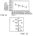
- the line width frequency testing has shown that the refill speed varies between chambers, with the 61 ⁇ m entrance length producing a "faster" chamber than the 94 ⁇ m entrance length.
- the nozzles with shortest entrance lengths are 350 Hz faster than those furthest from the slot.
- Existing thermal ink-jet pens include a print head for ejecting droplets of ink onto a print medium, said print head comprising:
- the different path lengths offer varying resistance to ink flow and thus vary the time it takes to refill each resistor firing chamber.
- the chamber cannot be fired in a predictable manner until refill takes place.
- these varying resistances vary the damping of the chamber. If a chamber is over-damped, it is a slower structure than optimum and if under-damped, it can cause nozzle instability resulting in spray, etc.
- US-A-5308442 and EP-A-0609012 (which forms part of the state of the art by virtue of Article 54(3) EPC) each describe methods of forming ink refill slots in thermal ink jet print heads of the type described above.
- the methods include laser ablation, mechanical abrasion, electromechanical machining or anisotropic etching of a silicon print head substrate.
- These references also disclose methods of etching the silicon shelf leading up to the inlet channel. While this solution certainly provides a satisfactory result, it is nonetheless a costly process step.
- the present invention provides a thermal ink-jet pen as defined in Claim 1 of the accompanying claims.
- Each individual chamber is optimally tuned by varying one or more specified dimensions of the ink flow path, depending on distance of the resistor from the edge of the ink refill slot.
- width of entrance to the ink feed channel for example, chambers close to the ink refill slot have comparatively smaller channel openings, whereas those further away from the ink refill slot have comparatively wider openings.
- the chambers with the longest entrance lengths will use the largest width, while those with the shortest entrance length will use the smallest width.
- the only change required to the existing thermal ink jet pen design is the barrier mask. By so altering the widths, the damping of the pen is improved. Tuning the widths to compensate for the resistor multiplex pattern allows for all the nozzles to have the same refill speed.
- the impedance of all chambers can be balanced so as to provide substantially the same refill speed for all nozzles.
- nozzle-to-nozzle frequency variation can be reduced.
- the widths of the nozzles closest to the slot are considerably narrower than the prior art design, while those furthest away are essentially unchanged.
- the difference (frequency variation) between the closest and furthest nozzles is reduced from 350 Hz (prior art design) to only 50 Hz.
- the thermal ink-jet pen of the present invention includes elements common to prior art pens, such as a printhead for ejecting droplets of ink onto a print medium, the printhead comprising (a) a plurality of resistive elements for heating ink supplied from a reservoir to generate the droplets of ink, (b) a plurality of nozzles through which the droplets of ink are ejected, with one nozzle associated with one resistive element, (c) a plurality of drop ejection chambers, each chamber enclosed on three sides by a barrier, each chamber having a floor supporting the resistive element, with the nozzle supported above the resistive element by said barrier, (d) a plurality of ink feed channels, each for supplying ink to one of the drop ejection chambers, and each ink feed channel provided with an entrance defined by a pair of projections on either side thereof, and (e) an ink refill slot operatively associated with the plurality of ink feed channels, the ink refill slot defined by an edge to provide a shelf
- the plurality of resistive elements is divided into sets, with a constant number of resistive elements per set, with each resistive element staggered a different distance from the edge.
- Each ink feed channel is provided with at least one different critical dimension (width of ink feed channel entrance, width of ink feed channel, length of ink feed channel, distance of resistor to the terminus of the channel.
- the width (entrance or channel) of the resistive element that is closer to the edge is narrower than the width of the resistive element that is further from the edge.
- the length of the channel of the resistive element that is closer to the edge is longer than the length of the channel of the resistive element that is further from the edge.
- the distance of resistor to the terminus of the channel for the resistive element that is closer to the edge is larger than that of the resistive element that is further from the edge.
- the tuned critical dimensions of the present invention allows optimization of the architecture across the pen, allowing all nozzles to operate at an optimum damping factor, which in turn causes less ink spray and more uniform printing.
- FIG. 1 a single resistor element 10 is shown in FIG. 1, comprising a resistor 12 situated at one end 14a of an ink feed channel 14 .
- Ink (not shown) is introduced at the opposite end 14b thereof, as indicated by arrow " A ", from a plenum, or ink refill slot, indicated generally at 16 .
- a nozzle 18 Associated with the resistor is a nozzle 18 , located above the resistor 12 in a nozzle plate 20 .
- the resistor 12 is energized by means not shown to fire a bubble of ink through the nozzle (i.e., normal to the surface of the resistor).
- the resistor 12 is located in a firing chamber 22 at the terminus 14a of the ink feed channel 14 .
- Both the chamber 22 and the ink feed channel 14 are formed in a barrier material 24 , which advantageously comprises a photoresist material.
- the photoresist material is processed, using conventional photolithographic techniques, to define the chamber 22 and ink feed channel 14 .
- Fangs, or lead-in lobes, 26 serve to prevent bubbles in the ink from residing in the ink refill slot area and act to guide any such bubbles into the firing chamber 22 , where they are purged during firing of the resistor 12 .
- the fangs terminate in fang tips 26a .
- Such fangs are disclosed and claimed in U.S. Patent 4,882,595, assigned to the same assignee as the present application.
- FIG. 2 depicts a prior art pen design, in which two rows of a plurality of resistors 12 are provided, one on either side of the ink refill slot 16 .
- all resistors 12 are staggered a different distance from the ink refill slot 16 , yet are supplied with ink from a common source of ink.
- the fang tips 26a are also staggered from the ink refill slot 16 in the prior art design.
- FIG. 3 provides a visual description of terms employed in this application.
- Entrance length L E is the distance from the edge 16a of the ink refill slot 16 to the beginning of the ink feed channel 14 .
- Shelf length L S is the distance from the resistor 12 to the edge 16a of the shelf 28a .
- Entrance width W E is measured between fang tips 26a
- channel width W C is the width of the ink feed channel 14 itself, as defined by the walls of the barrier 24 .
- Channel length L C is the length of the ink feed channel 14 , from its channel entrance 14b to its terminus 14a .
- Distance W F is the distance from the resistor 12 to the entrance to the resistor chamber 22 , defined by the terminus 14a of the channel 14 , also called the "front wall".
- the included angle ⁇ is relative to the edges of the fangs 26 .
- Shelf 28a refers to the top of the substrate 28 exposed by removal of the barrier material 24 in defining the fangs 26 and other features of the resistor element 10
- FIGs. 1 and 2 illustrate this approach, showing a plurality of firing chambers, each a different distance from the edge of the ink refill slot 16 , thereby providing a different entrance length L E .
- These prior art pen designs employ a repeating pattern of 13 staggered firing chambers 22 .
- the default, or prior art, pen design was included in this study for comparison purposes. As shown in FIG. 2, the default design has a constant 90° included angle on all of the entrances. Leveraging previous experiments on this family of pens, the nozzles closest to the ink refill slot 16 were expected to be faster than those furthest away. FIG. 2 illustrates that there is a constant 90° included angle on all of the default prior art entrances, regardless of entrance length L E .
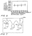
- FIG. 7 depicts the tuned configuration for a set of three staggered resistor elements.
- channel length L C can also be used to remove nozzle-to-nozzle variations. Longer channels produce slower chambers. Thus, nozzles closest to the shelf have long channels, while those further away should have short channels.
- sets of resistors 12 comprising 22 resistors per set, were designed in which the distance from the resistor to the front wall, W F , varied from 8 to 75.75 ⁇ m.
- the shelf length L S varied from 160 ⁇ m (at a front wall distance of 8 ⁇ m) to 123.75 (at a front wall distance of 75.75 ⁇ m).
- W F -1.865*L S + Constant.
- the value of the constant is 306.5.
- the model predicts a variation in refill frequency of about 3 kHz (for a nominally 8 kHz pen) where the first wall distance W F is kept constant at 8 ⁇ m and the shelf length L S is 130 ⁇ m.
- Examples 1-6 are directed to a pen design having a maximum shelf length of 130 ⁇ m
- Examples 7-12 are directed to a pen design having a maximum shelf length of 160 ⁇ m.
- the maximum and minimum shelf length L S are listed, along with the corresponding channel width W C , the front wall distance W F , and the channel length L C .
- the dimensions are in units of ⁇ m.
- the resulting pen refill frequency f in Hertz, is listed for each case.
- Example 1 No Compensation L S W C W F L C f 94 25 8 4 16,095 130 25 8 4 8,667
- Example 5 Channel Width and Front Wall Compensation L S W C W F L C f 94 25 34 4 13,043 130 51 8 4 9,358
- Example 6 Channel Width and Channel Length Compensation L S W C W F L C f 94 25 8 30 9,394 130 51 8 4 9,358
- Example 7 No Compensation L S W C W F L C f 124 25 8 4 9,389 160 25 8 4 6,260
- Example 11 Channel Width and Front Wall Compensation L S W C W F L C f 124 25 64 4 7,575 160 51 8 4 7,042
- Example 12 Channel Width and Channel Length Compensation L S W C W F L C f 124 25 8 23 7,060 160 51 8 4 7,042
- Example 13 Resistor Size Channel Width Local Refill Global Refill 52 ⁇ m 30 ⁇ m 6200 Hz 5200 Hz 52 ⁇ m 40 ⁇ m 6300 Hz 5350 Hz 52 ⁇ m 50 ⁇ m 6400 Hz 5450 Hz
- Example 14 Resistor Size Channel Width Local Refill Global Refill 55 ⁇ m 30 ⁇ m 5500 Hz 4650 Hz 55 ⁇ m 40 ⁇ m 5900 Hz 4700 Hz 55 ⁇ m 50 ⁇ m 6100 Hz 4750 Hz
- the nozzle frequency is substantially constant for all channel widths.
- This Table also shows for a larger resistor, more ink is ejected, resulting in a lower frequency response to refill the chamber. Further, for the larger resistor, the channel width has more of an effect on the refill frequency.
Landscapes
- Physics & Mathematics (AREA)
- Geometry (AREA)
- Particle Formation And Scattering Control In Inkjet Printers (AREA)
- Ink Jet (AREA)
Description
The relationship between refill time tR and channel length LC and channel width WC is given by
| Example 1: No Compensation | ||||
| LS | WC | WF | LC | f |
| 94 | 25 | 8 | 4 | 16,095 |
| 130 | 25 | 8 | 4 | 8,667 |
| Example 2: Channel Width Compensation | ||||
| LS | WC | WF | LC | f |
| 94 | 25 | 8 | 4 | 16,095 |
| 130 | 51 | 8 | 4 | 9,358 |
| Example 3: Front Wall Compensation | ||||
| LS | WC | WF | LC | f |
| 94 | 25 | 34 | 4 | 13,043 |
| 130 | 25 | 8 | 4 | 8,667 |
| Example 4: Channel Length Compensation | ||||
| LS | WC | WF | LC | f |
| 94 | 25 | 8 | 30 | 9,394 |
| 130 | 25 | 8 | 4 | 8,667 |
| Example 5: Channel Width and Front Wall Compensation | ||||
| LS | WC | WF | LC | f |
| 94 | 25 | 34 | 4 | 13,043 |
| 130 | 51 | 8 | 4 | 9,358 |
| Example 6: Channel Width and Channel Length Compensation | ||||
| LS | WC | WF | LC | f |
| 94 | 25 | 8 | 30 | 9,394 |
| 130 | 51 | 8 | 4 | 9,358 |
| Example 7: No Compensation | ||||
| LS | WC | WF | LC | f |
| 124 | 25 | 8 | 4 | 9,389 |
| 160 | 25 | 8 | 4 | 6,260 |
| Example 8: Channel Width Compensation | ||||
| LS | WC | WF | LC | f |
| 124 | 25 | 8 | 4 | 9,389 |
| 160 | 51 | 8 | 4 | 7,042 |
| Example 9: Front Wall Compensation | ||||
| LS | WC | WF | LC | f |
| 124 | 25 | 64 | 4 | 7,575 |
| 160 | 25 | 8 | 4 | 6,260 |
| Example 10: Channel Length Compensation | ||||
| LS | WC | WF | LC | f |
| 124 | 25 | 8 | 33 | 6,244 |
| 160 | 25 | 8 | 4 | 6,260 |
| Example 11: Channel Width and Front Wall Compensation | ||||
| LS | WC | WF | LC | f |
| 124 | 25 | 64 | 4 | 7,575 |
| 160 | 51 | 8 | 4 | 7,042 |
| Example 12: Channel Width and Channel Length Compensation | ||||
| LS | WC | WF | LC | f |
| 124 | 25 | 8 | 23 | 7,060 |
| 160 | 51 | 8 | 4 | 7,042 |
| Example 13: | |||
| Resistor Size | Channel Width | Local Refill | Global Refill |
| 52 µm | 30 µm | 6200 Hz | 5200 Hz |
| 52 µm | 40 µm | 6300 Hz | 5350 Hz |
| 52 | 50 µm | 6400 Hz | 5450 Hz |
| Example 14: | |||
| Resistor Size | Channel Width | Local Refill | |
| 55 µm | 30 µm | 5500 Hz | 4650 Hz |
| 55 µm | 40 µm | 5900 Hz | 4700 Hz |
| 55 | 50 µm | 6100 Hz | 4750 Hz |
Claims (9)
- A thermal ink-jet pen including a printhead for ejecting droplets of ink onto a print medium, said printhead comprising:(a) a plurality of resistive elements (12) for heating ink supplied from a reservoir to generate said droplets of ink;(b) a plurality of nozzles (18) through which said droplets of ink are ejected, with one nozzle (18) being associated with one resistive element (12);(c) a plurality of drop ejection chambers (22), each chamber (22) being enclosed on three sides by a barrier (24), each chamber (22) having a floor supporting said resistive element (12), with said nozzle (18) supported above said resistive element (12) by said barrier (24);(d) a plurality of ink feed channels (14), each for supplying ink to one said drop ejection chamber (22) through a terminus (14a) in a fourth side of said chamber, and each ink feed channel (14) being provided with a channel entrance defined by a pair of fangs (26) of the barrier (24) on either side thereof; and(e) an ink refill slot (16) operatively associated with said plurality of ink feed channels (14), said ink refill slot (16) being defined by an edge (16a) to provide a shelf (28a) from said edge (16a) to said plurality of ink feed channels (14),
wherein said plurality of resistive elements is divided into sets in which each resistive element (12) is staggered a different shelf length (LS) from said edge (16a), and wherein at least one of the following dimensional relationships applies within each said set:(A) the width (WE) of said channel entrance of said ink feed channel (14) increases as said shelf length (LS) increases;(B) the width (WC) of said ink feed channel (14) increases as said shelf length (LS) increases;(C) the length (LC) of said ink feed channel (14) decreases as said shelf length (LS) increases; or(D) the front wall distance (WF) from said resistive element (12) to the entrance to the chamber (22), defined by the terminus (14a) of the ink feed channel (14), decreases as said shelf length (LS) increases,
whereby the damping of the ink-jet pen is improved and all of the chambers (22) can be made to have substantially the same refill speed. - A thermal ink-jet pen according to claim 1 wherein said width of (WE) of said channel entrance is measured between the tips (26a) of the projections (26) defining the ink feed channel entrance.
- A thermal ink-jet pen according to claim 1 or 2 wherein said width (WE) of said channel entrance to said ink feed channel (14) increases as said shelf length (LS) increases.
- A thermal ink-jet pen according to any of claims 1 to 3 wherein said pen operates at a maximum frequency in Hz given by the following equation:
- A thermal ink-jet pen according to claim 1 wherein said width (WE) of said channel (14) is measured between walls of said barrier (24) defining a particular ink feed channel (14).
- A thermal ink-jet pen according to claim 5 wherein the width (WC) of said ink feed channel (14) increases as said shelf length (LS) increases.
- A thermal ink-jet pen according to any preceding claim wherein said length (LC) of said channel (14) is measured along a wall of said barrier (24) defining a particular ink feed channel (14).
- A thermal ink-jet pen according to claim 7 wherein the length (LC) of said ink feed channel (14) decreases as said shelf length (LS) increases.
- A thermal ink-jet pen according to any preceding claim wherein said front wall distance (WF) is measured from an edge of said resistive element (12) closest to said fourth side of said chamber (22).
Applications Claiming Priority (2)
| Application Number | Priority Date | Filing Date | Title |
|---|---|---|---|
| US272721 | 1994-07-08 | ||
| US08/272,721 US5519423A (en) | 1994-07-08 | 1994-07-08 | Tuned entrance fang configuration for ink-jet printers |
Publications (2)
| Publication Number | Publication Date |
|---|---|
| EP0691204A1 EP0691204A1 (en) | 1996-01-10 |
| EP0691204B1 true EP0691204B1 (en) | 1998-03-18 |
Family
ID=23040981
Family Applications (1)
| Application Number | Title | Priority Date | Filing Date |
|---|---|---|---|
| EP95302309A Expired - Lifetime EP0691204B1 (en) | 1994-07-08 | 1995-04-06 | Tuned entrance fang configuration for ink-jet printers |
Country Status (6)
| Country | Link |
|---|---|
| US (1) | US5519423A (en) |
| EP (1) | EP0691204B1 (en) |
| JP (1) | JPH0839803A (en) |
| KR (1) | KR100402567B1 (en) |
| DE (1) | DE69501801T2 (en) |
| TW (1) | TW261587B (en) |
Families Citing this family (36)
| Publication number | Priority date | Publication date | Assignee | Title |
|---|---|---|---|---|
| ES2203740T3 (en) | 1996-07-31 | 2004-04-16 | Canon Kabushiki Kaisha | HEAD OF BUBBLE JETS AND APPARATUS FOR BUBBLE JETS THAT USES THE SAME. |
| US5793393A (en) * | 1996-08-05 | 1998-08-11 | Hewlett-Packard Company | Dual constriction inklet nozzle feed channel |
| US6042222A (en) * | 1997-08-27 | 2000-03-28 | Hewlett-Packard Company | Pinch point angle variation among multiple nozzle feed channels |
| US6010208A (en) * | 1998-01-08 | 2000-01-04 | Lexmark International Inc. | Nozzle array for printhead |
| US6161923A (en) * | 1998-07-22 | 2000-12-19 | Hewlett-Packard Company | Fine detail photoresist barrier |
| US7216956B2 (en) * | 1998-10-16 | 2007-05-15 | Silverbrook Research Pty Ltd | Printhead assembly with power and ground connections along single edge |
| ATE367927T1 (en) | 1998-10-16 | 2007-08-15 | Silverbrook Res Pty Ltd | METHOD FOR PRODUCING A NOZZLE FOR AN INK JET PRINT HEAD |
| EP1024003B1 (en) * | 1999-01-29 | 2002-10-16 | Seiko Epson Corporation | Ink jet recording head with improved ink supply channels |
| US6238269B1 (en) * | 2000-01-26 | 2001-05-29 | Hewlett-Packard Company | Ink feed slot formation in ink-jet printheads |
| US6427597B1 (en) | 2000-01-27 | 2002-08-06 | Patrice M. Aurenty | Method of controlling image resolution on a substrate |
| DE60140411D1 (en) | 2000-09-06 | 2009-12-24 | Canon Kk | Ink jet recording head and method for its production |
| US6409318B1 (en) * | 2000-11-30 | 2002-06-25 | Hewlett-Packard Company | Firing chamber configuration in fluid ejection devices |
| US6502927B2 (en) * | 2000-12-28 | 2003-01-07 | Canon Kabushiki Kaisha | Ink jet recording head having two or more pillars for each nozzle |
| US6447104B1 (en) | 2001-03-13 | 2002-09-10 | Hewlett-Packard Company | Firing chamber geometry for inkjet printhead |
| US6364467B1 (en) * | 2001-05-04 | 2002-04-02 | Hewlett-Packard Company | Barrier island stagger compensation |
| US6565195B2 (en) * | 2001-05-04 | 2003-05-20 | Hewlett-Packard Development Company, L.P. | Feed channels of a fluid ejection device |
| US6561632B2 (en) * | 2001-06-06 | 2003-05-13 | Hewlett-Packard Development Company, L.P. | Printhead with high nozzle packing density |
| JP3927854B2 (en) * | 2002-04-23 | 2007-06-13 | キヤノン株式会社 | Inkjet recording head |
| US6540337B1 (en) | 2002-07-26 | 2003-04-01 | Hewlett-Packard Company | Slotted substrates and methods and systems for forming same |
| US6672712B1 (en) | 2002-10-31 | 2004-01-06 | Hewlett-Packard Development Company, L.P. | Slotted substrates and methods and systems for forming same |
| US7108352B2 (en) * | 2003-05-16 | 2006-09-19 | Canon Kabushiki Kaisha | Liquid-jet recording head |
| US7594328B2 (en) * | 2003-10-03 | 2009-09-29 | Hewlett-Packard Development Company, L.P. | Method of forming a slotted substrate with partially patterned layers |
| US6959979B2 (en) * | 2003-12-31 | 2005-11-01 | Lexmark International, Inc. | Multiple drop-volume printhead apparatus and method |
| TWI264376B (en) * | 2004-06-28 | 2006-10-21 | Benq Corp | Fluid injection device and method of fabricating the same |
| CN100569524C (en) | 2004-11-10 | 2009-12-16 | 佳能株式会社 | liquid discharge head |
| US7641317B2 (en) * | 2005-04-13 | 2010-01-05 | Canon Kabushiki Kaisha | Liquid discharge recording head and liquid discharge recording head cartridge including the same |
| US7427125B2 (en) * | 2005-04-15 | 2008-09-23 | Hewlett-Packard Development Company, L.P. | Inkjet printhead |
| US7517056B2 (en) * | 2005-05-31 | 2009-04-14 | Hewlett-Packard Development Company, L.P. | Fluid ejection device |
| US7431434B2 (en) * | 2005-05-31 | 2008-10-07 | Hewlett-Packard Development Company, L.P. | Fluid ejection device |
| JP4577226B2 (en) * | 2006-02-02 | 2010-11-10 | ソニー株式会社 | Liquid discharge head and liquid discharge apparatus |
| US7909434B2 (en) * | 2006-10-27 | 2011-03-22 | Hewlett-Packard Development Company, L.P. | Printhead and method of printing |
| US7712859B2 (en) * | 2007-07-30 | 2010-05-11 | Silverbrook Research Pty Ltd | Printhead with multiple nozzles sharing single nozzle data |
| US7794061B2 (en) * | 2007-07-30 | 2010-09-14 | Silverbrook Research Pty Ltd | Inkjet printhead with non-uniform nozzle chamber inlets |
| US7841697B2 (en) * | 2007-11-29 | 2010-11-30 | Silverbrook Research Pty Ltd | Printhead with redundant nozzle chamber inlets for minimizing effects of blockages |
| JP4975120B2 (en) * | 2010-02-08 | 2012-07-11 | キヤノン株式会社 | Inkjet recording head |
| WO2016068947A1 (en) * | 2014-10-30 | 2016-05-06 | Hewlett-Packard Development Company, L.P. | Ink jet printhead |
Family Cites Families (9)
| Publication number | Priority date | Publication date | Assignee | Title |
|---|---|---|---|---|
| DE439633C (en) * | 1927-01-13 | Albert Krummel | Dance figure toys | |
| US4338611A (en) * | 1980-09-12 | 1982-07-06 | Canon Kabushiki Kaisha | Liquid jet recording head |
| DE3102205A1 (en) * | 1981-01-23 | 1982-08-19 | Ringfeder Gmbh, 4150 Krefeld | DEVICE FOR REMOVING AND PUTTING IN A RESERVER WHEEL UNDER THE TIPPER BRIDGE IN TIPPERS ON TRUCK VEHICLES |
| US4882595A (en) * | 1987-10-30 | 1989-11-21 | Hewlett-Packard Company | Hydraulically tuned channel architecture |
| CA1300974C (en) * | 1987-10-30 | 1992-05-19 | Kenneth E. Trueba | Hydraulically tuned channel architecture |
| EP0439633A1 (en) * | 1990-01-02 | 1991-08-07 | Siemens Aktiengesellschaft | Print head for a thermally actuated ink-jet printer |
| US5274400A (en) * | 1992-04-28 | 1993-12-28 | Hewlett-Packard Company | Ink path geometry for high temperature operation of ink-jet printheads |
| EP0577383B1 (en) * | 1992-06-29 | 2003-10-08 | Hewlett-Packard Company, A Delaware Corporation | Thin film resistor printhead for thermal ink jet printers |
| US5308442A (en) * | 1993-01-25 | 1994-05-03 | Hewlett-Packard Company | Anisotropically etched ink fill slots in silicon |
-
1994
- 1994-07-08 US US08/272,721 patent/US5519423A/en not_active Expired - Lifetime
- 1994-12-29 TW TW083112336A patent/TW261587B/en not_active IP Right Cessation
-
1995
- 1995-04-06 EP EP95302309A patent/EP0691204B1/en not_active Expired - Lifetime
- 1995-04-06 DE DE69501801T patent/DE69501801T2/en not_active Expired - Lifetime
- 1995-07-07 KR KR1019950019914A patent/KR100402567B1/en not_active Expired - Fee Related
- 1995-07-07 JP JP7196177A patent/JPH0839803A/en not_active Withdrawn
Also Published As
| Publication number | Publication date |
|---|---|
| KR100402567B1 (en) | 2004-03-09 |
| JPH0839803A (en) | 1996-02-13 |
| EP0691204A1 (en) | 1996-01-10 |
| US5519423A (en) | 1996-05-21 |
| TW261587B (en) | 1995-11-01 |
| DE69501801T2 (en) | 1998-07-09 |
| KR960003969A (en) | 1996-02-23 |
| DE69501801D1 (en) | 1998-04-23 |
| HK1011956A1 (en) | 1999-07-23 |
Similar Documents
| Publication | Publication Date | Title |
|---|---|---|
| US5519423A (en) | Tuned entrance fang configuration for ink-jet printers | |
| US7926912B2 (en) | Liquid discharge method, liquid discharge head and liquid discharge apparatus | |
| US6543879B1 (en) | Inkjet printhead assembly having very high nozzle packing density | |
| JP3517305B2 (en) | Printer head of ink jet printer, method of supplying ink, and method of manufacturing printer head of ink jet printer | |
| EP1284860B1 (en) | Inkjet printing with air movement system | |
| US6331055B1 (en) | Inkjet printhead with top plate bubble management | |
| US20070291082A1 (en) | Drop on demand print head with fluid stagnation point at nozzle opening | |
| US20110205303A1 (en) | Fluid ejector structure | |
| EP0694398A1 (en) | Ink jet printhead with tuned firing chambers and multiple inlets | |
| JPH0764064B2 (en) | Ink Jet Print Head | |
| US6132033A (en) | Inkjet print head with flow control manifold and columnar structures | |
| US20030081071A1 (en) | Inkjet printhead having ink feed channels defined by thin-film structure and orifice layer | |
| US6779861B2 (en) | Enhanced dot resolution for inkjet printing | |
| HK1011956B (en) | Tuned entrance fang configuration for ink-jet printers | |
| JP3891561B2 (en) | Inkjet recording head | |
| TW201348008A (en) | Fluid ejection device | |
| JP3870062B2 (en) | Inkjet recording head | |
| EP0376922B1 (en) | Ink jet recording apparatus | |
| JP2888476B2 (en) | Thermal inkjet head | |
| JPH05293971A (en) | Ink jet recording apparatus | |
| EP0493039A2 (en) | Thermal ink jet printhead having an increased drop velocity | |
| JPH0781060A (en) | Inkjet head | |
| JPH07137293A (en) | Inkjet head, recording method, and inkjet recording apparatus | |
| JPH03132352A (en) | Ink jet recorder | |
| CN113272146A (en) | Fluid feed hole port size |
Legal Events
| Date | Code | Title | Description |
|---|---|---|---|
| PUAI | Public reference made under article 153(3) epc to a published international application that has entered the european phase |
Free format text: ORIGINAL CODE: 0009012 |
|
| AK | Designated contracting states |
Kind code of ref document: A1 Designated state(s): DE FR GB IT |
|
| 17P | Request for examination filed |
Effective date: 19960227 |
|
| 17Q | First examination report despatched |
Effective date: 19961014 |
|
| GRAG | Despatch of communication of intention to grant |
Free format text: ORIGINAL CODE: EPIDOS AGRA |
|
| GRAG | Despatch of communication of intention to grant |
Free format text: ORIGINAL CODE: EPIDOS AGRA |
|
| GRAH | Despatch of communication of intention to grant a patent |
Free format text: ORIGINAL CODE: EPIDOS IGRA |
|
| GRAH | Despatch of communication of intention to grant a patent |
Free format text: ORIGINAL CODE: EPIDOS IGRA |
|
| GRAA | (expected) grant |
Free format text: ORIGINAL CODE: 0009210 |
|
| AK | Designated contracting states |
Kind code of ref document: B1 Designated state(s): DE FR GB IT |
|
| REF | Corresponds to: |
Ref document number: 69501801 Country of ref document: DE Date of ref document: 19980423 |
|
| ET | Fr: translation filed | ||
| ITF | It: translation for a ep patent filed | ||
| PLBE | No opposition filed within time limit |
Free format text: ORIGINAL CODE: 0009261 |
|
| STAA | Information on the status of an ep patent application or granted ep patent |
Free format text: STATUS: NO OPPOSITION FILED WITHIN TIME LIMIT |
|
| 26N | No opposition filed | ||
| REG | Reference to a national code |
Ref country code: GB Ref legal event code: 732E |
|
| REG | Reference to a national code |
Ref country code: FR Ref legal event code: TP |
|
| REG | Reference to a national code |
Ref country code: FR Ref legal event code: CL |
|
| REG | Reference to a national code |
Ref country code: GB Ref legal event code: IF02 |
|
| REG | Reference to a national code |
Ref country code: GB Ref legal event code: 732E Free format text: REGISTERED BETWEEN 20120329 AND 20120404 |
|
| PGFP | Annual fee paid to national office [announced via postgrant information from national office to epo] |
Ref country code: IT Payment date: 20120424 Year of fee payment: 18 |
|
| PGFP | Annual fee paid to national office [announced via postgrant information from national office to epo] |
Ref country code: GB Payment date: 20130326 Year of fee payment: 19 |
|
| PGFP | Annual fee paid to national office [announced via postgrant information from national office to epo] |
Ref country code: DE Payment date: 20130322 Year of fee payment: 19 |
|
| PGFP | Annual fee paid to national office [announced via postgrant information from national office to epo] |
Ref country code: FR Payment date: 20130603 Year of fee payment: 19 |
|
| REG | Reference to a national code |
Ref country code: DE Ref legal event code: R119 Ref document number: 69501801 Country of ref document: DE |
|
| GBPC | Gb: european patent ceased through non-payment of renewal fee |
Effective date: 20140406 |
|
| REG | Reference to a national code |
Ref country code: DE Ref legal event code: R119 Ref document number: 69501801 Country of ref document: DE Effective date: 20141101 |
|
| REG | Reference to a national code |
Ref country code: FR Ref legal event code: ST Effective date: 20141231 |
|
| PG25 | Lapsed in a contracting state [announced via postgrant information from national office to epo] |
Ref country code: GB Free format text: LAPSE BECAUSE OF NON-PAYMENT OF DUE FEES Effective date: 20140406 Ref country code: DE Free format text: LAPSE BECAUSE OF NON-PAYMENT OF DUE FEES Effective date: 20141101 |
|
| PG25 | Lapsed in a contracting state [announced via postgrant information from national office to epo] |
Ref country code: FR Free format text: LAPSE BECAUSE OF NON-PAYMENT OF DUE FEES Effective date: 20140430 |
|
| PG25 | Lapsed in a contracting state [announced via postgrant information from national office to epo] |
Ref country code: IT Free format text: LAPSE BECAUSE OF NON-PAYMENT OF DUE FEES Effective date: 20140406 |