EP0691186B1 - Two-joint arm mechanism equipped with bi-articular driving means, and method for drive controlling each of driving means - Google Patents
Two-joint arm mechanism equipped with bi-articular driving means, and method for drive controlling each of driving means Download PDFInfo
- Publication number
- EP0691186B1 EP0691186B1 EP19950110425 EP95110425A EP0691186B1 EP 0691186 B1 EP0691186 B1 EP 0691186B1 EP 19950110425 EP19950110425 EP 19950110425 EP 95110425 A EP95110425 A EP 95110425A EP 0691186 B1 EP0691186 B1 EP 0691186B1
- Authority
- EP
- European Patent Office
- Prior art keywords
- arm
- driving means
- loading point
- backward
- movement
- Prior art date
- Legal status (The legal status is an assumption and is not a legal conclusion. Google has not performed a legal analysis and makes no representation as to the accuracy of the status listed.)
- Expired - Lifetime
Links
Images


Classifications
-
- B—PERFORMING OPERATIONS; TRANSPORTING
- B25—HAND TOOLS; PORTABLE POWER-DRIVEN TOOLS; MANIPULATORS
- B25J—MANIPULATORS; CHAMBERS PROVIDED WITH MANIPULATION DEVICES
- B25J9/00—Program-controlled manipulators
- B25J9/10—Program-controlled manipulators characterised by positioning means for manipulator elements
- B25J9/106—Program-controlled manipulators characterised by positioning means for manipulator elements with articulated links
- B25J9/1065—Program-controlled manipulators characterised by positioning means for manipulator elements with articulated links with parallelograms
-
- B—PERFORMING OPERATIONS; TRANSPORTING
- B25—HAND TOOLS; PORTABLE POWER-DRIVEN TOOLS; MANIPULATORS
- B25J—MANIPULATORS; CHAMBERS PROVIDED WITH MANIPULATION DEVICES
- B25J9/00—Program-controlled manipulators
- B25J9/02—Program-controlled manipulators characterised by movement of the arms, e.g. cartesian coordinate type
- B25J9/04—Program-controlled manipulators characterised by movement of the arms, e.g. cartesian coordinate type by rotating at least one arm, excluding the head movement itself, e.g. cylindrical coordinate type or polar coordinate type
- B25J9/046—Revolute coordinate type
-
- E—FIXED CONSTRUCTIONS
- E02—HYDRAULIC ENGINEERING; FOUNDATIONS; SOIL SHIFTING
- E02F—DREDGING; SOIL-SHIFTING
- E02F3/00—Dredgers; Soil-shifting machines
- E02F3/04—Dredgers; Soil-shifting machines mechanically-driven
- E02F3/28—Dredgers; Soil-shifting machines mechanically-driven with digging tools mounted on a dipper- or bucket-arm, i.e. there is either one arm or a pair of arms, e.g. dippers, buckets
- E02F3/36—Component parts
- E02F3/42—Drives for dippers, buckets, dipper-arms or bucket-arms
- E02F3/425—Drive systems for dipper-arms, backhoes or the like
Definitions
- the present invention relates to a two-joint arm mechanism which is preferably applied to a robot, a manipulator, an arm of a power shovel or the like which requires stiffness control of its loading point in operation of positioning various types of load by moving the load in a forward-backward direction, a upward-downward direction, and/or a diagonal direction with the load lifted and supported thereby, and a method for drive-controlling the two-joint arm mechanism, that is a method for drive-controlling each of the driving means.
- a two-joint arm mechanism in the field of a robot, a manipulator, an arm of a power shovel or the like, various types of those employing a two-joint arm mechanism have been proposed.
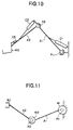
- those each comprising a first arm A1 pivoted at its rear end on a pivot pin P1, a second arm pivoted at its rear end on a pivot pin P2 at the forward end of the first arm A1, and a loading member for a load such as a grip or a bucket, wherein the first arm A1 and the second arm A2 are rotatable in either direction on the pivot pin P1 and P2, respectively.
- the directions of the pivot pins are horizontal or vertical. Accordingly, the arm mechanism is changed in its posture within a vertical plane or horizontal plane depending upon the directions of the pivot pins.
- the one illustrated in Fig.11 is of such a type that as driving means for rotating the two arms A1 and A2 in either direction on the respective pivot pins P1 and P2, motors M1 and M2 are mounted respectively on the pivot pins P1 and P2, and by selectively transmitting rotational forces in clockwise and counterclockwise directions caused by the motors M1 and M2 to the respective arms A1 and A2, the arms A1 and A2 are rotated in intended directions to enable the position of the loading member W1 to be changed freely.
- Fig.10 The one illustrated in Fig.10 is of such a type that extensible actuators C1 and C2 such as hydraulic cylinders are span-wise attached to the respective two arms A1 and A2, and by the extensional-retractive motions of the actuators C1 and C2, the arms A1 and A2 are rotated on the pivot pins P1 and P2, respectively, to enable the loading member W2 such as a bucket at the distal endpoint to carry out operation such as excavation.
- C3 is an actuator for controlling posture of the loading member W2.
- an object of the present invention to provide a two-joint arm mechanism equipped with a bi-articular driving means which is capable of controlling position, force and stiffness on a loading point of the forward end of a second arm independently, precisely and readily, and a method for drive-controlling all of driving means that is mono-articular driving mess as well as bi-articular driving means.
- the present invention has been made with a view to solving the above-mentioned problems.
- a two-joint arm mechanism equipped with a bi-articular driving means comprising:
- a method for controlling a two-joint arm mechanism equipped with a bi-articular driving means as well as mono-articular driving means comprising:
- Fig.1 is a side view of an embodiment of the arm mechanism according to the present invention.
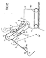
- Fig.2 is a side view of an embodiment in which the arm mechanism in Fig.1 is applied to a power shovel.
- Fig.3 is a side view of a embodiment of the two-joint arm mechanism, to which the method for drive-controlling each of the driving means in the present invention.
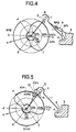
- Fig.4 is a radial diagrammatic view of output forces showing relationship between directions of movement of the loading point and patterns of output forces of the first driving means in the arm mechanism in Fig.3.
- Fig.5 is a radial diagrammatic view of output forces showing relationship between directions of movement of the loading point and patterns of output forces of the second driving means in the arm mechanism in Fig.3.
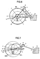
- Fig.6 is a radial diagrammatic view of output forces showing relationship between directions of movement of the loading point and patterns of output forces of the third driving means in the arm mechanism in Fig.3.
- Fig.7 is a radial diagrammatic view of output forces showing relationship between directions of movement of the loading point and patterns of output forces of the first driving means in the arm mechanism in Fig.3 with its posture having been changed.
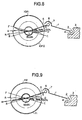
- Fig.8 is a radial diagrammatic view of output forces showing relationship between directions of movement of the loading point and patterns of output forces of the second driving means in the arm mechanism in Fig.3 with its posture having been changed.
- Fig.9 is a radial diagrammatic view of output forces showing relationship between directions of movement of the loading point and patterns of output forces of the third driving means in the arm mechanism in Fig.3 with its posture having been changed.
- Fig.10 is a side view of an example of a known arm mechanism.
- Fig.11 is a plan view of another example of a known arm mechanism.
- the reference numeral 1 represents a first arm, and a horizontal pivot pin 2 at the rear end 1a of the first arm is rotatably supported in a bearing 4 in a fixed base 3 to pivot the first arm.
- the reference numeral 5 represents a second arm, and a horizontal pivot pin 6 at the rear end 5a of the second arm is rotatably mounted in a bearing 7 formed at the forward end 1b of the first arm 1 to pivot the second arm.
- the reference numeral 8 represents a working member such as a grab or bucket which is mounted on the loading point 5b of the forward end of the second arm 5, and the above members from the first arm 1 to the loading member 8 constitute a two-joint arm mechanism in which the pivot pins 2 and 6 serve as joints.
- the arms 1 and 5 are independently rotatable on the pivot pins 2 and 6 in the clockwise-counterclocewise directions by advance-retract movements of an actuator, for example, a hydraulic cylinder 9 span-wise mounted between the middle of the first arm and the base 3 and a hydraulic cylinder 10 span-wise mounted between the forward end of the first arm 1 and the middle of the second arm 5, respectively.
- an actuator for example, a hydraulic cylinder 9 span-wise mounted between the middle of the first arm and the base 3 and a hydraulic cylinder 10 span-wise mounted between the forward end of the first arm 1 and the middle of the second arm 5, respectively.
- the reference numerals 9a and 10a represent piston rods
- the reference numerals 9b and 10b represent cylinder bodies
- the reference numerals 9c and 10c represent pistons
- the reference numerals 9d, 10d, 9e and 10e represent supply-discharge ports, respectively.
- the conventional two-joint arm mechanism is not capable of precisely and rapidly controlling force and stiffness on the loading point 5b at the forward end of the second arm 5 in relation to the base 3.
- a hydraulic cylinder 11 which serves as a driving means capable of acting simultaneously on both the arms 1 and 5 during rotation (s) of the arm(s) 1 and/or 5, thereby enabling force and stiffness developed at the loading point 5b in relation to the base 3 to be controlled independently of the first and second arms 1 and 5.
- a hydraulic cylinder 11 is mounted in such a manner that the forward end of a piston rod 11a and the rear end of a connecting rod 11b' so formed as to extend from the rear end of a cylinder body 11b are connected to the second arm 5 in the vicinity of the rear end thereof and the base 3, respectively, thereby controlling pressures of hydraulic fluids supplied to or discharged from hydraulic fluid supply-discharge ports 11d and 11e of the cylinder 11 during rotation(s) of arm(s) 1 and/or 5 against force(s) exerted on the forward and/or rear face(s) due to rotation(s) of the arm(s) 1 and/or 5.
- Fig.2 is a conceptional side view of a power shovel to which the two-joint arm mechanism of the present invention in Fig.1 is applied.
- a counterpart of the base 3 in Fig.1 is formed in a vehicle body 31 of the power shovel, and the bearing 7 and the pivot pin 6, which are mounted on the first arm 1 and the rear end 5a of the second arm 5 in Fig.1, respectively, are mounted on the converse members (arms 5 and 1).
- this embodiment is equivalent to the arm mechanism in Fig.1.
- the reference numeral 32 represents a crawler and the reference numeral 8a represents a driving means such as a cylinder for changing and retaining posture of a loading member 8.
- reference numerals 1'', 5'' and 5b'' represent positions to which the first arm 1, the second arm 5, the loading point 5b are alternatively moved.
- the first and second armns 1 and 5 are independently rotated by the output forces of the two mono-articular driving means 9 and 10 for the respective arms 1 and 5 to cause the arm mechanism as a whole to flex or extend, while the output force of the single bi-articular driving means capable of acting simultaneously on the arms 1 and 5 is controlled during the flexion or extension movement of the arm mechanism, thereby enabling position, force and stiffness of the loading point 5b at the forward end of the second arm 5 in relation to the base 3 to be controlled independently of the control of rotational forces and stiffnesses of the first arm 1 and the second arm 5.
- Fig.3 shows directions of movement of the loading point at the forward end 5b of the arm mechanism shown in Fig.1 (the same may apply to that in Fig.2), and the directions of movement are defined as follows.
- Direction A-D (first direction): directions shown by arrows on the line connecting the pivot pin 2 of the first arm 1 and the forward end 5b of the second arm 5 are defined as direction A and direction D.
- Direction B-E (second direction): directions shown by arrows on the line connecting the pivot pin 6 at the rear end 5a of the second arm 5 and the forward end 5b of the second arm 5 are defined as direction B and direction E.
- Direction C-F (third direction): directions shown by arrows on the line passing through the forward end 5b of the second arm 5 and in parallel with the line connecting the pivot pin 2 of the first arm 1 and the rear end 5a of the second arm 5 are defined as direction C and direction F.
- angles and positions of the first arm 1 and the second arm 5 change variously. Accordingly, the angles at which direction A-D (first direction), direction B-E (second direction) and direction C-F (third direction) intersect one another variously change according to the flexion and extension of the arm mechanism.
- driving force of each of the cylinders 9, 10 and 11 is determined according to the ratio of the arbitrary output force to the maximal output force.
- Fig.4 method for driving the hydraulic cylinder 9 as a first driving means, i.e., mode for exerting pressure 9P1 and pressure 9P2 depending upon the direction in which the loading point 5b' is moved.
- the output force is 100% between direction C and direction E in which include direction D, and 0% between direction F and direction B in which include direction A.
- the output force gradually reduced in an inversed sigmoidal curve from direction C to direction B, and gradually reduced in a sigmoidal curve from direction E to direction F.
- the output reduction pattern described above and the output increase pattern described below are those depicted by protting the outputs on the radial graphs in Figs.4 to 6. Accordingly, if the outputs are protted on a graph of a different type, a different pattern is obtained.
- the output force is 100% between direction F and direction B in which include direction A and 0% between direction C and direction E in which include direction D, as opposed to the pressure 9P1.
- the output force gradually increased in a sigmoidal curve from direction C to direction B, and gradually increased in an inversed sigmoidal curve from direction E to direction F.
- the sum of the pressure 9P1 and the pressure 9P2 is set to be 100% of the output force of the cylinder 9.
- Fig.5 method for driving the hydraulic cylinder 10 as a second driving means, i.e., mode for exerting pressure 10P1 and pressure 10P2 depending upon the direction in which the loading point 5b is moved.
- the output force is 100% between direction D and direction F in which include direction E and 0% between direction A and direction C in which include direction B.
- the pressure gradually reduced in an inversed sigmoidal curve from direction D to direction C, and gradually reduced in a sigmoidal curve from direction F to direction A.
- the pressure 10P2 when the loading point 5b is moved to direction B in the second direction, the pressure is 0% between direction D and direction F in which include direction E and 100% between direction A and direction C in which include direction B, as opposed to the pressure 10P1.
- the pressure gradually increased in a sigmoidal curve from direction D to direction C, and gradually increased in an inversed sigmoidal curve from direction F to direction A.
- the sum of the pressure 10P1 and the pressure 10P2 is set to be 100% of the output force of the cylinder 10.
- the present invention comprises controlling the driving of the hydraulic cylinder 11 as a third driving means, in parallel with the controlling the driving of the cylinders 9 and 10 in the above described mode. Accordingly, with reference to Fig.6, description will be made on the mode for controlling pressure P1 and pressure P2 depending upon the direction in which the loading point 5b is moved by the actions of the cylinders 9 and 10.
- the pressure P1 when the loading point 5b is moved to direction C in the third direction, the pressure is 100% between direction B and direction D in which include direction C and 0% between direction E and direction A in which include direction F.
- the pressure gradually reduced in an inversed sigmoidal curve from direction B to direction A, and gradually reduced in a sigmoidal curve from direction D to direction E.
- the pressure P2 when the loading point 5b is moved to direction F in the third direction, the pressure is 0% between direction B and direction D in which include direction C and 100% between direction E and direction A in which include direction F, as opposed to the pressure P1.
- the pressure gradually increased in a sigmoidal curve from direction B to direction A, and gradually increased in an inversed sigmoidal curve from direction D to direction E.
- the sum of the pressure P1 and the pressure P2 is set to be 100% of the output force of the cylinder 11.
- directions A-D, B-E and C-F indicating the directions of movement vary according to the flexion and extension of the arm mechanism, and the complementarily varying proportions between the pressures 9P1 and 9P2, 10P1 and 10P2, and P1 and P2 of the respective cylinders 9, 10, and 11 vary in the same proportions as in the changes in the directions of movement, as shown in Figs.7 to 9.
- the method for driving each of the cylinders 9, 10 and 11 has been derived from the studies in which an upper limb of a human being is considered as a two-joint link mechanism containing a shoulder joint and an elbow joint, and in conjunction with flexion and extention of the upper limb as a whole, analyses are performed on actions of a pair of antagonistic mono-articular muscles responsible for movement of the shoulder joint (which correspond to the pressures 9P1, 9P2 of the cylinder 9), a pair of antagonistic mono-articular muscles responsible for movement of the elbow joint (which correspond to the pressures 10P1, 10P2 of the cylinder 10), and a pair of antagonistic bi-articular muscles extending over the shoulder and elbow joints and responsible simultaneously for the movements of both the joints (which correspond to the pressures P1, P2 of the cylinder 11).
- the method of the present invention utilizes a driving method substantially in the same mode as in the shoulder and elbow joints of a human being for controlling each of the driving means of the two-joint arm mechanism equipped with the driving means acting simultaneously on the two-joints, i.e., the third bi-articular driving means which has not been incorporated in a conventional machine, robot or the like and is apparently redundant, thereby enabling movement of the loading point 5b at the forward end of the second arm 5 of the two-joint arm mechanism which is as smooth, rapid and precise as that of a human being to be realized.
- the present invention is constructed as described above, and accordingly, it comprises, in the two-joint arm mechanism, the two driving means which impart rotational forces independently to the arms, and the single driving means which imparts other forces exhibiting influence on the rotations of the arms caused by the output forces of the two driving means to both the arms simultaneously and which is extended over both the arms to move the loading point mounted on the forward end of the second arm to-and-fro, and the driving means are adapted to be drive-controlled simultaneously. Accordingly, there is attained a significant effect that force and stiffness of the loading point on the forward end of the second arm can be controlled independently of the first and second arms for moving and positioning the loading member relative to the fixed system such as a base. Such an effect has not been attained by a conventional two-joint arm mechanism.
- the drive-controlling method of the present invention is effectively applied to a robot, a manipulator, an arm of a power shovel or the like which requires stiffness control, as well as exhibits its effect when applied to an operating arm of a space robot, submarine search robot or the like, in particular, to an arm mechanism which is required to move smoothly, rapidly and precisely, such as an arm for operation in space.
Landscapes
- Engineering & Computer Science (AREA)
- Mechanical Engineering (AREA)
- Robotics (AREA)
- Mining & Mineral Resources (AREA)
- Civil Engineering (AREA)
- General Engineering & Computer Science (AREA)
- Structural Engineering (AREA)
- Manipulator (AREA)
Description
wherein two mono-articular driving means are respectively connected to the first arm and the second arm for independently exerting rotational forces on the respective arms in order to independently rotate the first arm and the second arm on pivot pins thereof to cause extension movement or flexion movement of the arm mechanism characterized in that, a single bi-articular driving means capable of acting simultaneously on both the arms is connectively mounted between the base and the second arm, and by simultaneously actuating these driving means, both the arms are rotated to move the loading point at the forward end of the second arm forward or backward relative to the base to effect positioning of the loading point at the forward end of the second arm.
wherein a first mono-articular driving means and a second mono-articular driving means are respectively connected to the first arm and the second arm for independently exerting driving forces for independently rotating the first arm and the second arm on pivot pins thereof, characterized in that a third bi-articular driving means capable of acting simultaneously on both the arms is connectively mounted between the base and the second arm, and by simultaneously actuating these driving means, both the arms are rotated to move the loading point at the forward end of the second arm forward or backward relative to the base to effect positioning of the loading point at the forward end of the second arm; the method comprising:
Claims (2)
- A two-joint arm mechanism equipped with a bi-articular driving means, the two-joint arm mechanism comprising:a first arm (1) pivoted at its rear end on a base (3) as a foundation,a second arm (5) pivoted at its rear end on the forward end of the first arm (1), anda loading member (8) mounted on the forward end of the second arm (5),
wherein two mono-articular driving means (9, 10) are respectively connected to the first arm (1) and the second arm (5) for independently exerting rotational forces on the respective arms (1, 5) in order to independently rotate the first arm (1) and the second arm (5) on pivot pins (2, 6) thereof to cause extension movement or flexion movement of the arm mechanism, characterized in that a single bi-articular driving means (11) capable of acting simultaneously on both the arms (1, 5) is connectively mounted between the base (3) and the second arm (5), and by simultaneously actuating these driving means (9, 10, 11), both the arms (1, 5) are rotated to move the loading point (5b) at the forward end of the second arm (5) forward or backward relative to the base (3) to effect positioning of the loading point (5b) at the forward end of the second arm (5). - A method for controlling a two-joint arm mechanism equipped with a bi-articular driving means, the two-joint arm mechanism comprising:a first arm (1) pivoted at its rear end on a base (3) as a foundation,a second arm (5) pivoted at its rear end on the forward end of the first arm (1), anda loading member (8) mounted on the forward end of the second arm (5),
wherein a first mono-articular driving means (9) and a second mono-articular driving means (10) are respectively connected to the first arm (1) and the second arm (5) for independently exerting driving forces for independently rotating the first arm (1) and the second arm (5) on pivot pins (2, 6) thereof, characterized in that a third bi-articular driving means (11) capable of acting simultaneously on both the arms (1, 5) is connectively mounted between the base (3) and the second arm (5), and by simultaneously actuating these driving means (9, 10, 11), both the arms are rotated to move the loading point (5b) at the forward end of the second arm (5) forward or backward relative to the base (3) to effect positioning of the loading point (5b) at the forward end of the second arm (5); the method comprising:dividing area of the movement of the loading point (5b) into direction A-D as a first direction on the line connecting the pivot pin (2) at the rear end of the first arm (1) and the forward end of the second arm (5), direction B-E as a second direction on the line passing along the second arm (5), and direction C-F as a third direction on the line passing through the loading point (5b) and in parallel with the first arm (1),controlling the first driving means (9) in such a manner that when the loading point (5b) is moved forward or backward in the range included by direction B-E and direction C-F and containing the first direction, the first driving means (9) is actuated at an output force of 100% in the direction of the movement, and when the loading point (5b) is moved forward or backward in the range included by direction B-E and direction C-F and without the first direction, the output force of the first driving means (9) in the direction of the forward or backward movement of the loading point is gradually reduced to 0%, and sum of the gradually reduced output forces in the directions of the forward and backward movements is set to be 100%,controlling the second driving means (10) in such a manner that when the loading point (5b) is moved forward or backward in the range included by direction A-Dand direction C-F and containing the second direction, the second driving means (10) is actuated at a output force of 100% in the direction of the movement, and when the loading point (5b) is moved forward or backward in the range included by direction A-D and direction C-F and without the second direction, the output force of the second driving means (10) in the direction of the forward or backward movement of the loading point (5b) is gradually reduced to 0%, and sum of the gradually reduced output forces in the directions of the forward and backward movements is set to be 100%, andcontrolling the third driving means (11) in such a manner that when the loading point (5b) is moved forward or backward in the range included by direction A-D and direction B-E and containing the third direction, the third driving means (11) is actuated at an output force of 100% in the direction of the movement, and when the loading point is moved forward or backward in the range included by direction A-D and direction B-E and without the second direction, the output force of the third driving means (11) in the direction of the forward or backward movement of the loading point (5b) is gradually reduced to 0%, and sum of the guradually reduced output forces in the directions of the forward and backward movements is set to be 100%.
Applications Claiming Priority (4)
| Application Number | Priority Date | Filing Date | Title |
|---|---|---|---|
| JP173148/94 | 1994-07-04 | ||
| JP17314894A JP3375202B2 (en) | 1994-07-04 | 1994-07-04 | Two-joint arm mechanism equipped with two-joint simultaneous drive source and operation control method thereof |
| JP107165/95 | 1995-04-07 | ||
| JP10716595A JPH08276386A (en) | 1995-04-07 | 1995-04-07 | Drive control method of each drive source in a two-joint arm mechanism equipped with a two-joint simultaneous drive source |
Publications (2)
| Publication Number | Publication Date |
|---|---|
| EP0691186A1 EP0691186A1 (en) | 1996-01-10 |
| EP0691186B1 true EP0691186B1 (en) | 1998-04-29 |
Family
ID=26447219
Family Applications (1)
| Application Number | Title | Priority Date | Filing Date |
|---|---|---|---|
| EP19950110425 Expired - Lifetime EP0691186B1 (en) | 1994-07-04 | 1995-07-04 | Two-joint arm mechanism equipped with bi-articular driving means, and method for drive controlling each of driving means |
Country Status (2)
| Country | Link |
|---|---|
| EP (1) | EP0691186B1 (en) |
| DE (1) | DE69502241T2 (en) |
Cited By (1)
| Publication number | Priority date | Publication date | Assignee | Title |
|---|---|---|---|---|
| CN109533080A (en) * | 2018-12-29 | 2019-03-29 | 北京工商大学 | Hexapod robot |
Families Citing this family (7)
| Publication number | Priority date | Publication date | Assignee | Title |
|---|---|---|---|---|
| CN103978481A (en) * | 2014-05-13 | 2014-08-13 | 苏州新协力特种工业模板有限公司 | Pneumatic mechanical grabbing device |
| CN107856029B (en) * | 2017-11-29 | 2021-08-10 | 长春工业大学 | Electro-hydraulic hybrid driving industrial mechanical arm structure and control system |
| CN108673479A (en) * | 2018-07-25 | 2018-10-19 | 温州大学 | industrial robot teaching system |
| CN113084865B (en) * | 2021-03-15 | 2022-11-22 | 上海园菱机械实业有限公司 | Mechanical arm structure and grinding and polishing mechanical arm |
| CN113635992B (en) * | 2021-06-15 | 2023-02-10 | 上海大学 | A bionic jumping leg driven by double-joint pneumatic artificial muscles |
| CN114102661B (en) * | 2021-11-17 | 2023-05-09 | 航天云机(北京)科技有限公司 | A dual-working mode robotic arm with high load-to-weight ratio |
| CN116280565B (en) * | 2023-04-21 | 2025-07-25 | 东莞市景华自动化科技有限公司 | Heavy in-mold labeling double-guiding pulling arm |
Family Cites Families (4)
| Publication number | Priority date | Publication date | Assignee | Title |
|---|---|---|---|---|
| GB1602213A (en) * | 1977-03-17 | 1981-11-11 | Motoda Denshi Kogyo Kk | Apparatus for transporting a load to a given spatial position |
| US4103791A (en) * | 1977-06-03 | 1978-08-01 | Harnischfeger Corporation | Shovel attachment means for hydraulic excavator |
| US4316697A (en) * | 1978-12-13 | 1982-02-23 | Kabushiki Kaisha Komatsu Seisakusho | Front-loading hydraulic excavator |
| JPS58126090A (en) * | 1982-01-18 | 1983-07-27 | 株式会社神戸製鋼所 | Multi-articulated arm mechanism |
-
1995
- 1995-07-04 DE DE1995602241 patent/DE69502241T2/en not_active Expired - Fee Related
- 1995-07-04 EP EP19950110425 patent/EP0691186B1/en not_active Expired - Lifetime
Cited By (1)
| Publication number | Priority date | Publication date | Assignee | Title |
|---|---|---|---|---|
| CN109533080A (en) * | 2018-12-29 | 2019-03-29 | 北京工商大学 | Hexapod robot |
Also Published As
| Publication number | Publication date |
|---|---|
| DE69502241T2 (en) | 1998-12-03 |
| DE69502241D1 (en) | 1998-06-04 |
| EP0691186A1 (en) | 1996-01-10 |
Similar Documents
| Publication | Publication Date | Title |
|---|---|---|
| US4353677A (en) | Wrist construction for industrial robots | |
| EP1684950B1 (en) | Parallel kinematics mechanism with a concentric spherical joint | |
| KR100888078B1 (en) | Joint structure of robot | |
| CN115503013A (en) | Multi-finger hydraulic humanoid manipulator | |
| US5484031A (en) | Leg structure for walking robot | |
| CN107584478B (en) | A three-degree-of-freedom parallel mechanism with rotatable axes | |
| EP0691186A1 (en) | Two-joint arm mechanism equipped with bi-articular driving means, and method for drive controlling each of driving means | |
| US20040013509A1 (en) | Parallel kinematics mechanism with a concentric spherical joint | |
| JP6180618B2 (en) | Manipulator mechanism | |
| CN119304852A (en) | Spherical moving parallel robot without drive in locking mode | |
| JP3375202B2 (en) | Two-joint arm mechanism equipped with two-joint simultaneous drive source and operation control method thereof | |
| CN110355741B (en) | Parallel mechanism with two motion modes 3T1R and 2T2R | |
| CN215618066U (en) | Parallel-series-parallel high-load self-weight ratio manipulator | |
| CN110000755A (en) | Parallel institution with a two mobile spirals and a two mobile rotational motion modes | |
| JPH08276386A (en) | Drive control method of each drive source in a two-joint arm mechanism equipped with a two-joint simultaneous drive source | |
| US6158544A (en) | Steering system for an articulated machine | |
| JPH0457685A (en) | Driving mechanism for arm of industrial articulated robot | |
| CN106695766B (en) | Six-degree-of-freedom parallel device based on grabbing parallel mechanism | |
| SU1117203A2 (en) | Arm assembly of a manipulator | |
| JP7230733B2 (en) | construction machinery | |
| CN106985135A (en) | A kind of combination drive assembly manipulator in parallel | |
| CN209158380U (en) | There are three types of the 3-freedom parallel mechanisms of motor pattern for tool | |
| CN106945025A (en) | A kind of combination drive multiple degrees of freedom assembly manipulator | |
| CN121733596A (en) | Support device for robot and robot | |
| CN120663284A (en) | Mechanical arm and robot |
Legal Events
| Date | Code | Title | Description |
|---|---|---|---|
| PUAI | Public reference made under article 153(3) epc to a published international application that has entered the european phase |
Free format text: ORIGINAL CODE: 0009012 |
|
| AK | Designated contracting states |
Kind code of ref document: A1 Designated state(s): DE FR GB IT SE |
|
| 17P | Request for examination filed |
Effective date: 19960306 |
|
| GRAG | Despatch of communication of intention to grant |
Free format text: ORIGINAL CODE: EPIDOS AGRA |
|
| 17Q | First examination report despatched |
Effective date: 19970430 |
|
| GRAG | Despatch of communication of intention to grant |
Free format text: ORIGINAL CODE: EPIDOS AGRA |
|
| GRAG | Despatch of communication of intention to grant |
Free format text: ORIGINAL CODE: EPIDOS AGRA |
|
| GRAH | Despatch of communication of intention to grant a patent |
Free format text: ORIGINAL CODE: EPIDOS IGRA |
|
| GRAH | Despatch of communication of intention to grant a patent |
Free format text: ORIGINAL CODE: EPIDOS IGRA |
|
| GRAA | (expected) grant |
Free format text: ORIGINAL CODE: 0009210 |
|
| AK | Designated contracting states |
Kind code of ref document: B1 Designated state(s): DE FR GB IT SE |
|
| REF | Corresponds to: |
Ref document number: 69502241 Country of ref document: DE Date of ref document: 19980604 |
|
| ITF | It: translation for a ep patent filed | ||
| ET | Fr: translation filed | ||
| PLBE | No opposition filed within time limit |
Free format text: ORIGINAL CODE: 0009261 |
|
| STAA | Information on the status of an ep patent application or granted ep patent |
Free format text: STATUS: NO OPPOSITION FILED WITHIN TIME LIMIT |
|
| 26N | No opposition filed | ||
| PGFP | Annual fee paid to national office [announced via postgrant information from national office to epo] |
Ref country code: GB Payment date: 20000626 Year of fee payment: 6 |
|
| PGFP | Annual fee paid to national office [announced via postgrant information from national office to epo] |
Ref country code: FR Payment date: 20000717 Year of fee payment: 6 |
|
| PGFP | Annual fee paid to national office [announced via postgrant information from national office to epo] |
Ref country code: SE Payment date: 20000720 Year of fee payment: 6 |
|
| PGFP | Annual fee paid to national office [announced via postgrant information from national office to epo] |
Ref country code: DE Payment date: 20000727 Year of fee payment: 6 |
|
| PG25 | Lapsed in a contracting state [announced via postgrant information from national office to epo] |
Ref country code: GB Free format text: LAPSE BECAUSE OF NON-PAYMENT OF DUE FEES Effective date: 20010704 |
|
| PG25 | Lapsed in a contracting state [announced via postgrant information from national office to epo] |
Ref country code: SE Free format text: LAPSE BECAUSE OF NON-PAYMENT OF DUE FEES Effective date: 20010705 |
|
| GBPC | Gb: european patent ceased through non-payment of renewal fee |
Effective date: 20010704 |
|
| EUG | Se: european patent has lapsed |
Ref document number: 95110425.6 |
|
| PG25 | Lapsed in a contracting state [announced via postgrant information from national office to epo] |
Ref country code: FR Free format text: LAPSE BECAUSE OF NON-PAYMENT OF DUE FEES Effective date: 20020329 |
|
| PG25 | Lapsed in a contracting state [announced via postgrant information from national office to epo] |
Ref country code: DE Free format text: LAPSE BECAUSE OF NON-PAYMENT OF DUE FEES Effective date: 20020501 |
|
| REG | Reference to a national code |
Ref country code: FR Ref legal event code: ST |
|
| PG25 | Lapsed in a contracting state [announced via postgrant information from national office to epo] |
Ref country code: IT Free format text: LAPSE BECAUSE OF NON-PAYMENT OF DUE FEES;WARNING: LAPSES OF ITALIAN PATENTS WITH EFFECTIVE DATE BEFORE 2007 MAY HAVE OCCURRED AT ANY TIME BEFORE 2007. THE CORRECT EFFECTIVE DATE MAY BE DIFFERENT FROM THE ONE RECORDED. Effective date: 20050704 |