EP0691092A2 - Cosmetic dispenser with long lasting swivel drag effect - Google Patents
Cosmetic dispenser with long lasting swivel drag effect Download PDFInfo
- Publication number
- EP0691092A2 EP0691092A2 EP95202773A EP95202773A EP0691092A2 EP 0691092 A2 EP0691092 A2 EP 0691092A2 EP 95202773 A EP95202773 A EP 95202773A EP 95202773 A EP95202773 A EP 95202773A EP 0691092 A2 EP0691092 A2 EP 0691092A2
- Authority
- EP
- European Patent Office
- Prior art keywords
- cam sleeve
- innerbody
- dispenser
- wall
- accordance
- Prior art date
- Legal status (The legal status is an assumption and is not a legal conclusion. Google has not performed a legal analysis and makes no representation as to the accuracy of the status listed.)
- Granted
Links
Images


Classifications
-
- A—HUMAN NECESSITIES
- A45—HAND OR TRAVELLING ARTICLES
- A45D—HAIRDRESSING OR SHAVING EQUIPMENT; EQUIPMENT FOR COSMETICS OR COSMETIC TREATMENTS, e.g. FOR MANICURING OR PEDICURING
- A45D40/00—Casings or accessories specially adapted for storing or handling solid or pasty toiletry or cosmetic substances, e.g. shaving soaps or lipsticks
- A45D40/06—Casings wherein movement of the lipstick or like solid is a screwing movement
Definitions
- the present invention relates to the field of cosmetic and lipstick dispensers, and particularly to a dispenser suited to provide a consistent and long lasting frictional swivel drag effect during operation of the dispenser.
- Conventional propel/repel lipstick dispensers typically have an outer helical cam track sleeve and a longitudinal track innerbody rotatable inside the cam sleeve to axially propel and retract an elevator cup with a lug or lugs that track in the cam track and in the longitudinal track.
- two lugs or tabs are provided on the innerbody to press against the cam sleeve to provide frictional interference between the two rotating elements of the dispenser.
- Such a device is shown for example in U.S. Patent No. 5,186,560, issued Feb. 16, 1993 to Holloway, the disclosure of which is hereby incorporated by reference, as well as in U.S. Patent No. 5,186,561 issued Feb. 16, 1993 to Ackermann and Holloway, the disclosure of which is hereby incorporated by reference.
- Pomade back-off occurs when a consumer is using a lipstick dispenser and the force of applying the lipstick to the consumer's lips pushes the pomade and elevator cup down the helical tracks of the dispenser. Pomade back-off is generally prevented when the pomade is fully extended by providing horizontal locking tracks at the upper end of the inner body longitudinal tracks. However, if the consumer does not fully extend the pomade (as can often occur when a new lipstick is being used), the locking tracks are unavailing since the elevator cup is not extended sufficiently to engage in the locking tracks.
- the desirable swivel torque imparts a luxurious feel associated in the perception of the consumer with a higher quality product.
- a cosmetic dispenser includes a cam sleeve, innerbody and elevator cup, with a molded resilient tab on the innerbody that presses against the cam sleeve for creating a swivel drag between the dispenser's cam sleeve and innerbody.
- the cam sleeve is provided with a relaxation zone where the tab can be seated to provide an opportunity for the tab to recall its original molded shape, so that the tab will maintain a consistent frictional braking effect over time. In the absence of the relaxation zone, the tab can become ineffective over time as cold flow of the tab material causes the tab to deform and lose its ability to press against the cam sleeve.
- the relaxation zone is located so that the tab seats in the relaxation zone when the dispenser is retracted and when it is fully extended. Since the consumer will typically retract the pomade after using the dispenser, and since the dispenser is only in actual use a small percentage of the time, the relaxation zone operable upon retraction provides ample opportunity for the tab to recall its original molded shape.
- the relaxation zone may take several embodiments.
- One preferred embodiment comprises a deformable section of the base wall which is made of a polymeric material.
- the deformable section deflects when a tab is pressed against the deformable section and gives the tab the opportunity to regain its original shape.
- Such a deformable section may be provided by manufacturing the lower base wall of the cam sleeve with a flat area on the outer wall of the base wall, so that the wall thickness of the base wall is reduced to weaken the wall only at the deformable section. This renders the wall deformable in accordance with the invention.
- the inner wall is circular so that a consistent swivel drag torque is provided.
- Another embodiment of the relaxation zone may comprise a notch in the inner wall of the cam sleeve.
- a bevelled shoulder section is provided around the outer walls of the base of the innerbody.
- the lower skirt of the cam sleeve rides on the bevelled base.
- the flex tab operating on one side of the cam sleeve causes the cam sleeve to tend to ride up the bevelled shoulder to increase frictional drag between the upper lip of the cam sleeve and a retaining lip of the innerbody to enhance the frictional effect.
- the increased friction thereby provided improves the feel of the dispenser and also reduces pomade back-off by making it more difficult for the dispenser components to rotate freely.
- This combination also reduces pomade back-off because force on the pomade is translated to the interface of the lower skirt of the cam sleeve and the bevelled shoulder, causing the cam sleeve to frictionally lock in place against the bevelled shoulder of the innerbody. This prevents the innerbody and cam sleeve from rotation relative to each other and substantially eliminates pomade back-off.
- Dispenser 20 comprises a cam sleeve 30, an innerbody 50, and an elevator cup 100.
- Cam sleeve 30 is rigid and tubular and has an upper end 32 and a lower base 34.
- Cam sleeve 30 has an inner wall 36 and an outer wall 38.
- At least one and preferably two internal helical tracks 40 and 42 are formed on the inner wall 36.
- Helical tracks 40 and 42 are located 180 degrees apart and extend along a substantial length of the inner wall 36 of the cam sleeve 30.
- each helical track 40 and 42 provides one 360 degree circle in the inner wall 36 of cam sleeve 30.
- Cam sleeve 30 has a smooth inner wall 44 at its base 34.
- An ornamental outer shell 46 such as a brass tube may be fitted over the outer wall 38 of the cam sleeve for decoration.
- Innerbody 50 is also tubular and has an upper end 52 and a lower end 54.
- Innerbody 50 has an inner wall 56 and an outer wall 58.
- Innerbody 50 is fitted into the cam sleeve 30 and has at least one and preferably two longitudinal tracks 60 and 62 which extend along the axial length of the innerbody 50 and which extend through the walls 56 and 58 of the innerbody 50 along a substantial length of the innerbody 50.
- one of the longitudinal tracks 60 extends to the upper end 52 of the innerbody 50 so that it is open at its upper end.
- the other longitudinal track 62 preferably does not so extend so that it is closed at its upper end. This permits easy assembly of the elevator cup 100 into innerbody 50.
- the longitudinal tracks 60 and 62 preferably have at their upper ends upper lateral track segments 64 and 66 respectively which preferably extend perpendicularly from the longitudinal tracks 60 and 62.
- the upper lateral track segments 64 and 66 assist the elevator cup 100 to be locked in an extended position for application of a cosmetic.
- the innerbody 50 is interlocked with the cam sleeve 30 so that rotation or application of a swivel torque to the cam sleeve 30 relative to innerbody 50 can be accomplished by gripping an extended cylindrical portion 68 on innerbody 50 with one hand and cam sleeve 30 with the other hand to raise or lower elevator cup 100.
- the cam sleeve 30 and innerbody 50 are preferably secured together by a retaining lip 70 on the upper end 52 of innerbody 50 that retains the upper end 32 of cam sleeve 30 in place on innerbody 50.
- the knob 68 of innerbody 50 has a larger diameter than the lower end 34 of cam sleeve 30 and thereby holds the cam sleeve lower end 34 in place.
- the elevator cup 100 is generally cylindrical and has a chamber 102 for containing a cosmetic preparation such as lipstick pomade 108.
- the cup 100 is fitted into the innerbody 50.
- Cup 100 has at least one and preferably two cam follower lugs 104 for seating in and following in the longitudinal tracks 60 and 62 of the innerbody 50 and the helical tracks 40 and 42 of the cam sleeve 30.
- the lugs 104 are located 180 degrees apart and have a sufficient length to extend through the longitudinal tracks 60 and 62 to engage the helical tracks 40 and 42.
- Cup 100 is movable in an axial path in a conventional manner by relative rotation of the innerbody 50 and cam sleeve 30 by virtue of the lugs 104 seating in the helical tracks 40 and 42 of cam sleeve 30 and the longitudinal tracks 60 and 62 of innerbody 50.
- the relative rotation of the cam sleeve 30 and innerbody 50 causes the cup 100 to move axially to propel the elevator cup 100 to an extended position, and relative rotation in the opposite direction causes the elevator cup 100 to retract to a retracted position.
- the helical tracks 40 and 42 are right hand threads in the cam sleeve 30 and have a thread pitch of about 30 degrees so that each makes one complete revolution as the cup 100 traverses the length of the dispenser 20. This is desirable as only a single turn is needed to fully activate the dispenser 20 or to fully retract the dispenser.
- a resilient flex tab 76 is formed with and attached by tab root 77 to the lower end 54 of the innerbody 50. Preferably there is a single flex tab 76. The tab 76 is at least partially cut away from the innerbody 50 to enhance resilience.
- the flex tab 76 may have various embodiments as described in the art, and has sufficient resilience to be flexed radially inwardly.
- the flex tab 76 provides a frictional braking effect against the inner wall 44 of the base 34 of cam sleeve 30, to give the desired drag and constant swivel torque. Because the frictional engagement takes place around a fixed annular wall in a circumferential path, an even drag is provided that is relatively insensitive to the position of the elevator cup along the innerbody.
- the inner wall 44 of cam sleeve 30 is provided with a relaxation zone 80 so that the tab 76 has an opportunity to recall its original shape, so that the tab 76 will maintain a consistent frictional braking effect over time. In the absence of such relaxation zone 80, the tab 76 can become ineffective over time as cold flow of the tab material causes the tab 76 to deform and lose its ability to frictionally press against the cam sleeve 30.
- the relaxation zone 80 is located so that the tab 76 seats in the relaxation zone 80 when the elevator cup 100 of dispenser 20 is retracted and/or when fully extended.
- dispenser 20 Since the consumer will typically retract the cosmetic pomade after using the dispenser 20, and since the dispenser 20 is only in actual use a small percentage of the time, this provides sufficient time for the tab 76 to relax and obtain its original molded shape.
- the preferred embodiment of dispenser 20 is a single turn dispenser where the consumer user can retract the elevator cup by one 360 degree turn of cylindrical portion 68.
- the relaxation zone 80 may take several embodiments.
- One preferred embodiment comprises a deformable section 82 of the base inner wall 44 which is made of a polymeric material. As shown in FIG. 5, the deformable section 82 yields when a tab 76 is pressed against the deformable section 82, and thereby provides tab 76 with an opportunity to regain its original shape.
- Such a deformable section 82 may be provided by manufacturing the base 34 of the cam sleeve 30 with flat areas 84 on the outer wall 86 of the base 34, so that the wall thickness of the base 34 is reduced to weaken the wall of base 34 only in the deformable sections. This renders the inner wall 44 deformable in accordance with the invention.
- the dispenser 20 Preferably there are two such deformable sections 82 located 180 degrees apart. This permits the dispenser 20 to be assembled without insuring that a section 82 is aligned with the tab 76 on the innerbody. Instead, one of the sections 82 will automatically orient with the tab 76 when the components are assembled together to serve as the relaxation zone 80.
- the inner wall 44 By providing two deformable sections 82 with flat areas 84 on the outer wall 86, the inner wall 44 remains circular so that a consistent swivel drag torque is provided on the deformable section 82 that is not acting as the relaxation zone 80 for tab 76. In other words, the consumer will not notice any hesitations or variations in swivel torque when using the dispenser 20.
- the integrity of the cam sleeve 30 is not compromised because the deformation sections 82 are only a small portion of the total circumference of the base 34.
- the tab 76 will seat in and cause deformation of deformation section 82 of just the amount necessary to permit relaxation of tab 76 such that tab 76 can regain its original molded shape. It is a characteristic of molded plastics that they will seek to recover their original molded shape when relieved of forces that cause deformation of the plastic. The present invention thus permits the tab 76 to recall its original shape and characteristics.
- the relaxation zone 80 is positioned on the cam sleeve 30 so that the tab 76 will seat in the relaxation zone 80 when the elevator cup 100 is fully retracted as well as when it is fully extended.
- the desired positioning of the components is achieved in the retracted position by placing the tab 76 directly beneath a longitudinal track 60 or 62 on the innerbody 50, and locating the deformable sections 82 on the inner wall 44 in alignment with the points of intersection in the assembled dispenser of the helical tracks 40 and 42 with the lower ends of the longitudinal tracks 60 and 62.
- the desired positioning of the components in the extended position is also achieved by locating the intersection of the upper ends of the helical tracks 40 and 42, and the upper ends of the lateral track segments 64 and 66, in alignment with the deformable sections 82.
- This orientation is desirable because often a dispenser is delivered from a dispenser manufacturer to a cosmetic company with the elevator cup 100 in the extended position, as this may be required by the cosmetic company for filling the dispenser with a lipstick pomade. Since the dispenser 20 may be held in inventory prior to filling and sale in the extended position for indefinite periods, it is desirable that the relaxation effect be incorporated into the dispenser for when the elevator cup 100 is in the extended position. As prior discussed, the loaded dispenser 20 will normally be retracted after use by the consumer and the relaxation effect is therefore incorporated in the retracted position as well.
- the relaxation zone 80 may comprise a relaxation notch 180 in the inner wall 44 of the cam sleeve 30, as shown in FIGS. 7 and 8, although this is a less desirable embodiment because it is necessary to align cam sleeve 30 and innerbody 50 when they are assembled together in order that the tab 76 will seat in notch 180 when the dispenser is retracted or extended. It is not desirable to use two such notches 180 because, unlike the deformable sections 82 of the preferred embodiment, the notches 180 will provide an undesirable looseness and click upon rotation of the dispenser 20.
- the present invention provides enhanced swivel drag and eliminates undesirable pomade back-off during use of the dispenser 20 by providing a bevelled shoulder 90 at the lower end of innerbody 50 that engages the lower edge 92 of cam sleeve 30 as shown in FIGS. 9 and 10.
- the tab 76 provides an outwardly directed force on one side of the inner wall 44 of cam sleeve 30.
- This force pulls the cam sleeve 30 towards the side of innerbody 50 containing tab 76.
- This lateral force is translated, due to the angle of bevelled shoulder 90, into upward motion and force as lower edge 92 rides up shoulder 90. Consequently, the upper edge 32 of cam sleeve 30 is pressed against the retaining lip 70 of innerbody 50.
- This enhanced swivel drag also helps to reduce pomade back-off by resisting relative rotation of the cam sleeve 30 and innerbody 50. Increased drag will also occur due to friction between bevelled shoulder 90 and lower edge 92.
- An additional benefit is that any unattractive gap that might exist between the retaining lip 70 and the upper edge 32 of the cam sleeve 30 is eliminated.
- the bevelled shoulder 90 will engage lower edge 92 and act as a positive frictional lock when force is applied to pomade 108, as follows. Force, such as the pressure of a consumer's lips, is applied to pomade 108, and will be transferred to lugs 104 of elevator cup 100. Lugs 104, being seated in helical tracks 40 and 42, transfer the downward force to the cam sleeve 30. Cam sleeve 30 is thereby moved downwardly slightly until lower edge 92 is jammed against and engages shoulder 90, effectively preventing rotation of cam sleeve 30 relative to innerbody 50 when the innerbody knob 68 is held stationary.
- Angle 93 of bevelled shoulder 90 is preferably in the range of about 6-20 degrees, and most preferably is 10 degrees. It has been found that the 10 degree angle provides the optimum frictional drag effect as well as an optimum locking effect.
- a stop shoulder 94 is provided on innerbody 50 to receive a stop wall 96 of cam sleeve 30. Stop shoulder 94 and stop wall 96 are located to prevent an over-extension of cam sleeve 30 on bevelled shoulder 90 which might cause splitting of the lower base 34 of cam sleeve 30.
- FIGS. 11 and 12 An alternative embodiment for minimizing undesirable pomade back-off during use of the dispenser 20 is shown in FIGS. 11 and 12, wherein an interference fit is provided between a bevelled shoulder 190 on innerbody 50 and a joining wall of cam sleeve 30.
- Bevelled shoulder 190 is located at a higher location within cam sleeve 30 than the shoulder 90 shown in FIGS. 9 and 10.
- the cam sleeve joining wall 192 is a step or edged wall where an upper portion of the cam sleeve 30 joins the base wall 44.
- the cam sleeve joining wall 194 is bevelled to provide a mating surface 196 to fit against the bevelled shoulder 190 of innerbody 50.
- the joining walls 192 or 194 will press against shoulder 190 when a downward force is applied to the cam sleeve 30 and/or metal shell 46 via the pomade as described above.
- the joining walls 192 or 194 are pressed against should 190, the relative rotation of the cam sleeve 30 and innerbody 50 are restricted. This embodiment thus also reduces the ability of the elevator cup 100 to retract and consequently alleviates pomade back-off.
- the innerbody 50 and the cam sleeve 30 are preferably formed by molding from a thermoplastic such as styrene.
- the flex tab 76 is molded as part of the innerbody 50.
- ornamental coverings and caps may be provided as are known in the art.
- the present invention therefore provides a new and useful cosmetic dispenser with a substantially longer lasting frictional swivel drag effect than has been known in prior art dispensers, which is obtained without creating undesirable side effects.
Abstract
Description
- The present invention relates to the field of cosmetic and lipstick dispensers, and particularly to a dispenser suited to provide a consistent and long lasting frictional swivel drag effect during operation of the dispenser.
- Conventional propel/repel lipstick dispensers typically have an outer helical cam track sleeve and a longitudinal track innerbody rotatable inside the cam sleeve to axially propel and retract an elevator cup with a lug or lugs that track in the cam track and in the longitudinal track.
- It is known in the art to provide cosmetic dispensers such as lipstick cases with a desirable frictional drag "feel" to the consumer operator when the dispenser is operated to extend or retract the cosmetic stick. It is desirable in providing such a feel that the swivel torque needed to rotate the components to dispense the lipstick remain nearly constant, regardless of whether the dispenser is nearly full or exhausted of the cosmetic. The swivel torque should be significant enough to impart a firm feel to the dispenser. Looseness, uneven drag, or inconsistency of torque can be interpreted by the consumer as indicating an inferior quality product.
- The prior art has attempted to provide the desired firmness and consistency of swivel torque by a number of devices. United States Patent No. 4,750,501 to Ackermann et al. is an example of one type of cosmetic applicator wherein an objective is to impart an even drag and swivel torque during operation. In other prior art devices, two lugs or tabs are provided on the elevator cup to press against the innerbody or the cam sleeve to provide frictional interference therebetween; in other devices ribs have been provided on the innerbody that frictionally fit against the elevator cup. However, these prior art devices have generally suffered from inconsistent swivel torque along the travel of the elevator cup as it moves from the extended to the retracted position. This problem arises because the effective inner diameter of the innerbody can vary along its length and thereby vary the swivel torque in an undesirable manner. The dispenser can therefore tend to feel looser when the cup is at one end and tighter when the cup is at the other end.
- In yet other prior art devices, two lugs or tabs are provided on the innerbody to press against the cam sleeve to provide frictional interference between the two rotating elements of the dispenser. Such a device is shown for example in U.S. Patent No. 5,186,560, issued Feb. 16, 1993 to Holloway, the disclosure of which is hereby incorporated by reference, as well as in U.S. Patent No. 5,186,561 issued Feb. 16, 1993 to Ackermann and Holloway, the disclosure of which is hereby incorporated by reference. It has been found that over long periods of time the resilient flex tabs can sometimes lose their frictional engagement with the cam sleeve. This is believed to be due to the use of a plastic material to form the innerbody. The plastic experiences "cold flow" from the force of the flex tab against the cam sleeve, so that the flex tab is eventually bent out of position. The bent flex tab will have a substantially reduced frictional engagement with the cam sleeve.
- Another problem found in certain prior art dispensers is the problem of pomade back-off. Pomade back-off occurs when a consumer is using a lipstick dispenser and the force of applying the lipstick to the consumer's lips pushes the pomade and elevator cup down the helical tracks of the dispenser. Pomade back-off is generally prevented when the pomade is fully extended by providing horizontal locking tracks at the upper end of the inner body longitudinal tracks. However, if the consumer does not fully extend the pomade (as can often occur when a new lipstick is being used), the locking tracks are unavailing since the elevator cup is not extended sufficiently to engage in the locking tracks. Pomade back-off is most noticeable in single turn dispensers (in which the cam tracks extend around 360 degrees of the dispenser) which have relatively higher cam angles, so that pressure on the elevator cup tends to move the cup and pomade back down the cam and innerbody tracks. This problem is less acute in higher turn dispensers such as double or triple turn dispensers. However, for the convenience of a consumer, a single turn dispenser is preferable as it is easier and more elegant to use.
- It is an object of the invention to provide an improved cosmetic preparation dispenser having a mechanism to provide a consistent swivel torque which minimizes loss over time of the frictional drag that provides the desirable swivel torque. The desirable swivel torque imparts a luxurious feel associated in the perception of the consumer with a higher quality product.
- It is a further object of the invention to provide an improved cosmetic preparation dispenser that reduces pomade back-off that can occur when a consumer applies pressure to a cosmetic pomade. It is an object of the present invention that the reduced pomade back-off feature be effective across the entire travel of the elevator cup.
- In accordance with the present invention, a cosmetic dispenser includes a cam sleeve, innerbody and elevator cup, with a molded resilient tab on the innerbody that presses against the cam sleeve for creating a swivel drag between the dispenser's cam sleeve and innerbody. The cam sleeve is provided with a relaxation zone where the tab can be seated to provide an opportunity for the tab to recall its original molded shape, so that the tab will maintain a consistent frictional braking effect over time. In the absence of the relaxation zone, the tab can become ineffective over time as cold flow of the tab material causes the tab to deform and lose its ability to press against the cam sleeve. The relaxation zone is located so that the tab seats in the relaxation zone when the dispenser is retracted and when it is fully extended. Since the consumer will typically retract the pomade after using the dispenser, and since the dispenser is only in actual use a small percentage of the time, the relaxation zone operable upon retraction provides ample opportunity for the tab to recall its original molded shape.
- The relaxation zone may take several embodiments. One preferred embodiment comprises a deformable section of the base wall which is made of a polymeric material. The deformable section deflects when a tab is pressed against the deformable section and gives the tab the opportunity to regain its original shape. Such a deformable section may be provided by manufacturing the lower base wall of the cam sleeve with a flat area on the outer wall of the base wall, so that the wall thickness of the base wall is reduced to weaken the wall only at the deformable section. This renders the wall deformable in accordance with the invention. Moreover, by placing the flat area on the outer wall, the inner wall is circular so that a consistent swivel drag torque is provided. In the preferred embodiment of the thin wall embodiment, there is one tab and two deformable relaxation zones. Another embodiment of the relaxation zone may comprise a notch in the inner wall of the cam sleeve.
- Further to the invention, a bevelled shoulder section is provided around the outer walls of the base of the innerbody. The lower skirt of the cam sleeve rides on the bevelled base. The flex tab operating on one side of the cam sleeve causes the cam sleeve to tend to ride up the bevelled shoulder to increase frictional drag between the upper lip of the cam sleeve and a retaining lip of the innerbody to enhance the frictional effect. The increased friction thereby provided improves the feel of the dispenser and also reduces pomade back-off by making it more difficult for the dispenser components to rotate freely. This combination also reduces pomade back-off because force on the pomade is translated to the interface of the lower skirt of the cam sleeve and the bevelled shoulder, causing the cam sleeve to frictionally lock in place against the bevelled shoulder of the innerbody. This prevents the innerbody and cam sleeve from rotation relative to each other and substantially eliminates pomade back-off.
- Other objects, aspects and features of the present invention in addition to those mentioned above will be pointed out in or will be understood from the following detailed description provided in conjunction with the accompanying drawings.
- The invention will now be described in more detail by way of example with reference to the accompanying drawings, in which:-
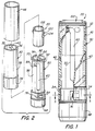
- FIG. 1 is a perspective view with a partial cutaway of an embodiment of a cosmetic dispenser with long lasting friction tab effect in accordance with the invention.
- FIG. 2 is an exploded view of the dispenser of FIG. 1.
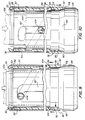
- FIG. 3 is a cross-sectional view along the line 3-3 of FIG. 1.
- FIG. 4 is a detail cross-sectional view of FIG. 3 showing a tab frictionally bearing against a cam sleeve base wall.
- FIG. 5 is a detail cross-sectional view of FIG. 3 showing a tab and cam sleeve base wall showing the wall after deflection of the relaxation zone which comprises a deformation section in the base wall.
- FIG. 6 is a detail cross-sectional side elevation view of the dispenser of FIG. 3 showing a tab frictionally bearing against a cam sleeve base wall.
- FIG. 7 is a detail cross-sectional view of an alternate embodiment of a dispenser in accordance with the invention showing a flex tab frictionally bearing against a cam sleeve base wall.
- FIG. 8 is a detail cross-sectional view of the embodiment of FIG. 7 showing a tab and cam sleeve base wall showing the tab seated in a relaxation notch.
- FIG. 9 is a cross-section elevation view of a bevelled shoulder of an innerbody engaging a cam sleeve in an embodiment of the invention.
- FIG. 10 is the view of FIG. 9 showing a locking effect when force is applied to the elevator cup.
- FIG. 11 is a detail cross-sectional elevation view of a lower edge of an inner wall of the cam sleeve abutting a shoulder of the innerbody in another embodiment of a dispenser in accordance with the invention.
- FIG. 12 is a detail cross-sectional elevation view of a lower edge of an inner wall of the cam sleeve abutting a shoulder of the innerbody in another embodiment of a dispenser in accordance with the invention.
- Referring now to FIGS. 1-12, where like elements are identified by like numbers in the drawings, an improved cosmetic dispenser with long lasting swivel drag and anti-back-off features is shown generally at 20.
Dispenser 20 comprises acam sleeve 30, aninnerbody 50, and anelevator cup 100. -
Cam sleeve 30 is rigid and tubular and has anupper end 32 and alower base 34.Cam sleeve 30 has an inner wall 36 and anouter wall 38. At least one and preferably two internalhelical tracks cam sleeve 30. Preferably, eachhelical track cam sleeve 30.Cam sleeve 30 has a smoothinner wall 44 at itsbase 34. An ornamentalouter shell 46 such as a brass tube may be fitted over theouter wall 38 of the cam sleeve for decoration. -
Innerbody 50 is also tubular and has anupper end 52 and alower end 54.Innerbody 50 has aninner wall 56 and anouter wall 58.Innerbody 50 is fitted into thecam sleeve 30 and has at least one and preferably twolongitudinal tracks innerbody 50 and which extend through thewalls innerbody 50 along a substantial length of theinnerbody 50. Preferably, one of thelongitudinal tracks 60 extends to theupper end 52 of theinnerbody 50 so that it is open at its upper end. The otherlongitudinal track 62 preferably does not so extend so that it is closed at its upper end. This permits easy assembly of theelevator cup 100 intoinnerbody 50. - The
longitudinal tracks lateral track segments longitudinal tracks lateral track segments elevator cup 100 to be locked in an extended position for application of a cosmetic. - The
innerbody 50 is interlocked with thecam sleeve 30 so that rotation or application of a swivel torque to thecam sleeve 30 relative to innerbody 50 can be accomplished by gripping an extendedcylindrical portion 68 oninnerbody 50 with one hand andcam sleeve 30 with the other hand to raise orlower elevator cup 100. Thecam sleeve 30 andinnerbody 50 are preferably secured together by a retaininglip 70 on theupper end 52 ofinnerbody 50 that retains theupper end 32 ofcam sleeve 30 in place oninnerbody 50. Theknob 68 ofinnerbody 50 has a larger diameter than thelower end 34 ofcam sleeve 30 and thereby holds the cam sleevelower end 34 in place. - The
elevator cup 100 is generally cylindrical and has achamber 102 for containing a cosmetic preparation such aslipstick pomade 108. Thecup 100 is fitted into theinnerbody 50.Cup 100 has at least one and preferably two cam follower lugs 104 for seating in and following in thelongitudinal tracks innerbody 50 and thehelical tracks cam sleeve 30. Thelugs 104 are located 180 degrees apart and have a sufficient length to extend through thelongitudinal tracks helical tracks Cup 100 is movable in an axial path in a conventional manner by relative rotation of theinnerbody 50 andcam sleeve 30 by virtue of thelugs 104 seating in thehelical tracks cam sleeve 30 and thelongitudinal tracks innerbody 50. The relative rotation of thecam sleeve 30 andinnerbody 50 causes thecup 100 to move axially to propel theelevator cup 100 to an extended position, and relative rotation in the opposite direction causes theelevator cup 100 to retract to a retracted position. In the preferred embodiment, thehelical tracks cam sleeve 30 and have a thread pitch of about 30 degrees so that each makes one complete revolution as thecup 100 traverses the length of thedispenser 20. This is desirable as only a single turn is needed to fully activate thedispenser 20 or to fully retract the dispenser. - A
resilient flex tab 76 is formed with and attached bytab root 77 to thelower end 54 of theinnerbody 50. Preferably there is asingle flex tab 76. Thetab 76 is at least partially cut away from theinnerbody 50 to enhance resilience. Theflex tab 76 may have various embodiments as described in the art, and has sufficient resilience to be flexed radially inwardly. - The
flex tab 76 provides a frictional braking effect against theinner wall 44 of thebase 34 ofcam sleeve 30, to give the desired drag and constant swivel torque. Because the frictional engagement takes place around a fixed annular wall in a circumferential path, an even drag is provided that is relatively insensitive to the position of the elevator cup along the innerbody. - The
inner wall 44 ofcam sleeve 30 is provided with arelaxation zone 80 so that thetab 76 has an opportunity to recall its original shape, so that thetab 76 will maintain a consistent frictional braking effect over time. In the absence ofsuch relaxation zone 80, thetab 76 can become ineffective over time as cold flow of the tab material causes thetab 76 to deform and lose its ability to frictionally press against thecam sleeve 30. Therelaxation zone 80 is located so that thetab 76 seats in therelaxation zone 80 when theelevator cup 100 ofdispenser 20 is retracted and/or when fully extended. Since the consumer will typically retract the cosmetic pomade after using thedispenser 20, and since thedispenser 20 is only in actual use a small percentage of the time, this provides sufficient time for thetab 76 to relax and obtain its original molded shape. In order to increase the likelihood that the consumer will fully retractelevator cup 100, the preferred embodiment ofdispenser 20 is a single turn dispenser where the consumer user can retract the elevator cup by one 360 degree turn ofcylindrical portion 68. - The
relaxation zone 80 may take several embodiments. One preferred embodiment comprises adeformable section 82 of the baseinner wall 44 which is made of a polymeric material. As shown in FIG. 5, thedeformable section 82 yields when atab 76 is pressed against thedeformable section 82, and thereby providestab 76 with an opportunity to regain its original shape. Such adeformable section 82 may be provided by manufacturing thebase 34 of thecam sleeve 30 withflat areas 84 on theouter wall 86 of thebase 34, so that the wall thickness of thebase 34 is reduced to weaken the wall ofbase 34 only in the deformable sections. This renders theinner wall 44 deformable in accordance with the invention. - Preferably there are two such
deformable sections 82 located 180 degrees apart. This permits thedispenser 20 to be assembled without insuring that asection 82 is aligned with thetab 76 on the innerbody. Instead, one of thesections 82 will automatically orient with thetab 76 when the components are assembled together to serve as therelaxation zone 80. By providing twodeformable sections 82 withflat areas 84 on theouter wall 86, theinner wall 44 remains circular so that a consistent swivel drag torque is provided on thedeformable section 82 that is not acting as therelaxation zone 80 fortab 76. In other words, the consumer will not notice any hesitations or variations in swivel torque when using thedispenser 20. Moreover, the integrity of thecam sleeve 30 is not compromised because thedeformation sections 82 are only a small portion of the total circumference of thebase 34. - As can be seen in FIGS. 4 and 5, the
tab 76 will seat in and cause deformation ofdeformation section 82 of just the amount necessary to permit relaxation oftab 76 such thattab 76 can regain its original molded shape. It is a characteristic of molded plastics that they will seek to recover their original molded shape when relieved of forces that cause deformation of the plastic. The present invention thus permits thetab 76 to recall its original shape and characteristics. - The
relaxation zone 80 is positioned on thecam sleeve 30 so that thetab 76 will seat in therelaxation zone 80 when theelevator cup 100 is fully retracted as well as when it is fully extended. The desired positioning of the components is achieved in the retracted position by placing thetab 76 directly beneath alongitudinal track innerbody 50, and locating thedeformable sections 82 on theinner wall 44 in alignment with the points of intersection in the assembled dispenser of thehelical tracks longitudinal tracks helical tracks lateral track segments deformable sections 82. This orientation is desirable because often a dispenser is delivered from a dispenser manufacturer to a cosmetic company with theelevator cup 100 in the extended position, as this may be required by the cosmetic company for filling the dispenser with a lipstick pomade. Since thedispenser 20 may be held in inventory prior to filling and sale in the extended position for indefinite periods, it is desirable that the relaxation effect be incorporated into the dispenser for when theelevator cup 100 is in the extended position. As prior discussed, the loadeddispenser 20 will normally be retracted after use by the consumer and the relaxation effect is therefore incorporated in the retracted position as well. - Another embodiment of the
relaxation zone 80 may comprise a relaxation notch 180 in theinner wall 44 of thecam sleeve 30, as shown in FIGS. 7 and 8, although this is a less desirable embodiment because it is necessary to aligncam sleeve 30 andinnerbody 50 when they are assembled together in order that thetab 76 will seat in notch 180 when the dispenser is retracted or extended. It is not desirable to use two such notches 180 because, unlike thedeformable sections 82 of the preferred embodiment, the notches 180 will provide an undesirable looseness and click upon rotation of thedispenser 20. - The present invention provides enhanced swivel drag and eliminates undesirable pomade back-off during use of the
dispenser 20 by providing abevelled shoulder 90 at the lower end ofinnerbody 50 that engages thelower edge 92 ofcam sleeve 30 as shown in FIGS. 9 and 10. - Referring to FIG. 9, the
tab 76 provides an outwardly directed force on one side of theinner wall 44 ofcam sleeve 30. This force pulls thecam sleeve 30 towards the side ofinnerbody 50 containingtab 76. This lateral force is translated, due to the angle ofbevelled shoulder 90, into upward motion and force aslower edge 92 rides upshoulder 90. Consequently, theupper edge 32 ofcam sleeve 30 is pressed against the retaininglip 70 ofinnerbody 50. This provides a substantial increase in swivel drag to impart the desired luxurious feel todispenser 20. This enhanced swivel drag also helps to reduce pomade back-off by resisting relative rotation of thecam sleeve 30 andinnerbody 50. Increased drag will also occur due to friction betweenbevelled shoulder 90 andlower edge 92. An additional benefit is that any unattractive gap that might exist between the retaininglip 70 and theupper edge 32 of thecam sleeve 30 is eliminated. - In addition, the
bevelled shoulder 90 will engagelower edge 92 and act as a positive frictional lock when force is applied topomade 108, as follows. Force, such as the pressure of a consumer's lips, is applied topomade 108, and will be transferred tolugs 104 ofelevator cup 100.Lugs 104, being seated inhelical tracks cam sleeve 30.Cam sleeve 30 is thereby moved downwardly slightly untillower edge 92 is jammed against and engagesshoulder 90, effectively preventing rotation ofcam sleeve 30 relative to innerbody 50 when theinnerbody knob 68 is held stationary. -
Angle 93 of bevelledshoulder 90 is preferably in the range of about 6-20 degrees, and most preferably is 10 degrees. It has been found that the 10 degree angle provides the optimum frictional drag effect as well as an optimum locking effect. - A
stop shoulder 94 is provided oninnerbody 50 to receive astop wall 96 ofcam sleeve 30. Stopshoulder 94 and stopwall 96 are located to prevent an over-extension ofcam sleeve 30 on bevelledshoulder 90 which might cause splitting of thelower base 34 ofcam sleeve 30. - An alternative embodiment for minimizing undesirable pomade back-off during use of the
dispenser 20 is shown in FIGS. 11 and 12, wherein an interference fit is provided between abevelled shoulder 190 oninnerbody 50 and a joining wall ofcam sleeve 30.Bevelled shoulder 190 is located at a higher location withincam sleeve 30 than theshoulder 90 shown in FIGS. 9 and 10. In FIG. 11, the camsleeve joining wall 192 is a step or edged wall where an upper portion of thecam sleeve 30 joins thebase wall 44. In FIG. 12, the camsleeve joining wall 194 is bevelled to provide amating surface 196 to fit against thebevelled shoulder 190 ofinnerbody 50. The joiningwalls shoulder 190 when a downward force is applied to thecam sleeve 30 and/ormetal shell 46 via the pomade as described above. When the joiningwalls cam sleeve 30 andinnerbody 50 are restricted. This embodiment thus also reduces the ability of theelevator cup 100 to retract and consequently alleviates pomade back-off. - The
innerbody 50 and thecam sleeve 30 are preferably formed by molding from a thermoplastic such as styrene. Theflex tab 76 is molded as part of theinnerbody 50. - If desired, ornamental coverings and caps may be provided as are known in the art.
- The present invention therefore provides a new and useful cosmetic dispenser with a substantially longer lasting frictional swivel drag effect than has been known in prior art dispensers, which is obtained without creating undesirable side effects.
- It is to be appreciated that the foregoing is illustrative and not limiting of the invention, and that various changes and modifications to the preferred embodiments described above will be apparent to those skilled in the art. Such changes and modifications can be made without departing from the spirit and scope of the present invention, and it is therefore intended that such changes and modifications be covered by the following claims.
Claims (8)
- A cosmetic dispenser (20), comprising: a cam sleeve (30) having upper and lower ends and inner and outer walls and having an internal helical track (40,42) extending along a substantial length of the inner wall of said cam sleeve (30), said cam sleeve having a tubular cam sleeve base (34); an innerbody (50) having upper and lower ends, said innerbody (50) being fitted into said tubular cam sleeve (30) and being provided with a longitudinal track (60,62) extending through the wall of said innerbody (50) along a substantial length of said innerbody, said innerbody having a retaining lip (70) at its upper end to retain said cam sleeve thereto; and a generally cylindrical elevator cup (100) for containing a cosmetic preparation, fitted into said innerbody (50) and having a cam follower lug (104) extending through said longitudinal track (60,62) to engage said helical track (40,42), said elevator cup being movable in an axial path by relative rotation of said innerbody (50) and cam sleeve (30);
characterized by having a bevelled shoulder (90, 190) around a lower outer wall of said innerbody, said tubular cam sleeve base (34) having an edge (92, 190, 194) located against said shoulder (90, 190); and means for pressing radially outwardly against said cam sleeve base to cause said cam sleeve (30) to rise on said bevelled shoulder (90, 190) to provide a frictional engagement said retaining lip (70) of said innerbody (50) and said upper end of said cam sleeve (30). - A dispenser in accordance with claim 1, wherein said bevelled shoulder (90) is provided at a lower end of said innerbody (50) and said edge of said cam sleeve (30) is a lower edge (92) located at a lowermost end of said cam sleeve (30).
- A dispenser in accordance with claim 1, wherein said bevelled shoulder (190) is provided above a lower end of said innerbody (50) and said edge of said cam sleeve (30) is a cam sleeve joining wall (192, 194) located where an upper portion of said cam sleeve 30 joins a base wall (44).
- A dispenser in accordance with claim 3, wherein said cam sleeve joining wall (192) is a step edged wall.
- A dispenser in accordance with claim 3, wherein said cam sleeve joining wall (194) is a bevelled wall.
- A cosmetic dispenser in accordance with claim 1, 2, 3, 4 or 5, wherein said bevelled shoulder (90, 190) has an angle of between about 6 to about 20 degrees from an axis of said innerbody (50).
- A cosmetic dispenser in accordance with claim 1, 2, 3, 4, 5 or 6, wherein said bevelled shoulder (90, 190) has an angle of about 10 degrees from an axis of said innerbody.
- A cosmetic dispenser in accordance with claim 1, 2, 3, 4, 5, 6, or 7, in which said means for pressing radially outwardly comprises at least one resilient tab (76) formed with and attached to said lower end of said innerbody (50), said resilient tab (76) frictionally engaging and bearing against said base (34) of said cam sleeve (30).
Applications Claiming Priority (3)
| Application Number | Priority Date | Filing Date | Title |
|---|---|---|---|
| US08/049,952 US5324126A (en) | 1993-04-20 | 1993-04-20 | Cosmetic dispenser with long lasting swivel drag effect |
| US49952 | 1993-04-20 | ||
| EP93304939A EP0620988B1 (en) | 1993-04-20 | 1993-06-24 | Cosmetic dispenser with long lasting swivel drag effect |
Related Parent Applications (2)
| Application Number | Title | Priority Date | Filing Date |
|---|---|---|---|
| EP93304939A Division EP0620988B1 (en) | 1993-04-20 | 1993-06-24 | Cosmetic dispenser with long lasting swivel drag effect |
| EP93304939.7 Division | 1993-06-24 |
Publications (3)
| Publication Number | Publication Date |
|---|---|
| EP0691092A2 true EP0691092A2 (en) | 1996-01-10 |
| EP0691092A3 EP0691092A3 (en) | 1996-01-17 |
| EP0691092B1 EP0691092B1 (en) | 1998-10-07 |
Family
ID=21962637
Family Applications (3)
| Application Number | Title | Priority Date | Filing Date |
|---|---|---|---|
| EP93304939A Expired - Lifetime EP0620988B1 (en) | 1993-04-20 | 1993-06-24 | Cosmetic dispenser with long lasting swivel drag effect |
| EP95202773A Expired - Lifetime EP0691092B1 (en) | 1993-04-20 | 1993-06-24 | Cosmetic dispenser with long lasting swivel drag effect |
| EP95202772A Expired - Lifetime EP0691091B1 (en) | 1993-04-20 | 1993-06-24 | Cosmetic dispenser with long lasting swivel drag effect |
Family Applications Before (1)
| Application Number | Title | Priority Date | Filing Date |
|---|---|---|---|
| EP93304939A Expired - Lifetime EP0620988B1 (en) | 1993-04-20 | 1993-06-24 | Cosmetic dispenser with long lasting swivel drag effect |
Family Applications After (1)
| Application Number | Title | Priority Date | Filing Date |
|---|---|---|---|
| EP95202772A Expired - Lifetime EP0691091B1 (en) | 1993-04-20 | 1993-06-24 | Cosmetic dispenser with long lasting swivel drag effect |
Country Status (8)
| Country | Link |
|---|---|
| US (1) | US5324126A (en) |
| EP (3) | EP0620988B1 (en) |
| AT (3) | ATE172853T1 (en) |
| CA (1) | CA2099048C (en) |
| DE (3) | DE69321486T2 (en) |
| DK (3) | DK0691091T3 (en) |
| ES (3) | ES2123621T3 (en) |
| GR (1) | GR3030865T3 (en) |
Cited By (1)
| Publication number | Priority date | Publication date | Assignee | Title |
|---|---|---|---|---|
| FR3039757A1 (en) * | 2015-08-04 | 2017-02-10 | Albea Services | RECEPTACLE FOR A COSMETIC PRODUCT, IN PARTICULAR FOR A COSMETIC PRODUCT STICK |
Families Citing this family (28)
| Publication number | Priority date | Publication date | Assignee | Title |
|---|---|---|---|---|
| FR2713455B1 (en) * | 1993-12-14 | 1996-02-02 | Oreal | Device for applying a pasty product, in particular a cosmetic product such as lipstick. |
| FR2722668B3 (en) * | 1994-07-20 | 1996-06-28 | Reboul Smt | MECHANISM FOR COSMETIC STICK CASE AND CASES COMPRISING SUCH A MECHANISM |
| DE4432108C2 (en) * | 1994-09-09 | 2001-09-06 | Oekametall Oehlhorn Gmbh & Co | Lipstick device with braking device |
| CA2156647A1 (en) | 1994-10-26 | 1996-04-27 | Risdon/Ams (Usa), Inc. | Cosmetic dispenser with flex ring for swivel drag |
| US5649777A (en) * | 1994-11-08 | 1997-07-22 | Risdon Corporation | Cosmetic dispenser with locking cup replaceable cartridge |
| US5636930A (en) * | 1994-12-28 | 1997-06-10 | Risdon Corporation | Cosmetic dispenser with cam locking feature |
| US5842804A (en) * | 1996-03-28 | 1998-12-01 | Rexam Cosmetic Packaging, Inc. | Lipstick case with means for push-back prevention |
| US5842803A (en) * | 1996-09-24 | 1998-12-01 | Rexam Cosmetic Packaging, Inc. | Cosmetic container for braking and centering coaxial, tubular members |
| US5888003A (en) * | 1997-02-05 | 1999-03-30 | Pierpont; Robert L. | Cosmetic container having an inner sleeve for creating torque |
| US6035866A (en) * | 1998-09-03 | 2000-03-14 | Eyelematic Manufacturing Co., Inc. | Pomade stick applicator with resilient sealing features |
| US6450717B1 (en) | 1999-11-25 | 2002-09-17 | Ivoclar Ag. | Applicator and method of applying |
| US6200049B1 (en) | 2000-03-16 | 2001-03-13 | Plastic-Envases, C.A. | Cosmetic dispenser and method |
| US6412999B1 (en) | 2001-03-02 | 2002-07-02 | Rexam Cosmetic Packaging | Cosmetic container with push-back prevention feature |
| FR2823957B1 (en) * | 2001-04-27 | 2003-06-27 | Rexam Reboul | LIQUID RED MECHANISM OR BRAKE BRAKE ANALOG |
| US6623198B2 (en) | 2001-10-09 | 2003-09-23 | Crown Cork & Seal Company, Inc. | Dispenser for cosmetics containing sunscreen |
| FR2846533B1 (en) | 2002-10-30 | 2005-09-30 | Rexam Reboul | LIQUID RED MECHANISM OR RELIEF - BRAKE - LIKE MECHANISM OF THE INTERNAL SHEATH. |
| US8523013B2 (en) * | 2005-03-09 | 2013-09-03 | Randy D. Sines | Elevating lift dispenser and container for articles in a liquid bath |
| US9896260B2 (en) | 2005-03-09 | 2018-02-20 | Twist 'n Serve, LLC | Elevating lift dispenser and container |
| US7325991B2 (en) * | 2005-06-24 | 2008-02-05 | Holloway Thomas F | Cosmetic dispenser with frictional drag |
| US7500799B2 (en) * | 2005-06-24 | 2009-03-10 | Hcp Packaging Usa, Inc. | Cosmetic dispenser with frictional swivel action |
| DE102008010435B4 (en) | 2008-02-21 | 2010-07-29 | Tecan Trading Ag | Data acquisition procedure with a laser scanner device |
| WO2015027207A1 (en) | 2013-08-22 | 2015-02-26 | Hcp Packaging Usa, Inc. | Double-ended cosmetic dispenser |
| WO2015112911A1 (en) | 2014-01-24 | 2015-07-30 | Hcp Packaging Usa, Inc. | Cosmetic dispenser with frictional resistance |
| US9642439B2 (en) | 2014-02-14 | 2017-05-09 | Hcp Packaging Usa, Inc. | Cosmetic dispenser with crenelated wall for frictional resistance |
| US11382400B2 (en) | 2018-08-10 | 2022-07-12 | Go Products Co. | Material applicator |
| US11485567B2 (en) * | 2020-04-09 | 2022-11-01 | Shi Chia Lin Industry Co., Ltd. | Coaxial container for dispensing a tubular product |
| US11395535B2 (en) | 2020-09-24 | 2022-07-26 | Hcp Packaging Usa, Inc. | Keyed refillable cosmetic dispenser |
| US11882916B2 (en) | 2020-09-24 | 2024-01-30 | Hcp Packaging Usa, Inc. | Refillable cosmetic dispenser |
Citations (3)
| Publication number | Priority date | Publication date | Assignee | Title |
|---|---|---|---|---|
| US4750501A (en) | 1986-11-18 | 1988-06-14 | Risdon Corporation | Cosmetic applicator with even torque and improved locking |
| US5186560A (en) | 1992-02-05 | 1993-02-16 | Risdon Corporation | Innerbody flex tab cosmetic dispenser |
| US5186561A (en) | 1992-03-17 | 1993-02-16 | Risdon Corporation | Incremental feel cosmetic dispenser |
Family Cites Families (17)
| Publication number | Priority date | Publication date | Assignee | Title |
|---|---|---|---|---|
| US2545864A (en) * | 1949-05-26 | 1951-03-20 | Eyelet Specialty Co | Cosmetic container or the like |
| US2545849A (en) * | 1949-05-26 | 1951-03-20 | Eyelet Specialty Co | Cosmetic container or the like |
| FR1040240A (en) * | 1951-07-31 | 1953-10-13 | G Rolot Et H Lemasson Ets | Improvements to cosmetic cases and the like |
| US2840229A (en) * | 1955-06-30 | 1958-06-24 | Eyelet Specialty Co | Cosmetic container |
| US2840231A (en) * | 1955-08-16 | 1958-06-24 | Eyelet Specialty Co | Moisture proof propellent applicator |
| US2913103A (en) * | 1958-10-08 | 1959-11-17 | Eyelet Specialty Co | Refillable cosmetic container |
| NL275525A (en) * | 1961-12-26 | |||
| US3335853A (en) * | 1965-05-19 | 1967-08-15 | Int Silver Co | Cosmetic container |
| DE1457441A1 (en) * | 1965-11-23 | 1968-12-19 | Oekametall Oehlhorn & Kahn Ohg | Lipstick sleeve with plastic rotating mechanism |
| FR1501043A (en) * | 1966-09-22 | 1967-11-10 | Ejectoret Sa | pasty product stick case |
| FR1589255A (en) * | 1968-10-10 | 1970-03-23 | ||
| DE2053268A1 (en) * | 1970-10-30 | 1972-05-04 | Oekametall Oehlhorn & Kahn oHG, 8600 Bamberg | Lipstick case with plastic rotating mechanism |
| IT1045464B (en) * | 1972-03-14 | 1980-05-10 | Ejectoret Sa | IMPROVEMENTS OF STUCCI FOR RASTONICINI OF PASTOUS PRODUCTS |
| FR2574640B1 (en) * | 1984-12-18 | 1987-02-13 | Oreal | DEVICE FOR APPLYING A PASTY PRODUCT, IN PARTICULAR A COSMETIC PRODUCT SUCH AS LIPSTICK, AND TUBULAR ELEMENT FOR SUCH A DEVICE |
| GB2213467B (en) * | 1987-12-09 | 1991-11-20 | Noxell Corp | Case for lipstick and like products |
| DE3812777A1 (en) * | 1988-04-16 | 1989-10-26 | Schmidt & Niedermeier | Container for a stick refill of a cosmetic substance, in particular lipstick |
| FR2657238B1 (en) * | 1990-01-19 | 1992-04-03 | Reboul Smt | BRAKING DEVICE ROTATING BETWEEN TWO CONCENTRIC ORGANS AND LIPSTICK CASE OR THE LIKE COMPRISING SUCH A DEVICE. |
-
1993
- 1993-04-20 US US08/049,952 patent/US5324126A/en not_active Expired - Lifetime
- 1993-06-23 CA CA002099048A patent/CA2099048C/en not_active Expired - Fee Related
- 1993-06-24 ES ES93304939T patent/ES2123621T3/en not_active Expired - Lifetime
- 1993-06-24 DK DK95202772T patent/DK0691091T3/en active
- 1993-06-24 ES ES95202772T patent/ES2133660T3/en not_active Expired - Lifetime
- 1993-06-24 AT AT93304939T patent/ATE172853T1/en not_active IP Right Cessation
- 1993-06-24 DK DK95202773T patent/DK0691092T3/en active
- 1993-06-24 ES ES95202773T patent/ES2122439T3/en not_active Expired - Lifetime
- 1993-06-24 AT AT95202773T patent/ATE171851T1/en not_active IP Right Cessation
- 1993-06-24 DE DE69321486T patent/DE69321486T2/en not_active Expired - Fee Related
- 1993-06-24 AT AT95202772T patent/ATE180147T1/en not_active IP Right Cessation
- 1993-06-24 EP EP93304939A patent/EP0620988B1/en not_active Expired - Lifetime
- 1993-06-24 DK DK93304939T patent/DK0620988T3/en active
- 1993-06-24 DE DE69325038T patent/DE69325038T2/en not_active Expired - Fee Related
- 1993-06-24 DE DE69321942T patent/DE69321942T2/en not_active Expired - Fee Related
- 1993-06-24 EP EP95202773A patent/EP0691092B1/en not_active Expired - Lifetime
- 1993-06-24 EP EP95202772A patent/EP0691091B1/en not_active Expired - Lifetime
-
1999
- 1999-07-27 GR GR990401951T patent/GR3030865T3/en unknown
Patent Citations (3)
| Publication number | Priority date | Publication date | Assignee | Title |
|---|---|---|---|---|
| US4750501A (en) | 1986-11-18 | 1988-06-14 | Risdon Corporation | Cosmetic applicator with even torque and improved locking |
| US5186560A (en) | 1992-02-05 | 1993-02-16 | Risdon Corporation | Innerbody flex tab cosmetic dispenser |
| US5186561A (en) | 1992-03-17 | 1993-02-16 | Risdon Corporation | Incremental feel cosmetic dispenser |
Cited By (1)
| Publication number | Priority date | Publication date | Assignee | Title |
|---|---|---|---|---|
| FR3039757A1 (en) * | 2015-08-04 | 2017-02-10 | Albea Services | RECEPTACLE FOR A COSMETIC PRODUCT, IN PARTICULAR FOR A COSMETIC PRODUCT STICK |
Also Published As
| Publication number | Publication date |
|---|---|
| EP0691091A3 (en) | 1996-01-17 |
| ATE171851T1 (en) | 1998-10-15 |
| DE69321942T2 (en) | 1999-04-15 |
| ATE180147T1 (en) | 1999-06-15 |
| DK0691092T3 (en) | 1999-06-21 |
| DE69325038T2 (en) | 1999-12-23 |
| EP0691091A2 (en) | 1996-01-10 |
| DK0620988T3 (en) | 1999-07-19 |
| DE69325038D1 (en) | 1999-06-24 |
| EP0620988A1 (en) | 1994-10-26 |
| EP0620988B1 (en) | 1998-11-04 |
| ATE172853T1 (en) | 1998-11-15 |
| DE69321942D1 (en) | 1998-12-10 |
| ES2133660T3 (en) | 1999-09-16 |
| ES2123621T3 (en) | 1999-01-16 |
| EP0691091B1 (en) | 1999-05-19 |
| DE69321486D1 (en) | 1998-11-12 |
| DE69321486T2 (en) | 1999-04-15 |
| US5324126A (en) | 1994-06-28 |
| DK0691091T3 (en) | 1999-11-29 |
| GR3030865T3 (en) | 1999-11-30 |
| ES2122439T3 (en) | 1998-12-16 |
| EP0691092B1 (en) | 1998-10-07 |
| EP0691092A3 (en) | 1996-01-17 |
| CA2099048A1 (en) | 1994-10-21 |
| CA2099048C (en) | 1995-04-11 |
Similar Documents
| Publication | Publication Date | Title |
|---|---|---|
| EP0691092B1 (en) | Cosmetic dispenser with long lasting swivel drag effect | |
| CA2081634C (en) | Incremental feel cosmetic dispenser | |
| EP0554974B1 (en) | Innerbody flex tab cosmetic dispenser | |
| US5636930A (en) | Cosmetic dispenser with cam locking feature | |
| US6412999B1 (en) | Cosmetic container with push-back prevention feature | |
| US7500799B2 (en) | Cosmetic dispenser with frictional swivel action | |
| EP0711519B1 (en) | Cosmetic dispenser with locking cup replaceable cartridge | |
| US5102249A (en) | Lipstick dispenser for shaped pomades | |
| US7325991B2 (en) | Cosmetic dispenser with frictional drag | |
| US6200049B1 (en) | Cosmetic dispenser and method | |
| US5879093A (en) | Mechanism for feeding stick type cosmetic materials, container employing the same and cartridge employed therein | |
| US6623198B2 (en) | Dispenser for cosmetics containing sunscreen | |
| US6244770B1 (en) | Dispenser with pomade holding flexible tab | |
| US20050063766A1 (en) | Applicator pen | |
| JP3333730B2 (en) | Bar-shaped cosmetic material feeding container | |
| US7651288B2 (en) | Cosmetic applicator with axial advance and retraction control | |
| EP0709042A1 (en) | Cosmetic dispenser with flex ring for swivel drag | |
| JP2002262936A (en) | Feeding container for stick cosmetic | |
| US3806263A (en) | Lipstick containers | |
| WO2008096148A1 (en) | Dispensing container for lipstick and the like | |
| JPH046648Y2 (en) | ||
| JP2598285Y2 (en) | Stick-shaped cosmetic dispensing container | |
| JPS6310099Y2 (en) | ||
| JPH0535798Y2 (en) | ||
| JPH08352A (en) | Case for pressing out solid cosmetic of stick form |
Legal Events
| Date | Code | Title | Description |
|---|---|---|---|
| PUAI | Public reference made under article 153(3) epc to a published international application that has entered the european phase |
Free format text: ORIGINAL CODE: 0009012 |
|
| PUAL | Search report despatched |
Free format text: ORIGINAL CODE: 0009013 |
|
| 17P | Request for examination filed |
Effective date: 19951013 |
|
| AC | Divisional application: reference to earlier application |
Ref document number: 620988 Country of ref document: EP |
|
| AK | Designated contracting states |
Kind code of ref document: A2 Designated state(s): AT BE CH DE DK ES FR GB GR IE IT LI LU MC NL PT SE |
|
| AK | Designated contracting states |
Kind code of ref document: A3 Designated state(s): AT BE CH DE DK ES FR GB GR IE IT LI LU MC NL PT SE |
|
| 17Q | First examination report despatched |
Effective date: 19960619 |
|
| GRAG | Despatch of communication of intention to grant |
Free format text: ORIGINAL CODE: EPIDOS AGRA |
|
| GRAG | Despatch of communication of intention to grant |
Free format text: ORIGINAL CODE: EPIDOS AGRA |
|
| GRAG | Despatch of communication of intention to grant |
Free format text: ORIGINAL CODE: EPIDOS AGRA |
|
| GRAH | Despatch of communication of intention to grant a patent |
Free format text: ORIGINAL CODE: EPIDOS IGRA |
|
| GRAH | Despatch of communication of intention to grant a patent |
Free format text: ORIGINAL CODE: EPIDOS IGRA |
|
| GRAA | (expected) grant |
Free format text: ORIGINAL CODE: 0009210 |
|
| RAP1 | Party data changed (applicant data changed or rights of an application transferred) |
Owner name: RISDON/AMS (USA), INC. |
|
| AC | Divisional application: reference to earlier application |
Ref document number: 620988 Country of ref document: EP |
|
| AK | Designated contracting states |
Kind code of ref document: B1 Designated state(s): AT BE CH DE DK ES FR GB GR IE IT LI LU MC NL PT SE |
|
| REF | Corresponds to: |
Ref document number: 171851 Country of ref document: AT Date of ref document: 19981015 Kind code of ref document: T |
|
| REG | Reference to a national code |
Ref country code: CH Ref legal event code: EP |
|
| REF | Corresponds to: |
Ref document number: 69321486 Country of ref document: DE Date of ref document: 19981112 |
|
| REG | Reference to a national code |
Ref country code: CH Ref legal event code: NV Representative=s name: FIAMMENGHI-FIAMMENGHI |
|
| REG | Reference to a national code |
Ref country code: IE Ref legal event code: FG4D Ref country code: ES Ref legal event code: FG2A Ref document number: 2122439 Country of ref document: ES Kind code of ref document: T3 |
|
| ET | Fr: translation filed | ||
| REG | Reference to a national code |
Ref country code: PT Ref legal event code: SC4A Free format text: AVAILABILITY OF NATIONAL TRANSLATION Effective date: 19981130 |
|
| PGFP | Annual fee paid to national office [announced via postgrant information from national office to epo] |
Ref country code: DK Payment date: 19990511 Year of fee payment: 7 |
|
| PGFP | Annual fee paid to national office [announced via postgrant information from national office to epo] |
Ref country code: AT Payment date: 19990512 Year of fee payment: 7 |
|
| PGFP | Annual fee paid to national office [announced via postgrant information from national office to epo] |
Ref country code: SE Payment date: 19990517 Year of fee payment: 7 |
|
| PGFP | Annual fee paid to national office [announced via postgrant information from national office to epo] |
Ref country code: MC Payment date: 19990518 Year of fee payment: 7 |
|
| PGFP | Annual fee paid to national office [announced via postgrant information from national office to epo] |
Ref country code: CH Payment date: 19990519 Year of fee payment: 7 |
|
| PGFP | Annual fee paid to national office [announced via postgrant information from national office to epo] |
Ref country code: PT Payment date: 19990520 Year of fee payment: 7 |
|
| PGFP | Annual fee paid to national office [announced via postgrant information from national office to epo] |
Ref country code: IE Payment date: 19990525 Year of fee payment: 7 |
|
| PGFP | Annual fee paid to national office [announced via postgrant information from national office to epo] |
Ref country code: NL Payment date: 19990531 Year of fee payment: 7 |
|
| PGFP | Annual fee paid to national office [announced via postgrant information from national office to epo] |
Ref country code: BE Payment date: 19990607 Year of fee payment: 7 |
|
| PGFP | Annual fee paid to national office [announced via postgrant information from national office to epo] |
Ref country code: LU Payment date: 19990617 Year of fee payment: 7 |
|
| PGFP | Annual fee paid to national office [announced via postgrant information from national office to epo] |
Ref country code: GR Payment date: 19990621 Year of fee payment: 7 |
|
| REG | Reference to a national code |
Ref country code: DK Ref legal event code: T3 |
|
| PLBE | No opposition filed within time limit |
Free format text: ORIGINAL CODE: 0009261 |
|
| STAA | Information on the status of an ep patent application or granted ep patent |
Free format text: STATUS: NO OPPOSITION FILED WITHIN TIME LIMIT |
|
| 26N | No opposition filed | ||
| PG25 | Lapsed in a contracting state [announced via postgrant information from national office to epo] |
Ref country code: LU Free format text: LAPSE BECAUSE OF NON-PAYMENT OF DUE FEES Effective date: 20000624 Ref country code: IE Free format text: LAPSE BECAUSE OF NON-PAYMENT OF DUE FEES Effective date: 20000624 Ref country code: DK Free format text: LAPSE BECAUSE OF NON-PAYMENT OF DUE FEES Effective date: 20000624 Ref country code: AT Free format text: LAPSE BECAUSE OF NON-PAYMENT OF DUE FEES Effective date: 20000624 |
|
| PG25 | Lapsed in a contracting state [announced via postgrant information from national office to epo] |
Ref country code: SE Free format text: LAPSE BECAUSE OF NON-PAYMENT OF DUE FEES Effective date: 20000625 |
|
| PG25 | Lapsed in a contracting state [announced via postgrant information from national office to epo] |
Ref country code: MC Free format text: THE PATENT HAS BEEN ANNULLED BY A DECISION OF A NATIONAL AUTHORITY Effective date: 20000630 Ref country code: LI Free format text: LAPSE BECAUSE OF NON-PAYMENT OF DUE FEES Effective date: 20000630 Ref country code: GR Free format text: LAPSE BECAUSE OF NON-PAYMENT OF DUE FEES Effective date: 20000630 Ref country code: CH Free format text: LAPSE BECAUSE OF NON-PAYMENT OF DUE FEES Effective date: 20000630 Ref country code: BE Free format text: LAPSE BECAUSE OF NON-PAYMENT OF DUE FEES Effective date: 20000630 |
|
| BERE | Be: lapsed |
Owner name: RISDON/AMS (USA) INC. Effective date: 20000630 |
|
| PG25 | Lapsed in a contracting state [announced via postgrant information from national office to epo] |
Ref country code: PT Free format text: LAPSE BECAUSE OF NON-PAYMENT OF DUE FEES Effective date: 20001231 |
|
| PG25 | Lapsed in a contracting state [announced via postgrant information from national office to epo] |
Ref country code: NL Free format text: LAPSE BECAUSE OF NON-PAYMENT OF DUE FEES Effective date: 20010101 |
|
| REG | Reference to a national code |
Ref country code: CH Ref legal event code: PL |
|
| EUG | Se: european patent has lapsed |
Ref document number: 95202773.8 |
|
| REG | Reference to a national code |
Ref country code: DK Ref legal event code: EBP |
|
| NLV4 | Nl: lapsed or anulled due to non-payment of the annual fee |
Effective date: 20010101 |
|
| REG | Reference to a national code |
Ref country code: IE Ref legal event code: MM4A |
|
| REG | Reference to a national code |
Ref country code: PT Ref legal event code: MM4A Free format text: LAPSE DUE TO NON-PAYMENT OF FEES Effective date: 20001231 |
|
| REG | Reference to a national code |
Ref country code: GB Ref legal event code: IF02 |
|
| PGFP | Annual fee paid to national office [announced via postgrant information from national office to epo] |
Ref country code: ES Payment date: 20080505 Year of fee payment: 16 |
|
| PGFP | Annual fee paid to national office [announced via postgrant information from national office to epo] |
Ref country code: IT Payment date: 20080625 Year of fee payment: 16 |
|
| PGFP | Annual fee paid to national office [announced via postgrant information from national office to epo] |
Ref country code: DE Payment date: 20080630 Year of fee payment: 16 |
|
| PGFP | Annual fee paid to national office [announced via postgrant information from national office to epo] |
Ref country code: GB Payment date: 20080425 Year of fee payment: 16 |
|
| GBPC | Gb: european patent ceased through non-payment of renewal fee |
Effective date: 20090624 |
|
| REG | Reference to a national code |
Ref country code: FR Ref legal event code: ST Effective date: 20100226 |
|
| PG25 | Lapsed in a contracting state [announced via postgrant information from national office to epo] |
Ref country code: FR Free format text: LAPSE BECAUSE OF NON-PAYMENT OF DUE FEES Effective date: 20090630 |
|
| PGFP | Annual fee paid to national office [announced via postgrant information from national office to epo] |
Ref country code: FR Payment date: 20080418 Year of fee payment: 16 |
|
| PG25 | Lapsed in a contracting state [announced via postgrant information from national office to epo] |
Ref country code: GB Free format text: LAPSE BECAUSE OF NON-PAYMENT OF DUE FEES Effective date: 20090624 |
|
| PG25 | Lapsed in a contracting state [announced via postgrant information from national office to epo] |
Ref country code: DE Free format text: LAPSE BECAUSE OF NON-PAYMENT OF DUE FEES Effective date: 20100101 |
|
| REG | Reference to a national code |
Ref country code: ES Ref legal event code: FD2A Effective date: 20090625 |
|
| PG25 | Lapsed in a contracting state [announced via postgrant information from national office to epo] |
Ref country code: ES Free format text: LAPSE BECAUSE OF NON-PAYMENT OF DUE FEES Effective date: 20090625 |
|
| PG25 | Lapsed in a contracting state [announced via postgrant information from national office to epo] |
Ref country code: IT Free format text: LAPSE BECAUSE OF NON-PAYMENT OF DUE FEES Effective date: 20090624 |