EP0690635A2 - Method for software charging in communication systems with non-redundant distributed devices - Google Patents
Method for software charging in communication systems with non-redundant distributed devices Download PDFInfo
- Publication number
- EP0690635A2 EP0690635A2 EP95109561A EP95109561A EP0690635A2 EP 0690635 A2 EP0690635 A2 EP 0690635A2 EP 95109561 A EP95109561 A EP 95109561A EP 95109561 A EP95109561 A EP 95109561A EP 0690635 A2 EP0690635 A2 EP 0690635A2
- Authority
- EP
- European Patent Office
- Prior art keywords
- peripheral devices
- connections
- peripheral
- communication channels
- switching
- Prior art date
- Legal status (The legal status is an assumption and is not a legal conclusion. Google has not performed a legal analysis and makes no representation as to the accuracy of the status listed.)
- Granted
Links
Images


Classifications
-
- H—ELECTRICITY
- H04—ELECTRIC COMMUNICATION TECHNIQUE
- H04Q—SELECTING
- H04Q3/00—Selecting arrangements
- H04Q3/42—Circuit arrangements for indirect selecting controlled by common circuits, e.g. register controller, marker
- H04Q3/54—Circuit arrangements for indirect selecting controlled by common circuits, e.g. register controller, marker in which the logic circuitry controlling the exchange is centralised
- H04Q3/545—Circuit arrangements for indirect selecting controlled by common circuits, e.g. register controller, marker in which the logic circuitry controlling the exchange is centralised using a stored programme
- H04Q3/54541—Circuit arrangements for indirect selecting controlled by common circuits, e.g. register controller, marker in which the logic circuitry controlling the exchange is centralised using a stored programme using multi-processor systems
- H04Q3/54558—Redundancy, stand-by
-
- H—ELECTRICITY
- H04—ELECTRIC COMMUNICATION TECHNIQUE
- H04Q—SELECTING
- H04Q3/00—Selecting arrangements
- H04Q3/42—Circuit arrangements for indirect selecting controlled by common circuits, e.g. register controller, marker
- H04Q3/54—Circuit arrangements for indirect selecting controlled by common circuits, e.g. register controller, marker in which the logic circuitry controlling the exchange is centralised
- H04Q3/545—Circuit arrangements for indirect selecting controlled by common circuits, e.g. register controller, marker in which the logic circuitry controlling the exchange is centralised using a stored programme
- H04Q3/54508—Configuration, initialisation
- H04Q3/54516—Initialization, software or data downloading
-
- H—ELECTRICITY
- H04—ELECTRIC COMMUNICATION TECHNIQUE
- H04Q—SELECTING
- H04Q2213/00—Indexing scheme relating to selecting arrangements in general and for multiplex systems
- H04Q2213/13003—Constructional details of switching devices
-
- H—ELECTRICITY
- H04—ELECTRIC COMMUNICATION TECHNIQUE
- H04Q—SELECTING
- H04Q2213/00—Indexing scheme relating to selecting arrangements in general and for multiplex systems
- H04Q2213/1302—Relay switches
-
- H—ELECTRICITY
- H04—ELECTRIC COMMUNICATION TECHNIQUE
- H04Q—SELECTING
- H04Q2213/00—Indexing scheme relating to selecting arrangements in general and for multiplex systems
- H04Q2213/1304—Coordinate switches, crossbar, 4/2 with relays, coupling field
-
- H—ELECTRICITY
- H04—ELECTRIC COMMUNICATION TECHNIQUE
- H04Q—SELECTING
- H04Q2213/00—Indexing scheme relating to selecting arrangements in general and for multiplex systems
- H04Q2213/1305—Software aspects
-
- H—ELECTRICITY
- H04—ELECTRIC COMMUNICATION TECHNIQUE
- H04Q—SELECTING
- H04Q2213/00—Indexing scheme relating to selecting arrangements in general and for multiplex systems
- H04Q2213/13166—Fault prevention
-
- H—ELECTRICITY
- H04—ELECTRIC COMMUNICATION TECHNIQUE
- H04Q—SELECTING
- H04Q2213/00—Indexing scheme relating to selecting arrangements in general and for multiplex systems
- H04Q2213/13167—Redundant apparatus
-
- H—ELECTRICITY
- H04—ELECTRIC COMMUNICATION TECHNIQUE
- H04Q—SELECTING
- H04Q2213/00—Indexing scheme relating to selecting arrangements in general and for multiplex systems
- H04Q2213/13292—Time division multiplexing, TDM
Definitions
- the invention relates to a method according to the preamble of patent claim 1.
- a communication system generally has different system availability requirements than many other technical systems and systems, such as data processing systems.
- a communication system therefore generally consists of at least duplicated central devices, such as the switching matrix, the message distribution units and central control devices. All of these devices are software-controlled single or multi-processor systems.
- commissioning communication systems the entire system software must be loaded into both the central and peripheral devices.
- software loading may also be necessary as a result of error corrections or the introduction of new features and services in the communication system. In this case it is generally necessary to change large parts of the entire software.
- the software In order to meet the need for the availability of the communication system for all participants, the software must be changed during operation; temporary traffic restrictions may then have to be accepted, the unavailability of the system for individual participants or the inaccessibility of individual participants or destinations must be avoided at all costs. Due to the limited redundancy and the possibly unavoidable traffic restriction, the time available for the entire change of the software is limited to a few hours, as a rule the change is carried out at times with low traffic load (for example during the night). If the amount of data to be loaded and the loading rate are unfavorable, the peripheral devices cannot be loaded successively because of this such a procedure might take several days to load.
- the central control device loads half of the peripheral devices with program information (switching, operational and administrative programs) as well as with the data associated with the device (connection location, signaling, authorization, phone numbers and other individual characteristics of connecting lines and subscriber lines and the condition and configuration of the facility).
- the program and data volumes to be loaded into the periphery are very extensive and are growing rapidly with the trend towards ever more powerful communication systems.
- the peripheral devices to be loaded are connected via a double message distribution system to the central control device, which carries out the secure transmission of the store messages as well as the distribution of normal switching and operational messages.
- the loading times are primarily limited by the transmission rate of the message distribution system in the direction of the periphery, but also by the performance of the central control device for providing the charging information and the transmission power on the interface between the central control device and the message distribution system.
- the peripheral devices or a part of the peripheral devices are being loaded, the PCM links connected to the peripheral devices in question are not available in terms of switching technology. Especially this applies to the PCM30 routes of a local exchange, which are assigned V5.2 interfaces standardized by ETSI / ITU.
- the system split is then established, as a result of which the first of these communication systems with the remaining active peripheral devices ensures normal operation with approximately 50% traffic restriction; the remaining of these two communication systems created in this way are assigned precisely the peripheral devices which have been switched off.
- the latter is then loaded with the new software and the switching technology operation is again permitted by restarting the newly loaded peripheral devices.
- This enables parallel operation of both communication systems, one of the systems being controlled with the old software and the remaining system already being controlled with the new software.
- the system which is still controlled with the old software loaded with the new software according to the same procedure, i.e. after traffic has been triggered and the remaining connections have been triggered, as described above.
- such a procedure is still problematic for the V5.2 interface mentioned above.
- V5.2 communication channels Generally there are up to three V5.2 communication channels (CC) per PCM30 route of a V5.2 interface. These are transmission channels via which signaling data, packet data and internal control data are transmitted (PSTN signaling, ISDN signaling, ISDN D-channel packet data, and control information of the subscriber concentrator connected via the V5.2 interface (Access Network)). Further details regarding the V5.2 interface can be found in the draft prETS-300 347-1 (ETSI specification V5.2) and in the draft prETS-300 347-2 (ETSI specification V5.2-PICS). The definition of the V5.2 interface builds up and is essentially identical to the standard of the V5.1 interface.
- the V5.2 communication channels are not operated during the loading time of the software in the peripheral devices terminating their PCM30 systems and are therefore not available during this time.
- a general equivalent circuit of the V5.2 communication channels of the half of the peripheral devices to be loaded with the new software to the half of the peripheral devices remaining in operation is generally not possible for the duration of the charging process. On the one hand, this is due to the fact that, according to the ETSI / ITU standard, not enough communication channels can be set up as replacement channels.
- the subscribers assigned to different V5.2 communication channels can, as standard, only with considerable administrative effort in the subscriber access network (AN) and the local exchange (LE) the V5.2 communication channels still available remaining peripheral half in operation.
- German Patent P 43 19 877 a method for loading software for accelerated commissioning of peripheral devices in communication systems is known from German Patent P 43 19 877.
- the latter are designed redundantly, which is why this method cannot be applied to non-redundant peripheral devices.
- the invention is based on the object of specifying a method which can be used to introduce software into the non-redundant peripheral devices of a communication system in such a way that the availability of the system for the connected participants is ensured during the change of the software.
- a particular advantage of the invention is the redirection of the V5.2 communication channels while the new software is being loaded into one system half to the other half of the system that is still in operation. If the loading process into one half of the system has been completed, it goes into operation and all V5.2 communication channels are now directed to this half of the system. Now the new software can be loaded into the remaining half of the system. This ensures that all V5.2 communication channels are used during the loading process of one system half into the remaining half of the system and that all participants are guaranteed system availability. With this procedure, peripheral devices can be loaded with software without affecting the availability of the communication system for the connected subscribers including V5.2 subscribers.
- the number of peripheral devices is an even number. This has the advantage that it is possible to find a halving of the peripheral devices assigned to V5.2 interfaces, whereby each V5.2 interface is connected to approximately 50% of its PCM30 systems to one of the halves of peripheral devices thus created , with which a maximum traffic restriction of approx. 50% can be guaranteed.
- the establishment of a defined initial state takes place by thinning out the switching traffic by processing existing connections for the duration of their existence, while new connection requests are only processed over the remaining half of the system until the by a certain criterion defined initial state is reached.
- the specific criterion is the achievement of a predetermined time mark or, if appropriate, a threshold value.
- the communication channels are fed from one system half to the remaining system half via a switching matrix designed as a redundant pair of central devices. This has the advantage that the redirection can be carried out without great administrative effort and hardware expenditure.
- the communication channels are fed from the one system half to the remaining system half by at least one upstream cross-connect switching device (eg 64 kbit / s).
- upstream cross-connect switching device eg 64 kbit / s.
- the protocol termination capacities remain in an active state during the switched-off state of one or the remaining half of the system. This has the advantage that the information to be transmitted can be transferred as internal system messages between the peripheral devices assigned to the system halves.
- the cross communication between the system halves can take place via the resources of the message distribution units or via additional resources. This has the advantage that decentralization and, consequently, an increase in the transmission rate between the system halves is advantageously achieved.
- predetermined time slots or channel numbers of the switching matrix interface used which are known in both system halves, are used to switch the communication channels. This has the advantage that cross communication to agree this data between the system halves can advantageously be omitted.
- the method can also be used if, due to the architecture of the system, the protocol termination capacities for the V 5.2-specific protocols are provided centrally and are not part of the peripheral devices.
- the method can be extended to the uninterrupted provision of access to packet networks for all connected packet participants.
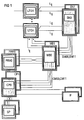
- FIG. 1 shows the typical system architecture of a communication system with unduplicated peripheral devices LTG1 ... LTGn. On the output side, they are connected to participants or other communication systems; the information originating from the last two are received by the peripheral devices LTG1 ... LTGn and fed to the redundant switching network SN0, SN1 via connections Lij. Furthermore, the peripheral devices LTG1 ... LTGn are connected via further connections Iij to the redundant message distribution units MB0, MB1, which in turn are connected via further connections Iij to the redundantly designed devices for handling central protocol completion tasks PRH (e.g. central drawing channel for No.
- PRH central protocol completion tasks
- the switching network SN0, SN1 and with the also redundant central control device CP0, CP1 are connected.
- the latter is connected to a double mass storage device SP.
- interface units IF are provided on the central control device CP0, CP1 for connecting operating elements or for alarming.
- the switching network SN0, SN1, the message distribution units MB0, MB1, the devices for handling central protocol completion tasks PRH0, PRH1, the central control device CP0, CP1 as well as the mass storage devices SP and the interface units IF are thus provided in duplicate in the communication system.
- the peripheral devices LTG1 ... LTGn are unduplicated in the present exemplary embodiment.
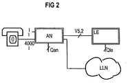
- the Access Network AN has a concentration function; with a subscriber concentration of 8: 1, for example, up to 4000 subscribers can be connected to a V5.2 interface of an Access Network AN with 16 PCM30 systems.
- the access network AN can have access to a leased line network LLN and can be connected via one or more V5.2 interfaces to communication systems with a local exchange function LE (Local Exchange).
- the communication system LE has an interface Qle and the access network AN has an interface Qan.
- the administration of the V5.2 interface and the associated participants is carried out functionally separately via the interfaces Qan, Qle via the Access Network AN and the communication system LE; administration is not (logically) via the V5.2 interface itself.
- Each V5.2 interface provides access to the LE communication system via 1 to 16 PCM30 connections.
- a maximum of three physical communication channels CC can be set up for each PCM30 connection in time slot 15, 16, 31.
- a time slot not used as a communication channel CC is available as a bearer channel, this applies in particular to time slot 16.
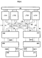
- FIG. 4 shows the relationships of the configuration according to FIG. 3 as the initial state before a software change.
- the Access Network AN is introduced to the peripheral devices LTG1 ... LTG4 via a V5.2 interface.
- peripheral connection device LTG1 ... LTG4 four PCM30 systems (see also Fig. 3) are used to connect a V5.2 Interface with a total of 16 PCM30 lines used.
- a switching network SN0, SN1, message distribution units MB0, MB1 and a central control device CP0, CP1 are shown as the central device of the communication system, all the latter devices being duplicated for security reasons.
- the peripheral device LTG3 terminates the PCM30 system (primary link) leading the active BCC / CTR C-channel of the V5.2 interface, which is why the function of the V5.2 master is assigned to it via the database. This means that it maintains all current states of the V5.2 interface.
- the assignments of the voice channels are stored here.
- the assignment of the Access Network participants to the voice channels is also carried out here.
- the peripheral device LTG2 terminates the PCM30 system (secondary link), which brings the standby BCC / CTR C-channel of the V5.2 interface, which is why all data of the master function are kept in sufficient redundancy for reasons of failure.
- the subscriber's signaling information is transmitted in a dedicated communication channel CC to one of the peripheral devices LTG1 ... LTG4. This can be the peripheral device LTG1, for example. It is then - due to the connection of this subscriber - responsible for signaling the subscriber.
- the peripheral device with master function LTG3 now uses a connection to assign the peripheral device LTG1 responsible for signaling to a peripheral device entrusted with carrying out switching tasks.
- This can be, for example, the LTG4 peripheral device. It is then responsible for the one-off connection or disconnection of this connection.
- the signaling information of the abovementioned subscriber brought in via the V5.2 communication channel are fed to the protocol termination capacity of the peripheral device LTG1 and subjected to an evaluation there.
- a transformation of the signaling information into a system-internal message is carried out here, which is then fed to the peripheral device LTG4 in the following, for example, via the message distribution unit MB0.
- the control of the peripheral device LTG is integrated in the signaling path.
- the peripheral device LTG1 is connected to the switching network half SN0 via connections L10 and to the redundant switching network half SN1 via connection L11. There are also connections I10 between the peripheral device LTG1 and the message distribution unit MB0 and connections I11 to the message distribution unit MB1.
- the other peripheral devices are connected to the central devices of the communication system in the same way:
- the peripheral device LTG2 is connected to the switching network half SN0 via connections L20 and to the switching network half SN1 via connections L21, while connections I20 to the message distribution unit MB0 and connections I21 to the message distribution unit MB1 also exist.
- the switching network SN0, the message distribution unit MB0, the central protocol termination device PRH0 and the central control device CP0 define the system half 0 below, which, as just shown - for the purpose of changing the software, the peripheral devices LTG1, LTG2 are assigned.
- the peripheral devices LTG3, LTG4 are connected to the central devices.
- the former is connected to the switching network half SN0 or the redundant switching network half SN1 via connecting lines L30, L31.
- Connections I30, I31 also exist to the message distribution unit MB0 or to the message distribution unit MB1, which is designed redundantly for this purpose.
- the peripheral device LTG4 is connected via connections L40, L41 to the switching matrix half SN0 or the redundantly designed switching matrix half SN1 and via connections I40, I41 to the message distribution unit MB0 or the redundant message distribution unit MB1.
- the switching network half SN1, the message distribution unit MB1, the central protocol termination device PRH1 and the central control device CP1 define the system half 1 below, which - as also shown - the peripheral devices LTG3, LTG4 are assigned for the purpose of changing the software. Furthermore, the switching network half SN0 is connected to the message distribution unit MB0 via connections SM00 in the same way as the switching network half SN1 is connected to the message distribution unit MB1 via connections SM11.
- the message distribution units MB0, MB1 are in turn connected to the central control device CP0, CP1 via connections CM00 and CM11, as shown in FIG. At the same time, there is a crossover between the message distribution units MB0, MB1 and the central control device CP0, CP1 via connections CM10, CM01.
- Fig. 4 shows a configuration as it appears immediately before the software change.
- approximately 50% of the traffic and, if the signaling is distributed uniformly over the peripheral devices LTG approximately 50% of the signaling is handled via the peripheral half 0.
- about 50% of the traffic and 50% of the signaling are handled via the peripheral half 1.
- the redundant normal operating mode of the communication system prevails, which means that both are generally Switching network halves SN0, SN1 must be switched through for each connection, the devices MB0, MB1, PRH0, PRH1 as well as CP0 and CP1 operate in their redundant mode, for example active / stand by or load sharing.
- the peripheral devices belonging to the system half that is to say the peripheral devices LTG1, LTG2, should first be loaded with new software.
- the traffic conducted via the peripheral devices LTG1, LTG2 is first thinned out in the redundant normal operating mode. This means that although existing connections are still permitted and processed, new connections are no longer permitted via this peripheral half. After a certain time, only a small part of the total traffic is then processed via the peripheral half 0, for example 3% of the traffic.
- the peripheral half 1 continues to provide approximately 50% of the traffic capacity of the normal operating state. The waiting time for traffic thinning can be set in advance if necessary.
- a further embodiment of the invention consists in allowing a threshold value, which is also defined in advance. Once this has been reached, the 'thinning out process' is also considered to be complete, which then creates a defined initial state in both cases. In a further embodiment of the invention, the thinning process to accelerate the method for changing the software can be omitted.
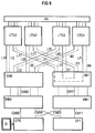
- the communication channels CC of peripheral half 0 are switched to peripheral half 1.
- Fig. 5 shows the relevant conditions.
- the communication channels CC arriving via the interface V5.2 are inserted in the peripheral devices LTG1, LTG2 in voice channels and then to the switching network half SN1 via the Transfer connections L11, L21.
- the relevant communication channels CC are switched to the peripheral devices LTG3, LTG4 via connections L41, L31.
- the communication channels are treated as if they were supplied via the connected V5.2 interface. If the voice channels on the connecting lines L11, L21, L31, L41 required for the through-connection are still used in terms of switching technology, the relevant connections are triggered before the communication channels CC are switched over.
- the switching-related residual traffic still handled by the peripheral half 0 is now triggered, the peripheral devices on the system side 0 are then switched off, and consequently no switching-related traffic is processed via this.
- the thinning out of the traffic in order to accelerate the method for changing the software can be omitted and the triggering can take place immediately.
- the traffic conducted via the peripheral devices on the system side 0 can also be triggered before the communication channels CC of the peripheral half 0 are switched to the peripheral half 1.
- the peripheral devices LTG1, LTG2 now have the inactive state, but the connection of the communication channels CC to the remaining system side 1 is retained. Furthermore, the old software is still loaded in the memories of the peripheral device LTG1, LTG2.
- the switching matrix half SN0, the message distribution unit MB0, the protocol termination unit PRH0 and the central control device CP0 are switched off.
- the crossover connections CM10, CM01 and the connections I11, I21 are thus activated.
- the associated protocol termination capacities are also inactive with the peripheral devices LTG1, LTG2. Therefore, the signaling information transmitted in the communication channels PC is not processed but only passed transparently to the switching network SN1.
- the central control device CP0 of the system half 0 is connected to an external storage medium SP, which can be configured as a floppy disk drive. Other storage media can optionally be used.
- the software to be loaded is removed from the floppy disk drive D and fed to the central control device CP0. From there, the transmission takes place via the connections CM00, SM00 and I10 or I20 into the memories of the peripheral devices LTG1, LTG2.
- the switching traffic is maintained with approx. 50% of the traffic capacity of the normal operating state.
- the loadable software parts of the devices PRH0, SN0, MB0 and in particular CP0 can advantageously also be loaded with a new associated software version.
- the redirection of the communication channels CC of system half 0 redirected via system half 1 is switched back again.
- system half 0 is again fully available for switching traffic, which means that an intermediate state is reached, which in principle corresponds to the defined initial state shown in FIG. 4, in that traffic can be handled 50% over both peripheral halves.
- system side 0 can only be active in terms of switching technology if there is a possibility of cross-communication between the system halves, which would give system half 0 access to the V5.2 interface controller, for example to assign voice channels to the V5.2 interface.
- the parallel operation of system half 0 with the new software version and system half 1 with the old software version is only possible if this cross communication option is available, which can be used advantageously for thinning out traffic via system half 1.
- System half 1 is then loaded with the new software.
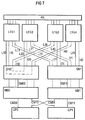
- the communication channels CC of system half 1 are switched to system half 0 - as shown in FIG. 7.
- the communication channels CC arriving via the interface V5.2 are inserted in the peripheral devices LTG3, LTG4 in voice channels and then transmitted to the switching network half SN0 via the connections L30, L40.
- the relevant communication channels CC are switched to the peripheral devices LTG1, LTG2 via connections L10, L20.
- the communication channels CC are treated as if they were supplied via the connected V5.2 interface.
- the central control device CP1 of the system half 1 is connected to an external storage medium SP, which can also be configured as a floppy disk drive D. Alternatively, other storage media can also be used here.
- the software to be loaded is removed from the floppy disk drive D and fed to the central control device CP1. From there, the software is transferred via the connections CM11, SM11 and I31 or I41 to the memories of the peripheral devices LTG3, LTG4.
- the switching traffic is maintained with approximately 50% of the traffic capacity of the normal operating state via system half 0.
- the loadable software parts of the devices PRH1, SN1, MB1 and in particular CP1 can advantageously also be loaded with a new software version.
- the central devices SN1, MB1, PRH1, CP1 which may also be supplied with new software, are switched off and the peripheral devices LTG3, LTG4 of system side 0 are switched on.
- System page 0 with the full periphery population LTG1 ... LTG4 hereby offers switching traffic via all V5.2 interfaces.
- the redirection of the communication channels CC of the peripheral half 1 redirected via the system half 0 is canceled again. This means that the entire system periphery is again fully available to switching traffic without switching the communication channels.
- redundant operation is restored by connecting the central components SN1, MB1, PRH1 and CP1.
- the software change has ended and the normal operating situation has been restored.
- connections can additionally be made between two, one system half each associated peripheral devices are provided. These can be connections between the peripheral devices LTG1, LTG4, for example.
- the communication channels CC can then be fed directly above it from, for example, the peripheral device LTG2 to the peripheral device LTG4.
- the communication channels CC can be redirected to an upstream cross-connect system based on 64 kbit / s channels.
- the protocol termination capacities are maintained in the active state.
- the information can then be transferred to other peripheral devices via other outputs.
- the V5.2-specific protocols can then be completed in the peripheral devices terminating the associated PCM30 routes, as a result of which the signaling and ISDN D-channel packet data introduced in the communication channels CC can be forwarded as system-internal messages to the half of the system that is still in operation.
- the message distribution unit that is still in operation or additional physical connections inserted between two peripheral devices of both peripheral halves can be used as the basis for the cross communication between the system halves instead of the central cross connection CM10, CM01.
- the time position or channel number which is used for switching through the communication channels CC, can be clearly known from the connection position and time slot number of the communication channels, so that cross-communication for transferring the time position or channel number between the system halves is omitted.
- the communication channels CC can also be routed to central protocol termination capacities, as can occur with greater flexibility in system architectures.
- the relationship of all ISDN packet subscribers to all packet networks accessible to them in normal operation can be maintained for the full duration of the software change, in particular for the duration of the non-redundant operation.
Abstract
Description
Die Erfindung betrifft ein Verfahren gemäß dem Oberbegriff des Patentanspruchs 1.The invention relates to a method according to the preamble of
Die effektive Bearbeitung und Steuerung anstehender Aufgaben wird in zeitgemäßen Kommunikationssystemen durch eine Dezentralisierung von Intelligenzleistung realisiert. Dies bedeutet, daß Programme, die in früheren programmgesteuerten Systemen in der zentralen Steuereinrichtung abgespeichert waren und dort zum Ablauf gelangt sind, einschließlich der zugehörigen Daten zur Peripherie hin verlagert sind und dort unabhängig von der zentralen Steuereinrichtung bearbeitet werden. Dies hat insbesondere den leistungssteigernden Vorteil, daß die zentrale Steuereinrichtung von der Steuerung peripherer Abläufe entlastet wird. Allerdings muß dann die betreffende periphere Software bei Inbetriebnahme des Kommunikationssystems zu jenen peripheren Einrichtungen hin übertragen und dort abgespeichert werden. Dieses Erfordernis besteht insbesondere bei einem Versionswechsel der Software aus Gründen der Fehlerbehebung oder des Einbringens neuer Leistungsmerkmale, gegebenenfalls ebenso nach einem Ausfall bzw. teilweisen Ausfall des Kommunikationssystems.The effective processing and control of pending tasks is realized in modern communication systems by decentralizing intelligence. This means that programs that were stored in previous program-controlled systems in the central control device and were executed there, including the associated data, have been moved to the periphery and are processed there independently of the central control device. This has in particular the performance-increasing advantage that the central control device is relieved of the control of peripheral processes. However, when the communication system is started up, the peripheral software in question must then be transmitted to those peripheral devices and stored there. This requirement exists in particular in the event of a change of version of the software for reasons of error correction or the introduction of new performance features, possibly also after a failure or partial failure of the communication system.
Da zeitgemäße Kommunikationssysteme ständig um neue Dienste und Leistungsmerkmale erweitert und somit auch die diese steuernden Programme und Daten häufig aktualisiert werden, kommt dem Wechsel der Software von Kommunikationssystemen eine immer größere Bedeutung zu. An ein Kommunikationssystem werden generell andere Anforderungen hinsichtlich der Systemverfügbarkeit gestellt als an viele andere technische Systeme und Anlagen wie beispsielsweise Datenverarbeitungsanlagen.Since modern communication systems are constantly being expanded to include new services and features, and thus the programs and data controlling them are frequently updated, the change in software of communication systems is becoming increasingly important. A communication system generally has different system availability requirements than many other technical systems and systems, such as data processing systems.
Insbesondere muß das Kommunikationssystem im Rahmen seiner Kapazitäten auch während des Einbringens einer neuen Software möglichst jederzeit für alle Teilnehmer verfügbar sein, eine Forderung, die indirekt über die Zuverlässigkeitsforderungen von ITU und BELLCORE an Kommunikationssysteme gestellt wird, aber auch direkt von den Betreibergesellschaften vorgebracht wird. Aus Zuverläsigkeitsgründen sind insbesondere die zentralen Einrichtungen des Kommunikationssystems redundant ausgeprägt. Daher besteht ein Kommunikationssystem in der Regel aus mindestens gedoppelten zentralen Einrichtungen, wie zum Beispsiel dem Koppelfeld, den Nachrichtenverteilereinheiten sowie zentralen Steuereinrichtungen. Alle diese Einrichtungen sind Softwaregesteuerte Ein- oder Mehrprozessorsysteme. Bei Inbetriebnahme von Kommunikationssystemen muß die gesamte Systemsoftware sowohl in die zentralen als auch in die peripheren Einrichtungen geladen werden. Das Laden von Software kann aber auch infolge von Fehlerkorrekturen oder der Einbringung neuer Leistungsmerkmale und Dienste in das Kommunikationssystem erforderlich werden. In diesem Fall ist dann im allgemeinen ein Wechsel großer Teile der gesamten Software unumgänglich.In particular, within the limits of its capacities, the communication system must be available to all participants at all times, even when introducing new software, a requirement that is made indirectly via the reliability requirements of ITU and BELLCORE for communication systems, but is also raised directly by the operating companies. For reasons of reliability, the central facilities of the communication system in particular are redundant. A communication system therefore generally consists of at least duplicated central devices, such as the switching matrix, the message distribution units and central control devices. All of these devices are software-controlled single or multi-processor systems. When commissioning communication systems, the entire system software must be loaded into both the central and peripheral devices. However, software loading may also be necessary as a result of error corrections or the introduction of new features and services in the communication system. In this case it is generally necessary to change large parts of the entire software.
Um dem Erfordernis der Verfügbarkeit des Kommunikationssystems für alle Teilnehmer gerecht zu werden, muß der Wechsel der Software während des laufenden Betriebs erfolgen; dabei müssen dann gegebenenfalls temporäre Verkehrseinschränkungen hingenommen werden, wobei die Nichtverfügbarkeit des Systems für einzelne Teilnehmer oder die Nichterreichbarkeit einzelner Teilnehmer oder Ziele unbedingt vermieden werden muß. Wegen der eingeschränkten Redundanz und der gegebenenfalls unumgänglichen Verkehrseinschränkung ist die für den gesamten Wechsel der Software zur Verfügung stehende Zeit auf wenige Stunden begrenzt, in der Regel wird der Wechsel in Zeiten mit geringer Verkehrslast (zum Beispiel während der Nachtstunden) durchgeführt. Bei ungünstigem Verhältnis von zu ladender Datenmenge und Laderate können aus diesem Grund die peripheren Einrichtungen nicht sukzessive geladen werden, da eine derartige Vorgehensweise unter Umständen mehrere Tage Ladezeit in Anspruch nehmen würde. Um dem Erfordernis des hinreichend schnellen Einbringens der Software gerecht zu werden, wird zum Beispiel jeweils eine Hälfte der peripheren Einrichtungen gleichzeitig geladen; die jeweils andere Hälfte der peripheren Einrichtungen erhält währenddessen den vermittlungstechnischen Betrieb aufrecht. Dies bedeutet in der Praxis eine ca. 50-%ige Verkehrseinschränkung, ein für verkehrsarme Zeiten duchaus tolerierbarer Wert. Beim Wechsel der Software der Kommunikationssysteme lädt die zentrale Steuereinrichtung dann jeweils eine Hälfte der peripheren Einrichtungen mit Programminformation (vermittlungstechnische, betriebstechnische und administrative Programme) sowie mit den der Einrichtung zugehörigen Dateninformationen (Anschlußlage, Signalisierung, Berechtigung, Rufnummern und weitere individuelle Charakteristika von Verbindungsleitungen und Teilnehmeranschlüssen sowie Ausbauzustand und Konfiguration der Einrichtung).In order to meet the need for the availability of the communication system for all participants, the software must be changed during operation; temporary traffic restrictions may then have to be accepted, the unavailability of the system for individual participants or the inaccessibility of individual participants or destinations must be avoided at all costs. Due to the limited redundancy and the possibly unavoidable traffic restriction, the time available for the entire change of the software is limited to a few hours, as a rule the change is carried out at times with low traffic load (for example during the night). If the amount of data to be loaded and the loading rate are unfavorable, the peripheral devices cannot be loaded successively because of this such a procedure might take several days to load. In order to meet the requirement of introducing the software sufficiently quickly, for example, half of the peripheral devices are loaded simultaneously; the other half of the peripheral facilities maintains the switching technology operation. In practice, this means an approx. 50% traffic restriction, a value that is tolerable for low-traffic times. When changing the software of the communication systems, the central control device then loads half of the peripheral devices with program information (switching, operational and administrative programs) as well as with the data associated with the device (connection location, signaling, authorization, phone numbers and other individual characteristics of connecting lines and subscriber lines and the condition and configuration of the facility).
Die in die Peripherie zu ladenden Programm- und Datenmengen sind sehr umfangreich und mit dem Trend zu immer leistungsfähigeren Kommunikationssystemen in starkem Wachstum begriffen. Die zu ladenden peripheren Einrichtungen sind dabei über ein gedoppeltes Nachrichtenverteilersystem mit der zentralen Steuereinrichtung verbunden, welche die gesicherte Übertragung der Ladenachrichten wie auch die Verteilung normaler vermittlungs- und betriebstechnischer Nachrichten vornimmt. Die Ladezeiten werden in erster Linie begrenzt durch die Übertragungsrate des Nachrichtenverteilersystems in Richtung Peripherie, ferner aber auch durch die Performance der zentralen Steuereinrichtung zur Bereitstellung der Ladeinformation und die Übertragungsleistung auf der Schnittstelle zwischen zentraler Steuereinrichtung und Nachrichtenverteilersystem. Während des Ladens der peripheren Einrichtungen oder eines Teils der peripheren Einrichtungen sind die an die betreffenden peripheren Einrichtungen angeschlossenen PCM-Strecken vermittlungstechnisch nicht verfügbar. Insbesondere gilt dies für die PCM30-Strecken eines Ortsvermittlungssystems, welche von ETSI/ITU standardisierte V5.2 Schnittstellen zugeordnet sind.The program and data volumes to be loaded into the periphery are very extensive and are growing rapidly with the trend towards ever more powerful communication systems. The peripheral devices to be loaded are connected via a double message distribution system to the central control device, which carries out the secure transmission of the store messages as well as the distribution of normal switching and operational messages. The loading times are primarily limited by the transmission rate of the message distribution system in the direction of the periphery, but also by the performance of the central control device for providing the charging information and the transmission power on the interface between the central control device and the message distribution system. While the peripheral devices or a part of the peripheral devices are being loaded, the PCM links connected to the peripheral devices in question are not available in terms of switching technology. Especially this applies to the PCM30 routes of a local exchange, which are assigned V5.2 interfaces standardized by ETSI / ITU.
Für Vermittlungsstellen ohne V5.2 Schnittstellen wurde dieses Problem bisher durch Etablierung eines sogenannten System Split gelöst:
Dies bedeutet die Aufhebung des Redundanzbetriebs aller zentralen Einrichtungen, wodurch zwei nicht redundante Komunikationssysteme entstehen. Zunächst wird dabei der über eine Peripheriehälfte abgewickelte vermittlungstechnische Verkehr ausgedünnt; dies bedeutet, daß Neubelegungen abgewiesen sowie die noch bestehenden Verbindungen abgewickelt werden. Nach einer gewissen Zeit wird dann nur noch ein geringer Teil des ursprünglich über diese Peripheriehälfte abgewickelten Verkehrs von derselben bearbeitet. Nun erfolgt ein Auslösen der noch bestehenden Verbindungen sowie ein Abschalten der der Peripheriehälfte zugehörigen peripheren Einrichtungen. Den beiden Peripheriehälften wird sodann je eine Hälfte der nicht mehr von jetzt an nicht mehr redundant arbeitenden zentralen Einrichtungen zugeordnet. Hierdurch entstehen zwei nicht redundante Kommunikationssysteme mit jeweils der Hälfte der nicht redundanten peripheren Einrichtungen. Damit ist dann der System Split etabliert, wodurch das erste dieser derart entstandenen Kommunikationssysteme mit den noch verbleibenden aktiven peripheren Einrichtungen einen normalen Betrieb mit ca. 50 % Verkehrseinschränkung gewährleistet; dem verbleibenden dieser derart entstandenen zwei Kommunikationssysteme sind genau die abgeschalteten peripheren Einrichtungen zugeordnet. Im folgenden wird dann letzteres mit der neuen Software geladen und der vermittlungstechnische Betrieb durch Wiederinbetriebnahme der nun neu geladenen peripheren Einrichtungen wieder zugelassen. Hiermit wird ein Parallelbetrieb beider Kommunikationssysteme erreicht, wobei eines der Systeme mit der alten Software und das verbleibende System bereits mit der neuen Software gesteuert wird. Im folgenden wird dann das System, das noch mit der alten Software gesteuert wird, nach der gleichen Vorgehensweise, also nach Verkehrsauslösung und Auslösen der Restverbindungen, mit der neuen Software geladen, wie oben geschildert. Eine derartige Vorgehensweise ist allerdings für die oben angesprochene V5.2 Schnittstelle immer noch problematisch. So ist die Methode des Systems Split nicht ohne weiteres auf derartige Schnittstellen anwendbar. Generell gibt es pro PCM30 Strecke einer V5.2 Schnittstelle bis zu drei sogenannte V5.2 Kommunikationskanäle (Communication Channels, CC). Dabei handelt es sich um Übertragungskanäle, über die Signalisierungsdaten, Paketdaten sowie interne Steuerdaten übertragen werden (PSTN Signalisierung, ISDN-Signalisierung, ISDN D-Kanal Paketdaten, sowie Steuerinformation des über die V5.2 Schnittstelle angeschlossenen Teilnehmerkonzentrators (Access Network)). Weitere Einzelheiten bezüglich der V5.2 Schnittstelle sind im Draft prETS-300 347-1 (ETSI Spezifikation V5.2) sowie im Draft prETS-300 347-2 (ETSI Spezifikation V5.2-PICS) aufgezeigt. Die Definition der V5.2 Schnittstelle baut auf und ist in wesentlichen Teilen identisch mit dem Standard der V5.1 Schnittstelle.For exchanges without V5.2 interfaces, this problem has so far been solved by establishing a so-called system split:
This means the redundancy operation of all central facilities is abolished, which creates two non-redundant communication systems. First of all, the switching traffic handled over a peripheral half is thinned out; this means that new assignments are rejected and the connections that are still in progress are processed. After a certain time, only a small part of the traffic originally processed via this peripheral half is then processed by the latter. Now the existing connections are triggered and the peripheral devices belonging to the peripheral half are switched off. One half of the central facilities which are no longer redundant from now on are then assigned to the two peripheral halves. This creates two non-redundant communication systems, each with half of the non-redundant peripheral devices. The system split is then established, as a result of which the first of these communication systems with the remaining active peripheral devices ensures normal operation with approximately 50% traffic restriction; the remaining of these two communication systems created in this way are assigned precisely the peripheral devices which have been switched off. In the following, the latter is then loaded with the new software and the switching technology operation is again permitted by restarting the newly loaded peripheral devices. This enables parallel operation of both communication systems, one of the systems being controlled with the old software and the remaining system already being controlled with the new software. In the following, the system which is still controlled with the old software, loaded with the new software according to the same procedure, i.e. after traffic has been triggered and the remaining connections have been triggered, as described above. However, such a procedure is still problematic for the V5.2 interface mentioned above. For example, the method of the split system is not readily applicable to such interfaces. Generally there are up to three V5.2 communication channels (CC) per PCM30 route of a V5.2 interface. These are transmission channels via which signaling data, packet data and internal control data are transmitted (PSTN signaling, ISDN signaling, ISDN D-channel packet data, and control information of the subscriber concentrator connected via the V5.2 interface (Access Network)). Further details regarding the V5.2 interface can be found in the draft prETS-300 347-1 (ETSI specification V5.2) and in the draft prETS-300 347-2 (ETSI specification V5.2-PICS). The definition of the V5.2 interface builds up and is essentially identical to the standard of the V5.1 interface.
Die V5.2 Kommunikationskanäle werden während der Ladezeit der Software in die ihre PCM30 Systeme terminierenden peripheren Einrichtungen nicht bedient und sind somit während dieser Zeit nicht verfügbar. Eine generelle, für die Dauer des Ladevorgangs vorgenommene Ersatzschaltung der V5.2 Kommunikationskanäle der mit der neuen Software zu ladenden Hälfte der peripheren Einrichtungen auf die im Betrieb verbleibende Hälfte der peripheren Einrichtungen ist im allgemeinen nicht möglich. Dies liegt zum einen daran, daß gemäß ETSI/ITU Standard nicht ausreichend viele Kommunikationskanäle als Ersatzkanäle einrichtbar sind. Zum andern können die, verschiedenen V5.2 Kommunikationskanälen zugeordneten Teilnehmer standardgemnäß nur mit erheblichen administrativen Aufwand im Teilnehmeranschlußnetz (AN) und der Ortsvermittlungsstelle (LE) den noch verfügbaren V5.2 Kommunikationskanälen der jeweils in Betrieb verbleibenden Peripheriehälfte zugeordnet werden.The V5.2 communication channels are not operated during the loading time of the software in the peripheral devices terminating their PCM30 systems and are therefore not available during this time. A general equivalent circuit of the V5.2 communication channels of the half of the peripheral devices to be loaded with the new software to the half of the peripheral devices remaining in operation is generally not possible for the duration of the charging process. On the one hand, this is due to the fact that, according to the ETSI / ITU standard, not enough communication channels can be set up as replacement channels. On the other hand, the subscribers assigned to different V5.2 communication channels can, as standard, only with considerable administrative effort in the subscriber access network (AN) and the local exchange (LE) the V5.2 communication channels still available remaining peripheral half in operation.
Als alternatives Verfahren zum Laden der neuen Software in die ungedoppelten peripheren Einrichtungen eines Kommunikationssystems ist das Laden von Programmen und Daten der neuen Software in einen insbesondere für den Zweck des Softwarewechsels bereitzustellenden Hintergrundspeicher der zu ladenden peripheren Einrichtungen zu nennen, wobei dieser im laufenden Betrieb unter der Steuerung der alten Software gefüllt wird. Ist dieser Hintergrundspeicher vollständig mit der neuen Softwareversion geladen, erfolgt die Aktivierung der neuen Software, der ein Kopieren der neuen Software in den Arbeitsspeicher vorausgehen kann. Nachteilig an dieser Vorgehensweise ist insbesondere die kurzfristige Nichtverfügbarkeit des gesamten Systems für die Dauer der Aktivierung der neuen Softwareversion. Bei kleinen peripheren Einrichtungen mit nur wenigen PCM Systemen aber relativ umfangreicher Softwareversionen tritt als weiterer, entscheidender Nachteil der Kostengesichtspunkt hervor, da mit diesem Verfahren der periphere Speicherbedarf und das periphere Speicherwachstum für zukünftige Softwaregenerationen verdoppelt wird. In der europäischen Patentanmeldung 93112277.4 ist eine derartige Vorgehensweise vorgeschlagen.As an alternative method for loading the new software into the unduplicated peripheral devices of a communication system, the loading of programs and data of the new software into a background memory of the peripheral devices to be loaded, which is to be made available in particular for the purpose of software change, is to be mentioned, whereby this is in operation under the Control of the old software is filled. If this background memory is completely loaded with the new software version, the new software is activated, which can be preceded by copying the new software into the main memory. A disadvantage of this procedure is in particular the short-term unavailability of the entire system for the duration of the activation of the new software version. In the case of small peripheral devices with only a few PCM systems but relatively large software versions, the cost aspect arises as a further, decisive disadvantage, since this method doubles the peripheral memory requirement and the peripheral memory growth for future software generations. Such a procedure is proposed in European patent application 93112277.4.
Weiterhin ist aus der deutschen Patentschrift P 43 19 877 ein Verfahren zum Laden von Software zur beschleunigten Inbetriebnahme von peripheren Einrichtungen in Kommunikationssystemen bekannt. Letztere sind allerdings redundant ausgestaltet, weswegen dieses Verfahren auf nichtredundante periphere Einrichtungen nicht anwendbar ist.Furthermore, a method for loading software for accelerated commissioning of peripheral devices in communication systems is known from German Patent P 43 19 877. However, the latter are designed redundantly, which is why this method cannot be applied to non-redundant peripheral devices.
Der Erfindung liegt die Aufgabe zugrunde, eine Methode anzugeben, die das Einbringen von Software in die nichtredundant ausgeprägten peripheren Einrichtungen eines Kommunikationssystems derart durchgeführt werden kann, daß die Verfügbarkeit des Systems für die daran angeschlossenen Teilnehmer während des Wechsels der Software sichergestellt ist.The invention is based on the object of specifying a method which can be used to introduce software into the non-redundant peripheral devices of a communication system in such a way that the availability of the system for the connected participants is ensured during the change of the software.
Die Erfindung wird, ausgehend vom Oberbegriff des Patentanspruchs 1 durch die Merkmale des kennzeichnenden Teils gelöst.Starting from the preamble of
Vorteilhaft an der Erfindung ist insbesondere das Umleiten der V5.2 Kommunikationskanäle während des Ladevorgangs der neuen Software in eine Systemhälfte auf die jeweils andere im Betrieb verbleibende Systemhälfte. Ist der Ladevorgang in die eine Systemhälfte abgeschlossen, so geht diese in Betrieb und alle V5.2 Kommunikationskanäle werden nun auf diese Systemhälfte geleitet. Nun kann die neue Software in die verbleibende Systemhälfte geladen werden. Damit ist sichergestellt, daß während des Ladevorgangs einer Systemhälfte in die jeweils verbleibende Systemhälfte alle V5.2 Kommunikationskanäle bedient und damit allen Teilnehmern die Systemverfügbarkeit gewährleistet ist. Mit dieser Vorgehensweise können periphere Einrichtungen mit Software geladen werden, ohne dabei die Verfügbarkeit des Kommunikationssystems für die angeschlossenen Teilnehmer an einschließlich der V5.2 Teilnehmer zu beeinträchtigen.A particular advantage of the invention is the redirection of the V5.2 communication channels while the new software is being loaded into one system half to the other half of the system that is still in operation. If the loading process into one half of the system has been completed, it goes into operation and all V5.2 communication channels are now directed to this half of the system. Now the new software can be loaded into the remaining half of the system. This ensures that all V5.2 communication channels are used during the loading process of one system half into the remaining half of the system and that all participants are guaranteed system availability. With this procedure, peripheral devices can be loaded with software without affecting the availability of the communication system for the connected subscribers including V5.2 subscribers.
Weitere Ausgestaltungen der Erfindung sind in den Unteransprüchen angegeben:
Gemäß Anspruch 2 ist vorgesehen, daß die Anzahl der peripheren Einrichtungen geradzahlig ist. Damit ist der Vorteil verbunden, daß es möglich ist, eine hälftige Aufteilung der V5.2 Schnittstellen zugeordneten peripheren Einrichtungen zu finden, wodurch jede V5.2 Schnittstelle jeweils mit ca. 50 % ihrer PCM30 Systeme an einer der so entstandenen Hälften peripherer Einrichtungen angeschlossen ist, womit eine maximale Verkehrseinschränkung von ca. 50 % garantiert werden kann.Further refinements of the invention are specified in the subclaims:
According to claim 2 it is provided that the number of peripheral devices is an even number. This has the advantage that it is possible to find a halving of the peripheral devices assigned to V5.2 interfaces, whereby each V5.2 interface is connected to approximately 50% of its PCM30 systems to one of the halves of peripheral devices thus created , with which a maximum traffic restriction of approx. 50% can be guaranteed.
Gemäß Anspruch 3 ist vorgesehen, daß das Herstellen eines definierten Anfangszustandes durch Ausdünnen des vermittlungstechnischen Verkehrs erfolgt, indem bestehende Verbindungen für die Dauer ihres Bestehens bearbeitet werden, während neue Verbindungswünsche nur noch über die im Betrieb verbleibende Systemhälfte bearbeitet werden, bis der durch ein bestimmtes Kriterium definierte Anfangszustand erreicht ist. Damit ist der Vorteil verbunden, daß ein darauffolgendes Auslösen der dann noch bestehenden Restverbindungen lediglich den Abbruch einiger, weniger Verbindungen bewirkt, womit ein Retten eines großen Teils aller stabilen Verbindungen i.a. erreicht werden kann.According to claim 3 it is provided that the establishment of a defined initial state takes place by thinning out the switching traffic by processing existing connections for the duration of their existence, while new connection requests are only processed over the remaining half of the system until the by a certain criterion defined initial state is reached. This has the advantage that a subsequent triggering of the remaining connections then only causes the termination of a few, fewer connections, with the result that a large part of all stable connections are generally saved. can be reached.
Gemäß Anspruch 4 ist vorgesehen, daß das bestimmte Kriterium das Erreichen einer vorgegebenen Zeitmarke oder gegebenenfalls eines Schwellenwertes ist. Damit ist der Vorteil verbunden, daß das Ende des Ausdünnungsprozesses durch zwei unabhängige Kriterien vorgebbar ist, welche den Grund des Rettens stabiler Verbindungen definieren.According to claim 4 it is provided that the specific criterion is the achievement of a predetermined time mark or, if appropriate, a threshold value. This has the advantage that the end of the thinning process can be specified by two independent criteria, which define the reason for the saving of stable connections.
Gemäß Anspruch 5 ist vorgesehen, daß im Falle des Unterbleibens des Informationsaustausches über Querverbindungen der definierte Zwischenzustand entfällt. Damit ist der Vorteil verbunden, daß im Falle keiner Kommunikationsmöglichkeit zwischen beiden Systemhälften zum einen keine unzulässigen Verkehrseinschränkungen und Teilnehmerausfälle entstehen und zum anderen das Verfahren beschleunigt wird.According to claim 5 it is provided that in the event of failure to exchange information via cross-connections the defined intermediate state is omitted. This has the advantage that, if there is no possibility of communication between the two halves of the system, on the one hand there are no impermissible traffic restrictions and subscriber failures and on the other hand the process is accelerated.
Gemäß Anspruch 6 ist vorgesehen, daß im Falle des Bestehens des Informationsaustausches über Querverbindungen der definierte Zwischenzustand durch Ausdünnen des vermittlungstechnischen Verkehrs über die zuletzt mit Software zu versorgende Systemhälfte erfolgt. Damit ist der Vorteil verbunden, daß im Falle einer Querkommunikationsmöglichkeit zwischen beiden Systemhälften das darauffolgende Auslösen der dann noch bestehenden Restverbindungen den Abbruch nur noch einiger, weniger Verbindungen bewirkt, womit ein Retten eines großen Teils aller stabilen Verbindungen i.a. erreicht werden kann.According to claim 6 it is provided that in the case of the existence of the exchange of information via cross-connections the defined intermediate state takes place by thinning out the switching traffic via the last system half to be supplied with software. This has the advantage that in the case of a cross-communication option between In both system halves, the subsequent triggering of the remaining connections then still causes the termination of only a few, fewer connections, with which a large part of all stable connections can generally be saved.
Gemäß Anspruch 7 ist vorgesehen, daß die bestehenden Verbindungen ohne vorheriges Ausdünnen des vermittlungstechnischen Verkehrs ausgelöst werden.Damit ist der Vorteil einer weiteren Beschleunigung des Verfahrens verbunden.According to claim 7 it is provided that the existing connections are released without prior thinning of the switching traffic. This is associated with the advantage of further accelerating the process.
Gemäß Anspruch 8 ist vorgesehen, daß das Zuführen der Kommunikationskanäle von der einen Systemhälfte zur verbleibenden Systemhälfte über ein, als redundant ausgebildetes Paar zentraler Einrichtungen ausgestaltetes Koppelfeld erfolgt. Damit ist der Vorteil verbunden, daß die Umleitung ohne großen administrativen Aufwand und Hardwareaufwand durchführbar ist.According to claim 8, it is provided that the communication channels are fed from one system half to the remaining system half via a switching matrix designed as a redundant pair of central devices. This has the advantage that the redirection can be carried out without great administrative effort and hardware expenditure.
Gemäß Anspruch 9 ist vorgesehen, daß im Falle des Bestehens einer zusätzlichen Verbindung zwischen jeweils zwei, verschiedenen Systemhälften zugeordneten peripheren Einrichtungen die Kommunikationskanäle direkt über diese zusätzlichen Verbindungen den betreffenden peripheren Einrichtungen zugeführt werden. Damit ist der Vorteil eines noch geringeren Zeitbedarfs verbunden.According to claim 9, it is provided that if there is an additional connection between two peripheral devices assigned to different system halves, the communication channels are fed directly to the relevant peripheral devices via these additional connections. This has the advantage of an even shorter time requirement.
Gemäß Anspruch 10 ist vorgesehen, daß das Zuführen der Kommunikationskanäle von der jeweils einen Systemhälfte zu der jeweils verbleibenden Systemhälfte durch wenigstens eine vorgeschaltete Cross-Connect Schaltvorrichtung (z.B. 64 kbit/s) erfolgt. Damit ist der Vorteil der Ausnutzung von unter Umständen sowieso vorhandenen vorgelagerten Einrichtungen des Kommunikationssystems verbunden, was zur weiteren Reduktion des Zeitbedarfs führt.According to claim 10 it is provided that the communication channels are fed from the one system half to the remaining system half by at least one upstream cross-connect switching device (eg 64 kbit / s). This is associated with the advantage of utilizing upstream devices of the communication system which may be present anyway, which leads to a further reduction in the time required.
Gemäß Anspruch 11 ist vorgesehen, daß für lokale Verbindungen zwischen zwei V5.2 Teilnehmern das Auslösen des vermittlungstechnischen Verkehrs entfällt. Damit ist der Vorteil verbunden, daß der Grad des Rettens stabiler Verbindungen über den Wechsel der Software hinaus weiter erhöht wird.According to claim 11 it is provided that for local connections between two V5.2 participants, the triggering of the switching traffic is eliminated. This has the advantage that the degree of rescue of stable connections is further increased beyond the change of the software.
Gemäß Anspruch 12 ist vorgesehen, daß die Protokollabschlußkapazitäten während des abgeschalteten Zustandes der einen bzw. verbleibenden Systemhälfte in einem aktiven Zustand verbleiben. Damit ist der Vorteil verbunden, daß die zu übertragenden Informationen als systeminterne Nachrichten zwischen den den Systemhälften zugeordneten peripheren Einrichtungen übergeben werden können.According to claim 12, it is provided that the protocol termination capacities remain in an active state during the switched-off state of one or the remaining half of the system. This has the advantage that the information to be transmitted can be transferred as internal system messages between the peripheral devices assigned to the system halves.
Gemäß Anspruch 13 ist vorgesehen, daß die Querkommunikation zwischen den Systemhälften über die Resourcen der Nachrichtenverteilereinheiten oder über zusätzliche Resourcen erfolgen kann. Damit ist der Vorteil verbunden, daß eine Dezentralisierung und damit einhergehend eine Erhöhung der Übertragungsrate zwischen den Systemhälften vorteilhaft erreicht wird.According to claim 13 it is provided that the cross communication between the system halves can take place via the resources of the message distribution units or via additional resources. This has the advantage that decentralization and, consequently, an increase in the transmission rate between the system halves is advantageously achieved.
Gemäß Anspruch 14 ist vorgesehen, daß zur Durchschaltung der Kommunikationskanäle vorbestimmte, in beiden Systemhälften bekannte Zeitlagen bzw. Kanalnummern der benutzten Koppelfeldschnittstelle benutzt werden. Damit ist der Vorteil verbunden, daß eine Querkommunikation zur Vereinbarung dieser Daten zwischen den Systemhälften vorteilhaft entfallen kann.According to claim 14, it is provided that predetermined time slots or channel numbers of the switching matrix interface used, which are known in both system halves, are used to switch the communication channels. This has the advantage that cross communication to agree this data between the system halves can advantageously be omitted.
Gemäß Anspruch 15 ist vorgesehen, daß das Verfahren auch dann Anwendung finden kann, wenn, durch die Architektur des Systems bedingt, die Protokollabschlußkapazitäten für die V 5.2 spezifischen Protokolle zentral vorgehalten werden und nicht Teil der peripheren Einrichtungen sind.According to claim 15, it is provided that the method can also be used if, due to the architecture of the system, the protocol termination capacities for the V 5.2-specific protocols are provided centrally and are not part of the peripheral devices.
Gemäß Anspruch 16 kann das Verfahren auf die ununterbrochene Bereitstellung des Zugangs zu Paketnetzen für alle angeschlossenen Paketteilnehmer erweitert werden.According to
Die Erfindung wird im folgenden anhand eines Ausführungsbeispiels näher erläutert.The invention is explained in more detail below using an exemplary embodiment.
Es zeigen
- Fig.1
- die typische Systemarchitektur eines Vermittlungssystems mit ungedoppelten peripheren Einrichtungen,
- Fig.2
- die Struktur des Access Network mit V5.2 Schnittstelle,
- Fig.3
- das Beispiel einer V5.2 Schnittstelle an einer Ortsvermittlungsstelle mit ungedoppelten peripheren Einrichtungen mit jeweils vier PCM30 Systemen,
- Fig.4 bis Fig.8
- das erfindungsgemäße Verfahren.
- Fig. 1
- the typical system architecture of a switching system with unduplicated peripheral devices,
- Fig. 2
- the structure of the Access Network with V5.2 interface,
- Fig. 3
- the example of a V5.2 interface at a local exchange with unduplicated peripheral devices, each with four PCM30 systems,
- Fig. 4 to Fig. 8
- the inventive method.
Fig.1 zeigt die typische Systemarchitektur eines Kommunikationssystems mit ungedoppelten peripheren Einrichtungen LTG1 ... LTGn. Sie sind ausgangsseitig mit Teilnehmern bzw. weiteren Kommunikationssystemen verbunden; die von den beiden letzten ausgehenden Informationen werden von den peripheren Einrichtungen LTG1 ... LTGn empfangen und über Verbindungen Lij dem redundant ausgebildeten Koppelfeld SN0, SN1 zugeführt. Weiterhin sind die peripheren Einrichtungen LTG1 ... LTGn über weitere Verbindungen Iij mit den redundant ausgebildeten Nachrichtenverteilereinheiten MB0, MB1 verbunden, die ihrerseits über weitere Verbindungen Iij zum einen mit den redundant ausgebildeten Einrichtungen zur Behandlung zentraler Protokollabschlußaufgaben PRH(z.B. zentraler Zeichenkanal für No. 7, Signalisierung, Zugang zu Paketnetzen) und zum anderen mit dem Koppelfeld SN0, SN1 sowie mit der ebenfalls redundant ausgebildeten zentralen Steuereinrichtung CP0, CP1 verbunden sind. Letztere ist an einen gedoppelten Massenspeicher SP angeschlossen. Im weiteren sind an die zentrale Steuereinrichtung CP0, CP1 Interface-Einheiten IF zur Anschaltung von Bedienungselementen bzw. zur Alarmierung vorgesehen. Das Koppelfeld SN0, SN1, die Nachrichtenverteilereinheiten MB0, MB1, die Einrichtungen zur Behandlung zentraler Protokollabschlußaufgaben PRH0, PRH1, die zentrale Steuereinrichtung CP0, CP1 sowie die Massenspeicher SP und die Interface-Einheiten IF sind somit im Kommunikationssystem jeweils gedoppelt vorgesehen. Die peripheren Einrichtungen LTG1 ... LTGn hingegen sind bei vorliegendem Ausführungsbeispiel ungedoppelt.1 shows the typical system architecture of a communication system with unduplicated peripheral devices LTG1 ... LTGn. On the output side, they are connected to participants or other communication systems; the information originating from the last two are received by the peripheral devices LTG1 ... LTGn and fed to the redundant switching network SN0, SN1 via connections Lij. Furthermore, the peripheral devices LTG1 ... LTGn are connected via further connections Iij to the redundant message distribution units MB0, MB1, which in turn are connected via further connections Iij to the redundantly designed devices for handling central protocol completion tasks PRH (e.g. central drawing channel for No. 7 , Signaling, access to packet networks) and on the other hand with the switching network SN0, SN1 and with the also redundant central control device CP0, CP1 are connected. The latter is connected to a double mass storage device SP. Furthermore, interface units IF are provided on the central control device CP0, CP1 for connecting operating elements or for alarming. The switching network SN0, SN1, the message distribution units MB0, MB1, the devices for handling central protocol completion tasks PRH0, PRH1, the central control device CP0, CP1 as well as the mass storage devices SP and the interface units IF are thus provided in duplicate in the communication system. The peripheral devices LTG1 ... LTGn, however, are unduplicated in the present exemplary embodiment.
Fig.2 zeigt eine typische Konfiguration, in der ein Access Network AN an eine Kommunikationssystem mit Ortsvermittlungsstellen-Funktion angeschaltet ist. Das Access Network AN weist dabei eine Konzentrationsfunktion auf; bei einer Teilnehmerkonzentration von 8:1 können beisspielsweise bis zu 4000 Teilnehmer an eine V5.2 Schnittstelle eines Access Network AN mit 16 PCM30-Systemen angeschlossen werden. Weiterhin kann das Access Network AN Zugang zu einem Leased Line Network LLN haben und über eine oder mehrere V5.2 Schnittstellen an Kommunikationssysteme mit Ortsvermittlungsstellen-Funktion LE (Local Exchange) angeschlossen sein. Das Kommunikationssystem LE weist eine Schnittstelle Qle sowie das Access Network AN eine Schnittstelle Qan auf. Die Administrierung der V5.2 Schnittstelle und der zugehörigen Teilnehmer erfolgt über die Schnittstellen Qan, Qle funktional getrennt über das Access Network AN sowie das Kommunikationssystem LE; die Administrierung erfolgt hierbei nicht (logisch) über die V5.2 Schnittstelle selbst hinweg. Jede V5.2 Schnittstelle bietet Zugang zum Kommunikationssystem LE über 1 bis 16 PCM30 Verbindungen. Dabei können je PCM30 Verbindung maximal drei physikalische Kommunikationskanäle CC eingerichtet werden, und zwar in Time Slot 15, 16, 31. Ein nicht als Kommunikationskanal CC genutzter Time Slot ist als Bearer Channel verfügbar, insbesondere gilt dies für Time Slot 16.2 shows a typical configuration in which an access network AN is connected to a communication system with a local exchange function. The Access Network AN has a concentration function; with a subscriber concentration of 8: 1, for example, up to 4000 subscribers can be connected to a V5.2 interface of an Access Network AN with 16 PCM30 systems. Furthermore, the access network AN can have access to a leased line network LLN and can be connected via one or more V5.2 interfaces to communication systems with a local exchange function LE (Local Exchange). The communication system LE has an interface Qle and the access network AN has an interface Qan. The administration of the V5.2 interface and the associated participants is carried out functionally separately via the interfaces Qan, Qle via the Access Network AN and the communication system LE; administration is not (logically) via the V5.2 interface itself. Each V5.2 interface provides access to the LE communication system via 1 to 16 PCM30 connections. A maximum of three physical communication channels CC can be set up for each PCM30 connection in
In Fig.3 sind diese Verhältnisse beispielhaft im Kommunikationssystem LE mit ungedoppelten peripheren Einrichtungen LTG1 ... LTG4 zu jeweils vier PCM30 Systemen detailliert aufgezeigt. Dabei sind an das Access Network AN analoge Teilnehmer und Nebenstellen (PSTN-Teilnehmer) sowie digitale Teilnehmer und Nebenstellen (Basic Access BA, Primary Rate Access PRA) angeschlossen. Das Access Network AN ist über jeweils vier PCM30 Systeme an die peripheren Anschlußeinrichtungen LTG1 ... LTG4 angeschlossen. Weiterhin bestehen Verbindungen der peripheren Anschlußeinrichtungen LTG1 ... LTG4 zum Koppelfeld SN0, SN1 sowie den Nachrichtenverteilereinheiten MB0, MB1. Das vermittlungstechnische und betriebstechnische Zusammenwirken der einzelnen Einrichtungen wird von der Steuereinrichtung CP0, CP1 bestimmt. Im Zeitschlitz 16 bestimmter PCM30 Systeme werden die V5.2 spezifischen Protokolle übertragen. Dabei sind beispielsweise zugeordnet:
- BCC/CTR
- C-Channel mit BCC, Control und Protection Protokoll
- PSTN
- C-Channel mit PSTN Protokoll
- ISDN-P
- C-Channel mit ISDN D-Kanal Paketdaten
- ISDN-DS
- C-Channel mit ISDN Signalisierungsdaten
- STB
- Stand-By C-Channel der Protection Group 2.
- BCC / CTR
- C-channel with BCC, control and protection protocol
- PSTN
- C-channel with PSTN protocol
- ISDN-P
- C-channel with ISDN D-channel packet data
- ISDN DS
- C-channel with ISDN signaling data
- STB
- Protection Group 2 stand-by C-Channel.
Im folgenden wird der Ablauf des erfindungsgemäßen Verfahrens detailliert beschrieben. Die entsprechenden Verfahrensschritte sind in den Figuren 4 bis 8 aufgezeigt. Fig. 4 zeigt die Verhältnisse der Konfiguration nach Fig.3 als Ausgangszustand vor einem Software-Wechsel. Darin ist das Access Network AN über eine V5.2 Schnittstelle an die peripheren Einrichtungen LTG1 ... LTG4 herangeführt. Dabei werden pro periphere Anschlußeinrichtung LTG1 ... LTG4 jeweils vier PCM30-Systeme (siehe auch Fig.3) für den Anschluß einer V5.2 Schnittstelle mit insgesamt 16 PCM30-Strecken verwendet. Weiterhin sind ein Koppelfeld SN0, SN1, Nachrichtenverteilereinheiten MB0, MB1 sowie eine zentrale Steuereinrichtung CP0, CP1 als zentrale Einrichtung des Kommunikationssystems aufgezeigt, wobei alle letztgenannten Einrichtungen aus Sicherheitsgründen gedoppelt sind. Die periphere Einrichtung LTG3 terminiert das den aktiven BCC/CTR C-Channel der V5.2 Schnittstelle heranführende PCM30 System (Primary Link), weshalb ihr über die Datenbasis die Funktion des V5.2-Masters zugewiesen ist. Dies bedeutet, daß sie alle aktuellen Zustände der V5.2 Schnittstelle führt.The sequence of the method according to the invention is described in detail below. The corresponding process steps are shown in FIGS. 4 to 8. FIG. 4 shows the relationships of the configuration according to FIG. 3 as the initial state before a software change. The Access Network AN is introduced to the peripheral devices LTG1 ... LTG4 via a V5.2 interface. For each peripheral connection device LTG1 ... LTG4 four PCM30 systems (see also Fig. 3) are used to connect a V5.2 Interface with a total of 16 PCM30 lines used. Furthermore, a switching network SN0, SN1, message distribution units MB0, MB1 and a central control device CP0, CP1 are shown as the central device of the communication system, all the latter devices being duplicated for security reasons. The peripheral device LTG3 terminates the PCM30 system (primary link) leading the active BCC / CTR C-channel of the V5.2 interface, which is why the function of the V5.2 master is assigned to it via the database. This means that it maintains all current states of the V5.2 interface.
Insbesondere sind hier die Belegungen der Sprachkanäle abgelegt. Die Zuordnung der Access Network Teilnehmer zu den Sprachkanälen wird hier ebenfalls durchgeführt. Die periphere Einrichtung LTG2 terminiert das den Stand-by BCC/CTR C-Channel der V5.2 Schnittstelle heranführende PCM30 System (Secondary Link), weshalb hier aus Ausfallgründen alle Daten der Master-Funktion in hinreichender Redundanz gehalten werden. Im Falle eines Verbindungsaufbaus, ausgehend von einem der V5.2 Schnittstellen Teilnehmer wird die Signalisierungsinformation des Teilnehmers in einem fest zugeordneten Kommunikationskanal CC einer der peripheren Einrichtungen LTG1 ... LTG4 übertragen. Dies kann zum Beispiel die periphere Einrichtung LTG1 sein. Sie ist dann - bedingt durch den Anschluß dieses Teilnehmers - für die Signalisierung des Teilnehmers verantwortlich. Die periphere Einrichtung mit Masterfunktion LTG3 nimmt nun auf Basis einer Verbindung eine Zuordnung der für die Signalisierung verantwortlichen peripheren Einrichtung LTG1 zu einer mit der Durchführung von Vermittlungsaufgaben betrauten peripheren Einrichtung vor. Dies kann zum Beispiel die periphere Einrichtung LTG4 sein. Sie ist dann für den einmaligen Auf- bzw. Abbau dieser Verbindung verantwortlich.In particular, the assignments of the voice channels are stored here. The assignment of the Access Network participants to the voice channels is also carried out here. The peripheral device LTG2 terminates the PCM30 system (secondary link), which brings the standby BCC / CTR C-channel of the V5.2 interface, which is why all data of the master function are kept in sufficient redundancy for reasons of failure. In the event of a connection being established, starting from one of the V5.2 interface subscribers, the subscriber's signaling information is transmitted in a dedicated communication channel CC to one of the peripheral devices LTG1 ... LTG4. This can be the peripheral device LTG1, for example. It is then - due to the connection of this subscriber - responsible for signaling the subscriber. The peripheral device with master function LTG3 now uses a connection to assign the peripheral device LTG1 responsible for signaling to a peripheral device entrusted with carrying out switching tasks. This can be, for example, the LTG4 peripheral device. It is then responsible for the one-off connection or disconnection of this connection.
Die über den V5.2 Kommunikationskanal herangeführte Signalisierungsinformation des vorstehend genannten Teilnehmers werden der Protokollabschlußkapazität der peripheren Einrichtung LTG1 zugeführt und dort einer Auswertung unterzogen. Insbesondere wird hier eine Transformation der Signalisierungsinformation in eine systeminterne Nachricht durchgeführt, die dann im folgenden beispielsweise über die Nachrichtenverteilereinheit MB0 der peripheren Einrichtung LTG4 zugeführt wird. Insbesondere ist bei dieser Vorgehensweise die Steuerung der peripheren Einrichtung LTG im Signalisierungsweg mit eingebunden. Dies hat zur Folge, daß im Falle des Ladens von Software in die periphere Einrichtung LTG diese generell - und besonders natürlich für die Weiterleitung der Signalisierungsinformation - nicht zur Verfügung steht.The signaling information of the abovementioned subscriber brought in via the V5.2 communication channel are fed to the protocol termination capacity of the peripheral device LTG1 and subjected to an evaluation there. In particular, a transformation of the signaling information into a system-internal message is carried out here, which is then fed to the peripheral device LTG4 in the following, for example, via the message distribution unit MB0. In particular, with this procedure the control of the peripheral device LTG is integrated in the signaling path. The consequence of this is that when software is loaded into the peripheral device LTG, it is generally not available - and particularly, of course, for the forwarding of the signaling information.
Weiterhin ist die periphere Einrichtung LTG1 über Verbindungen L10 an die Koppelfeldhälfte SN0 sowie über Verbindung L11 an die redundante Koppelfeldhäflte SN1 herangeführt. Ferner bestehen Verbindungen I10 zwischen der peripheren Einrichtung LTG1 und der Nachrichtenverteilereinheit MB0 und Verbindungen I11 zur Nachrichtenverteilereinheit MB1. In gleicher Weise sind auch die übrigen peripheren Einrichtungen an die zentralen Einrichtungen des Kommunikationssystsems angeschlossen:
So ist beispielsweise die periphere Einrichtung LTG2 über Verbindungen L20 mit der Koppelfeldhälfte SN0 sowie über Verbindungen L21 an die Koppelfeldhälfte SN1 angeschlossen, während zugleich Verbindungen I20 zur Nachrichtenverteilereinheit MB0 sowie Verbindungen I21 zur Nachrichtenverteilereinheit MB1 bestehen. Das Koppelfeld SN0, die Nachrichtenverteilereinheit MB0, die zentrale Protokollabschlußeinrichtung PRH0, sowie die zentrale Steuereinrichtung CP0 definieren im folgenden die Systemhälfte 0, der, wie soeben aufgezeigt - zum Zwecke des Wechsels der Software die peripheren Einrichtungen LTG1, LTG2 zugeordnet sind.Furthermore, the peripheral device LTG1 is connected to the switching network half SN0 via connections L10 and to the redundant switching network half SN1 via connection L11. There are also connections I10 between the peripheral device LTG1 and the message distribution unit MB0 and connections I11 to the message distribution unit MB1. The other peripheral devices are connected to the central devices of the communication system in the same way:
For example, the peripheral device LTG2 is connected to the switching network half SN0 via connections L20 and to the switching network half SN1 via connections L21, while connections I20 to the message distribution unit MB0 and connections I21 to the message distribution unit MB1 also exist. The switching network SN0, the message distribution unit MB0, the central protocol termination device PRH0 and the central control device CP0 define the system half 0 below, which, as just shown - for the purpose of changing the software, the peripheral devices LTG1, LTG2 are assigned.
In gleicher Weise sind die peripheren Einrichtungen LTG3, LTG4 an die zentralen Einrichtungen angeschlossen. Erstere ist über Verbindungsleitungen L30, L31 an die Koppelfeldhälfte SN0 bzw. die redundant ausgelegte Koppelfeldhälfte SN1 herangeführt. Weiterhin bestehen Verbindungen I30, I31 zu der Nachrichtenverteilereinheit MB0 bzw. der dazu redundant ausgelegten Nachrichtenverteilereinheit MB1. Die periphere Einrichtung LTG4 ist über Verbindungen L40, L41 an die Koppelfeldhälfte SN0 bzw. die redundant ausgelegte Koppelfeldhälfte SN1 angeschlossen sowie über Verbindungen I40, I41 an die Nachrichtenverteilereinheit MB0 bzw. die redundante Nachrichtenverteilereinheit MB1. Die Koppelfeldhälfte SN1, die Nachrichtenverteilereinheit MB1, die zentrale Protokollabschlußeinrichtung PRH1 sowie die zentrale Steuereinrichtung CP1 definieren im folgenden die Systemhälfte 1, der - wie ebenfalls aufgezeigt - zum Zwecke des Wechsels der Software die peripheren Einrichtungen LTG3, LTG4 zugeordnet sind. Weiterhin ist die Koppelfeldhälfte SN0 über Verbindungen SM00 mit der Nachrichtenverteilereinheit MB0 in gleicher Weise verbunden wie die Koppelfeldhälfte SN1 über Verbindungen SM11 mit der Nachrichtenverteilereinheit MB1. Die Nachrichtenverteilereinheiten MB0, MB1 sind ihrerseits wie in Fig.4 aufgezeigt mit der zentralen Steuereinrichtung CP0, CP1 über Verbindungen CM00 und CM11 verbunden. Gleichzeitig besteht eine Auskreuzung zwischen den Nachrichtenverteilereinheiten MB0, MB1 sowie der zentralen Steuereinrichtung CP0, CP1 über Verbindungen CM10, CM01.In the same way, the peripheral devices LTG3, LTG4 are connected to the central devices. The former is connected to the switching network half SN0 or the redundant switching network half SN1 via connecting lines L30, L31. Connections I30, I31 also exist to the message distribution unit MB0 or to the message distribution unit MB1, which is designed redundantly for this purpose. The peripheral device LTG4 is connected via connections L40, L41 to the switching matrix half SN0 or the redundantly designed switching matrix half SN1 and via connections I40, I41 to the message distribution unit MB0 or the redundant message distribution unit MB1. The switching network half SN1, the message distribution unit MB1, the central protocol termination device PRH1 and the central control device CP1 define the
Fig.4 zeigt eine Konfiguration, wie sie sich unmittelbar vor dem Software-Wechsel darstellt. In diesem Fall werden ca. 50 % des Verkehrs sowie bei gleichmäßiger Verteilung der Signalisierung auf die peripheren Einrichtungen LTG ca. 50 % der Signalisierung über die Peripheriehälfte 0 abgewickelt. Ebenso werden ca. 50 % des Verkehrs sowie 50 % der Signalisierung über die Peripheriehälfte 1 abgewickelt. Vor dem Wechsel der Software herrscht der redundante Normalbetriebsmodus des Kommunikationssystems, das heißt i.a. werden beide Koppelfeldhälften SN0, SN1 für jede Verbindung durchgeschaltet sein, die Einrichtungen MB0, MB1, PRH0, PRH1 sowie CP0 und CP1 arbeiten in ihrem redundanten Betrieb, zum Beispiel aktiv/stand by oder load sharing.Fig. 4 shows a configuration as it appears immediately before the software change. In this case, approximately 50% of the traffic and, if the signaling is distributed uniformly over the peripheral devices LTG, approximately 50% of the signaling is handled via the peripheral half 0. Likewise, about 50% of the traffic and 50% of the signaling are handled via the
Zunächst soll davon ausgegangen werden, daß keine Möglichkeit der Querkommunikation zwischen den beiden Systemhälften 0,1 gegeben ist. Weiterhin soll davon ausgegangen werden, daß zunächst die, der Systemhälfte 0 zugehörigen peripheren Einrichtungen also die peripheren Einrichtungen LTG1, LTG2 mit einer neuen Software geladen werden sollen. In diesem Fall wird zunächst im redundanten Normalbetriebsmodus der über die peripheren Einrichtungen LTG1, LTG2 geführte Verkehr ausgedünnt. Dies bedeutet, daß zwar bestehende Verbindungen noch zugelassen und bearbeitet werden, neue Verbindungen aber über diese Peripheriehälfte nicht mehr zugelassen werden. Nach einer gewissen Zeit wird dann über die Peripheriehälfte 0 nur noch ein geringer Teil des Gesamtverkehrs abgewickelt, zum Beispiel 3 % des Verkehrs. Die Peripheriehälfte 1 stellt weiterhin ca. 50 % der Verkehrskapazität des normalen Bestriebszustandes zur Verfügung. Die Wartezeit zur Verkehrsausdünnung kann gegebenenfalls vorab eingestellt werden. Eine weitere Ausgestaltung der Erfindung besteht darin, einen ebenfalls vorab definierten Schwellenwert zuzulassen. Ist dieser erreicht, gilt damit der 'Ausdünnugnsprozeß' ebenfalls als abgeschlossen, womit in beiden Fällen dann ein definierter Anfangszustand hergestellt ist. In einer weiteren Ausgestaltung der Erfindung kann der Ausdünnungsprozeß zur Beschleunigung des Verfahrens zum Wechsel der Software unterbleiben.First of all, it should be assumed that there is no possibility of cross-communication between the two system halves 0.1. Furthermore, it should be assumed that the peripheral devices belonging to the system half 0, that is to say the peripheral devices LTG1, LTG2, should first be loaded with new software. In this case, the traffic conducted via the peripheral devices LTG1, LTG2 is first thinned out in the redundant normal operating mode. This means that although existing connections are still permitted and processed, new connections are no longer permitted via this peripheral half. After a certain time, only a small part of the total traffic is then processed via the peripheral half 0, for example 3% of the traffic. The
Im folgenden werden die Kommunikationskanäle CC der Peripheriehälfte 0 auf die Peripheriehälfte 1 umgeschaltet. Die betreffenden Verhältnisse zeigt Fig.5. Dabei werden die über die Schntitstelle V5.2 ankommenden Kommunikationskanäle CC in den peripheren Einrichtungen LTG1, LTG2 in Sprachkanäle eingefügt und dann zur Koppelfeldhälfte SN1 hin über die Verbindungen L11, L21 übertragen. Dort werden die betreffenden Kommunikationskanäle CC zu den peripheren Einrichtungen LTG3, LTG4 über Verbindungen L41, L31 geschaltet. In den dort vorgesehenen Protokollabschlußeinrichtungen werden die Kommunikationskanäle damit so behandelt, als würden sie über die angeschlossenen V5.2 Schnittstelle zugeführt werden. Werden die für die Durchschaltung notwendigen Sprachkanäle auf den Verbindungsleitungen L11, L21, L31, L41 noch vermittlungstechnisch genutzt, so erfolgt ein Auslösen der betreffenden Verbindungen vor dem Umschalten der Kommunikationskanäle CC.In the following, the communication channels CC of peripheral half 0 are switched to
Der noch von der Peripheriehälfte 0 abgewickelte vermittlungstechnische Restverkehr wird nun ausgelöst, die peripheren Einrichtungen der Systemseite 0 werden dann abgeschaltet, demzufolge wird kein vermittlungstechnischer Verkehr hierüber mehr abgewickelt. In einer weiteren Ausgestaltung der Erfindung kann das Ausdünnen des Verkehrs zur Beschleunigung des Verfahrens zum Wechseln der Software unterbleiben und die Auslösung unmittelbar erfolgen. Ferner kann in einer weiteren Ausgestaltung der Erfindung das Auslösen des über die peripheren Einrichtungen der Systemseite 0 geführten Verkehrs auch vor dem Umschalten der Kommunikationskanäle CC der Peripheriehälfte 0 auf die Peripheriehälfte 1 erfolgen. Die peripheren Einrichtungen LTG1, LTG2 weisen nun den inaktiven Zustand auf, wobei die Durchschaltung der Kommunikationskanäle CC auf die verbleibende Systemseite 1 jedoch erhalten bleibt. Ferner ist die alte Software noch in den Speichern der peripheren Einrichtung LTG1, LTG2 geladen. Nun erfolgt die Abschaltung der Koppelfeldhälfte SN0, der Nachrichtenverteilereinheit MB0, der Protokollabschlußeinheit PRH0 und der zentralen Steuereinrichtung CP0. Damit sind die Auskreuzungsverbindungen CM10, CM01 sowie die Verbindungen I11, I21 aktiv geschaltet. Mit den peripheren Einrichtungen LTG1, LTG2 sind auch die zugehörigen Protokollabschlußkapazitäten inaktiv. Daher wird die in den Kommunikationskanälen PC übertragene Signalisierungsinformation nicht bearbeitet sondern lediglich transparent zum Koppelfeld SN1 durchgereicht.The switching-related residual traffic still handled by the peripheral half 0 is now triggered, the peripheral devices on the system side 0 are then switched off, and consequently no switching-related traffic is processed via this. In a further embodiment of the invention, the thinning out of the traffic in order to accelerate the method for changing the software can be omitted and the triggering can take place immediately. Furthermore, in a further embodiment of the invention, the traffic conducted via the peripheral devices on the system side 0 can also be triggered before the communication channels CC of the peripheral half 0 are switched to the
In diesem Konfigurationszustand kann neue Software in die peripheren Einrichtungen LTG1, LTG2 geladen werden. Die entsprechenden Verhältnisse sind in Fig.6 dargestellt. Zu diesem Zweck ist die zentrale Steuereinrichtung CP0 der Systemhälfte 0 an ein externes Speichermedium SP, das als Diskettenlaufwerk ausgestaltet sein kann, angeschlossen. Wahlweise können auch andere Speichermedien verwendet werden. Die zu ladende Software wird dem Diskettenlaufwerk D entnommen und der zentralen Steuereinrichtung CP0 zugeführt. Von dort erfolgt die übertragung über die Verbindungen CM00, SM00 sowie I10 bzw. I20 in die Speicher der peripheren Einrichtungen LTG1, LTG2. Während des Ladens der Software in die Systemhälfte 0 wird der vermittlungstechnische Verkehr mit ca. 50 % der Verkehrskapazität des normalen Betriebszustandes aufrecht erhalten. Dies erfolgt allerdings unter Verwendung der alten Software, die noch in den Speichern der peripheren Einrichtungen LTG3, LTG4 vorhanden ist. Vor bzw. im Rahmen des Ladens der peripheren Einrichtungen LTG1, LTG2 können die ladbaren Softwareanteile der Einrichtungen PRH0, SN0, MB0 und insbesondere CP0 vorteilhaft ebenfalls mit einem neuen zugehörigen Softwarestand geladen werden. Im folgenden wird nun die Umleitung der über die Systemhälfte 1 umgeleiteten Kommunikationskanäle CC der Systemhälfte 0 wieder zurückgeschaltet. Damit steht die Systemhälfte 0 prinzipiell für vermittlungstechnischen Verkehr wieder voll zur Verfügung, womit ein Zwischenzustand erreicht ist, der im Prinzip dem in Fig.4 aufgezeigten definierten Anfangszustand entspricht, indem der Verkehr über beide Peripheriehälften zu jeweils 50 % abgewickelt werden kann. Der wesentliche Unterschied zu der in Fig.4 aufgezeigten Konfiguration besteht darin, daß hier kein vermittlungstechnischer Verkehr über die Systemhälfte 0 abgewickelt werden kann, da die Masterfunktion der V 5.2 Schnittstelle sich nach wie vor auf der Systemseite 1 befindet. Mithin bilden die Systemseite 0 und die Systemseite 1 zwei konkurrierende Systeme, von denen die Systemseite 1 vermittlungstechnisch aktiv sein kann, da nur von hier aus die Steuerung des Access Network AN vorgenommen werden kann. Die Systemseite 0 kann in diesem Zustand nur dann zugleich vermittlungstechnisch aktiv sein, wenn eine Querkommunikationsmöglichkeit zwischen den Systemhälften vorhanden ist, womit die Systemhälfte 0 Zugriff auf die V5.2 Schnittstellensteuerung etwa zur Zuordnung von Sprachkanälen auf der V5.2 Schnittstelle hätte. Nur bei Vorhandensein dieser Querkommunikationsmöglichkeit ist der Parallelbetrieb von Systsemhälfte 0 mit der neuen Softwareversion und Systemhälfte 1 mit der alten Softwareversion möglich, welcher vorteilhaft für das Ausdünnen des Verkehrs über die Systemhälfte 1 genutzt werden kann. Falls keine Querkommunikationsmöglichkeit gegeben ist, entfällt dieser Zwischenzustand. Anschließend wird die Systemhälfte 1 mit der neuen Software geladen. Zu diesem Zweck werden die Kommunikationskanäle CC der Systemhälfte 1 auf die Systemhälfte 0 - wie in Fig. 7 aufgezeigt - umgeschaltet. Dabei werden die über die Schnittstelle V5.2 ankommenden Kommunikationskanäle CC in den peripheren Einrichtungen LTG3, LTG4 in Sprachkanäle eingefügt und dann zur Koppelfeldhälfte SN0 hin über die Verbindungen L30, L40 übertragen. Dort werden die betreffenden Kommunikationskanäle CC zu den peripheren Einrichtungen LTG1, LTG2 über Verbindungen L10, L20 geschaltet. In den dort vorgesehenen Protokollabschlußeinrichtungen werden die Kommunikationskanäle CC damit so behandelt, als würden sie über die angeschlossene V5.2 Schnittstelle zugeführt werden.In this configuration state, new software can be loaded into the peripheral devices LTG1, LTG2. The corresponding relationships are shown in Fig. 6. For this purpose, the central control device CP0 of the system half 0 is connected to an external storage medium SP, which can be configured as a floppy disk drive. Other storage media can optionally be used. The software to be loaded is removed from the floppy disk drive D and fed to the central control device CP0. From there, the transmission takes place via the connections CM00, SM00 and I10 or I20 into the memories of the peripheral devices LTG1, LTG2. During the loading of the software into system half 0, the switching traffic is maintained with approx. 50% of the traffic capacity of the normal operating state. However, this is done using the old software that is still available in the memories of the peripheral devices LTG3, LTG4. Before or during the loading of the peripheral devices LTG1, LTG2, the loadable software parts of the devices PRH0, SN0, MB0 and in particular CP0 can advantageously also be loaded with a new associated software version. In the following, the redirection of the communication channels CC of system half 0 redirected via
Die noch auf der Systemseite 1 bestehenden Verbindungen werden nun auf der Systemseite 1 ausgelöst. Da die Systemseite 1 mit dem Umschalten der Kommunikationskanäle auf die Systemseite 0 keinen Zugriff mehr auf die V5.2 Schnittstelle besitzt, erfolgt das Auslösen der über die Systemseite 1 geführten Verbindungen Access Network seitig unter der Steuerung der Systemseite 0. Diese existiert in Abhängigkeit von dem Vorhandensein einer Querkommunikationsmöglichkeit einer gezielten oder einer ungezielten Freigabe der zugehörigen Sprachkanäle. Die Systemseite 1 wird dann abgeschaltet, demzufolge wird kein vermittlungstechnischer Verkehr hierüber mehr abgewickelt. Die peripheren Einrichtungen LTG3, LTG4 weisen nun einen inaktiven Zustand auf, wobei die Durchschaltung der Kommunikationskanäle auf die verbleibende Systemseite jedoch erhalten bleibt. Ferner ist die alte Software noch in den Speichern der peripheren Einrichtungen LTG3, LTG4 geladen. Die Auskreuzungsverbindungen CM10, CM01 sowie die Verbindungen I40, I30 sind weiterhin inaktiv geschaltet. Mit den peripheren Einrichtungen LTG3, LTG4 sind auch die zugehörigen Protokollabschlußkapazitäten inaktiv. Daher wird die in den Kommunikationskanälen CC übertragene Signalisierungsinformation nicht bearbeitet, sondern lediglich transparent zum Koppelfeld SN0 durchgeschaltet.The connections still existing on
In diesem Konfigurationszustand kann neue Software in die peripheren Einrichtungen LTG3, LTG4 geladen werden. Die entsprechenden Verhältnisse sind in Fig.8 dargestellt. Zu diesem Zweck ist die zentrale Seuereinrichtung CP1 der Systemhälfte 1 an externes Speichermedium SP, das ebenfalls als Diskettenlaufwerk D ausgestaltet sein kann angeschlossen. Wahlweise können auch hier andere Speichermedien verwendet werden. Die zu ladende Software wird dem Diskettenlaufwerk D entnommen und der zentralen Steuereinrichtung CP1 zugeführt. Von dort erfolgt die Übertragung der Software über die Verbindungen CM11, SM11 sowie I31 bzw. I41 in die Speicher der peripheren Einrichtungen LTG3, LTG4. Während des Ladens der Software in die Systemhälfte 1 wird der vermittlungstechnische Verkehr mit ca. 50 % der Verkehrskapazität des normalen Betriebszustandes über die Systemhälfte 0 aufrechterhalten. Dies erfolgt bereits mit der neuen Software, die bereits in die Speicher der peripheren Einrichtungen LTG1, LTG2 geladen ist. Vor bzw. im Rahmen des Ladens der peripheren Einrichtungen LTG3, LTG4 können die ladbaren Softwareanteile der Einrichtungen PRH1, SN1, MB1 und insbesondere CP1 vorteilhaft ebenfalls mit einem neuen Softwarestand geladen werden.In this configuration state, new software can be loaded into the peripheral devices LTG3, LTG4. The corresponding relationships are shown in Fig. 8. For this purpose, the central control device CP1 of the
Im folgenden werden nun die zentralen, unter Umständen ebenfalls mit neuer Software versorgten zentralen Einrichtungen SN1, MB1, PRH1, CP1 abgeschaltet und die peripheren Einrichtungen LTG3, LTG4 der Systemseite 0 zugeschaltet. Hiermit bietet die Systemseite 0 mit der vollen Peripheriegesamtheit LTG1 ... LTG4 vermittlungstechnischen Verkehr über alle V5.2 Schnittstellen an. Sodann wird die Umleitung der über die Systemhälfte 0 umgeleiteten Kommunikationskanäle CC der Peripheriehälfte 1 wieder aufgehoben. Damit steht die gesamte Systemperipherie dem vermittlungstechnischen Verkehr ohne Umschalten der Kommunikationskanäle wieder voll zur Verfügung. Abschließend wird der redundante Betrieb durch Zuschalten der zentralen Komponenten SN1, MB1, PRH1 und CP1 wieder hergestellt. Das Ende des Wechsels der Software ist erreicht, die normale Betriebssituation ist wieder hergestellt.In the following, the central devices SN1, MB1, PRH1, CP1, which may also be supplied with new software, are switched off and the peripheral devices LTG3, LTG4 of system side 0 are switched on. System page 0 with the full periphery population LTG1 ... LTG4 hereby offers switching traffic via all V5.2 interfaces. Then the redirection of the communication channels CC of the
In einer weiteren Ausgestaltung der Erfindung wird davon ausgegangen, daß eine Querkommunikation zwischen den beiden Systemhälften 0 und 1 über die Auskreuzungsverbindungen CM10, CM01 erfolgt. In diesem Fall kann der vorstehend aufgezeigte Zwischenzustand dahingehend ausgestaltet werden, daß der Ausdünnungsprozeß auch auf die Systemseite 1 angewandt wird. Außerdem sind bei der Übergabe der, die aktuellen Kommunikationskanäle CC bestreffenden Konfigurationsdaten der mit der alten Software betriebenen Systemhälfte zu der Systemhälfte, die mit der neuen Software bestrieben wird, dann keinerlei Ersatzschaltungen von V5.2 Kommunikationskanälen auf der V5.2 Schnittstelle mehr nötig. In diesem Fall ist sogar ein Parallelbetrieb von alter und neuer Software möglich. Außerdem können stabile Verbindungen zwischen Teilnehmern, die über eine V5.2 Schnittstelle an der gleichen Ortsvermittlungsanlage angeschlossen sind, gerettet werden.In a further embodiment of the invention it is assumed that cross-communication takes place between the two
In einer weiteren Ausgestaltung der Erfindung können zusätzlich Verbindungen zwischen zwei, jeweils einer Systemhälfte zugeordneten peripheren Einrichtungen vorgesehen werden. Dies können beispielsweise Verbindungen zwischen den peripheren Einrichtungen LTG1, LTG4 sein. In diesem Fall können dann die Kommunikationskanäle CC direkt darüber von zum Beispiel der peripheren Einrichtung LTG2 der peripheren Einrichtung LTG4 zugeführt werden.In a further embodiment of the invention, connections can additionally be made between two, one system half each associated peripheral devices are provided. These can be connections between the peripheral devices LTG1, LTG4, for example. In this case, the communication channels CC can then be fed directly above it from, for example, the peripheral device LTG2 to the peripheral device LTG4.
Weiterhin kann das Umleiten der Kommunikationskanäle CC einem vorgeschalteten Cross-Connect-System auf Basis von 64 kBit/s Kanäle erfolgen.Furthermore, the communication channels CC can be redirected to an upstream cross-connect system based on 64 kbit / s channels.
In einer weiteren Ausgestaltung der Erfindung werden die Protokollabschlußkapazitäten im aktiven Zustand beibehalten. Damit können dann die Informationen über andere Ausgänge anderen peripheren Einrichtungen übergeben werden. Damit können dann die V5.2 spezifischen Protokolle in den die zugehörigen PCM30 Strecken terminierenden peripheren Einrichtungen abgeschlossen werden, wodurch die Weiterleitung der in den Komunikationskanälen CC herangeführten Signalisierung und ISDN D-Kanalpaketdaten als systeminterne Nachrichtenen an die jeweils in Betrieb verbleibende Systemhälfte erfolgen kann.In a further embodiment of the invention, the protocol termination capacities are maintained in the active state. The information can then be transferred to other peripheral devices via other outputs. The V5.2-specific protocols can then be completed in the peripheral devices terminating the associated PCM30 routes, as a result of which the signaling and ISDN D-channel packet data introduced in the communication channels CC can be forwarded as system-internal messages to the half of the system that is still in operation.
In einer weiteren Ausgestaltung der Erfindung kann als Basis der Querkommunikation zwischen den Systemhälften anstatt der zentralen Querverbindung CM10, CM01 die jeweils in Betrieb verbleibende Nachrichtenverteilereinheit oder zwischen jeweils zwei peripheren Einrichtungen beider Peripheriehälften zusätzlich eingefügte physikalische Verbindungen Verwendung finden.In a further embodiment of the invention, the message distribution unit that is still in operation or additional physical connections inserted between two peripheral devices of both peripheral halves can be used as the basis for the cross communication between the system halves instead of the central cross connection CM10, CM01.
In einer weiteren Ausgestaltung der Erfindung kann die Zeitlage bzw. Kanalnummer, welche zur Durchschaltung der Kommunikationskanäle CC verwendet wird, aus der Anschlußlage und Zeitschlitznummer der Kommunikationskanäle eindeutig bekannt werden, womit eine Querkommunikations zur Übergabe der Zeitlage bzw. Kanalnummer zwischen den Systemhälften entfällt.In a further embodiment of the invention, the time position or channel number, which is used for switching through the communication channels CC, can be clearly known from the connection position and time slot number of the communication channels, so that cross-communication for transferring the time position or channel number between the system halves is omitted.
In einer weiteren Ausgestaltung der Erfindung können die Kommunikationskanäle CC auch auf zentrale Protokollabschlußkapazitäten geführt sein, wie es in Systemarchitekturen mit größerer Flexibilität vorkommen kann.In a further embodiment of the invention, the communication channels CC can also be routed to central protocol termination capacities, as can occur with greater flexibility in system architectures.
In einer weiteren Ausgestaltung der Erfindung kann durch Anwendung des Verfahrens der Bezug aller ISDN-Paketteilnehmer zu allen ihm im normalen Betrieb zugänglichen Paketnetzen für die volle Dauer des Softwarewechsels insbesondere für die Dauer des nicht redundanten Betriebs erhalten werden.In a further embodiment of the invention, by using the method, the relationship of all ISDN packet subscribers to all packet networks accessible to them in normal operation can be maintained for the full duration of the software change, in particular for the duration of the non-redundant operation.
Claims (16)
dadurch gekennzeichnet,
daß nach Erreichen eines definierten Anfangszustandes in einem ersten Verfahrensschritt die über der einen Systemhälfte zugeordneten, peripheren Einrichtungen (LTG1 ... LTGm; LTGm+1 ... LTGn) geführten, in Kommunikationskanälen (CC) übertragenen Signalisierungs- und/oder Informationssignale in die Nachrichtenkanäle eingefügt und über erste der peripheren Verbindungen (Lij) der verbleibenden Systemhälfte zugeführt werden, wo sie zu wenigstens einer der verbleibenden Systemhälfte zugeordneten peripheren Einrichtung (LTGm+1 ... LTGn) über zweite der peripheren Verbindungen (Lij) weitergeleitet werden,
daß in einem zweiten Verfahrensschritt der noch von der einen Systemhälfte abgewickelte vermittlungstechnische Verkehr gegebenenfalls ausgelöst wird,
daß in einem dritten Verfahrensschritt die Software in die betreffende eine Systemhälfte und die dieser zugeordneten peripheren Einrichtungen (LTG1 ... LTGm) geladen wird, daß in einem vierten Verfahrensschritt das Zuführen der in Nachrichtenkanälen eingefügten, in Kommunikationskanäle (CC) übertragenen Signalisierungs- und/oder Informationssignale in die verbleibende Systemhälfte wieder rückgängig gemacht wird, womit ein definierter Zwischenzustand erreicht wird, und daß im Anschluß daran die Verfahrensschritte 1 bis 4 auf die verbleibende Systemhälfte sowie die dieser zugeordneten peripheren Einrichtungen (LTGm+1 ... LTGn) in gleicher Weise Anwendung finden wie zuvor auf die betreffende eine Systemhälfte sowie die dieser zugeordneten peripheren Einrichtungen (LTG1 ... LTGm), wobei der definierte Zwischenzustand entfällt, bis die Software entsprechend auch in die, der verbleibenden Systemhälfte zugeordnete peripheren Einrichtungen (LTGm+1 ... LTGn) geladen ist, und
daß abschließend der redundante Betrieb wieder hergestellt wird.Method for loading software into a communication system with at least two pairs of central, mutually assigned, redundantly configured devices (CP0, CP1; MB0, MB1; SN0, SN1; PRH0, PRH1), each of which has one system half (SN0, MB0, CP0, PRH0) as well as the redundant system half (SN1, MB1, CP1, PRH1) and which may exchange information via cross-connections (CM10, CM01) as well as with a plurality of peripheral devices (LTG1 ..) assigned to one or the remaining half of the system. . LTGn), which are connected to each of the central, redundantly designed devices (SN0, SN1; MB0, MB1) of at least one pair of central devices via peripheral connections (Lij, Iij), at least one of the peripheral devices (LTG1 .. . LTGn) is connected to a standardized interface, in particular a V5.2 interface, via which switching traffic in message channels and communication channels channels (CC) of the first or second system half,
characterized by
that after reaching a defined initial state in a first process step, the signaling and / or information signals transmitted in communication channels (CC) are routed over the peripheral devices assigned to one system half (LTG1 ... LTGm; LTGm + 1 ... LTGn) Message channels are inserted and fed via first of the peripheral connections (Lij) to the remaining half of the system, where they are forwarded to at least one peripheral device (LTGm + 1 ... LTGn) assigned to the remaining half of the system via second of the peripheral connections (Lij),
that in a second procedural step the switching traffic still handled by one half of the system may be triggered,
that in a third method step the software is loaded into the relevant system half and the peripheral devices assigned to it (LTG1 ... LTGm), that in a fourth method step the supply of the signaling and / or communication signals (CC) inserted in message channels and transmitted in communication channels (CC) is transmitted or information signals in the remaining half of the system is undone again, thus achieving a defined intermediate state, and that process steps 1 to 4 for the remaining half of the system and the peripheral devices (LTGm + 1 ... LTGn) assigned to it then follow in the same way As before, they are applied to the relevant system half and the peripheral devices assigned to it (LTG1 ... LTGm), the defined intermediate state being omitted until the software also correspondingly to the peripheral devices assigned to the remaining system half (LTGm + 1 ... LTGn) is loaded, and
that redundant operation is finally restored.
dadurch gekennzeichnet,
daß die Anzahl der peripheren Einrichtungen (n) geradzahlig ist.Method according to claim 1,
characterized by
that the number of peripheral devices (n) is an even number.
dadurch gekennzeichnet,
daß das Herstellen eines definierten Anfangszustandes durch Ausdünnen des vermittlungstechnischen Verkehrs erfolgt, indem bestehende Verbindungen für die Dauer ihres Bestehens bearbeitet werden, während neue Verbindungswünsche abgewiesen werden, bis der durch ein bestimmtes Kriterium definierte Anfangszustand erreicht ist.The method of claim 1 or 2,
characterized by
that the establishment of a defined initial state takes place by thinning out the switching traffic by processing existing connections for the duration of their existence, while new connection requests are rejected until the initial state defined by a certain criterion is reached.
dadurch gekennzeichnet,
daß das bestimmte Kriterium das Erreichen einer vorgegebenen Zeitmarke oder gegebenenfalls eines Schwellenwertes ist.Method according to claim 3,
characterized by
that the determined criterion is the achievement of a predetermined time mark or, if appropriate, a threshold value.
dadurch gekennzeichnet,
daß im Falle des Unterbleibens des Informationsaustausches über die Querverbindungen (CM10, CM01) der definierte Zwischenzustand entfällt.Method according to one of claims 1 to 4,
characterized by
that if there is no exchange of information via the cross-connections (CM10, CM01) the defined intermediate state is omitted.
dadurch gekennzeichnet,
daß im Falle des Bestehens des Informationsaustauches über die Querverbindungen (CM10, CM01) der definierte Zwischenzustand durch Ausdünnung des vermittlungstechnischen Verkehrs bestimmt ist.Method according to one of claims 1 to 4,
characterized by
that if there is an exchange of information via the cross-connections (CM10, CM01), the defined intermediate state is determined by thinning out the switching traffic.
dadurch gekennzeichnet,
daß die bestehenden Verbindungen ohne vorheriges Ausdünnen des vermittlungstechnischen Verkehrs ausgelöst werden.Method according to one of the preceding claims,
characterized by
that the existing connections are triggered without prior thinning of the switching traffic.
dadurch gekennzeichnet,
daß das Zuführen der Kommunikationskanäle (CC) von der einen Systemhälfte zu der verbleibenden Systemhälfte über ein als redundant ausgebildetes Paar zentraler Einrichtungen ausgestaltetes Koppelfeld (SN0, SN1) erfolgt.Method according to one of the preceding claims,
characterized by
that the communication channels (CC) are fed from one system half to the remaining system half via a switching matrix (SN0, SN1) designed as a redundant pair of central devices.
dadurch gekennzeichnet,
daß im Falle des Bestehens einer zusätzlichen Verbindung zwischen jeweils zwei, verschiedenen Systemhälften zugeordneten peripheren Einrichtungen (LTGx, LTGy; 1>x>m, m+1>y>n) die Kommunikationskanäle (CC) direkt über diese zusätzlichen Verbindungen den betreffenden peripheren Einrichtungen geführt werden.Method according to one of the preceding claims,
characterized by
that if there is an additional connection between two different system halves peripheral devices (LTGx, LTGy; 1>x> m, m + 1>y> n) the communication channels (CC) are routed directly to the relevant peripheral devices via these additional connections.
dadurch gekennzeichnet,
daß das Zuführen der Kommunikationskanäle (CC) von der jeweils einen Systemhälfte zu der jeweils verbleibenden Systemhälfte durch wenigstens eine vorgeschaltete Cross-Connect Schaltvorrichtung erfolgt.Method according to one of the preceding claims,
characterized by
that the communication channels (CC) are fed from one system half to the remaining system half by at least one upstream cross-connect switching device.
dadurch gekennzeichnet,
daß für lokale Verbindungen zwischen zwei V5.2 Teilnehmern das Auslösen des vermittlungstechnischen Verkehrs entfällt.Method according to one of the preceding claims,
characterized by
that for local connections between two V5.2 participants there is no need to initiate switching traffic.
dadurch gekennzeichnet,
daß die Protokollabschlußkapazität während des abgeschalteten Zustandes der einen bzw. verbleibenden Sysemhälfte in einem aktiven Zustand verbleiben.Method according to one of the preceding claims,
characterized by
that the protocol termination capacity remains in an active state during the switched-off state of one or the remaining half of the system.
dadurch gekennzeichnet,
daß im Falle des Bestehens des Informationsaustauschs zwischen den Systemhälften dieser nicht über die Querverbindungen (CM10, CM01) erfolgt, sondern zwischen jeweils zwei, verschiedenen Systemhälften zugeordneten peripheren Einrichtungen (LTGx, LTGy; 1>x>m, m+1>y>n) über die jeweils in Betrieb befindlichen Nachrichtenverteilereinheit (MB0, MB1) oder über die zusätzlichen Verbindungen zwischen den peripheren Einrichtungen beider Peripheriehälften (LTG1 ... LTGm, LTGm+1 ... LTGn).Method according to one of the preceding claims,
characterized by
that if there is an exchange of information between the system halves, this does not take place via the cross connections (CM10, CM01), but between two peripheral devices assigned to different system halves (LTGx, LTGy; 1>x> m, m + 1>y> n ) via the currently operating message distribution unit (MB0, MB1) or via the additional connections between the peripheral devices of both peripheral halves (LTG1 ... LTGm, LTGm + 1 ... LTGn).
dadurch gekennzeichnet,
daß zur Durchschaltung der Kommunikationskanäle (CC) der einen Peripheriehälfte auf die jeweils verbleibende Systemhälfte fest vorbestimmte, aus den jeweiligen Anschlußlagen und Zeitschlitzen dieser Kommunikationskanäle eindeutig bestimmbare Zeitlagen bzw. Kanalanummern auf den jeweils zu benutzenden Koppelfeld-Schnittstellen bzw. Verbindungsleitungen verwendet werden, wodurch eine Querkommunikation zur Bekanntgabe der Durchschaltung der jeweils durchgeschalteten Systemhälfte an die jeweils übernehmende Systemhälfe entfällt.Method according to one of the preceding claims,
characterized by
that for switching the communication channels (CC) of one peripheral half to the remaining half of the system, predetermined time positions or channel numbers, which can be clearly determined from the respective connection positions and time slots of these communication channels, are used on the switching matrix interfaces or connecting lines to be used, whereby cross communication to announce the connection of the respectively switched system half to the respective taking over system half is omitted.
dadurch gekennzeichnet,
daß die zur Terminierung der Kommunikationskanäle (CC) verwendete Protokollabschlußkapazität nicht Teil der peripheren Einrichtungen (LTG1 ... LTGn) sondern Teil der zentralen Protokollabschlußkapazität (PRH) ist.Method according to one of the preceding claims,
characterized by
that the protocol termination capacity used to terminate the communication channels (CC) is not part of the peripheral devices (LTG1 ... LTGn) but part of the central protocol termination capacity (PRH).
dadurch gekennzeichnet,
daß die Protokollabschlußkapazität beider Systemhälften (MB0, SN0, CP0, PRH0 bzw. MB1, SN1, PRH1, CP1) redundanten Zugang zu allen im redundanten Normalbetrieb erreichbaren Paketvermittlungsnetzen besitzt, und alle in den Kommunikationskanälen (CC) herangeführten ISDN Paketdaten auf diese Protokollabschlußkapazitäten der jeweils die Kommunikationskanäle (CC) der jeweils abzuschaltenden Peripheriehälfte übernehmenden Systemhälfte geschaltet werden.Method according to one of the preceding claims,
characterized by
that the protocol termination capacity of both system halves (MB0, SN0, CP0, PRH0 or MB1, SN1, PRH1, CP1) has redundant access to all packet switching networks that can be reached in redundant normal operation, and all ISDN packet data used in the communication channels (CC) on these protocol termination capacities of the respective the communication channels (CC) of the system half that is to be switched off are taken over.
Applications Claiming Priority (2)
| Application Number | Priority Date | Filing Date | Title |
|---|---|---|---|
| DE4422805 | 1994-06-29 | ||
| DE4422805A DE4422805C1 (en) | 1994-06-29 | 1994-06-29 | A method of loading software in communication systems with non-redundant, remote facilities |
Publications (3)
| Publication Number | Publication Date |
|---|---|
| EP0690635A2 true EP0690635A2 (en) | 1996-01-03 |
| EP0690635A3 EP0690635A3 (en) | 1999-10-13 |
| EP0690635B1 EP0690635B1 (en) | 2003-10-22 |
Family
ID=6521841
Family Applications (1)
| Application Number | Title | Priority Date | Filing Date |
|---|---|---|---|
| EP95109561A Expired - Lifetime EP0690635B1 (en) | 1994-06-29 | 1995-06-20 | Method for software charging in communication systems with non-redundant distributed devices |
Country Status (5)
| Country | Link |
|---|---|
| EP (1) | EP0690635B1 (en) |
| AT (1) | ATE252808T1 (en) |
| DE (2) | DE4422805C1 (en) |
| DK (1) | DK0690635T3 (en) |
| FI (1) | FI953220A (en) |
Cited By (3)
| Publication number | Priority date | Publication date | Assignee | Title |
|---|---|---|---|---|
| WO1999001978A2 (en) * | 1997-07-03 | 1999-01-14 | Nokia Networks Oy | Method for transmitting data traffic in a telecommunications system |
| EP1107511A2 (en) * | 1999-12-08 | 2001-06-13 | Nortel Networks Corporation | System, device, and method for non-disruptive shutdown in a communications network |
| WO2001084792A1 (en) * | 2000-05-04 | 2001-11-08 | Marconi Communications Limited | Method and gateway for performing on line switching of software in a communication system |
Families Citing this family (7)
| Publication number | Priority date | Publication date | Assignee | Title |
|---|---|---|---|---|
| DE19506961C1 (en) * | 1995-02-28 | 1996-10-17 | Siemens Ag | Method for connecting access networks with V5.2 interfaces to communication systems with non-redundant peripheral devices |
| DE19524029C1 (en) * | 1995-06-30 | 1996-11-07 | Siemens Ag | Access network connection method for communications system |
| DE19533961A1 (en) * | 1995-09-13 | 1997-03-20 | Siemens Ag | Method for loading software in communication systems with non-redundant, decentralized devices |
| DE19611426A1 (en) * | 1996-03-22 | 1997-09-25 | Siemens Ag | Optical star network with multiplexer-demultiplexer arrangement |
| FI103371B1 (en) * | 1996-06-13 | 1999-06-15 | Nokia Telecommunications Oy | Procedure and system for securing emergency traffic |
| DE19843048C2 (en) * | 1998-09-19 | 2000-08-17 | Nokia Networks Oy | Method for a software access change in a network node of a telecommunications network and a network node suitable for performing such a method |
| DE19946968A1 (en) * | 1999-09-30 | 2001-04-12 | Siemens Ag | Method for connecting subscriber line concentrators |
Citations (1)
| Publication number | Priority date | Publication date | Assignee | Title |
|---|---|---|---|---|
| DE4319877C1 (en) | 1993-06-16 | 1994-06-16 | Siemens Ag | Commissioning decentralised redundant equipment in communications system - dividing operating programmes before loading into segments common to all peripherals and segments for specific peripherals |
Family Cites Families (2)
| Publication number | Priority date | Publication date | Assignee | Title |
|---|---|---|---|---|
| CA2107755C (en) * | 1992-11-16 | 1998-07-07 | Paul Elliott Janssen | Telecommunication system with improved reconfiguration flexibility |
| ATE176953T1 (en) * | 1993-01-18 | 1999-03-15 | Siemens Ag | REAL-TIME CONTROL SYSTEM |
-
1994
- 1994-06-29 DE DE4422805A patent/DE4422805C1/en not_active Expired - Fee Related
-
1995
- 1995-06-20 DK DK95109561T patent/DK0690635T3/en active
- 1995-06-20 AT AT95109561T patent/ATE252808T1/en not_active IP Right Cessation
- 1995-06-20 DE DE59510810T patent/DE59510810D1/en not_active Expired - Fee Related
- 1995-06-20 EP EP95109561A patent/EP0690635B1/en not_active Expired - Lifetime
- 1995-06-29 FI FI953220A patent/FI953220A/en unknown
Patent Citations (1)
| Publication number | Priority date | Publication date | Assignee | Title |
|---|---|---|---|---|
| DE4319877C1 (en) | 1993-06-16 | 1994-06-16 | Siemens Ag | Commissioning decentralised redundant equipment in communications system - dividing operating programmes before loading into segments common to all peripherals and segments for specific peripherals |
Cited By (7)
| Publication number | Priority date | Publication date | Assignee | Title |
|---|---|---|---|---|
| WO1999001978A2 (en) * | 1997-07-03 | 1999-01-14 | Nokia Networks Oy | Method for transmitting data traffic in a telecommunications system |
| WO1999001978A3 (en) * | 1997-07-03 | 1999-03-25 | Nokia Telecommunications Oy | Method for transmitting data traffic in a telecommunications system |
| US6370243B2 (en) | 1997-07-03 | 2002-04-09 | Nokia Networks Oy | Method for transmitting data traffic in a telecommunications system |
| EP1107511A2 (en) * | 1999-12-08 | 2001-06-13 | Nortel Networks Corporation | System, device, and method for non-disruptive shutdown in a communications network |
| EP1107511A3 (en) * | 1999-12-08 | 2004-01-07 | Nortel Networks Limited | System, device, and method for non-disruptive shutdown in a communications network |
| WO2001084792A1 (en) * | 2000-05-04 | 2001-11-08 | Marconi Communications Limited | Method and gateway for performing on line switching of software in a communication system |
| CN100459599C (en) * | 2000-05-04 | 2009-02-04 | 爱立信股份有限公司 | Method and gateway for performing on line switching of software in communication system |
Also Published As
| Publication number | Publication date |
|---|---|
| FI953220A0 (en) | 1995-06-29 |
| DE59510810D1 (en) | 2003-11-27 |
| FI953220A (en) | 1995-12-30 |
| DE4422805C1 (en) | 1995-11-30 |
| DK0690635T3 (en) | 2003-11-24 |
| ATE252808T1 (en) | 2003-11-15 |
| EP0690635B1 (en) | 2003-10-22 |
| EP0690635A3 (en) | 1999-10-13 |
Similar Documents
| Publication | Publication Date | Title |
|---|---|---|
| EP0763953B1 (en) | Method for charging of software in communication systems with non-redundant, decentralized devices | |
| EP0690635B1 (en) | Method for software charging in communication systems with non-redundant distributed devices | |
| EP0291789B1 (en) | Circuit arrangement for centrally controlled time division multiplex telecommunication exchanges, especially pcm telephone exchanges, with line groups connected to a switching network | |
| EP0448734A1 (en) | Circuit arrangement for the routine testing of the interface between transmission groups and the switching network of a PCM telecommunications exchange | |
| EP0291790B1 (en) | Circuit arrangement for telecommunication exchanges, especially pcm time-division telephone exchanges, with decentralized switching stages connected to a cental switching network | |
| EP0141246B1 (en) | Method for the operation of a multiprocessor controller, especially for the central control unit of a telephone switching system | |
| DE69836083T2 (en) | METHOD FOR THE CASCADING OF V5 INTERFACES | |
| EP0294644B1 (en) | Method for operating of a circuit arrangement for a centrally controlled telecommunication exchange, especially a pcm telephone exchange, with a central part and with connection groups connected to this central part | |
| EP0419920B1 (en) | Circuit arrangement for a central controlled telecommunication exchange, especially a PCM telephone exchange, with a central coordination processor and decentralized terminal groups with group processors | |
| EP0763952B1 (en) | Method for storing subscriber related data in communication systems | |
| EP0751692B1 (en) | Method for the convection of access networks with V5.2 interfaces on communication systems with non-redundant peripheral devices | |
| EP0360065B1 (en) | Method for operating telecommunication exchanges, especially PCM time division telephone exchanges, with distributed switching networks connected to a central switching network | |
| EP0365905B1 (en) | Process for controlling centrally controlled communication exchanges | |
| EP1344423A1 (en) | Device and method for the packet-based access of classical isdn/pstn subscribers to a switching system | |
| EP1285543B1 (en) | Device for optimizing peripheral devices in a telecommunication network | |
| EP1104205A1 (en) | Method for optimized processing of connexions outside a switching exchange | |
| EP0337163B1 (en) | Circuit arrangement for switching-over from normal operation to emergency operation and reversely in a telephone switching device | |
| DE3634863C2 (en) | Circuit arrangement for a centrally controlled telecommunication switching system, in particular PCM telephone switching system, with a central part and connection groups connected to it | |
| DE1280338B (en) | Circuit arrangement with a common control circuit for controlling telecommunications, in particular telephone exchange systems | |
| DE3606846C2 (en) | ||
| DE19528067C1 (en) | Error message processing method for communication system | |
| EP0888696B1 (en) | Method for transmission of information from an information source to information receivers | |
| EP0876068B1 (en) | Concentrator for subscriber connections | |
| EP0477627A2 (en) | Method for connecting communication terminals in services integrating communication networks | |
| EP1103159B1 (en) | Method for operating a terminal unit in a telephone exchange |
Legal Events
| Date | Code | Title | Description |
|---|---|---|---|
| PUAI | Public reference made under article 153(3) epc to a published international application that has entered the european phase |
Free format text: ORIGINAL CODE: 0009012 |
|
| AK | Designated contracting states |
Kind code of ref document: A2 Designated state(s): AT BE DE DK FR GB IT |
|
| PUAL | Search report despatched |
Free format text: ORIGINAL CODE: 0009013 |
|
| AK | Designated contracting states |
Kind code of ref document: A3 Designated state(s): AT BE DE DK FR GB IT |
|
| 17P | Request for examination filed |
Effective date: 19991206 |
|
| GRAH | Despatch of communication of intention to grant a patent |
Free format text: ORIGINAL CODE: EPIDOS IGRA |
|
| GRAS | Grant fee paid |
Free format text: ORIGINAL CODE: EPIDOSNIGR3 |
|
| GRAA | (expected) grant |
Free format text: ORIGINAL CODE: 0009210 |
|
| AK | Designated contracting states |
Kind code of ref document: B1 Designated state(s): AT BE DE DK FR GB IT |
|
| REG | Reference to a national code |
Ref country code: GB Ref legal event code: FG4D Free format text: NOT ENGLISH |
|
| REG | Reference to a national code |
Ref country code: DK Ref legal event code: T3 |
|
| REF | Corresponds to: |
Ref document number: 59510810 Country of ref document: DE Date of ref document: 20031127 Kind code of ref document: P |
|
| GBT | Gb: translation of ep patent filed (gb section 77(6)(a)/1977) |
Effective date: 20040106 |
|
| PGFP | Annual fee paid to national office [announced via postgrant information from national office to epo] |
Ref country code: AT Payment date: 20040519 Year of fee payment: 10 |
|
| PGFP | Annual fee paid to national office [announced via postgrant information from national office to epo] |
Ref country code: DK Payment date: 20040604 Year of fee payment: 10 |
|
| PGFP | Annual fee paid to national office [announced via postgrant information from national office to epo] |
Ref country code: BE Payment date: 20040624 Year of fee payment: 10 |
|
| ET | Fr: translation filed | ||
| PLBE | No opposition filed within time limit |
Free format text: ORIGINAL CODE: 0009261 |
|
| STAA | Information on the status of an ep patent application or granted ep patent |
Free format text: STATUS: NO OPPOSITION FILED WITHIN TIME LIMIT |
|
| 26N | No opposition filed |
Effective date: 20040723 |
|
| PG25 | Lapsed in a contracting state [announced via postgrant information from national office to epo] |
Ref country code: IT Free format text: LAPSE BECAUSE OF NON-PAYMENT OF DUE FEES;WARNING: LAPSES OF ITALIAN PATENTS WITH EFFECTIVE DATE BEFORE 2007 MAY HAVE OCCURRED AT ANY TIME BEFORE 2007. THE CORRECT EFFECTIVE DATE MAY BE DIFFERENT FROM THE ONE RECORDED. Effective date: 20050620 Ref country code: AT Free format text: LAPSE BECAUSE OF NON-PAYMENT OF DUE FEES Effective date: 20050620 |
|
| PG25 | Lapsed in a contracting state [announced via postgrant information from national office to epo] |
Ref country code: DK Free format text: LAPSE BECAUSE OF NON-PAYMENT OF DUE FEES Effective date: 20050630 Ref country code: BE Free format text: LAPSE BECAUSE OF NON-PAYMENT OF DUE FEES Effective date: 20050630 |
|
| REG | Reference to a national code |
Ref country code: DK Ref legal event code: EBP |
|
| PGFP | Annual fee paid to national office [announced via postgrant information from national office to epo] |
Ref country code: DE Payment date: 20070630 Year of fee payment: 13 |
|
| PGFP | Annual fee paid to national office [announced via postgrant information from national office to epo] |
Ref country code: GB Payment date: 20070621 Year of fee payment: 13 |
|
| BERE | Be: lapsed |
Owner name: *SIEMENS A.G. Effective date: 20050630 |
|
| PGFP | Annual fee paid to national office [announced via postgrant information from national office to epo] |
Ref country code: FR Payment date: 20070615 Year of fee payment: 13 |
|
| REG | Reference to a national code |
Ref country code: FR Ref legal event code: TP |
|
| GBPC | Gb: european patent ceased through non-payment of renewal fee |
Effective date: 20080620 |
|
| REG | Reference to a national code |
Ref country code: GB Ref legal event code: 732E Free format text: REGISTERED BETWEEN 20090129 AND 20090204 |
|
| REG | Reference to a national code |
Ref country code: FR Ref legal event code: ST Effective date: 20090228 |
|
| PG25 | Lapsed in a contracting state [announced via postgrant information from national office to epo] |
Ref country code: DE Free format text: LAPSE BECAUSE OF NON-PAYMENT OF DUE FEES Effective date: 20090101 |
|
| PG25 | Lapsed in a contracting state [announced via postgrant information from national office to epo] |
Ref country code: GB Free format text: LAPSE BECAUSE OF NON-PAYMENT OF DUE FEES Effective date: 20080620 |
|
| PG25 | Lapsed in a contracting state [announced via postgrant information from national office to epo] |
Ref country code: FR Free format text: LAPSE BECAUSE OF NON-PAYMENT OF DUE FEES Effective date: 20080630 |