EP0689756B1 - Plural-channel sound processing - Google Patents
Plural-channel sound processing Download PDFInfo
- Publication number
- EP0689756B1 EP0689756B1 EP94907618A EP94907618A EP0689756B1 EP 0689756 B1 EP0689756 B1 EP 0689756B1 EP 94907618 A EP94907618 A EP 94907618A EP 94907618 A EP94907618 A EP 94907618A EP 0689756 B1 EP0689756 B1 EP 0689756B1
- Authority
- EP
- European Patent Office
- Prior art keywords
- signals
- channel
- head
- microphone
- auxiliary
- Prior art date
- Legal status (The legal status is an assumption and is not a legal conclusion. Google has not performed a legal analysis and makes no representation as to the accuracy of the status listed.)
- Expired - Lifetime
Links
Images


Classifications
-
- H—ELECTRICITY
- H04—ELECTRIC COMMUNICATION TECHNIQUE
- H04S—STEREOPHONIC SYSTEMS
- H04S3/00—Systems employing more than two channels, e.g. quadraphonic
- H04S3/002—Non-adaptive circuits, e.g. manually adjustable or static, for enhancing the sound image or the spatial distribution
-
- H—ELECTRICITY
- H04—ELECTRIC COMMUNICATION TECHNIQUE
- H04S—STEREOPHONIC SYSTEMS
- H04S2400/00—Details of stereophonic systems covered by H04S but not provided for in its groups
- H04S2400/01—Multi-channel, i.e. more than two input channels, sound reproduction with two speakers wherein the multi-channel information is substantially preserved
-
- H—ELECTRICITY
- H04—ELECTRIC COMMUNICATION TECHNIQUE
- H04S—STEREOPHONIC SYSTEMS
- H04S2400/00—Details of stereophonic systems covered by H04S but not provided for in its groups
- H04S2400/15—Aspects of sound capture and related signal processing for recording or reproduction
Definitions
- the present invention relates to a plural-channel sound processing system and has particular, although not exclusive, relevance to such systems as may be used to record music for playback via two loudspeakers.
- stereophonic sound recording such that, on playback via two spaced sound sources, a stereophonic effect is perceived have long been known.
- One of the commonest forms of stereophonic sound recording involves using a stereo microphone pair, with the microphones spaced-apart by a distance approximately equal to one head width. This produces an effect of being able to partially reproduce the acoustic image recorded owing to the different arrival times of various sounds between the microphone pair, owing to their separation.
- an artificial head This is an artificial lifesize head (and optionally) torso in which a pair of microphones are mounted either in substitution of the ear canals, or incorporated into simulated ear canals.
- the external ear parts are reproduced according to mean human dimensions and are manufactured from silicone rubber or similar material such that the sounds which the microphones record have been acoustically modified by the artificial head and ears so as to possess all of the natural sound localisation cues used by the brain.
- Such recording techniques have become known as binaural recordings and an example of one such technique is disclosed in, for example, US-A-4,910,779.
- Such artificial head recording techniques are known to possess remarkable acoustical properties when listened to via headphones. Sounds may be perceived as emanating from outside the listener's head, rather than inside it as with conventional stereophonic recordings which are listened to via headphones, and may also be perceived in three dimensions - even above and behind the listener's head.
- the head When making binaural sound recordings using an artificial head, the head is often set up so as to be in a central position in relation to the sounds which are to be recorded. In an example of recording an orchestra, the head will often be situated adjacent the conductor so that it can pick up most instruments with relative ease. However, this set up does not enable the artificial head to "focus" on one type of instrument, or sound, say the timpani. If the artificial head were moved nearer to the timpani section, then sound from some other instruments would not be recorded so well and the sound balance would be degraded.
- a plural-channel sound processing system including:
- both an artificial head and at least one further microphone both of which produce signals which are processed to exhibit binaural characteristics and which are both subjected to transaural crosstalk compensation, a signal for recording or transmission can be produced which, when played back via headphones and via loudspeakers, in either circumstance provides an apparently three dimensional sound image to a listener.
- a plural-channel sound processing system including:
- the displacement of the or each further microphone from the artificial head comprises the distance from and the azimuthal and elevation angles to a point on a centre line through the head centrally between the ears whilst the head is in a predetermined orientation. Measurement of these parameters provides the necessary signal processing information to enable the signals from the or each further microphone to take on binaural recording properties by use of a particular binaural synthesis filter.
- the combining of the resultant first and further signals is achieved individually for the left and right channel signal components.
- a method of plural-channel sound processing including:
- a method of plural-channel sound processing including:
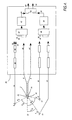
- a two-channel sound recording system includes an artificial head 2 which has in each simulated ear canal thereof a microphone (not shown). (In some artificial head arrangements, the microphone is mounted directly in lieu of the entire canal). Each microphone produces signals 4,6 (left and right channels) indicative of sounds received thereby. Spaced from the head 2 is at least one further microphone, in this example three further microphones 8,10,12. Each further microphone 8,10,12 provides a respective monophonic further signal 14,16,18 also indicative of sound received thereby.
- each microphone 8,10,12 are spaced from the head 2 by known distances - respectively d 8 , d 10 and d 12 .
- each microphone 8,10,12 is at an azimuthal angle to a point 20 at the head, which point lies on a centre line 22 through the head 2 and directly between the two ears 24,26. These angles are, respectively, for each of the microphones 8, 10 and 12; ⁇ 8 , ⁇ 10 and ⁇ 12 .
- each microphone 8,10,12 is at an angle of elevation (this term naturally includes depression) to the head given respectively by ⁇ 8 , ⁇ 10 and ⁇ 12 ; however as these angles effectively lie perpendicular the plane of the drawing they cannot be shown diagrammatically.
- the output 14 of microphone 8 passes to a signal processor shown generally as 28. Also passed to the signal processor 28 is each head 2 output 4 and 6.
- the output 14 of microphone 8 is passed to time delay 30 wherein the signal 14 is delayed by a time ⁇ 8 which depends on the time-of-flight associated with the acoustic path distance between microphone 8 and the head 2. This delay is calculated in a known manner by utilising the distance d 8 .
- the delay 30 also adds to the signal 14 a padding delay of several milliseconds, for reasons which will be explained below.
- the delayed and padded signal 32 is then passed to a filter 34 which performs binaural synthesis on signal 32.
- This filter 34 corresponds to the so-called head response transfer functions and the inter-aural time delays associated with both the azimuthal angle ⁇ 8 and elevation angle ⁇ 8 of microphone 8.
- a sound wave When a sound wave is incident on the head from a particular direction, it passes into both left and right auditory canals via a plurality of diffraction and reflection pathways around the head itself and associated with the resonances of external parts of the ear.
- the effects of this are that (a) there is a "time-of-arrival" difference between left and right ears, dependent on source position, typically between 0 and 760 ⁇ s; and (b) a great deal of spectral shaping occurs, which is also source position dependent.
- Filter 34 is constituted by such a filter pair.
- each filter 40,42 modifies its input signal 4,6 respectively in accordance with an air-to-ear transfer function for that particular ear for the artificial head (or real head, if the transfer functions derive from measurements on a real head).
- the characteristic of each filter 40,42 is in fact the inverse of the relevant transfer function.
- the reason for this, as explained hereabove, is to eliminate the "twice through the ears" effect which would otherwise be manifest.
- the outputs of the filters 40,42 are so-called equalised left 44 and right 46 channel signals.
- the delay 30 imparts to the signal 14, inter alia, a padding delay of several milliseconds.
- the need for this padding delay is twofold: firstly, to incorporate a small time delay which corresponds to the acoustic path distance differences between (a) the source, e.g. a musical instrument, producing the sound to be recorded and the local microphone, and (b) the source producing the sound to be recorded and the artificial head; and secondly to ensure that the sounds from the additional microphone are rendered distinctly after the same sounds via the artificial head, such that brain of the listener always localises the sound source from the latter, with the former reinforcing the latter by means of the known Haas effect.
- each adder 48,50 will have one input derived from the head 2 and one derived from each microphone 8,10,12.
- the output of each adder 48,50 is, respectively, a left channel combined signal 52 and a right channel combined signal 54.
- the signals 52,54 are then input into a transaural crosstalk compensator 56 which provides compensated left 58 and right 60 channels suitable for transmission or recording in any suitable conventional manner, including magnetic tape (both digital and analogue), and recordable-compact disc.
- a transaural crosstalk compensator 56 which provides compensated left 58 and right 60 channels suitable for transmission or recording in any suitable conventional manner, including magnetic tape (both digital and analogue), and recordable-compact disc.
- the left 52 and right 54 signals are shown at the top of the figure and pass down through the figure to ultimately provide signals 57 and 59 which, as well as being suitable for recording, may also be used directly to drive loudspeakers 58 and 60 respectively as shown in this figure to illustrate the concepts of transaural crosstalk compensation.
- a listener 62 is situated on a central axis X-X 1 will hear signals from loudspeakers 58 and 60.
- the listener's left ear will hear signal 57 via transfer function S directly from the left loudspeaker 58, and also via transfer function A, diffracted around his head (more) in his right ear and temporally delayed because of the longer source-to-ear distance, also from loudspeaker 58.
- loudspeakers 58,60 for stereophonic listening will be placed so as to subtend angles of 30° with respect to the vertex of the triangle they form with the listener (situated at the apex), and hence A and S can be established, in known manner, by direct measurement, either from the artificial head 2, or by using measurements from a real human head.
- a and S are the left- and right-ear head response transfer functions for a source in the horizontal plane subtending an azimuth angle of 30° (e.g. loudspeaker 60 in Figure 2).
- head response transfer functions which correspond to alternative angles might be chosen for particular applications, such as closely-spaced ( ⁇ 10°) television loudspeakers.
- a cancellation signal equal to the inverse of the crosstalk component, A must be introduced into the opposite (left) channel, and, because it undergoes subsequent modification by transfer function S between loudspeaker 58 and left ear 26, this must be anticipated and countered by the inclusion of a 1/S term in the crossfeed filter, hence the crossfeed filter has the function (-A/S).
- the transaural crosstalk compensated signals 57 and 59 comprise left and right channel signals which are suitable either to directly drive loudspeakers or headphones or are suitable to be recorded conventionally and later reproduced in known manner.
- a combined equalization and crosstalk cancellation scheme could be configured, if so desired, which could be used to implement items 42,40 and 56 of Figure 4 (to be described below), and components 72,68 and 56 of Figure 5 (and also items 70 and 66 if desired). Combined processing such as this could be implemented in a more compact, albeit less flexible, manner.
- the binaural synthesis performed on signal 32 by filter 34 is actually a normalised binaural synthesis.
- Reference now also to Figure 3 illustrates the various air-to-ear transfer function pairs ("pair" because the head 2 has a pair of ears) for various angles of incident sound in the horizontal plane.
- 0° incidence means that the sound source is directly in front of the head and 90° incidence means that the sound source is on one side (the right) of the head 2 lying on a line drawn straight through both ears, etc.
- the normalised binaural synthesised signals 36,38 do not possess the gross mid-range boost properties cause by the resonance of the concha and are thus suitable for mixing directly with appropriately equalised signals 44,46 from the head 2 in the adders 48,50.
- the equalising filters 40,42 equalise the unequalised artificial head 2 components present in signals 51,53 derived from adders 48,50 using the above- mentioned 1/S signal and then pass the equalised signals 52,54 on to the transaural crosstalk compensator 56 as described before but without incorporated 1/S functions.
- FIG. 5 A further modification of the Figure 4 embodiment is illustrated in Figure 5 where it can be seen that the equalising filters 40,42 have been divided such that two filters 66,68 equalise the left channel signals 51 and two filter banks 70,72 equalise the right channel signals 53.
- the signal processor 28 has been described as comprising a plurality of individual signal processing components, e.g. time delay 30, filters 34,40,42 adders 48,50, transaural crosstalk compensator 56, it will be appreciated by those skilled in the art that the signal processor 28 may itself take the form of a software controlled item, such as a digital processing engine, thereby obviating the need for a plurality of discrete components.
- artificial head any apparatus capable of mimicking the auditory responses characteristic of a human listener.
- the term also covers, for example, a real human head with microphones mounted within the ear canals. This is because the processing as described hereabove is then performed on the signals provided by the microphones in the same way as if the microphones had been mounted within, say, a wooden or plastics head.
Description
- The present invention relates to a plural-channel sound processing system and has particular, although not exclusive, relevance to such systems as may be used to record music for playback via two loudspeakers.
- The principles of sound recording such that, on playback via two spaced sound sources, a stereophonic effect is perceived have long been known. One of the commonest forms of stereophonic sound recording involves using a stereo microphone pair, with the microphones spaced-apart by a distance approximately equal to one head width. This produces an effect of being able to partially reproduce the acoustic image recorded owing to the different arrival times of various sounds between the microphone pair, owing to their separation.
- The above technique is far from satisfactory, however, and attempted improvements in stereo recording often utilised a so-called artificial head. This is an artificial lifesize head (and optionally) torso in which a pair of microphones are mounted either in substitution of the ear canals, or incorporated into simulated ear canals. The external ear parts are reproduced according to mean human dimensions and are manufactured from silicone rubber or similar material such that the sounds which the microphones record have been acoustically modified by the artificial head and ears so as to possess all of the natural sound localisation cues used by the brain. Such recording techniques have become known as binaural recordings and an example of one such technique is disclosed in, for example, US-A-4,910,779.
- Such artificial head recording techniques are known to possess remarkable acoustical properties when listened to via headphones. Sounds may be perceived as emanating from outside the listener's head, rather than inside it as with conventional stereophonic recordings which are listened to via headphones, and may also be perceived in three dimensions - even above and behind the listener's head.
- There also exist many problems associated with artificial head recordings. For example, it is known that the tonal qualities of binaural recordings are not true to life. This is due to the fact that sounds pass, effectively, through two sets of ears; those of the artificial head during recording, and those of the listener during playback. There is generally a resonance associated with the main cavity in the external ear (the concha) which occurs at a frequency of several kHz and boosts the mid-range gain of the recording and hence as a consequence of passing through the second set of ears during playback this effect is exacerbated and the sounds appear to lack both low-frequency and high-frequency content.
- In order to compensate for this "twice-through-the-ears" effect it is known to use audio filters to shape, or equalise, the spectral response of the sound recorded via the artificial head. The transfer function used for this shaping has been calculated in the prior art in many different ways and confusion seems to exist over which way is the best way to equalise the artificial head recordings. Some practitioners use headphone-to-ear transfer functions, yet these functions will differ from one headphone type to another. Some practitioners use loudspeaker-to-ear transfer functions - here the functions are dependent both upon the angle of incidence of the sound from the loudspeaker to the ear and the distance from the head to the loudspeaker. Other practitioners measure transfer functions under both free-field (anechoic) and diffuse-field (echoic) conditions and then compensate according to either the headphone-to-ear or loudspeaker-to-ear requirements.
- When playback of a binaurally recorded sound via loudspeakers occurs, it is known that a further important correction factor is needed. This is known as transaural crosstalk compensation and is also described in the acknowledged prior art. This correction factor essentially compensates for sound detected by the left ear originating from a loudspeaker nearer to the right ear and vice versa. An example of this well-known technique is disclosed in US-A-3,236,949.
- When making binaural sound recordings using an artificial head, the head is often set up so as to be in a central position in relation to the sounds which are to be recorded. In an example of recording an orchestra, the head will often be situated adjacent the conductor so that it can pick up most instruments with relative ease. However, this set up does not enable the artificial head to "focus" on one type of instrument, or sound, say the timpani. If the artificial head were moved nearer to the timpani section, then sound from some other instruments would not be recorded so well and the sound balance would be degraded.
- It is thus an object of one aspect of the present invention to make possible binaural sound recording using not only an artificial head but also at least one further microphone. Furthermore such recording should also be able to be played back via headphones and via loudspeakers and in either circumstance still possess the perceived binaural qualities without any need for modification or adaptation of conventional audio playback equipment.
- Thus according to a first aspect of the present invention there is provided a plural-channel sound processing system including:
- an artificial head having microphones in each ear for providing left and right first channel signals representative of sound received by the microphones;
- at least one further microphone spaced from the artificial head for providing monophonic further signals representative of sound received thereby;
- and a signal processor for: modifying the first signals in accordance with air-to-ear transfer functions of the artificial head to produce left and right auxiliary first channel signals; time-delaying the further signals from the or each further microphone in dependence upon the displacement of the or each further microphone from the artificial head; performing binaural synthesis on the time-delayed further signals to produce left and right channel auxiliary further signals; combining the resulting left and right auxiliary first and auxiliary further signals: and transaural crosstalk compensating the respective combined signals to produce left and right channel processed signals.
-
- Thus by provision of both an artificial head and at least one further microphone, both of which produce signals which are processed to exhibit binaural characteristics and which are both subjected to transaural crosstalk compensation, a signal for recording or transmission can be produced which, when played back via headphones and via loudspeakers, in either circumstance provides an apparently three dimensional sound image to a listener.
- According to a further aspect of the present invention there is provided a plural-channel sound processing system including:
- an artificial head having microphones in each ear for providing left and right first channel signals representative of sound received by the microphones;
- at least one further microphone spaced from the artificial head for providing monophonic further signals representative of sound received thereby;
- and a signal processor for: time delaying the further signals from the or each further microphone in dependence upon the displacement of the or each further microphone from the artificial head; performing binaural synthesis on the time-delayed further signals to produce left and right channel auxiliary further signals; combining the left and right channel first and auxiliary further signals; modifying the combined signals in accordance with air-to-ear transfer functions of the artificial head; and transaural crosstalk compensating the respective modified signals to produce left and right channel processed signals.
-
- Preferably the displacement of the or each further microphone from the artificial head comprises the distance from and the azimuthal and elevation angles to a point on a centre line through the head centrally between the ears whilst the head is in a predetermined orientation. Measurement of these parameters provides the necessary signal processing information to enable the signals from the or each further microphone to take on binaural recording properties by use of a particular binaural synthesis filter.
- Preferably the combining of the resultant first and further signals is achieved individually for the left and right channel signal components.
- According to a yet another aspect of the present invention there is provided a method of plural-channel sound processing including:
- providing, from an artificial head, left and right first channel signals representative of sound received by the head,
- providing, from at least one microphone spaced from the head, monophonic further signals representative of sound received thereby;
- modifying the first signals in accordance with air-to-ear transfer functions of the artificial head to produce left and right auxiliary first channel signals;
- time-delaying the further signals from the or each microphone in dependence upon the displacement of the or each microphone from the artificial head;
- performing binaural synthesis on the time-delayed further signals to produce left and right channel auxiliary further signals;
- combining the resulting left and right auxiliary first and auxiliary further signals;
- and transaural crosstalk compensating the respective combined signals to produce left and right channel processed signals.
-
- According to a further aspect of the present invention there is provided a method of plural-channel sound processing including:
- providing, from an artificial head, left and right channel first channel signals representative of sound received by the head;
- providing, from at least one microphone spaced from the head, monophonic further signals representative of sound received thereby;
- time-delaying the further signals from the or each microphone in dependence upon the displacement of the or each microphone from the artificial head;
- performing binaural synthesis on the time-delayed further signals to produce left and right channel auxiliary further signals;
- combining the left and right channel first and auxiliary further signals;
- modifying the combined signals in accordance with air-to-ear transfer functions of the artificial head;
- and transaural crosstalk compensating the respective modified signals to produce left and right channel processed signals.
-
- The invention will now be described, by way of example only, and with reference to the accompanying drawings, of which,
- Figure 1 shows a block diagram of a two-channel sound recording system in accordance with the present invention;
- Figure 2 shows schematically the concept of crosstalk compensation.
- Figure 3 illustrates various typical air-to-ear transfer functions for an artificial head representative of those which could be used in the present invention; and,
- Figures 4 and 5 each show alternative arrangements to the system of Figure 1;
-
- Referring firstly to Figure 1 it will be seen that a two-channel sound recording system includes an artificial head 2 which has in each simulated ear canal thereof a microphone (not shown). (In some artificial head arrangements, the microphone is mounted directly in lieu of the entire canal). Each microphone produces
signals 4,6 (left and right channels) indicative of sounds received thereby. Spaced from the head 2 is at least one further microphone, in this example threefurther microphones further microphone further signal - It can be seen that the
microphones microphone point 20 at the head, which point lies on acentre line 22 through the head 2 and directly between the twoears microphones microphone - From hereon, for reasons of clarity, the signals derived from only one of the three further microphones, 8, will be described. It will be apparent that such description is also relevant to the output signals from each of the
other microphones - The
output 14 ofmicrophone 8 passes to a signal processor shown generally as 28. Also passed to thesignal processor 28 is each head 2output - The
output 14 ofmicrophone 8 is passed totime delay 30 wherein thesignal 14 is delayed by a time τ8 which depends on the time-of-flight associated with the acoustic path distance betweenmicrophone 8 and the head 2. This delay is calculated in a known manner by utilising the distance d8. Thedelay 30 also adds to the signal 14 a padding delay of several milliseconds, for reasons which will be explained below. - The delayed and padded
signal 32 is then passed to afilter 34 which performs binaural synthesis onsignal 32. - This
filter 34 corresponds to the so-called head response transfer functions and the inter-aural time delays associated with both the azimuthal angle 8 and elevation angle 8 ofmicrophone 8. When a sound wave is incident on the head from a particular direction, it passes into both left and right auditory canals via a plurality of diffraction and reflection pathways around the head itself and associated with the resonances of external parts of the ear. The effects of this are that (a) there is a "time-of-arrival" difference between left and right ears, dependent on source position, typically between 0 and 760 µs; and (b) a great deal of spectral shaping occurs, which is also source position dependent. With a detailed knowledge of such processes filter pairs can be devised which, when both are fed in parallel with a signal, modify the signal so as to confer the respective left and right spectral shaping, together with an appropriate differential time delay, and cause the resultant signal to possess the perceived acoustic properties of a binaural source having the corresponding direction.Filter 34 is constituted by such a filter pair. - The binaural synthesis performed on
signal 32 thus imparts to the input monophonic signal binaural properties and so the output of thefilter 34 are left 36 and right 38 auxiliary further channel signals having perceived acoustic properties similar to those of the head 2outputs left channel 4 is supplied to afurther filter 40 and theright channel 6 is passed to afurther filter 42. Eachfilter input signal filter filters - In the description herebefore it has been stated that the
delay 30 imparts to thesignal 14, inter alia, a padding delay of several milliseconds. The need for this padding delay is twofold: firstly, to incorporate a small time delay which corresponds to the acoustic path distance differences between (a) the source, e.g. a musical instrument, producing the sound to be recorded and the local microphone, and (b) the source producing the sound to be recorded and the artificial head; and secondly to ensure that the sounds from the additional microphone are rendered distinctly after the same sounds via the artificial head, such that brain of the listener always localises the sound source from the latter, with the former reinforcing the latter by means of the known Haas effect. - The resulting left channel signals 36 and 44 are now simultaneously applied to a in this
example adder 48, similarly the resulting right channel signals 38 and 46 are simultaneously applied to adder 50. Theadders microphones adder microphone adder signal 52 and a right channel combinedsignal 54. - The
signals transaural crosstalk compensator 56 which provides compensated left 58 and right 60 channels suitable for transmission or recording in any suitable conventional manner, including magnetic tape (both digital and analogue), and recordable-compact disc. By reference now also to Figure 2, the principle of the transaural crosstalk compensation performed bycompensation 56 will be described. - The left 52 and right 54 signals are shown at the top of the figure and pass down through the figure to ultimately provide
signals loudspeakers listener 62 is situated on a central axis X-X1 will hear signals fromloudspeakers left loudspeaker 58, and also via transfer function A, diffracted around his head (more) in his right ear and temporally delayed because of the longer source-to-ear distance, also fromloudspeaker 58. Similarly the listener will hear signal 59 via transfer function S directly in his right ear fromloudspeaker 60 and via transfer function A, diffracted around his head and temporally delayed, in his left ear. This is clearly illustrated at the foot of Figure 2. Thus the transmission function from a loudspeaker to the ear on the same side of the central axis X-X1 is S, and to the ear on the opposite side of the central axis is A. - It is a conventional assumption that
loudspeakers e.g. loudspeaker 60 in Figure 2). As noted previously, however, head response transfer functions which correspond to alternative angles might be chosen for particular applications, such as closely-spaced (±10°) television loudspeakers. - By inspection of the lower part of Figure 2, it will be evident that, ordinarily, in a conventional stereophonic reproduction system, the
right channel signal 59 is conveyed to theright ear 24 via transmission function S, and also to theleft ear 26 as a crosstalk signal via transmission function A. Using the notation Xy for signals received at the ears, where X represents the source channel and y represents which ear (right or left) is under consideration, then this can be represented as: - In order to convey the signals to the listener without the crosstalk component, then the following must obtain:
- In order to implement this, firstly in respect of the
right channel signal 54, and as is shown in the upper part of Figure 2, a cancellation signal equal to the inverse of the crosstalk component, A, must be introduced into the opposite (left) channel, and, because it undergoes subsequent modification by transfer function S betweenloudspeaker 58 and leftear 26, this must be anticipated and countered by the inclusion of a 1/S term in the crossfeed filter, hence the crossfeed filter has the function (-A/S). - However, the cancellation signal of each of the
loudspeakers right ear 24 oflistener 62 should be equal to S:
- The overall transmission function from the right 54 signal to the
left ear 26 of the listener, is equal to 0, whatever the value of G:
- By solving (3) for G in terms of A and S, it can be shown that:

- Hence by constructing the
compensator 56 of Figure 1 to perform the functions described with reference to Figure 2 the transaural crosstalk compensated signals 57 and 59 comprise left and right channel signals which are suitable either to directly drive loudspeakers or headphones or are suitable to be recorded conventionally and later reproduced in known manner. - It is also known that transaural crosstalk cancellation means can be devised so as to include equalization, for example, of the sounds originating from loudspeakers at any given angle, such as ± 30°. This is achieved by solving equation (2) for unity and zero (rather than S and zero) thus:
- Accordingly, a combined equalization and crosstalk cancellation scheme could be configured, if so desired, which could be used to implement
items components items 70 and 66 if desired). Combined processing such as this could be implemented in a more compact, albeit less flexible, manner. - It should be noted that the binaural synthesis performed on
signal 32 byfilter 34 is actually a normalised binaural synthesis. This means that the synthesis utilises the air-to-ear transfer function pair for a particular direction (8,8) divided by the corresponding air-to-ear transfer function pair for frontal sound incidence (i.e. =0 and =0). Reference now also to Figure 3 illustrates the various air-to-ear transfer function pairs ("pair" because the head 2 has a pair of ears) for various angles of incident sound in the horizontal plane. 0° incidence means that the sound source is directly in front of the head and 90° incidence means that the sound source is on one side (the right) of the head 2 lying on a line drawn straight through both ears, etc. - It will be appreciated that the normalised binaural synthesised signals 36,38 do not possess the gross mid-range boost properties cause by the resonance of the concha and are thus suitable for mixing directly with appropriately equalised signals 44,46 from the head 2 in the
adders - Referring now to Figure 4, which shows an alternative embodiment to that of Figure 1 and so like components are correspondingly numbered, it can be seen that equalisation of the
signals adders signals 32 are passed to afilter 64 which performs an ordinary, i.e. not normalised, binaural synthesis thereupon. Clearly the normalisation is not necessary in this particular case as the equalisation performed subsequently by thefilter adders transaural crosstalk compensator 56 as described before but without incorporated 1/S functions. - A further modification of the Figure 4 embodiment is illustrated in Figure 5 where it can be seen that the equalising filters 40,42 have been divided such that two
filters - It will be apparent that in relation to the foregoing description, the
individual microphone time delay elements 30 adjusted accordingly. - Those skilled in the art will appreciate that, in the foregoing, the choice of which particular air-to-ear transfer function, as illustrated in Figure 3, is to be chosen will be dictated by the particular circumstances of the recording to be made. For example, if the recording is intended to be played back via headphones, which generally cup around the listener's ears, then the 90° air-to-ear transfer functions will be used in order to equalise the signals provided. However, in the above example, the recording is desired to be primarily played back via loudspeakers, each of which subtends an angle of approximately 30° from the mid-line at the listener's ears, and so the 30° air-to-ear transfer functions have been chosen. It is important to note, however, that sound recorded by the apparatus described may equally well be perceived as three-dimensional whether played back through either headphones or loudspeakers - substantially independent of whichever transfer functions have been chosen to equalise the signals. It must also be realised that the air-to-ear transfer functions used on signals provided by the further microphones in order to provide the binaural synthesis are dictated by and .
- It will be understood that, although in the above description three further microphones spaced from the artificial head have been described - one in particular - the present invention is equally applicable with a considerable number of additional microphones, so long as the signal from each is subjected to the necessary time-delays and binaural synthesis before being combined with the signals provided by the artificial head.
- Whilst in the above example, the
signal processor 28 has been described as comprising a plurality of individual signal processing components,e.g. time delay 30, filters 34,40,42adders transaural crosstalk compensator 56, it will be appreciated by those skilled in the art that thesignal processor 28 may itself take the form of a software controlled item, such as a digital processing engine, thereby obviating the need for a plurality of discrete components. - It will be apparent that the said transfer functions can be derived both by measurements on artificial heads and also on real human heads.
- Furthermore, although in the above description, 30° has been given as the primary example of the angle subtended at the head 2 by the loudspeakers, it will be apparent that any suitable angle may be equally well employed.
- Those skilled in the art will appreciate that by the term artificial head is meant any apparatus capable of mimicking the auditory responses characteristic of a human listener. Thus the term also covers, for example, a real human head with microphones mounted within the ear canals. This is because the processing as described hereabove is then performed on the signals provided by the microphones in the same way as if the microphones had been mounted within, say, a wooden or plastics head.
Claims (13)
- A plural-channel sound processing apparatus including:an artificial head (2) having microphones in each ear (24,26) for providing left (4) and right (6) first channel signals representative of sound received by the microphones;at least one further microphone (8) spaced from the artificial head for providing monophonic further signals (14) representative of sound received thereby;and a signal processing means (28) for: modifying (40,42) the first channel signals in accordance with air-to-ear transfer functions of the artificial head to produce left and right auxiliary first channel signals (44,46); time-delaying (30) the further signals from the or each further microphone in dependence upon the displacement of the or each further microphone from the artificial head; performing binaural synthesis (34) on the time-delayed further signals to produce left and right channel auxiliary further signals(36,38); combining (48,50) the resulting left and right auxiliary first and auxiliary further signals: and transaural crosstalk compensating (56) the respective combined signals to produce left and right channel processed signals (58,60).
- A plural-channel sound processing apparatus including:an artificial head (2) having microphones in each ear (24,26) for providing left (4) and right (6) first channel signals representative of sound received by the microphones;at least one further microphone (8) spaced from the artificial head for providing monophonic further signals (14) representative of sound received thereby;and a signal processing means (28) for: time delaying (30) the further signals from the or each further microphone in dependence upon the displacement of the or each further microphone from the artificial head; performing binaural synthesis (34) on the time-delayed further signals to produce left and right channel auxiliary further signals (36,38); combining (48,50) the left and right channel first and auxiliary further signals; modifying (40,42) the combined signals in accordance with air-to-ear transfer functions of the artificial head; and transaural crosstalk compensating (56) the respective modified signals to produce left and right channel processed signals.
- An apparatus according to either Claim 1 or Claim 2 wherein the displacement of the or each further microphone from the artificial head comprises the distance (d) from and the azimuthal (Θ) and elevation () angles to a point (20) on a centre line (22) through the head centrally between the ears whilst the head is in a predetermined orientation.
- An apparatus according to claim 1 wherein the signal processing means includes means for combining the left channel signal components and for combining the right channel signal components.
- An apparatus according to claim 2 wherein the signal processing means includes means for combining the left channel signal components and for combining the right channel signal components.
- An apparatus according to claim 1 wherein the signal processing means comprises
a first filter means (40,42) for modifying the first signals in accordance with air-to-ear transfer functions of the artificial head; a time delay means (30) for delaying the further signals from the or each microphone; a second filters means (34) for performing said binaural synthesis; an adder means (48,50) for combining the signals; and a transaural crosstalk compensator means (56). - An apparatus according to claim 2 wherein the signal processing means comprises
a first filter means (40,42) for modifying the signals in accordance with air-to-ear transfer functions of the artificial head; a time delay means (30) for delaying the further signals from the or each microphone; a second filter means (64) for performing the binaural synthesis; an adder means (48,50) for combining the signals; and a transaural crosstalk compensator means (56). - An apparatus according to Claim 1 wherein the signal processing means includes means for performing a normalised binaural synthesis.
- An apparatus according to Claim 2 wherein the signal processing means includes means for performing a normalised binaural synthesis.
- A method of plural-channel sound processing including:providing, from an artificial head (2), left (4) and right (6) first channel signals representative of sound received by the head,providing, from at least one microphone (8) spaced from the head, monophonic further signals (14) representative of sound received thereby;modifying (40,42) the first signals in accordance with air-to-ear transfer functions of the artificial head to produce left (44) and right (46) auxiliary first channel signals;time-delaying (30) the further signals from the or each microphone in dependence upon the displacement of the or each microphone from the artificial head;performing binaural synthesis (34) on the time-delayed further signals to produce left (36) and right (38) channel auxiliary further signals;combining (48) the resulting left auxiliary first and auxiliary further signals, and combining (50) the resulting right auxiliary first and auxiliary further signals; andtransaural crosstalk compensating and combining (56) the respective combined signals to produce left and right channel processed signals.
- A method of plural-channel sound processing including:providing, from an artificial head (2), left (4) and right (6) channel first channel signals representative of sound received by the head;providing, from at least one microphone (8) spaced from the head, monophonic further signals (14) representative of sound received thereby;time-delaying (30) the further signals from the or each microphone in dependence upon the displacement of the or each microphone from the artificial head;performing binaural synthesis (64) on the time-delayed further signals to produce left (36) and right (38) channel auxiliary further signals;combining (48) the left channel first and auxiliary further signals and combining (50) the right channel first and auxiliary further signals;modifying(40, 42) the combined signals in accordance with air-toear transfer functions of the artificial head;and transaural crosstalk compensating (56) the respective modified signals to produce left and right channel processed signals.
- Use of the apparatus according to any of claims 1 to 9 for recording or transmitting sound.
- Use of the method according to claim 10 or claim 11 for recording or transmitting sound.
Applications Claiming Priority (5)
| Application Number | Priority Date | Filing Date | Title |
|---|---|---|---|
| GB9305583A GB2276298A (en) | 1993-03-18 | 1993-03-18 | Plural-channel sound processing |
| GB9305583 | 1993-03-18 | ||
| GB9308509 | 1993-04-23 | ||
| GB939308509A GB9308509D0 (en) | 1993-04-23 | 1993-04-23 | Plural-channel sound processing |
| PCT/GB1994/000350 WO1994022278A1 (en) | 1993-03-18 | 1994-02-23 | Plural-channel sound processing |
Publications (2)
| Publication Number | Publication Date |
|---|---|
| EP0689756A1 EP0689756A1 (en) | 1996-01-03 |
| EP0689756B1 true EP0689756B1 (en) | 1999-10-27 |
Family
ID=26302610
Family Applications (1)
| Application Number | Title | Priority Date | Filing Date |
|---|---|---|---|
| EP94907618A Expired - Lifetime EP0689756B1 (en) | 1993-03-18 | 1994-02-23 | Plural-channel sound processing |
Country Status (6)
| Country | Link |
|---|---|
| US (1) | US5666425A (en) |
| EP (1) | EP0689756B1 (en) |
| JP (1) | JPH08507910A (en) |
| CA (1) | CA2158451A1 (en) |
| DE (1) | DE69421385T2 (en) |
| WO (1) | WO1994022278A1 (en) |
Families Citing this family (32)
| Publication number | Priority date | Publication date | Assignee | Title |
|---|---|---|---|---|
| GB9324240D0 (en) | 1993-11-25 | 1994-01-12 | Central Research Lab Ltd | Method and apparatus for processing a bonaural pair of signals |
| US5764778A (en) * | 1995-06-07 | 1998-06-09 | Sensimetrics Corporation | Hearing aid headset having an array of microphones |
| GB9610394D0 (en) * | 1996-05-17 | 1996-07-24 | Central Research Lab Ltd | Audio reproduction systems |
| US6130949A (en) * | 1996-09-18 | 2000-10-10 | Nippon Telegraph And Telephone Corporation | Method and apparatus for separation of source, program recorded medium therefor, method and apparatus for detection of sound source zone, and program recorded medium therefor |
| DE19645867A1 (en) * | 1996-11-07 | 1998-05-14 | Deutsche Telekom Ag | Multiple channel sound transmission method |
| WO1998042161A2 (en) * | 1997-03-18 | 1998-09-24 | Central Research Laboratories Limited | Telephonic transmission of three-dimensional sound |
| US6072878A (en) * | 1997-09-24 | 2000-06-06 | Sonic Solutions | Multi-channel surround sound mastering and reproduction techniques that preserve spatial harmonics |
| GB9726338D0 (en) * | 1997-12-13 | 1998-02-11 | Central Research Lab Ltd | A method of processing an audio signal |
| GB2337676B (en) * | 1998-05-22 | 2003-02-26 | Central Research Lab Ltd | Method of modifying a filter for implementing a head-related transfer function |
| GB2343347B (en) * | 1998-06-20 | 2002-12-31 | Central Research Lab Ltd | A method of synthesising an audio signal |
| DE19847689B4 (en) * | 1998-10-15 | 2013-07-11 | Samsung Electronics Co., Ltd. | Apparatus and method for three-dimensional sound reproduction |
| US6442277B1 (en) * | 1998-12-22 | 2002-08-27 | Texas Instruments Incorporated | Method and apparatus for loudspeaker presentation for positional 3D sound |
| GB2351213B (en) * | 1999-05-29 | 2003-08-27 | Central Research Lab Ltd | A method of modifying one or more original head related transfer functions |
| JP3584800B2 (en) * | 1999-08-17 | 2004-11-04 | ヤマハ株式会社 | Sound field reproduction method and apparatus |
| GB2353926B (en) * | 1999-09-04 | 2003-10-29 | Central Research Lab Ltd | Method and apparatus for generating a second audio signal from a first audio signal |
| JP3689041B2 (en) * | 1999-10-28 | 2005-08-31 | 三菱電機株式会社 | 3D sound field playback device |
| US6845163B1 (en) * | 1999-12-21 | 2005-01-18 | At&T Corp | Microphone array for preserving soundfield perceptual cues |
| AT411123B (en) * | 2000-03-21 | 2003-09-25 | Joanneum Res Forschungsgmbh | DEVICE FOR RECORDING SOUND WAVES |
| US6928168B2 (en) | 2001-01-19 | 2005-08-09 | Nokia Corporation | Transparent stereo widening algorithm for loudspeakers |
| JP2005223713A (en) * | 2004-02-06 | 2005-08-18 | Sony Corp | Apparatus and method for acoustic reproduction |
| JP4449998B2 (en) * | 2007-03-12 | 2010-04-14 | ヤマハ株式会社 | Array speaker device |
| JP4488036B2 (en) * | 2007-07-23 | 2010-06-23 | ヤマハ株式会社 | Speaker array device |
| JP5577597B2 (en) * | 2009-01-28 | 2014-08-27 | ヤマハ株式会社 | Speaker array device, signal processing method and program |
| JP2011120028A (en) * | 2009-12-03 | 2011-06-16 | Canon Inc | Sound reproducer and method for controlling the same |
| KR101827032B1 (en) | 2010-10-20 | 2018-02-07 | 디티에스 엘엘씨 | Stereo image widening system |
| WO2012094335A1 (en) | 2011-01-04 | 2012-07-12 | Srs Labs, Inc. | Immersive audio rendering system |
| US20150036827A1 (en) * | 2012-02-13 | 2015-02-05 | Franck Rosset | Transaural Synthesis Method for Sound Spatialization |
| US10321252B2 (en) | 2012-02-13 | 2019-06-11 | Axd Technologies, Llc | Transaural synthesis method for sound spatialization |
| GB2574946B (en) * | 2015-10-08 | 2020-04-22 | Facebook Inc | Binaural synthesis |
| GB2544458B (en) | 2015-10-08 | 2019-10-02 | Facebook Inc | Binaural synthesis |
| EP3448066A4 (en) * | 2016-04-21 | 2019-12-25 | Socionext Inc. | Signal processor |
| US11256768B2 (en) | 2016-08-01 | 2022-02-22 | Facebook, Inc. | Systems and methods to manage media content items |
Family Cites Families (8)
| Publication number | Priority date | Publication date | Assignee | Title |
|---|---|---|---|---|
| US3236949A (en) * | 1962-11-19 | 1966-02-22 | Bell Telephone Labor Inc | Apparent sound source translator |
| US4096353A (en) * | 1976-11-02 | 1978-06-20 | Cbs Inc. | Microphone system for producing signals for quadraphonic reproduction |
| US4893342A (en) * | 1987-10-15 | 1990-01-09 | Cooper Duane H | Head diffraction compensated stereo system |
| US4910779A (en) * | 1987-10-15 | 1990-03-20 | Cooper Duane H | Head diffraction compensated stereo system with optimal equalization |
| US5034983A (en) * | 1987-10-15 | 1991-07-23 | Cooper Duane H | Head diffraction compensated stereo system |
| JPH0219400A (en) * | 1988-07-07 | 1990-01-23 | Green Cross Corp:The | Production of thrombin or prothronbin |
| US5173944A (en) * | 1992-01-29 | 1992-12-22 | The United States Of America As Represented By The Administrator Of The National Aeronautics And Space Administration | Head related transfer function pseudo-stereophony |
| DE9208988U1 (en) * | 1992-07-04 | 1992-10-29 | Head Acoustics Gmbh Kopfbezogene Aufnahme- Und Wiedergabetechnik, Messtechnik, 5120 Herzogenrath, De |
-
1994
- 1994-02-23 WO PCT/GB1994/000350 patent/WO1994022278A1/en active IP Right Grant
- 1994-02-23 US US08/507,437 patent/US5666425A/en not_active Expired - Lifetime
- 1994-02-23 JP JP6520742A patent/JPH08507910A/en not_active Ceased
- 1994-02-23 CA CA002158451A patent/CA2158451A1/en not_active Abandoned
- 1994-02-23 DE DE69421385T patent/DE69421385T2/en not_active Expired - Fee Related
- 1994-02-23 EP EP94907618A patent/EP0689756B1/en not_active Expired - Lifetime
Also Published As
| Publication number | Publication date |
|---|---|
| DE69421385D1 (en) | 1999-12-02 |
| CA2158451A1 (en) | 1994-09-29 |
| US5666425A (en) | 1997-09-09 |
| JPH08507910A (en) | 1996-08-20 |
| DE69421385T2 (en) | 2000-04-06 |
| WO1994022278A1 (en) | 1994-09-29 |
| EP0689756A1 (en) | 1996-01-03 |
Similar Documents
| Publication | Publication Date | Title |
|---|---|---|
| EP0689756B1 (en) | Plural-channel sound processing | |
| US6611603B1 (en) | Steering of monaural sources of sound using head related transfer functions | |
| KR100416757B1 (en) | Multi-channel audio reproduction apparatus and method for loud-speaker reproduction | |
| US4119798A (en) | Binaural multi-channel stereophony | |
| US6574339B1 (en) | Three-dimensional sound reproducing apparatus for multiple listeners and method thereof | |
| US6614910B1 (en) | Stereo sound expander | |
| US5333200A (en) | Head diffraction compensated stereo system with loud speaker array | |
| KR100644617B1 (en) | Apparatus and method for reproducing 7.1 channel audio | |
| US8027476B2 (en) | Sound reproduction apparatus and sound reproduction method | |
| EP0730812B1 (en) | Apparatus for processing binaural signals | |
| EP0814638B1 (en) | Three-dimensional sound reproducing apparatus and a three-dimensional sound reproduction method | |
| JPH10509565A (en) | Recording and playback system | |
| JP3920404B2 (en) | Audio playback module | |
| JP2000050400A (en) | Processing method for sound image localization of audio signals for right and left ears | |
| US6009178A (en) | Method and apparatus for crosstalk cancellation | |
| US6222930B1 (en) | Method of reproducing sound | |
| JP2003230198A (en) | Sound image localization control device | |
| JP4744695B2 (en) | Virtual sound source device | |
| GB2276298A (en) | Plural-channel sound processing | |
| JPH06217400A (en) | Acoustic equipment | |
| KR100307622B1 (en) | Audio playback device using virtual sound image with adjustable position and method | |
| JPH07193899A (en) | Stereo headphone device for controlling three-dimension sound field | |
| Sibbald | Transaural acoustic crosstalk cancellation | |
| JP2003111198A (en) | Voice signal processing method and voice reproducing system | |
| JPH06233394A (en) | Surround signal processing unit |
Legal Events
| Date | Code | Title | Description |
|---|---|---|---|
| PUAI | Public reference made under article 153(3) epc to a published international application that has entered the european phase |
Free format text: ORIGINAL CODE: 0009012 |
|
| 17P | Request for examination filed |
Effective date: 19950908 |
|
| AK | Designated contracting states |
Kind code of ref document: A1 Designated state(s): DE FR GB NL |
|
| GRAG | Despatch of communication of intention to grant |
Free format text: ORIGINAL CODE: EPIDOS AGRA |
|
| GRAG | Despatch of communication of intention to grant |
Free format text: ORIGINAL CODE: EPIDOS AGRA |
|
| GRAH | Despatch of communication of intention to grant a patent |
Free format text: ORIGINAL CODE: EPIDOS IGRA |
|
| 17Q | First examination report despatched |
Effective date: 19990301 |
|
| GRAH | Despatch of communication of intention to grant a patent |
Free format text: ORIGINAL CODE: EPIDOS IGRA |
|
| GRAA | (expected) grant |
Free format text: ORIGINAL CODE: 0009210 |
|
| AK | Designated contracting states |
Kind code of ref document: B1 Designated state(s): DE FR GB NL |
|
| REF | Corresponds to: |
Ref document number: 69421385 Country of ref document: DE Date of ref document: 19991202 |
|
| ET | Fr: translation filed | ||
| PGFP | Annual fee paid to national office [announced via postgrant information from national office to epo] |
Ref country code: DE Payment date: 20000422 Year of fee payment: 7 |
|
| PGFP | Annual fee paid to national office [announced via postgrant information from national office to epo] |
Ref country code: NL Payment date: 20000731 Year of fee payment: 7 |
|
| PLBE | No opposition filed within time limit |
Free format text: ORIGINAL CODE: 0009261 |
|
| STAA | Information on the status of an ep patent application or granted ep patent |
Free format text: STATUS: NO OPPOSITION FILED WITHIN TIME LIMIT |
|
| 26N | No opposition filed | ||
| PGFP | Annual fee paid to national office [announced via postgrant information from national office to epo] |
Ref country code: FR Payment date: 20010530 Year of fee payment: 8 |
|
| PG25 | Lapsed in a contracting state [announced via postgrant information from national office to epo] |
Ref country code: NL Free format text: LAPSE BECAUSE OF NON-PAYMENT OF DUE FEES Effective date: 20010901 |
|
| NLV4 | Nl: lapsed or anulled due to non-payment of the annual fee |
Effective date: 20010901 |
|
| PG25 | Lapsed in a contracting state [announced via postgrant information from national office to epo] |
Ref country code: DE Free format text: LAPSE BECAUSE OF NON-PAYMENT OF DUE FEES Effective date: 20011201 |
|
| REG | Reference to a national code |
Ref country code: GB Ref legal event code: IF02 |
|
| PGFP | Annual fee paid to national office [announced via postgrant information from national office to epo] |
Ref country code: GB Payment date: 20020128 Year of fee payment: 9 |
|
| PG25 | Lapsed in a contracting state [announced via postgrant information from national office to epo] |
Ref country code: GB Free format text: LAPSE BECAUSE OF NON-PAYMENT OF DUE FEES Effective date: 20030223 |
|
| GBPC | Gb: european patent ceased through non-payment of renewal fee | ||
| PG25 | Lapsed in a contracting state [announced via postgrant information from national office to epo] |
Ref country code: FR Free format text: LAPSE BECAUSE OF NON-PAYMENT OF DUE FEES Effective date: 20031031 |
|
| REG | Reference to a national code |
Ref country code: FR Ref legal event code: ST |
|
| PG25 | Lapsed in a contracting state [announced via postgrant information from national office to epo] |
Ref country code: FR Free format text: LAPSE BECAUSE OF NON-PAYMENT OF DUE FEES Effective date: 20020228 |