EP0689745B1 - Method for synchronizing interconnected sdh and pdh telecommunications networks - Google Patents
Method for synchronizing interconnected sdh and pdh telecommunications networks Download PDFInfo
- Publication number
- EP0689745B1 EP0689745B1 EP94909143A EP94909143A EP0689745B1 EP 0689745 B1 EP0689745 B1 EP 0689745B1 EP 94909143 A EP94909143 A EP 94909143A EP 94909143 A EP94909143 A EP 94909143A EP 0689745 B1 EP0689745 B1 EP 0689745B1
- Authority
- EP
- European Patent Office
- Prior art keywords
- network
- pdh
- synchronization
- sdh
- signal
- Prior art date
- Legal status (The legal status is an assumption and is not a legal conclusion. Google has not performed a legal analysis and makes no representation as to the accuracy of the status listed.)
- Expired - Lifetime
Links
- 238000000034 method Methods 0.000 title claims abstract description 14
- 230000001360 synchronised effect Effects 0.000 claims description 10
- 230000003139 buffering effect Effects 0.000 claims 2
- 230000005540 biological transmission Effects 0.000 description 1
- 238000004891 communication Methods 0.000 description 1
- 230000008878 coupling Effects 0.000 description 1
- 238000010168 coupling process Methods 0.000 description 1
- 238000005859 coupling reaction Methods 0.000 description 1
- 238000005516 engineering process Methods 0.000 description 1
Images


Classifications
-
- H—ELECTRICITY
- H04—ELECTRIC COMMUNICATION TECHNIQUE
- H04J—MULTIPLEX COMMUNICATION
- H04J3/00—Time-division multiplex systems
- H04J3/02—Details
- H04J3/06—Synchronising arrangements
- H04J3/0635—Clock or time synchronisation in a network
- H04J3/0679—Clock or time synchronisation in a network by determining clock distribution path in a network
-
- H—ELECTRICITY
- H04—ELECTRIC COMMUNICATION TECHNIQUE
- H04J—MULTIPLEX COMMUNICATION
- H04J3/00—Time-division multiplex systems
- H04J3/02—Details
- H04J3/06—Synchronising arrangements
- H04J3/0635—Clock or time synchronisation in a network
- H04J3/0638—Clock or time synchronisation among nodes; Internode synchronisation
- H04J3/0647—Synchronisation among TDM nodes
-
- H—ELECTRICITY
- H04—ELECTRIC COMMUNICATION TECHNIQUE
- H04L—TRANSMISSION OF DIGITAL INFORMATION, e.g. TELEGRAPHIC COMMUNICATION
- H04L12/00—Data switching networks
- H04L12/28—Data switching networks characterised by path configuration, e.g. LAN [Local Area Networks] or WAN [Wide Area Networks]
- H04L12/42—Loop networks
- H04L12/422—Synchronisation for ring networks
-
- H—ELECTRICITY
- H04—ELECTRIC COMMUNICATION TECHNIQUE
- H04Q—SELECTING
- H04Q11/00—Selecting arrangements for multiplex systems
- H04Q11/04—Selecting arrangements for multiplex systems for time-division multiplexing
- H04Q11/0428—Integrated services digital network, i.e. systems for transmission of different types of digitised signals, e.g. speech, data, telecentral, television signals
- H04Q11/0478—Provisions for broadband connections
-
- H—ELECTRICITY
- H04—ELECTRIC COMMUNICATION TECHNIQUE
- H04J—MULTIPLEX COMMUNICATION
- H04J2203/00—Aspects of optical multiplex systems other than those covered by H04J14/05 and H04J14/07
- H04J2203/0001—Provisions for broadband connections in integrated services digital network using frames of the Optical Transport Network [OTN] or using synchronous transfer mode [STM], e.g. SONET, SDH
- H04J2203/0057—Operations, administration and maintenance [OAM]
- H04J2203/006—Fault tolerance and recovery
-
- H—ELECTRICITY
- H04—ELECTRIC COMMUNICATION TECHNIQUE
- H04J—MULTIPLEX COMMUNICATION
- H04J2203/00—Aspects of optical multiplex systems other than those covered by H04J14/05 and H04J14/07
- H04J2203/0001—Provisions for broadband connections in integrated services digital network using frames of the Optical Transport Network [OTN] or using synchronous transfer mode [STM], e.g. SONET, SDH
- H04J2203/0089—Multiplexing, e.g. coding, scrambling, SONET
Definitions
- the invention relates to a method for synchronizing interconnected SDH and PDH telecommunications networks.
- Document EP 522 748 shows a SDH data transmission timing means where the bearer rate signal is estimated through the system by synchronizing successive equipment in the network path and subsequently deriving from the final bearer a timing signal back at the original frequency.
- the object of the present invention is to provide a method by means of which it is possible to transmit a timing (synchronization) between the SDH and PDH networks in such a way that a master node is found with the greatest possible certainty also in failure cases.
- This object is achieved by means of the method of the invention, which is characterized in what is described in the characterizing portion of the enclosed claim 1.
- the basic idea according to the invention is that the SDH and PDH networks are synchronised by synchronizing the PDH network with the SDH network, whereby the method according to the invention comprises:
- a synchronization may be performed either by means of separate synchronizing connections or by utilizing normal data connections between the nodes (devices) of the system. Separate synchronizing connections are used in individual cases only and very seldom for the synchronization of a whole network.
- data connections are used for the synchronization, such a line code is needed that the nodes are capable of extracting also the clock frequency of an incoming data signal.
- the synchronization of the nodes of the network may be performed by two different basic methods: mutual synchronization and master-slave synchronization.
- mutual synchronization each node generates its own clock frequency from the average of the frequencies of incoming signals and its own clock frequency at the moment.
- all nodes of the network are driven towards a common average frequency and in a stable state they have achieved it.
- a network using mutual synchronization cannot be synchronized with a desired source, which makes an interconnection of different networks problematic, because the operating frequency of the whole network cannot then be predetermined accurately.
- master-slave synchronization instead, all nodes of the network are synchronized with the clock frequency of one master node. Each node selects the frequency of one incoming signal as the source of its own clock frequency. The node tries to select a signal having the clock frequency of the master node of the network.
- each node makes its own decision on synchronization, without receiving any information supporting the decision-making from outside. Since the nodes make their decisions on synchronization independently, each node must be provided with definitions of with which node to be synchronized. These definitions are often made in the form of a priority list, whereby a node selects that signal from the usable incoming signals as the source of its synchronization which has the highest priority, i.e. the one which is highest on the list. If this signal is interrupted or its quality becomes weaker so that it cannot be qualified as the source of synchronization any longer, the node selects from the list the signal which has the next highest priority.
- the priority list shall be composed in such a way that all nodes on it are situated between the node in question and the master node, whereby the synchronization spreads from the master node to lower levels.
- independent master-slave synchronization causes restrictions for the synchronization of the network: in a loop network, all connections cannot be used for the synchronization, due to which the dynamic adaptability of the network is restricted in different situations. Communication has to be brought between the nodes for the purpose that the amount of information of a separate node would be sufficient for decision-making in all situations, without a necessity of restricting heavily the amount of connections to be used for the synchronization, in which case the clock frequency of the master node cannot be spread equally well to the nodes of the network in failure conditions.
- LP synchronization tries to prevent the timing of loop networks from getting in disorder by using two status bits mcb and lcb to support the above-mentioned priority lists, which bits are transmitted between the nodes of the network.
- the first status bit mcb (master control bit) indicates whether the synchronization comes from the master node of the network.
- the master node defined for the network transmits this bit as a logic zero in its outgoing signals and the other nodes transmit it forward, in case they are synchronized with a signal the value of the mcb of which is zero.
- the second status bit lcb (loop control bit) indicates whether there is a loop in the synchronization.
- Each node of the network transmits this bit as a logic number one in the direction with which the node itself is synchronized and as a logic zero in the other directions.
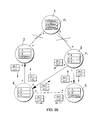
- Figure 1 shows an example of a telecommunications network comprising five nodes 1 to 5, which network uses the LP synchronization described above.
- the bits mcb and lcb transmitted by each node in different directions are indicated at the nodes by reference marks M (mcb) and L (lcb), respectively.
- M (mcb) and L (lcb) are indicated at the nodes by reference marks M (mcb) and L (lcb), respectively.
- a synchronization tree is composed of tree-like hierarchic structures, while in LP synchronization the synchronization tree is composed by means of loops.
- a master loop in which the master node of the network is situated, and then nodes are added to the synchronization tree chain by chain, until all nodes are included.
- Priority lists are composed according to the loops and chains.
- the master loop comprises the nodes 1, 2, 4 and 3, in this order.
- To this master loop is connected a one node chain (node 5).
- the priority lists used by the nodes are indicated by reference mark PL.
- Reference marks A, B and C designate incoming signals of each node.
- the connections not used by the synchronization are indicated by broken lines in the figure.
- Figures 2a to 2c illustrate the behaviour of a network using LP synchronization (Figure 1) in a failure condition.
- the connection between the master node 1 and the node 2 is interrupted.
- the network receives synchronization from the master node 1 via the node 3.
- the connection is interrupted also between the nodes 1 and 3, whereby the new master node will be the node 3, which was the last to forward the frequency of the master node to the network.
- the mcb sent by the node 3 has now changed into a logic number one to indicate that there exists no connection with the official master node of the network any longer.
- the failure between the nodes 1 and 3 is repaired and the network is resynchronized with its original master node.
- SOH Section OverHead
- FIG. 3 shows a SDH network 31 and a PDH network 32, which are interconnected by coupling a device 33 of the SDH network to nodes 34 and 35 of the PDH network.
- a typical SDH device 33 comprises 63 interfaces of 2048 kbit/s (because an STM-1 frame typically includes 63 channels of 2048 kbit/s).
- a signal to be transmitted to such a PDH network is provided in the SDH device with status bits mcb and lcb to be used for LP synchronization in such a way that these bits are interpretable in the PDH network (in a node of the PDH network) by using rules of interpretation known per se.
- a common "synchronization" language can thus be constructed between the networks without a necessity of making changes in the PDH network.
- Such status bits are not necessarily used in all signals to be transferred from the SDH network to the PDH network, but the timing is indicated typically in one direction or two directions (depending on the topology of the network).
- the status bits mcb and lcb may be transferred e.g.
- the status bits may be added to the 2048 kbit/s signal by generating them by means of software in an output buffer of this 2048 kbit/s signal.
- the bits may be detected by reading them by means of software from an input buffer of the 2048 kbit/s signal.
- Figure 4 shows the principle of the invention concerning timing in a loop network, which comprises a node 33 of a SDH network and nodes 34, 35 and 36 of a PDH network.
- the master node of the whole network is in this case the node 33, a clock signal of a clock oscillator 33a of which is transmitted over a loop 37 to 35 synchronizing means (34a, 36a and 35a) of all other nodes, whereby an outgoing signal of each node has the same frequency ⁇ defined by the master node 33 of the network.
- the status bits transmitted by the node 33 to the PDH network have the value "0", because the node 33 has been defined as the master node of the interconnected network.
Abstract
Description
| Timing of SDH network | lcb value | mcb value |
| | 0 | 0 |
| | 0 | 0 |
| | 1 | 0 |
| | 0 | 1 |
| Timing of SDH network | lcb value |
| | 0 |
| | 0 |
| | 1 |
| | 0 |
- external I: timing from an external clock oscillator, a device (node) being defined as the master node of interconnected SDH and PDH networks,
- internal I: timing from an internal clock oscillator and a device (node) defined as the master node of the interconnected SDH and PDH networks,
- external II: the SDH network receives its timing from a clock signal coming from the PDH network to the SDH network, and
- internal II: timing from an internal clock oscillator.
Claims (3)
- A method for synchronizing interconnected Synchronous Digital Hierarchy (SDH) and Plesiochronous Digital Hierarchy (PDH) telecommunications networks (31, 32), characterized in that the SDH and PDH networks are synchronised by synchronizing the PDH network with the SDH network, whereby the method comprises:providing a signal to be transmitted to a PDH network in a device (33) of the SDH network (31) connected to the PDH network with at least one status bit (lcb, mcb) for Loop Protected (LP) synchronization,receiving the signal at the PDH network,detecting the at least one status bit from the received signal by using rules of interpretation, andsynchronizing the PDH network with the SDH network using the detected at least one status bit for LP synchronization.
- A method according to claim 1, characterized in that the method further comprises:
adding to the signal to be transmitted from the SDH network (31) to the PDH network (32) both a loop control bit (lcb) indicating whether there is a loop in the synchronization and a master control bit (mcb) indicating whether the synchronization comes from the master node of the interconnected network. - A method according to claim 1 or 2, characterized in that the method further comprises:buffering the signal to be transmitted in an output buffer in the SDH network,generating the at least one status bit to the signal to be transmitted in the output buffer,buffering the received signal in an input buffer in the PDH network, anddetecting the at least one status bit from the received signal in the input buffer by reading the at least one status bit from the input buffer by using rules of interpretation.
Applications Claiming Priority (3)
| Application Number | Priority Date | Filing Date | Title |
|---|---|---|---|
| FI931166A FI93287C (en) | 1993-03-16 | 1993-03-16 | Method for synchronizing interconnected SDH and PDH data transmission networks |
| FI931166 | 1993-03-16 | ||
| PCT/FI1994/000094 WO1994022251A1 (en) | 1993-03-16 | 1994-03-14 | Method for synchronizing interconnected sdh and pdh telecommunications networks |
Publications (2)
| Publication Number | Publication Date |
|---|---|
| EP0689745A1 EP0689745A1 (en) | 1996-01-03 |
| EP0689745B1 true EP0689745B1 (en) | 2001-11-14 |
Family
ID=8537562
Family Applications (1)
| Application Number | Title | Priority Date | Filing Date |
|---|---|---|---|
| EP94909143A Expired - Lifetime EP0689745B1 (en) | 1993-03-16 | 1994-03-14 | Method for synchronizing interconnected sdh and pdh telecommunications networks |
Country Status (6)
| Country | Link |
|---|---|
| EP (1) | EP0689745B1 (en) |
| JP (1) | JPH08508146A (en) |
| AU (1) | AU680879B2 (en) |
| DE (1) | DE69429086T2 (en) |
| FI (1) | FI93287C (en) |
| WO (1) | WO1994022251A1 (en) |
Families Citing this family (8)
| Publication number | Priority date | Publication date | Assignee | Title |
|---|---|---|---|---|
| FI95977C (en) * | 1994-02-25 | 1996-04-10 | Nokia Telecommunications Oy | Network arrangement |
| FI95976C (en) | 1994-02-25 | 1996-04-10 | Nokia Telecommunications Oy | Network arrangement |
| FI98583C (en) * | 1995-06-28 | 1997-07-10 | Nokia Telecommunications Oy | Implementation of a certified bus in a telecommunication network |
| SE505380C2 (en) * | 1995-11-06 | 1997-08-18 | Ericsson Telefon Ab L M | System at a transmission buffer |
| FI104592B (en) * | 1996-07-19 | 2000-02-29 | Nokia Networks Oy | Maintenance of synchronization over a telecommunications network |
| US6134234A (en) * | 1996-07-19 | 2000-10-17 | Nokia Telecommunications Oy | Master-slave synchronization |
| TW363315B (en) | 1996-11-12 | 1999-07-01 | Toshiba Corp | Communication network system and the rebuilding method |
| US20020178256A1 (en) * | 2001-03-16 | 2002-11-28 | Johann Arnold | System and method for introducing redundancy mechanisms into a communication system |
Family Cites Families (4)
| Publication number | Priority date | Publication date | Assignee | Title |
|---|---|---|---|---|
| ES2104629T3 (en) * | 1990-04-21 | 1997-10-16 | Sel Alcatel Ag | SYNCHRONIZATION METHOD FOR SDH SYSTEMS AND METHOD AND CIRCUIT TO RECOGNIZE VARIOUS DATA STRUCTURES. |
| GB9012436D0 (en) * | 1990-06-04 | 1990-07-25 | Plessey Telecomm | Sdh rejustification |
| GB9114841D0 (en) * | 1991-07-10 | 1991-08-28 | Gpt Ltd | Sdh data transmission timing |
| DE4205238C1 (en) * | 1992-02-21 | 1993-01-07 | Wandel & Goltermann Gmbh & Co, 7412 Eningen, De |
-
1993
- 1993-03-16 FI FI931166A patent/FI93287C/en active
-
1994
- 1994-03-14 WO PCT/FI1994/000094 patent/WO1994022251A1/en active IP Right Grant
- 1994-03-14 JP JP6520686A patent/JPH08508146A/en active Pending
- 1994-03-14 AU AU62096/94A patent/AU680879B2/en not_active Ceased
- 1994-03-14 EP EP94909143A patent/EP0689745B1/en not_active Expired - Lifetime
- 1994-03-14 DE DE69429086T patent/DE69429086T2/en not_active Expired - Lifetime
Also Published As
| Publication number | Publication date |
|---|---|
| DE69429086D1 (en) | 2001-12-20 |
| EP0689745A1 (en) | 1996-01-03 |
| FI931166A0 (en) | 1993-03-16 |
| AU680879B2 (en) | 1997-08-14 |
| FI931166A (en) | 1994-09-17 |
| AU6209694A (en) | 1994-10-11 |
| DE69429086T2 (en) | 2002-06-06 |
| FI93287B (en) | 1994-11-30 |
| FI93287C (en) | 1995-03-10 |
| JPH08508146A (en) | 1996-08-27 |
| WO1994022251A1 (en) | 1994-09-29 |
Similar Documents
| Publication | Publication Date | Title |
|---|---|---|
| US6317475B1 (en) | Synchronization of telecommunications network | |
| US6185216B1 (en) | Synchronization in an SDH network | |
| US5886996A (en) | Synchronous digital communication system with a hierarchical synchronization network | |
| US6185247B1 (en) | Method of reducing synchronization rearrangements in synchronous transmission systems | |
| US5706291A (en) | Method and apparatus for connecting two messaging systems having differing synchronizations one of which is message-based | |
| EP0689745B1 (en) | Method for synchronizing interconnected sdh and pdh telecommunications networks | |
| US5737310A (en) | Synchronous ring network system | |
| US6262996B1 (en) | Network arrangement | |
| EP0667996B1 (en) | Network arrangement | |
| US7221687B2 (en) | Reference timing architecture | |
| US6633537B1 (en) | Hitless path switching ring network, hitless path switching transmission system, node device for a hitless path switching ring network, and failure occurrence-time hitless path switching transmission method in a ring network | |
| FI104593B (en) | Hierarchical synchronization procedure | |
| WO1998037651A1 (en) | Synchronization of telecommunications network | |
| JP4181867B2 (en) | Synchronous network establishment method and apparatus | |
| WO1998015077A1 (en) | Hierarchical synchronization method | |
| EP0910189A2 (en) | Network synchronization for SDH/SONET | |
| KR100383596B1 (en) | Method for synchronizing transmission network | |
| Crossett et al. | SONET/SDH network synchronization and synchronization sources |
Legal Events
| Date | Code | Title | Description |
|---|---|---|---|
| PUAI | Public reference made under article 153(3) epc to a published international application that has entered the european phase |
Free format text: ORIGINAL CODE: 0009012 |
|
| 17P | Request for examination filed |
Effective date: 19951013 |
|
| AK | Designated contracting states |
Kind code of ref document: A1 Designated state(s): DE FR GB |
|
| RAP1 | Party data changed (applicant data changed or rights of an application transferred) |
Owner name: NOKIA TELECOMMUNICATIONS OY |
|
| 17Q | First examination report despatched |
Effective date: 19991029 |
|
| RAP1 | Party data changed (applicant data changed or rights of an application transferred) |
Owner name: NOKIA NETWORKS OY |
|
| GRAG | Despatch of communication of intention to grant |
Free format text: ORIGINAL CODE: EPIDOS AGRA |
|
| GRAG | Despatch of communication of intention to grant |
Free format text: ORIGINAL CODE: EPIDOS AGRA |
|
| GRAH | Despatch of communication of intention to grant a patent |
Free format text: ORIGINAL CODE: EPIDOS IGRA |
|
| RBV | Designated contracting states (corrected) |
Designated state(s): DE FR GB |
|
| GRAH | Despatch of communication of intention to grant a patent |
Free format text: ORIGINAL CODE: EPIDOS IGRA |
|
| GRAA | (expected) grant |
Free format text: ORIGINAL CODE: 0009210 |
|
| RIC1 | Information provided on ipc code assigned before grant |
Free format text: 7H 04L 12/46 A, 7H 04L 12/56 B |
|
| AK | Designated contracting states |
Kind code of ref document: B1 Designated state(s): DE FR GB |
|
| REF | Corresponds to: |
Ref document number: 69429086 Country of ref document: DE Date of ref document: 20011220 |
|
| REG | Reference to a national code |
Ref country code: GB Ref legal event code: IF02 |
|
| ET | Fr: translation filed | ||
| RAP2 | Party data changed (patent owner data changed or rights of a patent transferred) |
Owner name: NOKIA CORPORATION |
|
| PLBE | No opposition filed within time limit |
Free format text: ORIGINAL CODE: 0009261 |
|
| STAA | Information on the status of an ep patent application or granted ep patent |
Free format text: STATUS: NO OPPOSITION FILED WITHIN TIME LIMIT |
|
| 26N | No opposition filed | ||
| REG | Reference to a national code |
Ref country code: GB Ref legal event code: 732E |
|
| REG | Reference to a national code |
Ref country code: GB Ref legal event code: 732E |
|
| REG | Reference to a national code |
Ref country code: FR Ref legal event code: TP |
|
| PGFP | Annual fee paid to national office [announced via postgrant information from national office to epo] |
Ref country code: GB Payment date: 20090206 Year of fee payment: 16 |
|
| PGFP | Annual fee paid to national office [announced via postgrant information from national office to epo] |
Ref country code: FR Payment date: 20090306 Year of fee payment: 16 |
|
| PGFP | Annual fee paid to national office [announced via postgrant information from national office to epo] |
Ref country code: DE Payment date: 20100331 Year of fee payment: 17 |
|
| GBPC | Gb: european patent ceased through non-payment of renewal fee |
Effective date: 20100314 |
|
| REG | Reference to a national code |
Ref country code: FR Ref legal event code: ST Effective date: 20101130 |
|
| PG25 | Lapsed in a contracting state [announced via postgrant information from national office to epo] |
Ref country code: FR Free format text: LAPSE BECAUSE OF NON-PAYMENT OF DUE FEES Effective date: 20100331 |
|
| PG25 | Lapsed in a contracting state [announced via postgrant information from national office to epo] |
Ref country code: GB Free format text: LAPSE BECAUSE OF NON-PAYMENT OF DUE FEES Effective date: 20100314 |
|
| PG25 | Lapsed in a contracting state [announced via postgrant information from national office to epo] |
Ref country code: DE Free format text: LAPSE BECAUSE OF NON-PAYMENT OF DUE FEES Effective date: 20111001 |
|
| REG | Reference to a national code |
Ref country code: DE Ref legal event code: R119 Ref document number: 69429086 Country of ref document: DE Effective date: 20111001 |