EP0688380B1 - Drive mechanism for a vibratory compactor - Google Patents
Drive mechanism for a vibratory compactor Download PDFInfo
- Publication number
- EP0688380B1 EP0688380B1 EP94909842A EP94909842A EP0688380B1 EP 0688380 B1 EP0688380 B1 EP 0688380B1 EP 94909842 A EP94909842 A EP 94909842A EP 94909842 A EP94909842 A EP 94909842A EP 0688380 B1 EP0688380 B1 EP 0688380B1
- Authority
- EP
- European Patent Office
- Prior art keywords
- drive shaft
- compactor
- clutch
- eccentric shafts
- frame
- Prior art date
- Legal status (The legal status is an assumption and is not a legal conclusion. Google has not performed a legal analysis and makes no representation as to the accuracy of the status listed.)
- Expired - Lifetime
Links
- 230000033001 locomotion Effects 0.000 claims description 7
- 239000000463 material Substances 0.000 claims description 4
- 238000005056 compaction Methods 0.000 claims description 3
- 230000002441 reversible effect Effects 0.000 abstract description 13
- 239000002689 soil Substances 0.000 abstract description 5
- 230000000694 effects Effects 0.000 abstract description 2
- 238000010276 construction Methods 0.000 description 6
- 238000002955 isolation Methods 0.000 description 2
- 230000000717 retained effect Effects 0.000 description 2
- 230000000712 assembly Effects 0.000 description 1
- 238000000429 assembly Methods 0.000 description 1
- 230000002457 bidirectional effect Effects 0.000 description 1
- 230000005540 biological transmission Effects 0.000 description 1
- 230000026058 directional locomotion Effects 0.000 description 1
- 230000009977 dual effect Effects 0.000 description 1
- 230000005484 gravity Effects 0.000 description 1
- 239000012858 resilient material Substances 0.000 description 1
Images

Classifications
-
- E—FIXED CONSTRUCTIONS
- E01—CONSTRUCTION OF ROADS, RAILWAYS, OR BRIDGES
- E01C—CONSTRUCTION OF, OR SURFACES FOR, ROADS, SPORTS GROUNDS, OR THE LIKE; MACHINES OR AUXILIARY TOOLS FOR CONSTRUCTION OR REPAIR
- E01C19/00—Machines, tools or auxiliary devices for preparing or distributing paving materials, for working the placed materials, or for forming, consolidating, or finishing the paving
- E01C19/22—Machines, tools or auxiliary devices for preparing or distributing paving materials, for working the placed materials, or for forming, consolidating, or finishing the paving for consolidating or finishing laid-down unset materials
- E01C19/30—Tamping or vibrating apparatus other than rollers ; Devices for ramming individual paving elements
- E01C19/34—Power-driven rammers or tampers, e.g. air-hammer impacted shoes for ramming stone-sett paving; Hand-actuated ramming or tamping machines, e.g. tampers with manually hoisted dropping weight
- E01C19/38—Power-driven rammers or tampers, e.g. air-hammer impacted shoes for ramming stone-sett paving; Hand-actuated ramming or tamping machines, e.g. tampers with manually hoisted dropping weight with means specifically for generating vibrations, e.g. vibrating plate compactors, immersion vibrators
-
- E—FIXED CONSTRUCTIONS
- E02—HYDRAULIC ENGINEERING; FOUNDATIONS; SOIL SHIFTING
- E02D—FOUNDATIONS; EXCAVATIONS; EMBANKMENTS; UNDERGROUND OR UNDERWATER STRUCTURES
- E02D3/00—Improving or preserving soil or rock, e.g. preserving permafrost soil
- E02D3/02—Improving by compacting
- E02D3/046—Improving by compacting by tamping or vibrating, e.g. with auxiliary watering of the soil
- E02D3/074—Vibrating apparatus operating with systems involving rotary unbalanced masses
-
- F—MECHANICAL ENGINEERING; LIGHTING; HEATING; WEAPONS; BLASTING
- F02—COMBUSTION ENGINES; HOT-GAS OR COMBUSTION-PRODUCT ENGINE PLANTS
- F02B—INTERNAL-COMBUSTION PISTON ENGINES; COMBUSTION ENGINES IN GENERAL
- F02B1/00—Engines characterised by fuel-air mixture compression
- F02B1/02—Engines characterised by fuel-air mixture compression with positive ignition
- F02B1/04—Engines characterised by fuel-air mixture compression with positive ignition with fuel-air mixture admission into cylinder
-
- Y—GENERAL TAGGING OF NEW TECHNOLOGICAL DEVELOPMENTS; GENERAL TAGGING OF CROSS-SECTIONAL TECHNOLOGIES SPANNING OVER SEVERAL SECTIONS OF THE IPC; TECHNICAL SUBJECTS COVERED BY FORMER USPC CROSS-REFERENCE ART COLLECTIONS [XRACs] AND DIGESTS
- Y10—TECHNICAL SUBJECTS COVERED BY FORMER USPC
- Y10T—TECHNICAL SUBJECTS COVERED BY FORMER US CLASSIFICATION
- Y10T74/00—Machine element or mechanism
- Y10T74/18—Mechanical movements
- Y10T74/18056—Rotary to or from reciprocating or oscillating
- Y10T74/18344—Unbalanced weights
Definitions
- a typical walk-behind soil compactor includes a frame that carries a generally horizontal compaction plate which is adapted to engage and compact soil or other material.
- a power source such as a gasoline engine
- the drive shaft of the engine is operably connected to the eccentric shafts to rotate the eccentric shafts and provide the vibratory motion.
- a walk-behind compactor can either be unidirectional, in which the compactor will move only in a single direction over the terrain, or it can be bidirectional or reversible.
- the engine drive shaft is connected to the eccentric shafts through a gear train, which is arranged so that the eccentric shafts rotate simultaneously and in opposite directions.
- the phase relationship of the weights on the eccentric shafts is changed by a shifting mechanism.
- the typical shifting mechanism is very complex and as it is directly associated with the eccentric shafts, the shifting mechanism is subject to intense vibration, and therefore has a relatively short service life.
- the eccentric shafts are continuously rotating in opposite directions, so that torque generated by one shaft will oppose the torque generated by the second eccentric shaft. Because of this, and the weight resulting from the complex shifting mechanism, the speed of travel of the compactor is substantially reduced over a similarly powered unidirectional compactor.
- United States Patent No. 5,149,225 is directed to an improved, reversible, walk-behind compactor, in which a reversible clutch is associated with the drive shaft of the engine and selectively connects each eccentric shaft via a separate drive belt to the drive shaft.
- the drive belts are arranged so that the eccentric shafts are rotated in opposite directions, but not simultaneously.
- United States Patent Application, Serial No. 07/894,527, filed June 5, 1992, discloses an improved reversible drive mechanism for a walk-behind vibratory compactor.
- a reversible clutch is associated with the drive shaft of the engine and selectively connects the drive shaft, via separate drive belts, to the respective eccentric shafts.
- the drive belts are arranged so that the eccentric shafts operate in opposite directions.
- the invention is directed to an improved drive mechanism for a walk-behind vibratory compactor.
- a vibratory compactor comprising a frame, a compaction plate mounted on the frame and adapted to engage material to be compacted, drive means mounted on the frame and including a drive shaft, a pair of eccentric shafts mounted for rotation on the frame, a first support member connected to a first of said eccentric shafts, a second support member connected to a second of said eccentric shafts, characterized in that a third support member and a fourth support member are mounted on the drive shaft, a single endless flexible connecting member is operably connected to the first, second, third and fourth support members and is constructed and arranged so that both eccentric shafts rotate simultaneously in the same direction, and clutch means for selectively interconnecting said drive shaft with said third and fourth support members.
- tensioning of the belt is simplified over a construction utilizing two separate belts.
- the tensioning can readily be accomplished by moving the engine vertically, relative to the compactor plate.
- the belt is wrapped around each eccentric shaft through an arc greater than 180 degrees.
- the increased wrap on the eccentric shafts enables increased power to be transmitted to the eccentric shafts.
- Using a single belt to drive both eccentric shafts also facilitates belt replacement over a system using two separate belts. With a system using two belts, the outer belt must be removed in order to replace the inner belt.
- the two eccentric shafts operate in phase to obtain a greater vibrational output for a given size of eccentric shaft, or alternately, the size of the eccentric shafts and the supporting bearings can be reduced for the same vibrational output.
- the eccentric shafts are rotated simultaneously, and are located on either side of the fore-and-aft midpoint of the compactor plate, a more uniform vibrational output is achieved throughout the surface area of the compactor plate.
- the power source or gasoline engine can be located between the eccentric shafts, thus providing a lower profile and center of gravity for the compactor.
- Fig. 1 illustrates a reversible vibratory compactor 1, including a frame 2 having a pair of spaced parallel side plates 3, the lower edges of which are secured to a compactor plate 4 which is adapted to engage the soil or other material to be compacted.
- the forward and rear ends of the compactor plate are inclined upwardly, as indicated by 5, and each side edge of plate 4 is provided with an upturned flange 6.
- a handle 7 to be engaged by an operator is connected to frame 2.
- a pair of eccentric vibratory shafts 8 and 9 are journaled in the side plates 3 by bearing assemblies 10, and each shaft 8, 9 carries one or more eccentric weights 11.
- the eccentric weights 11 on shafts 8 and 9 are in the same phase relation, meaning that if the eccentricity of one shaft is at the two o'clock position, the eccentricity of the other shaft is at the same two o'clock position. Rotation of eccentric shafts 8 and 9 provide a vibratory action for compactor plate 4.
- a power source such as a gasoline engine 12, is supported on the mounting plate 13, which in turn is connected to plate 14 of frame 2 through resilient isolation mounts 15.
- Isolation mounts being formed of resilient material such as rubber, act to minimize the transmission of vibrations from frame 2 to engine 12 and handle 7.
- Engine 12 includes a drive shaft 16 and a centrifugal clutch mechanism 17 selectively connects the drive shaft 16 to one of two pulleys 18 and 19, which are mounted concentrically of the drive shaft.
- a belt 20, which preferably has a hexagonal cross section, is trained between the drive shaft pulleys 18 and 19 and a pulley 21, mounted on eccentric shaft 8 and a pulley 22 mounted on eccentric shaft 9. More specifically, belt 20 passes downwardly from the inner drive pulley 18, around pulley 21 then upwardly around the second drive shaft pulley 19 and then downwardly around the pulley 22 on eccentric shaft 9.
- both shafts 8 and 9 will be driven in one direction via the belt 20.
- both of the eccentric shafts 8, 9 will be driven in the opposite direction, thus providing forward and reverse travel for the compactor.
- a timing belt can be connected between the shafts 8 and 9.
- the timing belt can be connected to pulleys mounted alongside pulleys 21 and 22 or alternately, the pulleys for the timing belt can be mounted on the opposite ends of shafts 8 and 9, on the far side of the compactor, as shown in Fig. 1.
- a pair of hubs 24 and 25 are connected to drive shaft 16 through a key 26, so that the hubs rotate with the drive shaft.
- a snap ring 27 is mounted in a groove in the shaft and bears against a shoulder 28 formed on hub 24.
- a washer 29 which is secured to the end of shaft 16 through bolt 30, bears against a shoulder 31 formed in the other hub 25.
- the drive shaft pulleys 18 and 19 are mounted for rotation on the respective hubs 24 and 25 by bearings 32 and 33.
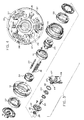
- Fig. 2 shows the inner faces of hubs 24 and 25 are provided with facing recesses 34 and 35, respectfully, and a plurality of clutch members or shoes 36 are shiftable between recesses 34 and 35.
- Fig. 2 shows the clutch shoes 36 being located within recess 34 in hub 24.
- each shoe 36 is provided with an arcuate or curved outer surface 37 which is adapted to engage the inner surface of the respective pulley 18 and 19.
- Clutch shoes 36 are biased to an inner position by extension springs 38 which connect the adjacent edges of the shoes. As the motor speed increases shoes 36 will be moved outwardly under centrifugal force, causing the outer surfaces 37 to engage the inner surface of the respective pulley 18 and 19 to provide a driving connection between the drive shaft 16 and the pulley.
- a plurality of operating rods 39 extend through radial slot 40 in each shoe.
- the radial slot 40 permits the shoes 36 to move radially relative to the respective rod.
- Snap rings 41 are mounted within grooves in each rod 39 and are located on either side of the shoe 36.
- Rods 39 rotate with hubs 24 and drive shaft 16 and are mounted for sliding movement within aligned openings in hubs 24 and 25.
- the corresponding ends of rods 39 are connected to an annular disc 42, which is located outboard of hub 25.
- Disc 42 is provided with an inner annular flange 43, which is located within a recess in the outer face of hub 25.
- Flange 43 is connected to a non-rotatable pin 44 through a bearing 45.
- Bearing 45 is mounted against a shoulder in flange 43 and retained against the shoulder by a snap ring 46. As the pin 44 does not rotate, the bearing 45 enables disc 42, rods 39 and hubs 24 and 25 to rotate relative to the pin.
- the outer end of pin 44 carries a pair of discs 47 which straddle the upper end of an arm 48.
- Arm 48 is mounted for sliding movement on a guide rod 49 that extends outwardly from the engine and the lower end of the arm is connected to an operating rod 50.
- the operating rod 50 can be connected in a conventional manner through a cable system to a lever on the handle 7 so that the operator, by moving the lever, can move the arm 48 along with the rods 39 to shift clutch 17 within the recesses in hubs 24 and 25.
- the use of a single belt 20 to drive the eccentric shafts 8 and 9 provides distinct advantages over the use of dual belts. Specifically, the belt tensioning operation is simplified and tension on the belt can readily be adjusted by moving the vertical position of the engine relative to the compactor plate. As a further advantage, belt 20 is wrapped around the pulleys 21 and 22 through an arc of more than 180°, providing a more effective drive to the eccentric shafts. With this increased wrap, a smaller width belt can be utilized and as less heat will be generated in a smaller width belt than in a wider belt, the belt service life is increased.
Landscapes
- Engineering & Computer Science (AREA)
- Structural Engineering (AREA)
- Civil Engineering (AREA)
- Life Sciences & Earth Sciences (AREA)
- Environmental & Geological Engineering (AREA)
- Soil Sciences (AREA)
- General Life Sciences & Earth Sciences (AREA)
- Mining & Mineral Resources (AREA)
- Paleontology (AREA)
- Agronomy & Crop Science (AREA)
- General Engineering & Computer Science (AREA)
- Architecture (AREA)
- Road Paving Machines (AREA)
- One-Way And Automatic Clutches, And Combinations Of Different Clutches (AREA)
- Investigation Of Foundation Soil And Reinforcement Of Foundation Soil By Compacting Or Drainage (AREA)
Abstract
Description
Claims (6)
- A vibratory compactor, comprising a frame (2), a compaction plate (4) mounted on the frame and adapted to engage material to be compacted, drive means (12) mounted on the frame and including a drive shaft (16), a pair of eccentric shafts (8,9) mounted for rotation on the frame, a first support member (21) connected to a first of said eccentric shafts (8), a second support member connected to a second of said eccentric shafts (9), characterized in that a third support member (18) and a fourth support member (19) are mounted on the drive shaft, a single endless flexible connecting member (20) is operably connected to the first, second, third and fourth support members and is constructed and arranged so that both eccentric shafts rotate simultaneously in the same direction, and clutch means (17) for selectively interconnecting said drive shaft (16) with said third (18) and fourth (19) support members.
- The compactor of claim 1, wherein each eccentric shaft (8,9) includes a weight (11) mounted eccentrically on the axis of said shaft, said eccentric weights being in the same phase relation on the respective eccentric shafts.
- The compactor of claim 1, wherein said support members (18,19,21,22) comprise pulleys and said flexible connecting member (20) is a belt.
- The compactor of claim 1, wherein said clutch means (17) comprises a clutch member (36) mounted for axial movement on said drive shaft from a first position where said clutch member is engageable with said third support member (18) to a second position where said clutch member is engageable with said fourth support member (19).
- The compactor of claim 4, wherein said clutch member (36) is movable radially when in each of said positions by centrifugal force on rotation of said drive shaft (16) from an inner disengaged position to an outer engaged position where said clutch member will engage the respective third or fourth support member.
- The compactor of claim 5, and including biasing means (38) for biasing said clutch member (36) inwardly toward said drive shaft.
Applications Claiming Priority (3)
| Application Number | Priority Date | Filing Date | Title |
|---|---|---|---|
| US28318 | 1993-03-09 | ||
| US08/028,318 US5387052A (en) | 1993-03-09 | 1993-03-09 | Drive mechanism for a vibratory compactor |
| PCT/US1994/002223 WO1994020693A2 (en) | 1993-03-09 | 1994-03-01 | Drive mechanism for a vibratory compactor |
Publications (2)
| Publication Number | Publication Date |
|---|---|
| EP0688380A1 EP0688380A1 (en) | 1995-12-27 |
| EP0688380B1 true EP0688380B1 (en) | 1999-01-27 |
Family
ID=21842774
Family Applications (1)
| Application Number | Title | Priority Date | Filing Date |
|---|---|---|---|
| EP94909842A Expired - Lifetime EP0688380B1 (en) | 1993-03-09 | 1994-03-01 | Drive mechanism for a vibratory compactor |
Country Status (6)
| Country | Link |
|---|---|
| US (1) | US5387052A (en) |
| EP (1) | EP0688380B1 (en) |
| JP (1) | JP2928387B2 (en) |
| DE (1) | DE69416301D1 (en) |
| MX (1) | MX9401695A (en) |
| WO (1) | WO1994020693A2 (en) |
Cited By (1)
| Publication number | Priority date | Publication date | Assignee | Title |
|---|---|---|---|---|
| DE102017105117A1 (en) | 2017-03-10 | 2018-09-13 | Wacker Neuson Produktion GmbH & Co. KG | Soil compacting device with compensating coupling |
Families Citing this family (23)
| Publication number | Priority date | Publication date | Assignee | Title |
|---|---|---|---|---|
| US5439314A (en) * | 1994-01-03 | 1995-08-08 | Wadensten; Theodore S. | Reversible self-propelled plate compactor |
| US5934825A (en) * | 1997-01-28 | 1999-08-10 | Wacker Corporation | Vibratory plate machine |
| USD393864S (en) | 1997-01-28 | 1998-04-28 | Wacker Corporation | Vibratory asphalt plate |
| DE29805792U1 (en) * | 1998-03-30 | 1998-06-25 | Dietl, Matthias A., 80799 München | Infinitely variable conical pulley belt transmission |
| US6367345B1 (en) * | 1999-10-21 | 2002-04-09 | Traxxas Corporation | Forward/reverse transmission for scale model vehicle |
| US6609576B1 (en) * | 2000-11-28 | 2003-08-26 | Melvin Hubbard | Method and apparatus for vibratory kinetic energy generation and applications thereof |
| TW526120B (en) * | 2001-12-20 | 2003-04-01 | Chin Fong Machine Ind Co Ltd | Program-controllable torque magnifying mechanism |
| US7165469B2 (en) * | 2003-04-10 | 2007-01-23 | M-B-W Inc. | Shift rod piston seal arrangement for a vibratory plate compactor |
| DE202005002235U1 (en) * | 2005-02-11 | 2006-06-22 | Bomag Gmbh | Snow compactor and track device |
| US7354221B2 (en) * | 2005-02-28 | 2008-04-08 | Caterpillar Inc. | Self-propelled plate compactor having linear excitation |
| US7591254B2 (en) * | 2007-03-28 | 2009-09-22 | Billy Machner | Supercharger control system |
| DE102010008244A1 (en) * | 2010-02-17 | 2011-08-18 | Andreas Stihl AG & Co. KG, 71336 | Centrifugally operated coupling device |
| US9677240B2 (en) | 2012-09-05 | 2017-06-13 | M-B-W Inc. | Single direction vibratory plate |
| WO2016029317A1 (en) * | 2014-08-28 | 2016-03-03 | Sorg Daniel | Vibratory plate compactor with grading means |
| SE541862C2 (en) * | 2016-04-29 | 2019-12-27 | Construction Tools Pc Ab | Rig mounted compactor |
| US20170009407A1 (en) * | 2016-09-26 | 2017-01-12 | Caterpillar Inc. | Vibratory plate compactor |
| AU2020380962B2 (en) | 2019-11-08 | 2023-11-02 | Milwaukee Electric Tool Corporation | Motor control for gas engine replacement device |
| WO2021092438A1 (en) * | 2019-11-08 | 2021-05-14 | Milwaukee Electric Tool Corporation | Bi-directional motor for gas engine replacement device |
| JP7803859B2 (en) | 2019-12-10 | 2026-01-21 | ミルウォーキー エレクトリック ツール コーポレイション | Motor Control for Gas Engine Alternatives Based on Battery Pack Configuration Data |
| US11689081B2 (en) | 2019-12-20 | 2023-06-27 | Milwaukee Electric Tool Corporation | Gas engine replacement electronics modularity for feature expansion |
| CN114868325B (en) | 2019-12-23 | 2026-01-27 | 米沃奇电动工具公司 | Remotely controlled power unit |
| CN219436806U (en) | 2020-04-10 | 2023-07-28 | 米沃奇电动工具公司 | Adapter and system for configuring device settings of a gas engine replacement device |
| WO2021257433A1 (en) | 2020-06-17 | 2021-12-23 | Milwaukee Electric Tool Corporation | Motor control for gas engine replacement device |
Family Cites Families (21)
| Publication number | Priority date | Publication date | Assignee | Title |
|---|---|---|---|---|
| US2908206A (en) * | 1956-09-27 | 1959-10-13 | Robert C Melanson | Multiple tamping machine |
| US3048089A (en) * | 1958-09-12 | 1962-08-07 | Bomag Bopparder Machinenbau Ge | Land roller for rolling road surfaces and the like |
| US3109326A (en) * | 1960-12-12 | 1963-11-05 | Maurice O Holtan | Change speed power transmission |
| DE1634246A1 (en) * | 1965-06-08 | 1970-07-16 | Bopparder Maschb Gmbh | Vibrating roller |
| DE1634492A1 (en) * | 1967-05-03 | 1970-06-25 | Joachim Mozdzanowski | Record rattle |
| US3603224A (en) * | 1969-02-18 | 1971-09-07 | Ingersoll Rand Co | Plate-type vibrator compactor |
| DE2001987A1 (en) * | 1970-01-17 | 1971-07-29 | Benno Kaltenegger | Soil compacting device |
| DE2011420A1 (en) * | 1970-03-11 | 1971-09-23 | Maschinenfabrik Fahr Ag, 7702 Gottmadingen | Direction of rotation controllable gear |
| US3753621A (en) * | 1971-04-16 | 1973-08-21 | East Moline Metal Prod Co | Concrete-working machine with walking vibrators |
| FR2214788B3 (en) * | 1973-01-23 | 1976-01-30 | Couthon Mat Genie Civil Roulea | |
| US4031761A (en) * | 1975-02-20 | 1977-06-28 | Dayco Corporation | Engine power take-off system with single belt drive |
| US4061000A (en) * | 1976-06-21 | 1977-12-06 | General Motors Corporation | Belt drive arrangement for agitator washer mechanism |
| US4138837A (en) * | 1976-10-26 | 1979-02-13 | Deere & Company | Variable speed reversible drive for a harvesting apparatus |
| US4289042A (en) * | 1978-04-24 | 1981-09-15 | Fmc Corporation | Vibrator with eccentric weights |
| US4237983A (en) * | 1978-12-07 | 1980-12-09 | Allen Douglas E | Combination tiller and cultivator and reversible drive assembly therefor |
| US4499779A (en) * | 1982-06-07 | 1985-02-19 | M-B-W Inc. | Vibratory compactor |
| GB2155871B (en) * | 1984-03-20 | 1987-10-21 | Stothert & Pitt Plc | Vibrator/roller with disengageable drive arrangement |
| US4643611A (en) * | 1985-04-08 | 1987-02-17 | Wacker Corporation | Vibratory compactor having improved cast base |
| US5125488A (en) * | 1988-06-27 | 1992-06-30 | Rover Mowers Limited | Drive assembly having dual neutrality control |
| US5064053A (en) * | 1990-10-24 | 1991-11-12 | Carrier Vibrating Equipment, Inc. | Vibratory drive system for a vibratory conveyor apparatus and a conveyor apparatus having same |
| US5149225A (en) * | 1991-03-13 | 1992-09-22 | M-B-W Inc. | Reversible drive for a vibratory compactor |
-
1993
- 1993-03-09 US US08/028,318 patent/US5387052A/en not_active Expired - Fee Related
-
1994
- 1994-03-01 JP JP6520118A patent/JP2928387B2/en not_active Expired - Lifetime
- 1994-03-01 DE DE69416301T patent/DE69416301D1/en not_active Expired - Lifetime
- 1994-03-01 EP EP94909842A patent/EP0688380B1/en not_active Expired - Lifetime
- 1994-03-01 WO PCT/US1994/002223 patent/WO1994020693A2/en not_active Ceased
- 1994-03-08 MX MX9401695A patent/MX9401695A/en not_active IP Right Cessation
Cited By (1)
| Publication number | Priority date | Publication date | Assignee | Title |
|---|---|---|---|---|
| DE102017105117A1 (en) | 2017-03-10 | 2018-09-13 | Wacker Neuson Produktion GmbH & Co. KG | Soil compacting device with compensating coupling |
Also Published As
| Publication number | Publication date |
|---|---|
| DE69416301D1 (en) | 1999-03-11 |
| WO1994020693A3 (en) | 1994-12-22 |
| MX9401695A (en) | 1995-01-31 |
| JPH08507578A (en) | 1996-08-13 |
| WO1994020693A2 (en) | 1994-09-15 |
| US5387052A (en) | 1995-02-07 |
| JP2928387B2 (en) | 1999-08-03 |
| EP0688380A1 (en) | 1995-12-27 |
Similar Documents
| Publication | Publication Date | Title |
|---|---|---|
| US5387052A (en) | Drive mechanism for a vibratory compactor | |
| US5149225A (en) | Reversible drive for a vibratory compactor | |
| WO1994020693B1 (en) | Drive mechanism for a vibratory compactor | |
| US7465244B2 (en) | Utility machinery and associated control arrangements | |
| US4738651A (en) | Steplessly adjustable belt-type transmission | |
| CA2488359C (en) | Portable roller-type compactor apparatus having a combined means for the vibrating and the reversible propelling thereof | |
| US8052556B2 (en) | Apparatuses and methods for controlling a variable speed transmission | |
| GB1437450A (en) | Self-propelled ridable lawnmowers | |
| RU188664U1 (en) | CHAIN REDUCER WITH REVERSE | |
| US5601000A (en) | Gearbox with incorporated clutch for self-propelled machines | |
| US3706363A (en) | Lawn mower friction drive with slip clutch | |
| US5320448A (en) | Drive mechanism for a vibratory compactor | |
| US4529394A (en) | Transmission ratio variators | |
| US5209331A (en) | Clutch construction | |
| JP3000586B2 (en) | Transmission for vehicles | |
| US6951523B1 (en) | Mechanical variable reversible transmission | |
| US4465037A (en) | Shock absorbing cam shaft driving system | |
| US2823560A (en) | Controllable multiple driving mechanism | |
| US7235026B2 (en) | Utility machinery and associated control arrangements | |
| JPH0135973Y2 (en) | ||
| JPH0730823B2 (en) | Belt type continuously variable transmission | |
| US4161890A (en) | Friction drive contact zone | |
| US4068378A (en) | Portable chain saw | |
| SU1698553A1 (en) | Infinitely-variable v-belt transmission | |
| RU2050096C1 (en) | Power mower |
Legal Events
| Date | Code | Title | Description |
|---|---|---|---|
| PUAI | Public reference made under article 153(3) epc to a published international application that has entered the european phase |
Free format text: ORIGINAL CODE: 0009012 |
|
| 17P | Request for examination filed |
Effective date: 19950922 |
|
| AK | Designated contracting states |
Kind code of ref document: A1 Designated state(s): DE ES FR GB IT SE |
|
| 17Q | First examination report despatched |
Effective date: 19970603 |
|
| GRAG | Despatch of communication of intention to grant |
Free format text: ORIGINAL CODE: EPIDOS AGRA |
|
| GRAG | Despatch of communication of intention to grant |
Free format text: ORIGINAL CODE: EPIDOS AGRA |
|
| GRAH | Despatch of communication of intention to grant a patent |
Free format text: ORIGINAL CODE: EPIDOS IGRA |
|
| GRAH | Despatch of communication of intention to grant a patent |
Free format text: ORIGINAL CODE: EPIDOS IGRA |
|
| GRAA | (expected) grant |
Free format text: ORIGINAL CODE: 0009210 |
|
| AK | Designated contracting states |
Kind code of ref document: B1 Designated state(s): DE ES FR GB IT SE |
|
| PG25 | Lapsed in a contracting state [announced via postgrant information from national office to epo] |
Ref country code: SE Free format text: THE PATENT HAS BEEN ANNULLED BY A DECISION OF A NATIONAL AUTHORITY Effective date: 19990127 Ref country code: IT Free format text: LAPSE BECAUSE OF FAILURE TO SUBMIT A TRANSLATION OF THE DESCRIPTION OR TO PAY THE FEE WITHIN THE PRESCRIBED TIME-LIMIT;WARNING: LAPSES OF ITALIAN PATENTS WITH EFFECTIVE DATE BEFORE 2007 MAY HAVE OCCURRED AT ANY TIME BEFORE 2007. THE CORRECT EFFECTIVE DATE MAY BE DIFFERENT FROM THE ONE RECORDED. Effective date: 19990127 Ref country code: FR Free format text: LAPSE BECAUSE OF FAILURE TO SUBMIT A TRANSLATION OF THE DESCRIPTION OR TO PAY THE FEE WITHIN THE PRESCRIBED TIME-LIMIT Effective date: 19990127 Ref country code: ES Free format text: THE PATENT HAS BEEN ANNULLED BY A DECISION OF A NATIONAL AUTHORITY Effective date: 19990127 |
|
| PGFP | Annual fee paid to national office [announced via postgrant information from national office to epo] |
Ref country code: GB Payment date: 19990304 Year of fee payment: 6 |
|
| REF | Corresponds to: |
Ref document number: 69416301 Country of ref document: DE Date of ref document: 19990311 |
|
| PG25 | Lapsed in a contracting state [announced via postgrant information from national office to epo] |
Ref country code: DE Free format text: LAPSE BECAUSE OF FAILURE TO SUBMIT A TRANSLATION OF THE DESCRIPTION OR TO PAY THE FEE WITHIN THE PRESCRIBED TIME-LIMIT Effective date: 19990428 |
|
| EN | Fr: translation not filed | ||
| PLBE | No opposition filed within time limit |
Free format text: ORIGINAL CODE: 0009261 |
|
| STAA | Information on the status of an ep patent application or granted ep patent |
Free format text: STATUS: NO OPPOSITION FILED WITHIN TIME LIMIT |
|
| 26N | No opposition filed | ||
| PG25 | Lapsed in a contracting state [announced via postgrant information from national office to epo] |
Ref country code: GB Free format text: LAPSE BECAUSE OF NON-PAYMENT OF DUE FEES Effective date: 20000301 |
|
| GBPC | Gb: european patent ceased through non-payment of renewal fee |
Effective date: 20000301 |