EP0688258B1 - Locking pliers with axial clamping action - Google Patents
Locking pliers with axial clamping action Download PDFInfo
- Publication number
- EP0688258B1 EP0688258B1 EP95906811A EP95906811A EP0688258B1 EP 0688258 B1 EP0688258 B1 EP 0688258B1 EP 95906811 A EP95906811 A EP 95906811A EP 95906811 A EP95906811 A EP 95906811A EP 0688258 B1 EP0688258 B1 EP 0688258B1
- Authority
- EP
- European Patent Office
- Prior art keywords
- movable
- fixed
- extension
- jaw
- movable jaw
- Prior art date
- Legal status (The legal status is an assumption and is not a legal conclusion. Google has not performed a legal analysis and makes no representation as to the accuracy of the status listed.)
- Expired - Lifetime
Links
Images


Classifications
-
- B—PERFORMING OPERATIONS; TRANSPORTING
- B25—HAND TOOLS; PORTABLE POWER-DRIVEN TOOLS; MANIPULATORS
- B25B—TOOLS OR BENCH DEVICES NOT OTHERWISE PROVIDED FOR, FOR FASTENING, CONNECTING, DISENGAGING, OR HOLDING
- B25B7/00—Pliers; Other hand-held gripping tools with jaws on pivoted limbs; Details applicable generally to pivoted-limb hand tools
- B25B7/06—Joints
- B25B7/10—Joints with adjustable fulcrum
-
- B—PERFORMING OPERATIONS; TRANSPORTING
- B25—HAND TOOLS; PORTABLE POWER-DRIVEN TOOLS; MANIPULATORS
- B25B—TOOLS OR BENCH DEVICES NOT OTHERWISE PROVIDED FOR, FOR FASTENING, CONNECTING, DISENGAGING, OR HOLDING
- B25B7/00—Pliers; Other hand-held gripping tools with jaws on pivoted limbs; Details applicable generally to pivoted-limb hand tools
- B25B7/02—Jaws
-
- B—PERFORMING OPERATIONS; TRANSPORTING
- B25—HAND TOOLS; PORTABLE POWER-DRIVEN TOOLS; MANIPULATORS
- B25B—TOOLS OR BENCH DEVICES NOT OTHERWISE PROVIDED FOR, FOR FASTENING, CONNECTING, DISENGAGING, OR HOLDING
- B25B7/00—Pliers; Other hand-held gripping tools with jaws on pivoted limbs; Details applicable generally to pivoted-limb hand tools
- B25B7/12—Pliers; Other hand-held gripping tools with jaws on pivoted limbs; Details applicable generally to pivoted-limb hand tools involving special transmission means between the handles and the jaws, e.g. toggle levers, gears
- B25B7/123—Pliers; Other hand-held gripping tools with jaws on pivoted limbs; Details applicable generally to pivoted-limb hand tools involving special transmission means between the handles and the jaws, e.g. toggle levers, gears with self-locking toggle levers
-
- Y—GENERAL TAGGING OF NEW TECHNOLOGICAL DEVELOPMENTS; GENERAL TAGGING OF CROSS-SECTIONAL TECHNOLOGIES SPANNING OVER SEVERAL SECTIONS OF THE IPC; TECHNICAL SUBJECTS COVERED BY FORMER USPC CROSS-REFERENCE ART COLLECTIONS [XRACs] AND DIGESTS
- Y10—TECHNICAL SUBJECTS COVERED BY FORMER USPC
- Y10T—TECHNICAL SUBJECTS COVERED BY FORMER US CLASSIFICATION
- Y10T29/00—Metal working
- Y10T29/53—Means to assemble or disassemble
- Y10T29/53796—Puller or pusher means, contained force multiplying operator
- Y10T29/53896—Puller or pusher means, contained force multiplying operator having lever operator
- Y10T29/539—Plier type means
Definitions
- the present invention relates to locking pliers of the type as described in the preambles of claims 1 and 6.
- Locking pliers of this type are described in US-A-3210070.
- the pliers have a longitudinally extending body and a movable jaw pivotably connected to the body. Opposite the movable jaw, a fixed extension is secured to the body.
- the body further has a channel member extending transversely to the longitudinal axis of the body and receiving a movable extension for movement transverse to the longitudinal axis of the body.
- the movable extension rests with its free end on the upper surface of the movable jaw. When the movable jaw is closed, the upper surface pushes the movable extension into the clamping position, while the upper surface of the movable jaw translates with respect to the free end of the movable extension.
- US-A-2519630 describes a plier wrench having a fixed jaw fixedly connected to a longitudinally extending body, and a movable jaw connected to the body via a hinge.
- the jaws are adapted to clamp the workpiece therebetween.
- the hinge includes an elongated slot provided at the movable jaw, and a hinge pin fixedly connected to the body.
- the slot extends transverse to the longitudinal extension of the body for allowing the movable jaw to be oriented parallel to the fixed jaw over a distance corresponding to the length of the elongated slot.
- axial clamps Other locking pliers are known in which fixed and movable clamping elements approach one another in an axial direction as the pliers are closed. Such pliers in the past have been referred to as axial clamps.
- the axial clamps known to the inventors have provided an axially oriented shaft on the body of the pliers and a sleeve on the movable clamping element. As the pliers are closed the sleeve is moved axially along the shaft to cause the fixed and movable clamping elements to approach one another.
- This prior art arrangement relies on a telescoping or sliding action between the fixed and movable clamping elements of the pliers. This is in contrast to a conventional locking pliers such as that shown in US-A-4,541,312, in which the movable jaw is pivotably mounted with respect to the body to pivot the movable clamping element toward the fixed clamping element in a circumferential rather than an axial direction. It would be advantageous if an axial clamp could be formed in such a way as to eliminate the need for the telescoping sleeve of the prior art.
- locking pliers are provided having the features of claim 1 or claim 6.
- the movable extension can either be fixedly or pivotably mounted to the movable jaw.
- either the body or the movable jaw defines an elongated slot that receives the hinge pin, and the slot allows the movable jaw both to pivot and to translate as the movable jaw is closed.
- the movable jaw extension is biased into sliding contact with the fixed extension by a closing spring as the movable jaw is closed.
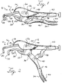
- FIGS. 1 and 2 show two views of a pair of locking pliers 10 which incorporates a first preferred embodiment of this invention.
- the locking pliers 10 include a body 12 which terminates at one end in a fixed jaw 14.
- a fixed extension 16 is rigidly secured to the fixed jaw 14, as for example by welding.
- This fixed extension 16 is generally L-shaped in side view and generally rectangular in top view, and it includes first and second fixed segments 18, 20.
- the first fixed segment 18 is secured to the fixed jaw 14, and the second fixed segment 20 extends out of the plane of the first fixed segment to define a fixed clamping element.
- the locking pliers 10 also include a movable jaw 22 that is mounted for pivotal movement with respect to the body 12 about a hinge pin 26 that is received in an elongated slot 24 defined by movable jaw 22.
- the movable jaw 22 pivots with respect to the body 12 about the hinge pin 26, and the movable jaw 22 translates with respect to the body 12 as the elongated slot 24 moves with respect to the hinge pin 26.
- the movable jaw 22 includes a movable extension 28 which is generally L-shaped in side view and generally rectangular in top view, and it is made up of first and second movable segments 30, 32.
- the first movable segment 30 is rigidly secured to the movable jaw 22, as for example by welding.
- the second movable segment 32 extends as shown in Figure 1 to define a movable clamping element.
- An operating lever 34 is pivotably mounted to the movable jaw 22 by a pivot pin 36.
- An over-center locking linkage comprising a stub shaft 38 is pivotably mounted to the operating lever 34 by a pivot pin 40.
- the end of the stub shaft 38 remote from the pivot pin 40 bears on an adjustable stop 42 which in this embodiment is the free end of a screw adjust element that is threaded in place on the body 12.
- the longitudinal axis of the adjustable stop 42 is generally aligned with the longitudinal axis of the body 12, and in the closed position the elongated slot 24 is oriented to extend generally parallel to this axial direction.
- a release lever 44 is pivotably mounted to the operating lever 38 by a pivot pin 46, and the release lever 44 bears on the stub shaft 38 to release the over-center locking linkage in the conventional manner.
- An opening spring 48 is mounted between the movable jaw 22 and the body 12 to bias the movable jaw 22 in the counter-clockwise direction as shown in Figure 1 to open the pliers 10.
- the operation of the over-center locking linkage, the operating level 34, the adjustable stop 42, the release lever 44, the opening spring 48, and the associated parts of the body 12, are all conventional, and therefore do not require further discussion. See, for example the pliers described in US-A-4,541,312, which clarifies that the body is U-shaped in cross-section, and that the movable jaw, opening spring, stub shaft, and adjustable stop are all mounted within the body.
- Figure 2 shows the locking pliers 10 in the opened position. Note that the operating lever 34 has been moved away from the body 12, and that the opening spring 48 has rotated the movable jaw 22 in the counter-clockwise direction.
- the operating lever 34 In order to close the locking pliers 10 from the opened position of Figure 2, the operating lever 34 is moved toward the body 12. This action initially rotates the movable jaw 22 in the clockwise direction until the movable extension 28 comes into sliding contact with the fixed extension 16. Further movement of the operating lever 34 causes the movable extension 28 to slide along the longitudinal direction of the fixed extension 16 and to move the movable clamping element formed by the second movable segment 32 toward the fixed clamping element formed by the second fixed segment 20. Note that the clamping action is generally axial, with the movable clamping element moving in a direction substantially parallel to the axial direction defined by the body 12. This axial movement of the movable clamping element with respect to the fixed clamping element is made possible by the elongated slot 24 which slides in translation with respect to the hinge pin 26 as the movable jaw 22 is closed.
- Figures 3 and 4 provide two views of a pair of locking pliers 10' which incorporates a second preferred embodiment of this invention.
- the body 12, fixed jaw 14, fixed extension 16, operating lever 34, stub shaft 38, adjustable stop 42, release lever 44 and opening spring 48 are all identical in both embodiments, and therefore no further explanation is required.
- the locking pliers 10' differ from the locking pliers 10 primarily in the construction of the movable jaw and the movable extension.
- the movable jaw 22' is pivoted about the hinge pin 26' in a manner that prevents longitudinal sliding movement between the movable jaw 22' and the body 12.
- the movable extension 28' as before comprises a first segment 30' and a second segment 32'.
- the movable extension 28' is pivotably mounted to the movable jaw 22' by a pivot pin 29'.
- a closing spring 31' is secured between the movable extension 28' and the body 12. This closing spring 31' biases the movable extension 28' toward the fixed extension 16.
- FIG. 4 shows the locking pliers 10' in an opened position.
- the closing spring 31' maintains the movable extension 28' in sliding contact with the fixed extension 16 along the longitudinal direction thereof.
- the movable jaw 22' is pivoted in the clockwise direction about the hinge pin 26'.
- the movable extension 28' pivots as necessary about the pivot pin 29' to maintain the movable extension 28' in sliding contact with the fixed extension 16 as the movable jaw 22' closes.
- the second movable segment 32' which forms the movable clamping element moves in a generally axial direction (generally aligned with the longitudinal axis defined by the body 12) as the movable clamping element moves to the closed position.
- the adjustable stop 42 can be rotated to adjust its axial position in the body 12. In this way the locking pliers 10, 10' can be adjusted to provide the desired axial separation between the opposed clamping elements when the locking pliers are fully closed.
- FIGs 5 and 6 show two views of a third preferred embodiment 10'' of this invention.
- This third preferred embodiment 10'' is similar to the first preferred embodiment 10 described above, except that the extensions 16'', 28'' are bent as shown in Figures 5 and 6.
- This arrangement allows the operating lever 34 to be spaced a greater distance from the workpiece W to facilitate operation of the pliers 10''.
- the sliding direction in which the segment 32'' approaches the segment 20'' is angled with respect to the longitudinal axis of the body 12'' by an angle equal to the bend in the extensions 16'', 28''.
- the locking pliers 10, 10', 10'' are useful in many applications where it is desired to have the opposed clamping elements approach one another in an axial manner. These pliers 10, 10', 10'' can be used for example in welding operations, where it is desired to secure two pieces of sheet metal together for welding.
- the right angle configuration of the illustrated extensions allows the locking pliers 10, 10', 10'' to be used in situations where the locking pliers are best positioned out of the plane of the sheet metal being welded.
- the fixed and movable extensions can be provided with a horseshoe shape if desired to provide two clamping regions spaced from one another along a direction transverse to the axial direction described above.
- the included angle between the first and second segments 18, 20; 30, 32 can differ from the 90° angle shown, and can be 120°-135° for example. It is therefore intended that the foregoing detailed description be regarded as illustrative rather than limiting, and that it be understood that it is the following claims which define the scope of this invention.
Landscapes
- Engineering & Computer Science (AREA)
- Mechanical Engineering (AREA)
- Gripping Jigs, Holding Jigs, And Positioning Jigs (AREA)
- Mutual Connection Of Rods And Tubes (AREA)
- Orthopedics, Nursing, And Contraception (AREA)
- Manipulator (AREA)
- Food-Manufacturing Devices (AREA)
- Surgical Instruments (AREA)
Abstract
Description
Claims (9)
- A locking pliers (10,10'') comprising:a body (12) comprising a fixed jaw (14) fixedly positioned with respect to the body (12), said fixed jaw (14) comprising a fixed extension (16,16'') which in turn comprises a fixed clamping element (20,20'');a movable jaw (22) mounted to the body (12) to pivot about a hinge pin (26), said movable jaw (22) comprising a movable extension (28,28'') which in turn comprises a movable clamping element (32,32''),an operating lever (34) pivotably mounted to the movable jaw (22), and adapted to pivot the movable jaw (22) for closing the pliers (10,10'');an over-center locking linkage (38,40) coupled between the operating lever (34) and the body (12) to hold the operating lever (34) and the movable jaw (22) closed, with the fixed and movable clamping elements (20,32,20'',32'') in opposed, clamping relationship;said movable jaw (22) shaped and disposed such that the movable extension (28,28'') slides along the fixed extension (16) as the pliers (10,10'') are closed with the operating lever (34), thereby providing a sliding clamping action in the longitudinal direction of said fixed extension (16,16'');
characterised in thatsaid movable extension (28,28'') is mounted in place on the movable jaw (22) to prevent translation between the movable jaw (22) and the movable extension (28,28'');
wherein the movable extension (28,28'') is fixedly positioned with respect to the movable jaw (22), one of the body (12) and the movable jaw (22) defines an elongated slot (24), and the hinge pin (26) passes through the slot (24) such that during closing, the movable jaw (22) translates with respect to the body (12) as the slot (24) and the hinge pin (26) move with respect to each other, said slot (24) being oriented such that the movable extension (28,28'') slides along the fixed extension (16) as the pliers (10,10'') are closed with the operating lever (34). - The pliers of claim 1 wherein the movable jaw (22) defines the elongated slot (24).
- The pliers of claim 1 or 2, further comprising an opening spring (48) mounted between the movable jaw (22) and the body (12) to bias the movable jaw open.
- The pliers of any one of claims 1 to 3, wherein:said movable jaw (22) defines said elongated slot (24), said body (12) mounts the hinge pin (26), and said hinge pin (26) is received in the slot (24);an opening spring (48) is coupled between the movable jaw (22) and the body (12) to bias the movable jaw (22) open with the hinge pin (26) positioned at a first end of the slot (24);said slot (24) being positioned such that movement of the operating lever (34) to close the movable jaw (22) moves the movable jaw (22) with respect to the hinge pin (26) to cause the movable extension (28,28'') to slide along the fixed extension (16,16'') as the slot (24) translates with respect to the hinge pin (26) and the movable clamping element (32,32'') approaches the fixed clamping element (20,20'').
- The pliers of any one of claim 1 to 4, wherein the body (12) defines an axial direction extending along a length of the body (12), wherein the slot (24) defines a length direction, and wherein the length direction of the slot (24) is generally parallel to the axial direction.
- A locking pliers (10,) comprising:a body (12) comprising a fixed jaw (14) fixedly positioned with respect to the body (12), said fixed jaw (14) comprising a fixed extension (16) which in turn comprises a fixed clamping element (20);a movable jaw (22') mounted to the body (12) to pivot about a hinge pin (26'), said movable jaw (22') comprising a movable extension (28') which in turn comprises a movable clamping element (32'),an operating lever (34) pivotably mounted to the movable jaw (22,22'), and adapted to pivot the movable jaw (22') for closing the pliers (10');an over-center locking linkage (38,40) coupled between the operating lever (34) and the body (12) to hold the operating lever (34) and the movable jaw (22') closed, with the fixed and movable clamping elements (20,32') in opposed clamping relationship;said movable jaw (22') shaped and disposed such that the movable extension (28') slides along the fixed extension (16) as the pliers (10') are closed with the operating lever (34), thereby providing a sliding clamping action in the longitudinal direction of said fixed extension (16);
characterised in thatsaid movable extension (28') is mounted in place on the movable jaw (22') to prevent translation between the movable jaw (22') and the movable extension (28'); wherein said movable extension (28') is pivotably mounted to said movable jaw (22') by a pivot pin (29') disposed between the hinge pin (26') that couples the movable jaw (22') to the body (12) and a further pivot pin (36) that couples the movable jaw (22') to the operating lever (34); anda closing spring (31') is coupled to the movable extension (28') to bias the movable extension (28') into contact with the fixed extension (16) as the pliers (10') are closed such that movement of the movable jaw (22') about the hinge pin (26') causes the movable extension (28') to slide along the fixed extension (16). - The pliers of any one of claims 1 to 6 wherein the fixed extension (16,16'') comprises a first fixed segment (18,18'') secured to the fixed jaw (14) and a second fixed segment (20,20'') secured to the first fixed segment (18,18'') at a point remote from the fixed jaw (14), wherein the movable extension (28,28',28'') comprises a first movable segment (30,30',30'') secured to the movable jaw (22,22') and a second movable segment (32,32',32'') secured to the first movable segment (30,30',30'') at a point remote from the movable jaw (22,22'), wherein the fixed clamping element (20,20') comprises the second fixed segment, and wherein the movable clamping element (32,32',32'') comprises the second movable segment.
- The pliers of claim 7, wherein the fixed and movable extensions (16,16'',28,28',28'') are generally L-shaped in side view, with the first fixed segment (18,18'') oriented generally parallel to the first movable segment (30,30',30'') and the second fixed segment (20,20'') oriented generally parallel to the second movable segment (32,32',32'') when the movable jaw (22,22') is closed.
- The pliers of any one of claims 1 to 8, wherein the fixed and movable extension (16'',28'') are bent to offset the clamping elements (20'',32'') with respect to the body (12) when the movable jaw is closed.
Applications Claiming Priority (3)
| Application Number | Priority Date | Filing Date | Title |
|---|---|---|---|
| US179744 | 1994-01-11 | ||
| US08/179,744 US5456144A (en) | 1994-01-11 | 1994-01-11 | Locking pliers with axial clamping action |
| PCT/US1995/000388 WO1995018699A1 (en) | 1994-01-11 | 1995-01-10 | Locking pliers with axial clamping action |
Publications (3)
| Publication Number | Publication Date |
|---|---|
| EP0688258A1 EP0688258A1 (en) | 1995-12-27 |
| EP0688258A4 EP0688258A4 (en) | 1996-10-23 |
| EP0688258B1 true EP0688258B1 (en) | 1999-03-03 |
Family
ID=22657814
Family Applications (1)
| Application Number | Title | Priority Date | Filing Date |
|---|---|---|---|
| EP95906811A Expired - Lifetime EP0688258B1 (en) | 1994-01-11 | 1995-01-10 | Locking pliers with axial clamping action |
Country Status (23)
| Country | Link |
|---|---|
| US (1) | US5456144A (en) |
| EP (1) | EP0688258B1 (en) |
| JP (1) | JP3093592B2 (en) |
| KR (1) | KR100378666B1 (en) |
| CN (1) | CN1041389C (en) |
| AT (1) | ATE177037T1 (en) |
| AU (1) | AU677759B2 (en) |
| BR (1) | BR9505821A (en) |
| CA (1) | CA2125309C (en) |
| CZ (1) | CZ286442B6 (en) |
| DE (1) | DE69507991T2 (en) |
| DK (1) | DK0688258T3 (en) |
| ES (1) | ES2128709T3 (en) |
| HU (1) | HUT72682A (en) |
| IL (1) | IL112312A (en) |
| MX (1) | MX9404740A (en) |
| NZ (1) | NZ278807A (en) |
| PL (1) | PL174789B1 (en) |
| RU (1) | RU2113976C1 (en) |
| SK (1) | SK281022B6 (en) |
| TW (1) | TW308929U (en) |
| WO (1) | WO1995018699A1 (en) |
| ZA (1) | ZA95180B (en) |
Families Citing this family (43)
| Publication number | Priority date | Publication date | Assignee | Title |
|---|---|---|---|---|
| FR2741830B1 (en) * | 1995-12-05 | 1998-02-13 | Pierre Grehal Et Compagnie Sa | MULTI-FUNCTION MACHINING PLIERS |
| US6050608A (en) * | 1996-04-08 | 2000-04-18 | Mitsubishi Kagaku Sanshi Corporation | Fitting for a plastic pipe |
| US7086312B1 (en) | 2001-12-28 | 2006-08-08 | Kenneth Guy Tortolani | Parallel jaw locking toggle wrench/pliers with economic/ergonomic handles |
| US6279433B1 (en) | 1999-12-13 | 2001-08-28 | American Tool Companies, Inc. | Locking pliers with extended grip |
| US6775892B2 (en) * | 2000-12-22 | 2004-08-17 | Diebolt International, Inc. | Retaining ring installation tool |
| CA2391666C (en) | 2001-07-02 | 2009-01-13 | Her Majesty The Queen In Right Of Canada As Represented By The Solicitor General Acting Through The Commissioner Of The Royal Canadian Mounted P | Remotely operable opening mechanism for potentially booby-trapped latched panels |
| US20050061118A1 (en) * | 2003-09-22 | 2005-03-24 | Heacock John Morgan | 90 angle clamping pliers |
| US20060248990A1 (en) * | 2005-05-04 | 2006-11-09 | Todd Bertholf | Rescue tool for carrying a roof or sheet goods |
| US20070209484A1 (en) * | 2006-03-13 | 2007-09-13 | Chervenak Thomas M | Locking pliers |
| US20070251291A1 (en) * | 2006-05-01 | 2007-11-01 | Lavallee Michael J | Indentation vise-wrenches |
| CN1970340B (en) * | 2006-12-06 | 2011-06-01 | 浙江双友物流器械股份有限公司 | F-shaped nip and manufacturing method thereof |
| US20080173143A1 (en) * | 2007-01-22 | 2008-07-24 | Ming-Chieh Wu | Universal Pliers |
| US7472632B2 (en) | 2007-05-15 | 2009-01-06 | Irwin Industrial Tool Company | Locking pliers |
| US7861622B2 (en) * | 2008-07-28 | 2011-01-04 | Irwin Industrial Tool Company | Locking pliers |
| US8056451B2 (en) * | 2008-07-28 | 2011-11-15 | Irwin Industrial Tool Company | Locking pliers |
| RU2397062C1 (en) * | 2008-11-20 | 2010-08-20 | Открытое акционерное общество "УРАЛЬСКИЙ ЭЛЕКТРОХИМИЧЕСКИЙ КОМБИНАТ" | Pincers for squeezing of tubes |
| US7926394B1 (en) * | 2009-05-13 | 2011-04-19 | Gallagher William M | Offset force clamp |
| WO2010141593A2 (en) * | 2009-06-02 | 2010-12-09 | Hopkins Manufacturing Corporation | Jumper cable clamp |
| USD635427S1 (en) | 2009-08-21 | 2011-04-05 | Irwin Industrial Tool Company | Locking pliers jaw |
| USD635428S1 (en) | 2009-08-21 | 2011-04-05 | Irwin Industrial Tool Company | Locking pliers jaw |
| US8534168B2 (en) | 2011-02-24 | 2013-09-17 | Joel S. Marks | Compact adjustable locking pliers |
| US10207393B2 (en) * | 2011-07-12 | 2019-02-19 | Ming Chieh Wu | Locking pliers |
| US9855642B2 (en) | 2011-07-12 | 2018-01-02 | Ming Chieh Wu | Effort-saving locking pliers |
| JP5687307B2 (en) * | 2013-06-07 | 2015-03-18 | 本田技研工業株式会社 | Hemming finish pliers |
| USD742193S1 (en) * | 2013-06-07 | 2015-11-03 | Robert P. Blais | Roller chain stretching tool |
| JP5687306B2 (en) * | 2013-06-07 | 2015-03-18 | 本田技研工業株式会社 | Bending pliers |
| GB2512717B (en) * | 2014-02-11 | 2015-03-18 | Megger Instr Ltd | Electrical connection apparatus |
| US20150246433A1 (en) * | 2014-02-28 | 2015-09-03 | Li-Tu Wu | Universal plier structure |
| CN103934864B (en) * | 2014-05-09 | 2015-12-16 | 王�华 | Three tooth wood pincers hand-operated tools |
| US10272545B2 (en) | 2014-07-18 | 2019-04-30 | Hangzhou Great Star Tools Co., Ltd. | Locking pliers |
| USD771456S1 (en) | 2014-08-01 | 2016-11-15 | Milwaukee Electric Tool Corporation | Pliers with control key |
| US9636804B2 (en) | 2014-08-15 | 2017-05-02 | Ming Chieh Wu | Clamping device with two parallel jaws |
| US20160207175A1 (en) | 2015-01-15 | 2016-07-21 | Milwaukee Electric Tool Corporation | Locking pliers with improved adjustment member |
| WO2016145254A1 (en) * | 2015-03-10 | 2016-09-15 | Pactool International, Ltd. | Panel positioning device and associated methods |
| USD782891S1 (en) | 2015-04-02 | 2017-04-04 | Milwaukee Electric Tool Corporation | Locking pliers |
| CN105366933B (en) * | 2015-12-14 | 2017-12-19 | 东莞市长长昶达金属制品有限公司 | glass pliers |
| CN105429336B (en) * | 2015-12-19 | 2017-09-15 | 博耐尔汽车电气系统有限公司 | A kind of installing and fixing method of micro machine installation fixed structure |
| US11541514B2 (en) | 2016-03-23 | 2023-01-03 | Milwaukee Electric Tool Corporation | Locking pliers |
| CN106121258B (en) * | 2016-08-16 | 2018-04-20 | 中原工学院 | A kind of building clamp |
| CN106392981B (en) * | 2016-10-25 | 2018-11-06 | 北京汽车股份有限公司 | Half shaft dismounting device and the method for dismantling semiaxis |
| CN111051004B (en) | 2017-09-11 | 2022-07-22 | 米沃奇电动工具公司 | Locking pliers with movable torque-increasing jaw section |
| US12433717B2 (en) * | 2021-07-07 | 2025-10-07 | World Class Technology Corporation | Tool for use with orthodontic brackets |
| CN113997216B (en) * | 2021-11-19 | 2023-07-14 | 国网辽宁省电力有限公司检修分公司 | Inflatable Joint Gripping Tool |
Family Cites Families (18)
| Publication number | Priority date | Publication date | Assignee | Title |
|---|---|---|---|---|
| US2519630A (en) * | 1946-08-12 | 1950-08-22 | Elizabeth M Boyer | Plier wrench |
| US2724300A (en) * | 1954-03-22 | 1955-11-22 | Carl L Ohman | Slidable fulcrum pliers |
| US2803320A (en) * | 1954-06-01 | 1957-08-20 | Carl J Wagner | Window frame construction |
| US3210070A (en) * | 1963-06-03 | 1965-10-05 | Jr Biase A Lagana | Automobile body repair tool |
| US3617044A (en) * | 1969-09-25 | 1971-11-02 | Edward A Strange | Electrical outlet box installation tool |
| DE2301830A1 (en) * | 1973-01-15 | 1974-07-18 | Neill Robinson Wilson | SELF-ADJUSTING TENSION WRENCH |
| US3908490A (en) * | 1974-08-12 | 1975-09-30 | Jerry L Durham | Hand tool for mounting truck tires |
| JPS5735737A (en) * | 1980-08-12 | 1982-02-26 | Fukai Kogyo Kk | Temperature controller |
| US4541312A (en) * | 1981-03-06 | 1985-09-17 | Petersen Manufacturing Co., Inc. | Long nose locking plier |
| US4725049A (en) * | 1987-03-09 | 1988-02-16 | Jose Cantarinhas | Inverse welding clamp |
| US4776079A (en) * | 1987-06-22 | 1988-10-11 | Cameron Charles M | Clamping tools for air brakes |
| US4787109A (en) * | 1987-08-14 | 1988-11-29 | Bennett Clarence L | Sportsman multiple use tool |
| JP2728408B2 (en) * | 1987-10-19 | 1998-03-18 | キヤノン株式会社 | Character processor |
| US4829875A (en) * | 1988-09-12 | 1989-05-16 | Queen's University At Kingston | Over-centre locking tool |
| US5101696A (en) * | 1989-06-23 | 1992-04-07 | Ted Neff | Driving tool with dual-position handle and locking means therefor |
| US5176049A (en) * | 1989-06-23 | 1993-01-05 | Ted Neff | Compound leverage gripping tool with constantly parallel jaws |
| US5176048A (en) * | 1990-03-29 | 1993-01-05 | Jore Matthew B | Pliers having substantially parallel jaw movement |
| US5193336A (en) * | 1991-09-19 | 1993-03-16 | King John W | Tool and method for removing a clip member from a master link in a chain member |
-
1994
- 1994-01-11 US US08/179,744 patent/US5456144A/en not_active Expired - Lifetime
- 1994-02-24 TW TW085203323U patent/TW308929U/en unknown
- 1994-06-07 CA CA002125309A patent/CA2125309C/en not_active Expired - Fee Related
- 1994-06-22 MX MX9404740A patent/MX9404740A/en unknown
- 1994-12-01 JP JP06298190A patent/JP3093592B2/en not_active Expired - Fee Related
-
1995
- 1995-01-10 ES ES95906811T patent/ES2128709T3/en not_active Expired - Lifetime
- 1995-01-10 SK SK1097-95A patent/SK281022B6/en unknown
- 1995-01-10 BR BR9505821A patent/BR9505821A/en not_active IP Right Cessation
- 1995-01-10 DK DK95906811T patent/DK0688258T3/en active
- 1995-01-10 PL PL95310549A patent/PL174789B1/en unknown
- 1995-01-10 CN CN95190017A patent/CN1041389C/en not_active Expired - Lifetime
- 1995-01-10 WO PCT/US1995/000388 patent/WO1995018699A1/en not_active Ceased
- 1995-01-10 CZ CZ19952334A patent/CZ286442B6/en not_active IP Right Cessation
- 1995-01-10 HU HU9502540A patent/HUT72682A/en unknown
- 1995-01-10 AU AU15265/95A patent/AU677759B2/en not_active Expired
- 1995-01-10 RU RU95119593A patent/RU2113976C1/en not_active IP Right Cessation
- 1995-01-10 AT AT95906811T patent/ATE177037T1/en not_active IP Right Cessation
- 1995-01-10 NZ NZ278807A patent/NZ278807A/en unknown
- 1995-01-10 DE DE69507991T patent/DE69507991T2/en not_active Expired - Lifetime
- 1995-01-10 KR KR1019950703838A patent/KR100378666B1/en not_active Expired - Fee Related
- 1995-01-10 EP EP95906811A patent/EP0688258B1/en not_active Expired - Lifetime
- 1995-01-11 IL IL11231295A patent/IL112312A/en not_active IP Right Cessation
- 1995-01-11 ZA ZA95180A patent/ZA95180B/en unknown
Also Published As
| Publication number | Publication date |
|---|---|
| TW308929U (en) | 1997-06-21 |
| WO1995018699A1 (en) | 1995-07-13 |
| HK1008666A1 (en) | 1999-05-14 |
| SK109795A3 (en) | 1997-06-04 |
| NZ278807A (en) | 1996-12-20 |
| BR9505821A (en) | 1996-04-23 |
| IL112312A0 (en) | 1995-03-30 |
| DE69507991T2 (en) | 1999-07-08 |
| IL112312A (en) | 1999-10-28 |
| AU677759B2 (en) | 1997-05-01 |
| DK0688258T3 (en) | 1999-10-04 |
| ZA95180B (en) | 1995-09-21 |
| HU9502540D0 (en) | 1995-12-28 |
| CN1122116A (en) | 1996-05-08 |
| PL174789B1 (en) | 1998-09-30 |
| AU1526595A (en) | 1995-08-01 |
| JPH07205037A (en) | 1995-08-08 |
| HUT72682A (en) | 1996-05-28 |
| SK281022B6 (en) | 2000-11-07 |
| DE69507991D1 (en) | 1999-04-08 |
| JP3093592B2 (en) | 2000-10-03 |
| CN1041389C (en) | 1998-12-30 |
| MX9404740A (en) | 1997-06-28 |
| CA2125309A1 (en) | 1995-07-12 |
| PL310549A1 (en) | 1995-12-27 |
| EP0688258A4 (en) | 1996-10-23 |
| ATE177037T1 (en) | 1999-03-15 |
| CZ286442B6 (en) | 2000-04-12 |
| CZ233495A3 (en) | 1996-05-15 |
| ES2128709T3 (en) | 1999-05-16 |
| CA2125309C (en) | 1998-12-22 |
| US5456144A (en) | 1995-10-10 |
| EP0688258A1 (en) | 1995-12-27 |
| KR100378666B1 (en) | 2003-05-22 |
| RU2113976C1 (en) | 1998-06-27 |
Similar Documents
| Publication | Publication Date | Title |
|---|---|---|
| CA2125309C (en) | Locking pliers with axial clamping action | |
| EP0699507B1 (en) | Clamp with inclined screw | |
| US20250249552A1 (en) | Locking Pliers | |
| EP0638393B1 (en) | Large capacity locking pliers | |
| US7861622B2 (en) | Locking pliers | |
| CN114102457B (en) | Hand-held tool | |
| EP2149428A1 (en) | Locking pliers | |
| GB2449346A (en) | Locking pliers with release mechanism | |
| US6279433B1 (en) | Locking pliers with extended grip | |
| US5499800A (en) | Adjustable toggle action quick release locking bar clamp | |
| US4278246A (en) | Clamping device | |
| AU645499B2 (en) | Rapid jaw adjustment for tools and the like | |
| US12151346B2 (en) | Locking pliers with improved adjustment | |
| HK1008666B (en) | Locking pliers with axial clamping action | |
| US4087086A (en) | Tension clamp | |
| US4438668A (en) | Wrench | |
| AU4134100A (en) | Clamping device | |
| HK1008668B (en) | Clamp with inclined screw |
Legal Events
| Date | Code | Title | Description |
|---|---|---|---|
| PUAI | Public reference made under article 153(3) epc to a published international application that has entered the european phase |
Free format text: ORIGINAL CODE: 0009012 |
|
| AK | Designated contracting states |
Kind code of ref document: A1 Designated state(s): AT BE CH DE DK ES FR GB IE IT LI LU NL PT SE |
|
| 17P | Request for examination filed |
Effective date: 19951215 |
|
| A4 | Supplementary search report drawn up and despatched |
Effective date: 19960905 |
|
| AK | Designated contracting states |
Kind code of ref document: A4 Designated state(s): AT BE CH DE DK ES FR GB IE IT LI LU NL PT SE |
|
| 17Q | First examination report despatched |
Effective date: 19970530 |
|
| GRAG | Despatch of communication of intention to grant |
Free format text: ORIGINAL CODE: EPIDOS AGRA |
|
| GRAG | Despatch of communication of intention to grant |
Free format text: ORIGINAL CODE: EPIDOS AGRA |
|
| GRAH | Despatch of communication of intention to grant a patent |
Free format text: ORIGINAL CODE: EPIDOS IGRA |
|
| GRAH | Despatch of communication of intention to grant a patent |
Free format text: ORIGINAL CODE: EPIDOS IGRA |
|
| GRAA | (expected) grant |
Free format text: ORIGINAL CODE: 0009210 |
|
| ITF | It: translation for a ep patent filed | ||
| AK | Designated contracting states |
Kind code of ref document: B1 Designated state(s): AT BE CH DE DK ES FR GB IE IT LI LU NL PT SE |
|
| PG25 | Lapsed in a contracting state [announced via postgrant information from national office to epo] |
Ref country code: LI Free format text: LAPSE BECAUSE OF FAILURE TO SUBMIT A TRANSLATION OF THE DESCRIPTION OR TO PAY THE FEE WITHIN THE PRESCRIBED TIME-LIMIT Effective date: 19990303 Ref country code: CH Free format text: LAPSE BECAUSE OF FAILURE TO SUBMIT A TRANSLATION OF THE DESCRIPTION OR TO PAY THE FEE WITHIN THE PRESCRIBED TIME-LIMIT Effective date: 19990303 Ref country code: BE Free format text: LAPSE BECAUSE OF FAILURE TO SUBMIT A TRANSLATION OF THE DESCRIPTION OR TO PAY THE FEE WITHIN THE PRESCRIBED TIME-LIMIT Effective date: 19990303 Ref country code: AT Free format text: LAPSE BECAUSE OF FAILURE TO SUBMIT A TRANSLATION OF THE DESCRIPTION OR TO PAY THE FEE WITHIN THE PRESCRIBED TIME-LIMIT Effective date: 19990303 |
|
| REF | Corresponds to: |
Ref document number: 177037 Country of ref document: AT Date of ref document: 19990315 Kind code of ref document: T |
|
| REG | Reference to a national code |
Ref country code: CH Ref legal event code: EP |
|
| REG | Reference to a national code |
Ref country code: IE Ref legal event code: FG4D |
|
| REF | Corresponds to: |
Ref document number: 69507991 Country of ref document: DE Date of ref document: 19990408 |
|
| ET | Fr: translation filed | ||
| REG | Reference to a national code |
Ref country code: ES Ref legal event code: FG2A Ref document number: 2128709 Country of ref document: ES Kind code of ref document: T3 |
|
| PG25 | Lapsed in a contracting state [announced via postgrant information from national office to epo] |
Ref country code: PT Free format text: LAPSE BECAUSE OF FAILURE TO SUBMIT A TRANSLATION OF THE DESCRIPTION OR TO PAY THE FEE WITHIN THE PRESCRIBED TIME-LIMIT Effective date: 19990604 |
|
| REG | Reference to a national code |
Ref country code: CH Ref legal event code: PL |
|
| REG | Reference to a national code |
Ref country code: DK Ref legal event code: T3 |
|
| PLBE | No opposition filed within time limit |
Free format text: ORIGINAL CODE: 0009261 |
|
| STAA | Information on the status of an ep patent application or granted ep patent |
Free format text: STATUS: NO OPPOSITION FILED WITHIN TIME LIMIT |
|
| PG25 | Lapsed in a contracting state [announced via postgrant information from national office to epo] |
Ref country code: LU Free format text: LAPSE BECAUSE OF NON-PAYMENT OF DUE FEES Effective date: 20000110 |
|
| 26N | No opposition filed | ||
| PGFP | Annual fee paid to national office [announced via postgrant information from national office to epo] |
Ref country code: SE Payment date: 20010118 Year of fee payment: 7 |
|
| PGFP | Annual fee paid to national office [announced via postgrant information from national office to epo] |
Ref country code: DK Payment date: 20010124 Year of fee payment: 7 |
|
| REG | Reference to a national code |
Ref country code: GB Ref legal event code: IF02 |
|
| PG25 | Lapsed in a contracting state [announced via postgrant information from national office to epo] |
Ref country code: DK Free format text: LAPSE BECAUSE OF NON-PAYMENT OF DUE FEES Effective date: 20020110 |
|
| PG25 | Lapsed in a contracting state [announced via postgrant information from national office to epo] |
Ref country code: SE Free format text: LAPSE BECAUSE OF NON-PAYMENT OF DUE FEES Effective date: 20020111 |
|
| EUG | Se: european patent has lapsed |
Ref document number: 95906811.5 |
|
| REG | Reference to a national code |
Ref country code: DK Ref legal event code: EBP |
|
| PGFP | Annual fee paid to national office [announced via postgrant information from national office to epo] |
Ref country code: IE Payment date: 20070129 Year of fee payment: 13 |
|
| REG | Reference to a national code |
Ref country code: IE Ref legal event code: MM4A |
|
| PG25 | Lapsed in a contracting state [announced via postgrant information from national office to epo] |
Ref country code: IE Free format text: LAPSE BECAUSE OF NON-PAYMENT OF DUE FEES Effective date: 20080110 |
|
| PGFP | Annual fee paid to national office [announced via postgrant information from national office to epo] |
Ref country code: ES Payment date: 20090126 Year of fee payment: 15 |
|
| PGFP | Annual fee paid to national office [announced via postgrant information from national office to epo] |
Ref country code: NL Payment date: 20090124 Year of fee payment: 15 |
|
| PGFP | Annual fee paid to national office [announced via postgrant information from national office to epo] |
Ref country code: IT Payment date: 20090129 Year of fee payment: 15 |
|
| REG | Reference to a national code |
Ref country code: NL Ref legal event code: V1 Effective date: 20100801 |
|
| PG25 | Lapsed in a contracting state [announced via postgrant information from national office to epo] |
Ref country code: NL Free format text: LAPSE BECAUSE OF NON-PAYMENT OF DUE FEES Effective date: 20100801 |
|
| REG | Reference to a national code |
Ref country code: ES Ref legal event code: FD2A Effective date: 20110228 |
|
| PG25 | Lapsed in a contracting state [announced via postgrant information from national office to epo] |
Ref country code: IT Free format text: LAPSE BECAUSE OF NON-PAYMENT OF DUE FEES Effective date: 20100110 |
|
| PGFP | Annual fee paid to national office [announced via postgrant information from national office to epo] |
Ref country code: FR Payment date: 20110301 Year of fee payment: 17 |
|
| PG25 | Lapsed in a contracting state [announced via postgrant information from national office to epo] |
Ref country code: ES Free format text: LAPSE BECAUSE OF NON-PAYMENT OF DUE FEES Effective date: 20110224 |
|
| PG25 | Lapsed in a contracting state [announced via postgrant information from national office to epo] |
Ref country code: ES Free format text: LAPSE BECAUSE OF NON-PAYMENT OF DUE FEES Effective date: 20100111 |
|
| PGFP | Annual fee paid to national office [announced via postgrant information from national office to epo] |
Ref country code: DE Payment date: 20120127 Year of fee payment: 18 |
|
| REG | Reference to a national code |
Ref country code: FR Ref legal event code: ST Effective date: 20120928 |
|
| PG25 | Lapsed in a contracting state [announced via postgrant information from national office to epo] |
Ref country code: FR Free format text: LAPSE BECAUSE OF NON-PAYMENT OF DUE FEES Effective date: 20120131 |
|
| PG25 | Lapsed in a contracting state [announced via postgrant information from national office to epo] |
Ref country code: DE Free format text: LAPSE BECAUSE OF NON-PAYMENT OF DUE FEES Effective date: 20130801 |
|
| REG | Reference to a national code |
Ref country code: DE Ref legal event code: R119 Ref document number: 69507991 Country of ref document: DE Effective date: 20130801 |
|
| PGFP | Annual fee paid to national office [announced via postgrant information from national office to epo] |
Ref country code: GB Payment date: 20140127 Year of fee payment: 20 |
|
| REG | Reference to a national code |
Ref country code: GB Ref legal event code: PE20 Expiry date: 20150109 |
|
| PG25 | Lapsed in a contracting state [announced via postgrant information from national office to epo] |
Ref country code: GB Free format text: LAPSE BECAUSE OF EXPIRATION OF PROTECTION Effective date: 20150109 |