EP0687924B1 - Improved silica lightguide for UV applications - Google Patents
Improved silica lightguide for UV applications Download PDFInfo
- Publication number
- EP0687924B1 EP0687924B1 EP95201514A EP95201514A EP0687924B1 EP 0687924 B1 EP0687924 B1 EP 0687924B1 EP 95201514 A EP95201514 A EP 95201514A EP 95201514 A EP95201514 A EP 95201514A EP 0687924 B1 EP0687924 B1 EP 0687924B1
- Authority
- EP
- European Patent Office
- Prior art keywords
- lightguide
- cladding
- silica
- layer
- light
- Prior art date
- Legal status (The legal status is an assumption and is not a legal conclusion. Google has not performed a legal analysis and makes no representation as to the accuracy of the status listed.)
- Expired - Lifetime
Links
- VYPSYNLAJGMNEJ-UHFFFAOYSA-N Silicium dioxide Chemical compound O=[Si]=O VYPSYNLAJGMNEJ-UHFFFAOYSA-N 0.000 title claims description 92
- 239000000377 silicon dioxide Substances 0.000 title claims description 40
- 230000005540 biological transmission Effects 0.000 claims description 27
- 238000005253 cladding Methods 0.000 claims description 26
- 238000010438 heat treatment Methods 0.000 claims description 18
- 239000011248 coating agent Substances 0.000 claims description 16
- 238000000576 coating method Methods 0.000 claims description 16
- 239000007789 gas Substances 0.000 claims description 16
- 239000013307 optical fiber Substances 0.000 claims description 15
- YZCKVEUIGOORGS-OUBTZVSYSA-N Deuterium Chemical compound [2H] YZCKVEUIGOORGS-OUBTZVSYSA-N 0.000 claims description 11
- UFHFLCQGNIYNRP-UHFFFAOYSA-N Hydrogen Chemical compound [H][H] UFHFLCQGNIYNRP-UHFFFAOYSA-N 0.000 claims description 11
- 239000004642 Polyimide Substances 0.000 claims description 11
- 229910052805 deuterium Inorganic materials 0.000 claims description 11
- 229910052739 hydrogen Inorganic materials 0.000 claims description 11
- 239000001257 hydrogen Substances 0.000 claims description 11
- 238000000034 method Methods 0.000 claims description 11
- 229920001721 polyimide Polymers 0.000 claims description 11
- 235000012239 silicon dioxide Nutrition 0.000 claims description 10
- 230000001678 irradiating effect Effects 0.000 claims description 9
- 238000010521 absorption reaction Methods 0.000 claims description 7
- 238000004519 manufacturing process Methods 0.000 claims description 6
- HQVNEWCFYHHQES-UHFFFAOYSA-N silicon nitride Chemical compound N12[Si]34N5[Si]62N3[Si]51N64 HQVNEWCFYHHQES-UHFFFAOYSA-N 0.000 claims description 5
- IJGRMHOSHXDMSA-UHFFFAOYSA-N Atomic nitrogen Chemical compound N#N IJGRMHOSHXDMSA-UHFFFAOYSA-N 0.000 claims description 4
- 229910052581 Si3N4 Inorganic materials 0.000 claims description 4
- 230000008569 process Effects 0.000 claims description 4
- 230000003028 elevating effect Effects 0.000 claims description 3
- 238000009792 diffusion process Methods 0.000 claims description 2
- 229910052757 nitrogen Inorganic materials 0.000 claims description 2
- 238000005470 impregnation Methods 0.000 claims 2
- 239000000835 fiber Substances 0.000 description 49
- 230000007547 defect Effects 0.000 description 6
- 230000009102 absorption Effects 0.000 description 5
- 230000015556 catabolic process Effects 0.000 description 4
- 238000006731 degradation reaction Methods 0.000 description 4
- 230000005855 radiation Effects 0.000 description 4
- 230000007246 mechanism Effects 0.000 description 3
- 238000004611 spectroscopical analysis Methods 0.000 description 3
- 238000001356 surgical procedure Methods 0.000 description 3
- 230000000191 radiation effect Effects 0.000 description 2
- 238000011084 recovery Methods 0.000 description 2
- YCKRFDGAMUMZLT-UHFFFAOYSA-N Fluorine atom Chemical compound [F] YCKRFDGAMUMZLT-UHFFFAOYSA-N 0.000 description 1
- 229910008045 Si-Si Inorganic materials 0.000 description 1
- 229910006411 Si—Si Inorganic materials 0.000 description 1
- 230000002411 adverse Effects 0.000 description 1
- 238000000137 annealing Methods 0.000 description 1
- QVGXLLKOCUKJST-UHFFFAOYSA-N atomic oxygen Chemical compound [O] QVGXLLKOCUKJST-UHFFFAOYSA-N 0.000 description 1
- 230000008901 benefit Effects 0.000 description 1
- 230000033228 biological regulation Effects 0.000 description 1
- 238000005520 cutting process Methods 0.000 description 1
- 230000007423 decrease Effects 0.000 description 1
- 239000003814 drug Substances 0.000 description 1
- 238000010292 electrical insulation Methods 0.000 description 1
- 230000005611 electricity Effects 0.000 description 1
- 238000012681 fiber drawing Methods 0.000 description 1
- 229910052731 fluorine Inorganic materials 0.000 description 1
- 239000011737 fluorine Substances 0.000 description 1
- PCHJSUWPFVWCPO-UHFFFAOYSA-N gold Chemical compound [Au] PCHJSUWPFVWCPO-UHFFFAOYSA-N 0.000 description 1
- 239000010931 gold Substances 0.000 description 1
- 229910052737 gold Inorganic materials 0.000 description 1
- 230000005865 ionizing radiation Effects 0.000 description 1
- 239000002184 metal Substances 0.000 description 1
- 229910052751 metal Inorganic materials 0.000 description 1
- 238000004476 mid-IR spectroscopy Methods 0.000 description 1
- 238000012986 modification Methods 0.000 description 1
- 230000004048 modification Effects 0.000 description 1
- 238000012544 monitoring process Methods 0.000 description 1
- 239000001301 oxygen Substances 0.000 description 1
- 229910052760 oxygen Inorganic materials 0.000 description 1
- 238000001782 photodegradation Methods 0.000 description 1
- 239000004033 plastic Substances 0.000 description 1
- 239000011253 protective coating Substances 0.000 description 1
- 230000001681 protective effect Effects 0.000 description 1
- 230000009467 reduction Effects 0.000 description 1
- 229910052709 silver Inorganic materials 0.000 description 1
- 239000004332 silver Substances 0.000 description 1
- -1 silver halide Chemical class 0.000 description 1
- 238000003980 solgel method Methods 0.000 description 1
- 238000001228 spectrum Methods 0.000 description 1
- 238000004544 sputter deposition Methods 0.000 description 1
Images



Classifications
-
- G—PHYSICS
- G02—OPTICS
- G02B—OPTICAL ELEMENTS, SYSTEMS OR APPARATUS
- G02B6/00—Light guides; Structural details of arrangements comprising light guides and other optical elements, e.g. couplings
- G02B6/10—Light guides; Structural details of arrangements comprising light guides and other optical elements, e.g. couplings of the optical waveguide type
- G02B6/102—Light guides; Structural details of arrangements comprising light guides and other optical elements, e.g. couplings of the optical waveguide type for infrared and ultraviolet radiation
Definitions
- the present invention relates to optical fibers (lightguides) which are used in remote spectroscopy applications and in medical applications. These applications require the transmission of either ultra-violet (UV) laser energy for performing surgical procedures or lower energy, UV light for irradiating or illuminating a surface.
- UV ultra-violet
- optical fibers with pure silica cores are the most resilient to irradiation damage if they have a minimum of latent defect centers. Similar to an optical fiber's exposure to ionizing radiation (see, e.g., D.L. Griscom, Overview of Radiation Effects in Fiber Optics, 541 SPIE Proc. 70-88 (1985)), increased exposure to UV radiation increases a fiber's transmission loss (see, e.g. U. Grzesik et al., Reduction of Photodegradation in Optical Fibers for Excimer Laser Radiation , 1649 SPIE Proc. 80-90 (1992)).
- the transmission performance of the lightguides degrades particularly strongly and quickly when the fibers are used for the transmission of wavelengths below 280 nm (i.e. the far UV range). Similar problems are observed using pulsed excimer laser transmission at 308 nm. The degradation in transmission is observed with Silica/Silica fibers, which usually have a pure, high OH content silica core with a fluorine doped silica cladding, and with Plastic Clad Silica (PCS) optical fibers. The problem can be solved currently only by either frequently replacing the fibers or cutting off the end of the fiber which is exposed to the source of the UV radiation (i.e. the end receiving the highest UV exposure per unit time) and re-terminating the fiber.
- PCS Plastic Clad Silica
- the defect centers which cause the largest decreases in transmission in the UV region for major absorptions at 163 nm, 248 nm, and 210 nm, are identified as Si-Si, Si 3 + , and E-centers respectively and are related to oxygen vacancies.
- the process of fiber drawing increases the vacancy defect population, and it has been found that the maximum concentration of the vacancies is in the 8-10 ⁇ m layer of the core near the cladding layer.
- the presence of high OH content in the core mitigates much of these problems, but sacrifices transmission in the regions above 820 nm where the overtones of the strong OH bond absorption occur. Fortunately, for most UV applications of remote spectroscopy or of surgery, moderate to high OH levels in the core pose no major detriment.
- Cardarelli et al. (US Patent No. 4,979,796) describes a thermally controlled optical fiber.
- the problem solved is described as a temperature stability problem during use of an optical fiber gyroscope.
- fibers are low OH single mode optical fibers, which operate typically at wavelengths greater than 820 nm.
- the Cardarelli solution is to provide protection from ambient temperature variations by raising the temperature of the optical fiber above ambient and maintaining a very controlled temperature.
- This is the application, to an optical fiber, of the well known technique for making electronic devices tbermally insensitive by heating the device slightly above the highest expected ambient temperature. Typically temperatures of 35°C to 50°C are employed. In most such instances, to work properly the temperature must be controlled to within a small fraction of a degree Celsius.
- most low OH fibers are adversely affected by high radiation doses.
- the present invention is for a lightguide for stable transmission of UV light by means of elevating the temperature of the lightguide to a range between 200°C and 400°C and maintaining the lightguide at this temperature during its operation.
- the fiber of the present invention has a high OH, pure silica core.
- the elevated temperature, described and employed in the present invention may vary over a wide range while in operation. For some embodiments, as described below it is expected that a significant variance will occur either along the length of the optical fiber or across the fiber cross section.
- the present invention is thus directed at a lightguide, at a method of making the lightguide, and at a method of using the lightguide for stable transmission of UV light.
- the lightguide includes a high OH, pure silica core, a cladding overlying the core, and a resistive element overlying the cladding for elevating the temperature of the fiber.
- the resistive element has sufficient resistance to produce heat when conducting electric current.
- the fiber can be heated by irradiating the high Oh, pure silica core with IR light at an OH absorption wavelength.
- Both these means for heating the lightguide can be enhanced if the cladding consists of a microporous silica layer or if the cladding is overlaid with a microporous silica layer.
- the UV transmission properties of the fiber are further enhanced by impregnating the microporous silica layer with hydrogen or deuterium gas.
- a preferred embodiment of the invention also uses a hermetic coating over the microporous silica layer to retard the diffusion of the gas from the fiber.
- the present invention is directed at a fiber having improved properties for the transmission of UV laser energy or UV light. Recovery of the transmission properties of silica lightguides has been observed after the degraded fibers "age" at room temperatures for long periods of time.
- the present invention realizes, however, that the recovery process can be greatly improved by holding the irradiated fibers at an elevated temperature while in use.
- a temperature range of 200 °C to 400 °C is particularly effective, and a preferred temperature is around 300 °C.
- the invention uses two basic heating mechanisms and combinations thereof. These mechanisms for heating the fiber are electrical resistance and IR absorption. Moreover, each mechanism can be enhanced with the addition of a microporous layer enriched with hydrogen or deuterium gas.
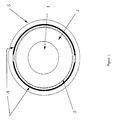
- One embodiment of the invention uses electrical resistance to heat the fiber as is shown in Figure 1.
- a high OH pure silica core 1 is overlaid with an F-doped silica cladding 2.
- Cladding 2 in turn is overlaid with a protective, highly electrically insulating polyimide layer 3 which can also withstand exposure to elevated temperatures.
- a resistive element 4 such as a very thin layer of gold, is deposited on polyimide layer 3.
- resistive element 4 can be deposited on the fiber in-line as the fiber draw proceeds. It should be noted that resistive element 4 can assume a variety of embodiments providing it possesses sufficient resistance to generate heat when it conducts electric current.
- an insulating sheath 5 overlays resistive element 4 to provide thermal and electrical insulation.
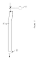
- FIG 2 shows an embodiment of Figure 1 with electrical current supply means 21.
- Electric current supply means 21 can be any traditional low voltage supply source such as a battery.
- resistive element 4 By conducting electricity through resistive element 4, resistive heat is generated.
- a compact, easy to handle silica lightguide 22 with improved UV transmission can be maintained at 200 C to 400 C via its electric resistance.
- the relatively small current that must be carried through the metallic resistance elements makes this a very elegant and cost effective way to achieve a warm operating fiber.
- diodes and other IR light sources can be used to heat the lightguide.
- a high OH content silica fiber not only offers higher performance in transmitting UV light, but also tends to absorb IR light.
- the fiber can be heated.
- an IR irradiation means 31 generates IR light which is directed down fiber 32.
- an IR reflector 33 is used at the fiber's end to reflect the IR light back through the fiber.
- Another embodiment of the IR irradiating means 31 may involve employing a source at each end of the fiber. It should be understood, however, that many modes of irradiating the fiber are possible. If the IR method of self-heating is used with high OH level cores, the fiber cross-sections would appear similar to Figure 1 although it would not have resistive element 4.
- the fiber can be further enhanced by the addition of a microporous silica layer.
- a microporous silica layer 41 can be overlaid on the cladding as shown in Figure 4A.
- a microporous silica layer 42 can be cured so that it will function as a cladding when directly overlaid on the fiber core 1 as shown in Figure 4B.
- the microporous silica layer as cladding.
- the main damage in standard types of fibers occurs in the vicinity of the core/clad boundary. It is thought that the tension at the boundary can function as an area of incipient faults which, when activated, may contribute to the degradation of the UV transmission.
- the stress at this boundary is significantly less for the sol-gel derived cladding in which both core and cladding are composed of the same purity of silica.
- the lower processing temperatures for the sol-gel method may also reduce the tension.
- the microporous silica layer cladding is expected to have improved resistance to UV degradation over standard core/clad fibers.
- the silica layer can be loaded with either hydrogen or deuterium gas before the polyimide layer is applied.
- the presence of the hydrogen or deuterium gas in the microporous layer provides a means for "chemically annealing" UV absorbing defects created during the fiber manufacturing process or during the transmission of UV light. As mentioned in the first paragraphs above, it has been found that the majority ofthe damage sites lie in the 8-10 ⁇ m region of the core/clad interface. This is a reasonable distance for the hydrogen or deuterium to diffuse to deactivate the defects.
- a hydrogen/deuterium loaded microporous silica layer 52 is coated in-line with a hermetic coating 53, such as metal or silicon nitride.
- a hermetic coating 53 such as metal or silicon nitride. This hermetic coating would reduce the escape over time of the hydrogen or deuterium gas through the microporous silica layer.
- the strength and resistance of the fiber to mechanical degradation in moist or wet environments is further improved by a hermetic coating.
- the steps employed to create the microporous layer can be modified by introducing nitrogen into the outer "skin" of the sol-gel layer. This skin is then converted into a continuous layer of silicon nitride. The remainder of the sol-gel layer is vitrified to the microporous silica state.
- a polyimide layer 54 is added over the hermetic coating 53. This layer serves to protect the fiber and to facilitate its handling during the manufacturing process.
- a polyimide layer 61 overlies the microporous silica layer 42.
- a metallic or other hermetic coating 62 is applied over the polyimide layer 61, and a second polyimide layer 63 is applied over the hermetic coating 62. This does create a slightly larger cross section for the fiber, however, handling the fiber during production is easier and safer.
Landscapes
- Physics & Mathematics (AREA)
- Health & Medical Sciences (AREA)
- Toxicology (AREA)
- General Physics & Mathematics (AREA)
- Optics & Photonics (AREA)
- Optical Fibers, Optical Fiber Cores, And Optical Fiber Bundles (AREA)
Description
- The present invention relates to optical fibers (lightguides) which are used in remote spectroscopy applications and in medical applications. These applications require the transmission of either ultra-violet (UV) laser energy for performing surgical procedures or lower energy, UV light for irradiating or illuminating a surface.
- A growing number of applications in spectroscopy and medicine are being designed to isolate the spectrometer or the medical laser/light source from the actual site being viewed or operated on. Optical fibers play a critical part in making such applications possible. In these applications, a need exists to have good, stable transmission in the wavelength region below 325 nm as well as throughout the visible near-IR (infra-red) region of the spectrum. Although spectroscopic applications employ low energy irradiation sources for extended periods of time and the medical applications -- especially surgical applications -- employ high energy sources for short durations, both applications need stable (i.e. low UV sensitive) optical fibers to function properly. Small drifts in the transmission properties over time affect the output in spectroscopic applications perhaps greater than absorbing defects affect laser light in surgical procedures.
- Generally speaking, optical fibers with pure silica cores are the most resilient to irradiation damage if they have a minimum of latent defect centers. Similar to an optical fiber's exposure to ionizing radiation (see, e.g., D.L. Griscom, Overview of Radiation Effects in Fiber Optics, 541 SPIE Proc. 70-88 (1985)), increased exposure to UV radiation increases a fiber's transmission loss (see, e.g. U. Grzesik et al., Reduction of Photodegradation in Optical Fibers for Excimer Laser Radiation, 1649 SPIE Proc. 80-90 (1992)). The transmission performance of the lightguides degrades particularly strongly and quickly when the fibers are used for the transmission of wavelengths below 280 nm (i.e. the far UV range). Similar problems are observed using pulsed excimer laser transmission at 308 nm. The degradation in transmission is observed with Silica/Silica fibers, which usually have a pure, high OH content silica core with a fluorine doped silica cladding, and with Plastic Clad Silica (PCS) optical fibers. The problem can be solved currently only by either frequently replacing the fibers or cutting off the end of the fiber which is exposed to the source of the UV radiation (i.e. the end receiving the highest UV exposure per unit time) and re-terminating the fiber.
- The defect centers, which cause the largest decreases in transmission in the UV region for major absorptions at 163 nm, 248 nm, and 210 nm, are identified as Si-Si, Si3 +, and E-centers respectively and are related to oxygen vacancies. The process of fiber drawing increases the vacancy defect population, and it has been found that the maximum concentration of the vacancies is in the 8-10 µm layer of the core near the cladding layer. The presence of high OH content in the core mitigates much of these problems, but sacrifices transmission in the regions above 820 nm where the overtones of the strong OH bond absorption occur. Fortunately, for most UV applications of remote spectroscopy or of surgery, moderate to high OH levels in the core pose no major detriment.
- Cardarelli et al. (US Patent No. 4,979,796) describes a thermally controlled optical fiber. In Cardarelli the problem solved is described as a temperature stability problem during use of an optical fiber gyroscope. In the art it is well known such fibers are low OH single mode optical fibers, which operate typically at wavelengths greater than 820 nm. The Cardarelli solution is to provide protection from ambient temperature variations by raising the temperature of the optical fiber above ambient and maintaining a very controlled temperature. This is the application, to an optical fiber, of the well known technique for making electronic devices tbermally insensitive by heating the device slightly above the highest expected ambient temperature. Typically temperatures of 35°C to 50°C are employed. In most such instances, to work properly the temperature must be controlled to within a small fraction of a degree Celsius. Furthermore, as noted in the previous references on radiation effects, most low OH fibers are adversely affected by high radiation doses.
- In contrast the present invention is for a lightguide for stable transmission of UV light by means of elevating the temperature of the lightguide to a range between 200°C and 400°C and maintaining the lightguide at this temperature during its operation. The fiber of the present invention has a high OH, pure silica core. Further, unlike in Cardarelli, the elevated temperature, described and employed in the present invention, may vary over a wide range while in operation. For some embodiments, as described below it is expected that a significant variance will occur either along the length of the optical fiber or across the fiber cross section.
- The present invention is thus directed at a lightguide, at a method of making the lightguide, and at a method of using the lightguide for stable transmission of UV light. The lightguide includes a high OH, pure silica core, a cladding overlying the core, and a resistive element overlying the cladding for elevating the temperature of the fiber. The resistive element has sufficient resistance to produce heat when conducting electric current. Alternatively instead of the overlying resistive element, the fiber can be heated by irradiating the high Oh, pure silica core with IR light at an OH absorption wavelength. Both these means for heating the lightguide can be enhanced if the cladding consists of a microporous silica layer or if the cladding is overlaid with a microporous silica layer. Moreover, the UV transmission properties of the fiber are further enhanced by impregnating the microporous silica layer with hydrogen or deuterium gas. A preferred embodiment of the invention also uses a hermetic coating over the microporous silica layer to retard the diffusion of the gas from the fiber.
- The features of the present invention, which are believed to be novel, are set forth with particularity in the appended claims. The invention may best be understood by reference to the following description taken in conjunction with the accompanying drawings, wherein like reference numbers identify like elements, and wherein:
- Figure 1 shows a cross section of the invention using resistive elements as the heating means;
- Figure 2 shows the embodiment of Figure 1 applied to the electric current means;
- Figure 3 shows the invention using IR light as the heating means;
- Figure 4A shows the invention with a microporous layer over the cladding;
- Figure 4B shows the invention with a microporous layer as the cladding;
- Figure 5 shows the invention with a hermetic coating directly over the gas impregnated microporous silica layer;
- Figure 6 shows the invention with a polyimide layer directly over the gas impregnated microporous silica layer.
-
- The present invention is directed at a fiber having improved properties for the transmission of UV laser energy or UV light. Recovery of the transmission properties of silica lightguides has been observed after the degraded fibers "age" at room temperatures for long periods of time. The present invention realizes, however, that the recovery process can be greatly improved by holding the irradiated fibers at an elevated temperature while in use. A temperature range of 200 °C to 400 °C is particularly effective, and a preferred temperature is around 300 °C. To this end, the invention uses two basic heating mechanisms and combinations thereof. These mechanisms for heating the fiber are electrical resistance and IR absorption. Moreover, each mechanism can be enhanced with the addition of a microporous layer enriched with hydrogen or deuterium gas.
- One embodiment of the invention uses electrical resistance to heat the fiber as is shown in Figure 1. here, a high OH
pure silica core 1 is overlaid with an F-doped silica cladding 2. Cladding 2 in turn is overlaid with a protective, highly electrically insulatingpolyimide layer 3 which can also withstand exposure to elevated temperatures. Using a commonly known metallizing technique such as sputtering, aresistive element 4, such as a very thin layer of gold, is deposited onpolyimide layer 3. Alternatively,resistive element 4 can be deposited on the fiber in-line as the fiber draw proceeds. It should be noted thatresistive element 4 can assume a variety of embodiments providing it possesses sufficient resistance to generate heat when it conducts electric current. Finally, aninsulating sheath 5 overlaysresistive element 4 to provide thermal and electrical insulation. - Figure 2 shows an embodiment of Figure 1 with electrical current supply means 21. Electric current supply means 21 can be any traditional low voltage supply source such as a battery. By conducting electricity through
resistive element 4, resistive heat is generated. In this way a compact, easy to handle silica lightguide 22 with improved UV transmission can be maintained at 200 C to 400 C via its electric resistance. The relatively small current that must be carried through the metallic resistance elements makes this a very elegant and cost effective way to achieve a warm operating fiber. - Preliminary calculations indicate that a 3 meter length of fiber with a 1 mm OD, suspended in air, would require about three watts to maintain it at 300 °C. Such energy levels should be available even in remote applications. Smaller diameter fibers would require proportionately less energy as would shorter lengths of fiber. Higher energy input would be needed, obviously, for longer lengths and if the ambient temperature around the fiber was significantly below normal indoor temperatures. Temperature monitoring and regulation along the fiber can be achieved by means of coaxially deployed miniature thermocouples or mid-IR optical fibers (silver halide based fibers capable of transmitting energy in the mid IR region, i.e. wavelengths between 4-20 µm).
- Alternatively, diodes and other IR light sources can be used to heat the lightguide. A high OH content silica fiber not only offers higher performance in transmitting UV light, but also tends to absorb IR light. By irradiating the fiber at wavelengths which OH absorbs, i.e. overtones of 2.9 µm, the fiber can be heated. As depicted in Figure 3, an IR irradiation means 31 generates IR light which is directed down
fiber 32. In this particular embodiment anIR reflector 33 is used at the fiber's end to reflect the IR light back through the fiber. Another embodiment of the IR irradiating means 31 may involve employing a source at each end of the fiber. It should be understood, however, that many modes of irradiating the fiber are possible. If the IR method of self-heating is used with high OH level cores, the fiber cross-sections would appear similar to Figure 1 although it would not haveresistive element 4. - Both the electrical resistance and IR absorption schemes for heating, the fiber can be further enhanced by the addition of a microporous silica layer. A
microporous silica layer 41 can be overlaid on the cladding as shown in Figure 4A. Alternatively, amicroporous silica layer 42 can be cured so that it will function as a cladding when directly overlaid on thefiber core 1 as shown in Figure 4B. - There is a particular advantage to using the microporous silica layer as cladding. As described earlier, the main damage in standard types of fibers occurs in the vicinity of the core/clad boundary. It is thought that the tension at the boundary can function as an area of incipient faults which, when activated, may contribute to the degradation of the UV transmission. The stress at this boundary is significantly less for the sol-gel derived cladding in which both core and cladding are composed of the same purity of silica. The lower processing temperatures for the sol-gel method may also reduce the tension. Thus, the microporous silica layer cladding is expected to have improved resistance to UV degradation over standard core/clad fibers.
- In a preferred embodiment, the silica layer can be loaded with either hydrogen or deuterium gas before the polyimide layer is applied. The presence of the hydrogen or deuterium gas in the microporous layer provides a means for "chemically annealing" UV absorbing defects created during the fiber manufacturing process or during the transmission of UV light. As mentioned in the first paragraphs above, it has been found that the majority ofthe damage sites lie in the 8-10 µm region of the core/clad interface. This is a reasonable distance for the hydrogen or deuterium to diffuse to deactivate the defects.
- In a preferred embodiment shown in Figure 5, a hydrogen/deuterium loaded microporous silica layer 52 is coated in-line with a
hermetic coating 53, such as metal or silicon nitride. This hermetic coating would reduce the escape over time of the hydrogen or deuterium gas through the microporous silica layer. In addition to containing the hydrogen/deuterium gas, the strength and resistance of the fiber to mechanical degradation in moist or wet environments is further improved by a hermetic coating. - To create the silicon nitride coating, the steps employed to create the microporous layer can be modified by introducing nitrogen into the outer "skin" of the sol-gel layer. This skin is then converted into a continuous layer of silicon nitride. The remainder of the sol-gel layer is vitrified to the microporous silica state.
- Over the
hermetic coating 53, apolyimide layer 54 is added. This layer serves to protect the fiber and to facilitate its handling during the manufacturing process. In an alternative embodiment of the enhanced invention shown in Figure 6, apolyimide layer 61 overlies themicroporous silica layer 42. A metallic or otherhermetic coating 62 is applied over thepolyimide layer 61, and asecond polyimide layer 63 is applied over thehermetic coating 62. This does create a slightly larger cross section for the fiber, however, handling the fiber during production is easier and safer. By permitting handling of the fiber after the microporous silica layer has been formed and stabilized, a better and more optimal loading of the fiber with the hydrogen/deuterium gas is possible and a cost effective application of the hermetic and protective coatings can be employed. - Obviously, numerous modifications and variations of the present invention are possible in the light of the above teachings. It is therefore understood that within the scope of the appended claims, the invention may be practiced otherwise than as specifically described herein.
Claims (9)
- A lightguide (22, 32) for stable transmission of UV light, said lightguide, having a high OH, pure silica core (1) and a cladding (2) overlaying said core, said cladding being a lower refractive index silica, and characterized in that it further comprises:a resistive element (4), overlying said cladding, having sufficient resistance to heat said lightguide in the range of 200°C to 400°C.
- A combination of a lightguide (22, 32) for stable transmission of UV light and heating means, characterized in that
said lightguide has a high OH pure silica core (1) and a cladding (2) overlaying
said core; and
said heating means is an IR irradiating means for irradiating said high OH pure silica core at an OH absorption wavelength and heating said lightguide in the range of 200°C to 400°C. - A lightguide for stable transmission of UV light according to claim 1 or a combination of a lightguide for stable transmission of UV light and heating means according to claim 2 further characterized by:said cladding (2) being a microporous silica layer (42); orsaid cladding (2) being a low refractive index doped silica which is overlaid with a microporous silica layer (41).
- The lightguide of claim 3 wherein the microporous silica layer (41 or 42) is further characterized by:containing a gas selected from the group consisting of hydrogen and deuterium; and preferentially having a hermetic coating (53) overlaying the gas-loaded microporous silica layer (52) to retard the diffusion of the gas from the layer (52).
- A process to manufacture a lightguide (22, 32) for stable transmission of UV light or UV laser energy, the process including drawing a silica core (1) having a high OH content, applying a cladding (2) to the core and providing a heating means (4) capable of heating said lightguide in the range of 200°C to 400°C and characterized by:applying, as cladding (2), a sol-gel coating; curing the sol-gel coating in-line to provide a microporous silica coating (42); and preferentially impregnating the microporous silica layer (42, now 52) with a gas selected from the group consisting of hydrogen and deuterium, before providing said heating means.
- A process according to Claim 5 which is further characterized by:either introducing nitrogen to the microporous silica layer's (52) outer surface and converting the outer surface to a hard impermeable silicon nitride (53); orapplying a hermetic coating (53) directly over the microporous silica layer (52) following the impregnation of gas; or applying a polyimide layer (61) directly on the microporous silica layer (52) following impregnation of gas and then applying a hermetic coating (62) over the polyimide layer and finally preferentially applying a second polyimide layer (63) over the hermetic coating (62).
- A method for stable transmission of UV light, comprising the steps of:providing an optical fiber, lightguide (22, 32), having a high OH, pure silica core (1) overlaid with a lower refractive index doped silica, or a micro porous silica cladding (2); and transmitting UV light in the lightguide, characterized by the further step of:providing heating means for elevating and maintaining the temperature of the lightguide to between 200 °C and 400 °C during said UV light transmission.
- The method for stable transmission of UV light according to claim 7 wherein said step of providing heating means comprises the applying of a resistive element (4) over said cladding (2) during production of said lightguide (22, 32) and applying a sufficient voltage to said resistive element to raise the temperature of lightguide to the indicated range.
- The method for stable transmission of UV light according to claim 7 wherein said step of providing heating means comprises the irradiating of said high OH, pure silica core at an OH absorption wavelength within the IR region with an IR irradiating means.
Applications Claiming Priority (2)
| Application Number | Priority Date | Filing Date | Title |
|---|---|---|---|
| US257550 | 1994-06-09 | ||
| US08/257,550 US5621843A (en) | 1994-06-09 | 1994-06-09 | Silica lightguide for UV applications |
Publications (2)
| Publication Number | Publication Date |
|---|---|
| EP0687924A1 EP0687924A1 (en) | 1995-12-20 |
| EP0687924B1 true EP0687924B1 (en) | 2002-05-02 |
Family
ID=22976744
Family Applications (1)
| Application Number | Title | Priority Date | Filing Date |
|---|---|---|---|
| EP95201514A Expired - Lifetime EP0687924B1 (en) | 1994-06-09 | 1995-06-08 | Improved silica lightguide for UV applications |
Country Status (3)
| Country | Link |
|---|---|
| US (1) | US5621843A (en) |
| EP (1) | EP0687924B1 (en) |
| DE (1) | DE69526538D1 (en) |
Families Citing this family (16)
| Publication number | Priority date | Publication date | Assignee | Title |
|---|---|---|---|---|
| US5901264A (en) * | 1997-06-12 | 1999-05-04 | Fiberguide Industries | Solar resistant optical fiber and method |
| DE19752713A1 (en) * | 1997-11-28 | 1999-06-02 | Zeiss Carl Fa | UV optical system with reduced aging |
| EP0972753B1 (en) * | 1998-07-15 | 2004-03-03 | Kitagawa Industries Co., Ltd. | Silica glass, optical element and optical fiber apparatus resistant to ultraviolet rays and radioactive rays, and manufacturing method therefor |
| KR20010086022A (en) * | 1998-11-12 | 2001-09-07 | 앤더슨 데릭 제이. | Tuning of optical devices |
| US6588236B2 (en) * | 1999-07-12 | 2003-07-08 | Kitagawa Industries Co., Ltd. | Method of processing a silica glass fiber by irradiating with UV light and annealing |
| AUPR230200A0 (en) * | 2000-12-22 | 2001-01-25 | Redfern Optical Components Pty Ltd | Tuning of optical devices |
| US6944380B1 (en) * | 2001-01-16 | 2005-09-13 | Japan Science And Technology Agency | Optical fiber for transmitting ultraviolet ray, optical fiber probe, and method of manufacturing the optical fiber probe |
| WO2002085072A1 (en) * | 2001-04-17 | 2002-10-24 | Koninklijke Philips Electronics N.V. | Insulating layer for a heating element |
| US7319803B2 (en) * | 2004-09-30 | 2008-01-15 | Totoku Electric Co., Ltd. | Heat-resistant optical fiber, a method of manufacturing the same, a method of fixing an optical fiber, and a heat-resistant optical fiber using a protective tube |
| US20060288740A1 (en) * | 2005-06-27 | 2006-12-28 | Totoku Electric Co., Ltd. | Heat-resistant optical fiber, a method of manufacturing the same, a method of fixing an optical fiber, and a heat-resistant optical fiber using a protective tube |
| EP2111564B1 (en) * | 2007-01-12 | 2018-04-25 | NKT Photonics A/S | Lifetime extending and performance improvements of micro-structured fibres via high temperature loading |
| EP2307915A2 (en) | 2008-07-11 | 2011-04-13 | NKT Photonics A/S | Lifetime extending and performance improvements of optical fibers via loading |
| US20130008180A1 (en) * | 2011-07-07 | 2013-01-10 | Diatzikis Evangelos V | Method and apparatus for distributed cleft and liberated tile detection achieving full coverage of the turbine combustion chamber |
| HK1243186A1 (en) | 2014-12-18 | 2018-07-06 | Nkt光子学有限公司 | A photonic crystal fiber, a method of production thereof and a supercontinuum light source |
| MX2018016029A (en) | 2016-06-29 | 2019-05-13 | Koninklijke Philips Nv | Light guides with low refractive coating to be used in water. |
| EP4345844A1 (en) * | 2022-09-29 | 2024-04-03 | Max-Planck-Gesellschaft zur Förderung der Wissenschaften e.V. | Image guiding device for image transfer from a reaction chamber and method for producing and regenerating the image guiding device |
Family Cites Families (10)
| Publication number | Priority date | Publication date | Assignee | Title |
|---|---|---|---|---|
| US3732425A (en) * | 1970-12-18 | 1973-05-08 | Gen Electric | Light conduit with double cladding |
| IT1130481B (en) * | 1980-06-16 | 1986-06-11 | Cselt Centro Studi Lab Telecom | PROCEDURE FOR THE REDUCTION OF THE CONTENT OF OXYDRY GROUPS IN PREFORMS FOR OPTICAL FIBERS MADE ACCORDING TO THE MCVD METHOD |
| US4773413A (en) * | 1983-06-13 | 1988-09-27 | Trimedyne Laser Systems, Inc. | Localized heat applying medical device |
| GB8429430D0 (en) * | 1984-11-21 | 1985-01-03 | Gen Electric Co Plc | Optical couplers |
| US4776665A (en) * | 1985-08-12 | 1988-10-11 | Siemens Aktiengesellschaft | Metal-free, self-bearing optical cable for high-tension overhead lines |
| US4893896A (en) * | 1987-07-10 | 1990-01-16 | Mitsubishi Cable Industries, Ltd. | Energy transmission optical fiber |
| US5242437A (en) * | 1988-06-10 | 1993-09-07 | Trimedyne Laser Systems, Inc. | Medical device applying localized high intensity light and heat, particularly for destruction of the endometrium |
| US4979796A (en) * | 1989-12-15 | 1990-12-25 | The Charles Stark Draper Laboratory, Inc. | Thermally controlled optical fiber |
| US5235659A (en) * | 1992-05-05 | 1993-08-10 | At&T Bell Laboratories | Method of making an article comprising an optical waveguide |
| US5495548A (en) * | 1993-02-17 | 1996-02-27 | Her Majesty The Queen In Right Of Canada, As Represented By The Minister Of Communications | Photosensitization of optical fiber and silica waveguides |
-
1994
- 1994-06-09 US US08/257,550 patent/US5621843A/en not_active Expired - Fee Related
-
1995
- 1995-06-08 DE DE69526538T patent/DE69526538D1/en not_active Expired - Lifetime
- 1995-06-08 EP EP95201514A patent/EP0687924B1/en not_active Expired - Lifetime
Non-Patent Citations (1)
| Title |
|---|
| 541 SPIE Proceedings (1985), pages 70-85 E.J. Friebele et al.: "Overview of radiation effects in fiber optics" * |
Also Published As
| Publication number | Publication date |
|---|---|
| DE69526538D1 (en) | 2002-06-06 |
| EP0687924A1 (en) | 1995-12-20 |
| US5621843A (en) | 1997-04-15 |
Similar Documents
| Publication | Publication Date | Title |
|---|---|---|
| US5621843A (en) | Silica lightguide for UV applications | |
| CN101838114B (en) | Method of treatment of optical fibers with deuterium | |
| US6130981A (en) | Gamma radiation sterilized fiber optic UV delivery systems | |
| JPH07277770A (en) | Deactivated glass optical waveguide against increased hydrogen induced loss | |
| WO2010003422A2 (en) | Lifetime extending and performance improvements of optical fibers via loading | |
| Oto et al. | Optical fiber for deep ultraviolet light | |
| Saito et al. | Optical and mechanical properties of infrared fibers | |
| US6490399B1 (en) | Glass for optical waveguides or the like | |
| US6856713B2 (en) | Optical component and method of making the same | |
| CA2541735C (en) | Conditioning optical fibers for improved ionizing radiation response | |
| TW201235719A (en) | Photodarkening resistant optical fibers and fiber lasers incorporating the same | |
| EP0972753B1 (en) | Silica glass, optical element and optical fiber apparatus resistant to ultraviolet rays and radioactive rays, and manufacturing method therefor | |
| Lu et al. | Optical fiber for UV-IR broadband spectroscopy | |
| Dianov et al. | Long-period fiber gratings and mode-field converters fabricated by thermodiffusion in phosphosilicate fibers | |
| JP3800743B2 (en) | Optical fiber with long period grating and method of manufacturing the same | |
| Klein et al. | UV fibers for applications below 200 nm | |
| Khalilov et al. | High-OH fibers with higher stability in the UV-region | |
| JP2004252400A (en) | Fiber optic device with enhanced resistance to external environmental condition and its method | |
| JP3995000B2 (en) | Optical fiber bundle and manufacturing method thereof | |
| Raithel et al. | Short-and long-term damage and annealing of improved UV-fibers using broadband UV light-source | |
| JPS60146202A (en) | optical fiber | |
| JPH01262509A (en) | How to maintain radiation resistance in optical fibers | |
| Toh et al. | Elevated Temperature Measurement using Silica-core Optical Fibre | |
| JPH0129221Y2 (en) | ||
| JPH0634830A (en) | Fiber for ultraviolet ray transmission |
Legal Events
| Date | Code | Title | Description |
|---|---|---|---|
| PUAI | Public reference made under article 153(3) epc to a published international application that has entered the european phase |
Free format text: ORIGINAL CODE: 0009012 |
|
| AK | Designated contracting states |
Kind code of ref document: A1 Designated state(s): DE GB |
|
| 17P | Request for examination filed |
Effective date: 19960620 |
|
| 17Q | First examination report despatched |
Effective date: 19960806 |
|
| GRAG | Despatch of communication of intention to grant |
Free format text: ORIGINAL CODE: EPIDOS AGRA |
|
| GRAG | Despatch of communication of intention to grant |
Free format text: ORIGINAL CODE: EPIDOS AGRA |
|
| GRAH | Despatch of communication of intention to grant a patent |
Free format text: ORIGINAL CODE: EPIDOS IGRA |
|
| REG | Reference to a national code |
Ref country code: GB Ref legal event code: IF02 |
|
| GRAH | Despatch of communication of intention to grant a patent |
Free format text: ORIGINAL CODE: EPIDOS IGRA |
|
| GRAA | (expected) grant |
Free format text: ORIGINAL CODE: 0009210 |
|
| AK | Designated contracting states |
Kind code of ref document: B1 Designated state(s): DE GB |
|
| REG | Reference to a national code |
Ref country code: GB Ref legal event code: FG4D |
|
| REF | Corresponds to: |
Ref document number: 69526538 Country of ref document: DE Date of ref document: 20020606 |
|
| PG25 | Lapsed in a contracting state [announced via postgrant information from national office to epo] |
Ref country code: DE Free format text: LAPSE BECAUSE OF FAILURE TO SUBMIT A TRANSLATION OF THE DESCRIPTION OR TO PAY THE FEE WITHIN THE PRESCRIBED TIME-LIMIT Effective date: 20020803 |
|
| PLBE | No opposition filed within time limit |
Free format text: ORIGINAL CODE: 0009261 |
|
| STAA | Information on the status of an ep patent application or granted ep patent |
Free format text: STATUS: NO OPPOSITION FILED WITHIN TIME LIMIT |
|
| 26N | No opposition filed |
Effective date: 20030204 |
|
| PGFP | Annual fee paid to national office [announced via postgrant information from national office to epo] |
Ref country code: GB Payment date: 20050531 Year of fee payment: 11 |
|
| PG25 | Lapsed in a contracting state [announced via postgrant information from national office to epo] |
Ref country code: GB Free format text: LAPSE BECAUSE OF NON-PAYMENT OF DUE FEES Effective date: 20060608 |
|
| GBPC | Gb: european patent ceased through non-payment of renewal fee |
Effective date: 20060608 |