EP0687239B1 - Dispensing of attachments - Google Patents
Dispensing of attachments Download PDFInfo
- Publication number
- EP0687239B1 EP0687239B1 EP94910717A EP94910717A EP0687239B1 EP 0687239 B1 EP0687239 B1 EP 0687239B1 EP 94910717 A EP94910717 A EP 94910717A EP 94910717 A EP94910717 A EP 94910717A EP 0687239 B1 EP0687239 B1 EP 0687239B1
- Authority
- EP
- European Patent Office
- Prior art keywords
- attachment
- hollow slotted
- needle
- slotted needle
- attachments
- Prior art date
- Legal status (The legal status is an assumption and is not a legal conclusion. Google has not performed a legal analysis and makes no representation as to the accuracy of the status listed.)
- Expired - Lifetime
Links
Images



Classifications
-
- B—PERFORMING OPERATIONS; TRANSPORTING
- B65—CONVEYING; PACKING; STORING; HANDLING THIN OR FILAMENTARY MATERIAL
- B65C—LABELLING OR TAGGING MACHINES, APPARATUS, OR PROCESSES
- B65C7/00—Affixing tags
-
- B—PERFORMING OPERATIONS; TRANSPORTING
- B65—CONVEYING; PACKING; STORING; HANDLING THIN OR FILAMENTARY MATERIAL
- B65C—LABELLING OR TAGGING MACHINES, APPARATUS, OR PROCESSES
- B65C7/00—Affixing tags
- B65C7/003—Affixing tags using paddle-shaped plastic pins
- B65C7/005—Portable tools
- B65C7/006—Portable tools electrically actuated
Definitions
- the present invention relates to the dispensing of attachments and more particularly to the dispensing of attachments from continuously connected ladder stock.
- the attachment has an H-shape, and the ladder stock is formed from two elongated and continuous plastic side members coupled together by a plurality of plastic cross links, the cross links preferably being equidistantly spaced.
- the stock may be produced from flexible plastics material including nylon, polypropylene and other similar materials by molding or by stamping. Either manually or with the aid of specifically designed devices, individual attachments may be dispensed from the ladder stock to couple buttons to fabric, mechandising tags to articles of commerce, or, in general, any two desired articles. In those instances where the dispensing device has dual needles, the attachments severed from the stock can be used like staples to secure objects and items.
- U.S. Patent No.4,877,172 a device for dispensing attachments of the type described above is disclosed.
- the device disclosed therein includes a reciprocatively mounted shuttle which fixedly carries a pair of hollow slotted needles and which moves between an attachment severing position and an attachment dispensing position.
- a feed belt which is driven by a pair of sprockets, is used to incrementally advance the ladder stock so that, at the end of each attachment dispensing cycle, a single attachment is fed into the needles at the attachment severing location.
- a slidably mounted knife blade severs the attachment from the remainder of the ladder stock, and the shuttle is moved to the attachment dispensing location where the needles are aligned with a pair of plungers.
- the plungers are then inserted into the needles to expel the attachment therefrom. Thereafter, the plungers retract and the shuttle moves back into the attachment severing location to accept another attachment.
- the shuttle, feed belt, knife blade and plungers are mounted to a head member. The head member is driven between between an attachment dispensing position and a withdrawn position by an electric motor driven assembly.
- the aforementioned device has performed reasonably well in the dispensing of attachments, it has certain shortcomings.
- One such shortcoming is that the device not infrequently causes an attachment to be severed asymmetrically (see, e.g., Figs. 1A and 1B wherein a properly severed attachment 10a and an asymmetrically severed attachment 10b are respectively shown), thereby impairing its utility and/or aesthetic value.
- the principal reason for this undesired asymmetry is that the feed belt, which is used to advance the attachment through a feed drive and into the pair of needles, is separated from the needles by a rather considerable distance of approximately 6 inches. Consequently, if the feed belt does not properly advance the ladder stock over this 6-inch spacing, one or more improperly severed attachments may be formed.
- the shuttle mechanism of the above-mentioned device presents another such shortcoming.
- the shuttle moves back and forth between an attachment severing position and an attachment dispensing position.
- mechanical stops are strategically placed to limit movement of the shuttle. The stops, however, do not always function with the timing and positional precision required to precisely place the shuttle at its desired location at the appropriate time.
- a device for dispensing attachments from a plurality of interconnected attachments which comprises a first hollow slotted needle having a tip, a rear end and a first longitudinal axis extending therebetween; a first feed channel through which said plurality of interconnected attachments are fed; a feed wheel for feeding an attachment through said first feed channel into said first hollow slotted needle through said rear end; a knife for severing an individual attachment from said interconnected plurality of attachments; and a first ejector rod reciprocably movable along said first longitudinal axis with respect to said needle for ejecting an attachment disposed within said first hollow slotted needle through said tip after said attachment has been severed from said plurality of interconnected attachments, said first ejector rod being fixed from natural movement relative to said first hollow slotted needle, characterized in that said first feed channel intersects said first longitudinal axis behind said rear end of said needle and is oriented at an acute angle relative to the rear direction of said longitudinal axis of said hollow slotted needle; and said
- the angle at which said feeding means feeds an attachment into said hollow slotted needle is preferably large enough so that an attachment can be fed into said hollow slotted needle using said feeding means and can be ejected therefrom using said ejecting means without requiring said hollow slotted needle to be moved laterally relative to said feeding means or said ejecting means. In this way, a shuttling mechanism for the needle (or conversely, for the feeding means and/or the ejecting means) may be eliminated.
- the feed wheel is preferable located off-axis of said hollow slotted needle.
- Said feed wheel preferably has a plurality of teeth which are configured to engage and, thereby, to drive the movement of a length of continuously connected ladder stock.
- a feed belt is not needed.
- said feed wheel is preferably disposed at a distance of approximately 1.125 inches from the rear end of the hollow slotted needle, the above-described problem resulting from a large spacing between the feed belt and the hollow slotted needle of the device of U.S. Pat. No. 4,877,172 is substantially eradicated.
- the present device may be provided with only a single hollow slotted needle and corresponding ejector rod, the present device is preferably provided with a pair of such needles and corresponding ejector rods. In this manner, one transverse bar of an attachment may be inserted into and expelled from one of the two needles while the other transverse bar of the attachment is being inserted into and expelled from the other of the two needles.
- the one or more hollow slotted needles of the present device are preferably movable along their respective longitudinal axes.
- the one or more hollow slotted needles, the feeding means, the ejecting means and the severing means are all preferably mounted on a head member which moves between an attachment dispensing position and a withdrawn position. Movement of the head member is preferably driven by an electric motor assembly which preferably includes a clutch means for coupling said electric motor to said head assembly in response to a user command.
- FIGs. 2 and 3 there are shown side and front views, respectively, of a device for dispensing attachments, the device being constructed according to the teachings of the present invention and represented generally by reference numeral 11.
- reference numeral 11 For simplicity and clarity, parts not directly pertaining to the invention are only diagrammatically shown in the drawings and are not described in detail below.
- device 11 is used to sever individual attachments from continuously connected ladder stock and to dispense and attach such individual attachments to desired workpieces.
- the following described device is intended for use with attachments of the type consisting of two plastic side members coupled by a plastic crosslink (such as shown in Fig. 1A).
- the device 11 includes duplicates of various components (e.g. needles 35-1 and 35-2).
- the invention also encompasses dispensing and attaching devices useful with other types of attachments wherein only a single set of such components is provided.
- device 11 includes a frame, the frame including a base 13, a neck 15, an arm 17 onto which a reactor plate 19 is mounted, and a housing 21.
- Head member 29 is slidably mounted for vertical movement on mount 31, and as will be seen below, the sliding vertical movement of head member 29 relative to mount 31 is used to actuate the feeding, severing and ejecting mechanisms of device 11.
- Motor assembly 27 Also disposed within housing 21 is an electric motor assembly 27. Many of the components of motor assembly 27 are seated within mount 31 and are, therefore, not shown in Fig. 2; nevertheless, as can be seen from the following description, motor assembly 27 is generally similar in construction and operation to the arrangement disclosed in U.S. Pat. No. 4,877,172.
- Motor assembly 27 includes an electric motor 32 which, through a clutch (not shown), drives the vertical movement of head member 23 relative to mount 31. Actuation of the clutch by a solenoid assembly (not shown) is triggered through a foot operated switch (not shown). A crankarm (not shown) mounted on the clutch engages a yoke assembly 33 mounted on head member 29 (see Fig. 5). Clutch actuation allows for one full revolution of the crankarm, which reciprocates head member 29 downward in the expulsion direction, and then in the withdrawal direction for a complete dispensing cycle.
- FIGs. 4 through 6 portions of head assembly 23 and mount assembly 25 are shown in greater detail to illustrate the actuation and operation of the feeding, severing and ejecting mechanisms of device 11.
- head assembly 23 includes a pair of parallel hollow slotted needles 35-1 and 35-2. Needles 35 are attached to the bottom of head member 29 through a needle block 37. Each needle 35 is shaped to include a tip 39, a rear end 41 and a longitudinal axis extending therebetween and is oriented vertically so that its longitudinal axis is parallel to the direction in which head member 29 moves.
- Head assembly 23 also includes a feeding mechanism for feeding ladder stock attachments through a pair of feed channels 43-1 and 43-2 and into needles 35.
- said feeding mechanism comprises a rotatably mounted feed wheel 45.
- Feed wheel 45 has special teeth 47 on its outer surface suitably configured to mate with and to drive ladder stock.
- feed channels 43-1 and 43-2 and feed wheel 45 are oriented relative to needles 35 so that, for reasons to be further discussed below, attachments may be inserted into needles 35 at appropriate angles relative to their respective longitudinal axes.
- feed wheel 45 is preferably located a short distance from needles 35, e.g. approximately 1.125 inches as opposed to approximately 6 inches in the commercial embodiment of the device disclosed in U.S. Pat. No. 4,877,172, to minimize the risk that ladder stock will be advanced improperly to needles 35 and will be cut asymmetrically.
- Ratchet 49 is coupled to feed wheel 45 by means of shaft 53.
- Shaft 53 is rotatably mounted on a pair of brackets 55-1 and 55-2 fixedly mounted on head member 29.
- Pawl 51 which has a first end 57 adapted to engage the teeth of ratchet 49, is pivotally connected at its opposite end to a lever 59 which, in turn, is fixedly mounted on head member 29.
- a spring 61 which is attached at one end to paw 51 and at the other end to bracket 55-1, biases pawl 51 towards ratchet 49.
- a post 63 is fixedly mounted on mount 31 to act as a stop for lever 59.
- ratchet and pawl arrangement works as follows to rotate feed wheel 45: With head member 29 still in the midst of withdrawing vertically upwardly, lever 59 comes into contact with and is stopped by post 63. The differential in deceleration between lever 59 and its pivotally connected paw 51 causes pawl 51 to briefly pivot upwardly. As it pivots, pawl 51 engages ratchet 49 and causes its rotation, thereby causing feed wheel 45 to rotate similarly. Pawl 51 then resumes its previous orientation and is adapted to engage the next tooth of ratchet 49.
- head assembly 23 additionally includes a knife 65 which is used to sever an attachment which has been loaded into needles 35 from the remainder of a length of ladder stock.
- Knife 65 is mounted on a knife block 67 which, in turn, is connected to a knife actuating arm 69.
- Arm 69 which is pivotally connected to head member 29, is desirably controlled by a cam 71 fixedly mounted on mount 31. Initial movement of head member 29 in the downward, i.e. expulsion, direction drives a roller 73 mounted on the end of arm 69 over cam 71.
- Cam 71 is disposed at an angle which causes arm 69 to pivot, thereby urging knife 65 to move in the severing direction.
- Arm 69 is desirably spring-loaded so that the blade is retracted immediately after severing. It will be appreciated that Fig. 5 merely represents one side of the head assembly; duplicates of arm 69 and cam 71 are not seen in Fig. 5.
- Head assembly 23 further includes a pair of ejector rods 73-1 and 73-2 for expelling an individual attachment disposed within needles 35 out through their respective tips 39.
- Ejector rods 73-1 and 73-2 which are disposed along the longitudinal axes of needles 35-1 and 35-2, respectively, are fixedly mounted on a rack 75 which, in turn, is slidably mounted for vertical movement on head member 29.
- Vertical movement of rack 75 is controlled by a stationary rack 77, which is fixedly mounted on mount 31, and a gear assembly 79.
- Gear assembly 79 comprises a first gear 81 engaged with stationary rack 77 and a second gear 83 of greater diameter engaged with rack 75.
- Gears 81 and 83 are fixed to each other and are rotatably mounted to move with head member 29.
- first gear 81 in interaction with stationary rack 77 turns second gear 83, thus driving rack 75 in the expulsion direction relative to head member 29 and causing ejector rods 73 to enter needles 35 through their respective rear ends 41.
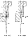
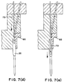
- Figs. 7(a) through 7(g) a series of schematic views are shown to illustrate the manner in which ladder stock attachments are fed, severed and ejected using device 11.
- Fig. 7(a) the lead attachment of a length of ladder stock is shown partially inserted into needle 35. As can be seen, the attachment has been fed into the needle at an angle so that its leading end is disposed along the longitudinal axis of the needle whereas its trailing end is bent off-axis. Knife 65 and ejector rod 73 are shown in their respective retracted positions.
- knife 65 is shown severing the partially inserted attachment from the remainder of the ladder stock. Once the attachment has been severed, its trailing end springs into alignment with needle 35. Ejector rod 65 is shown advancing towards needle 35.
- Fig. 7(c) knife 65 is shown returning to its retracted position, the severed attachment and ladder stock remaining in the position where they were at the time of severance. Ejector rod 73 is shown continuing to advance towards needle 35.
- ejector rod 73 is shown deflecting the leading end of the ladder stock as it travels towards needle 35.
- ejector rod 73 is shown pushing the attachment through needle 35.
- ejector rod 73 is shown returning to its retracted position, thereby allowing the leading end of the ladder stock to move back into position to be fed into needle 35.
- Fig. 7(g) the ladder stock is advanced so that the forwardmost attachment is partially inserted into needle 35 at an angle.
- the angle at which attachments are fed into needle 35 should be great enough so that ejector rod 73 can be inserted into needle 35 by deflecting the leading end of the remainder of the ladder stock, without requiring that needle 35 be moved laterally relative to ejector rod 73 and/or the ladder stock.
- the angle should be small enough to permit the ladder stock to be easily inserted into needle 35 through its rear end.
Landscapes
- Processing And Handling Of Plastics And Other Materials For Molding In General (AREA)
- Labeling Devices (AREA)
- Manufacturing Of Cigar And Cigarette Tobacco (AREA)
- Devices For Dispensing Beverages (AREA)
- Perforating, Stamping-Out Or Severing By Means Other Than Cutting (AREA)
- Sewing Machines And Sewing (AREA)
- Vehicle Interior And Exterior Ornaments, Soundproofing, And Insulation (AREA)
Abstract
Description
Claims (12)
- A device for dispensing attachments from a plurality of interconnected attachments comprising:characterized in thata) a first hollow slotted needle (35-1) having a tip (39-1), a rear end (41-1) and a first longitudinal axis extending therebetween;b) a first feed channel (43-1) through which said plurality of interconnected attachments are fed;c) a feed wheel (45) for feeding an attachment through said first feed channel (43-1) into said first hollow slotted needle (35-1) through said rear end (41-1);d) a knife (65) for severing an individual attachment from said inter-connected plurality of attachments; ande) a first ejector rod (73-1) reciprocably movable along said first longitudinal axis with respect to said needle for ejecting an attachment disposed within said first hollow slotted needle (35-1) through said tip (39-1) after said attachment has been severed from said plurality of interconnected attachments, said first ejector rod (73-1) being fixed from lateral movement relative to said first hollow slotted needle (35-1),1) said first feed channel (43-1) intersects said first longitudinal axis behind said rear end (41-1) of said needle and is oriented at an acute angle relative to the rear direction of said longitudinal axis of said hollow slotted needle (35-1); and2) said knife (65) is arranged to sever an individual attachment disposed within said first hollow slotted needle (35-1) after said attachment has been partially inserted into said first hollow slotted needle (35-1) while the following attachment remains at least partially within said first channel.
- The device as claimed in claim 1, characterized in that said first hollow slotted needle (35-1) is movable in the direction of said longitudinal axis.
- The device as claimed in claim 1, characterized in that said feed wheel (45) is disposed approximately 1.125 inches from said rear end (41-1) of said first hollow slotted needle (35-1).
- The device as claimed in claim 1, characterized in that said first hollow slotted needle (35-1), said feed wheel (45), said knife (65) and said first ejector rod (73-1) are mounted on a head member (29), said head member (29) being movable between an attachment dispensing position and a withdrawn position.
- The device as claimed in claim 4, characterized in that it further comprises a mount (31), said head member (29) being movably mounted between an attachment dispensing position and a withdrawn position on said mount (31).
- The device as claimed in claim 5, characterized in that it further comprises an electric motor driven assembly (27) for reciprocating said head member (29).
- The device as claimed in claim 1, characterized in that said feed wheel (45) is fixed laterally relative to said first hollow slotted needle (35-1).
- The device as claimed in claim 1, characterized in that said first ejector rod (73-1) is movable along said longitudinal axis of said first hollow slotted needle (35-1).
- The device as claimed in claim 1, characterized in that said feed wheel (45) has teeth (47) on its outer surface configured to mate with and to drive said plurality of interconnected attachments.
- The device as claimed in claim 1, characterized in that each of said plurality of interconnected attachments comprises a pair of side members coupled by a crosslink, said device further comprising a second hollow slotted needle (35-2) disposed along a second longitudinal axis parallel to said first longitudinal axis, a second feed channel (43-2) and a second ejector rod (732), said second feed channel (43-2) intersecting said second longitudinal axis behind the rear end of said second needle and being oriented at an acute angle relative to the rear direction of said second longitudinal axis of said second hollow slotted needle (35-2), wherein one of said side members of said plurality of interconnected attachments is fed by said feed wheel (45) through said first feed channel (43-1) and into said first hollow slotted needle (35-1) for dispensing therefrom by said first ejector rod (73-1) and the other of said side members of said plurality of interconnected attachments is fed by said feed wheel (45) through said second feed channel (43-2) and into said second hollow slotted needle (35-2) for dispensing therefrom by said second ejector rod (73-2) while the two side members of the following attachment remain at least partially within respectively said first and second feed channels.
- The device as claimed in claim 10, characterized in that said second hollow slotted needle (35-2) and said second ejector rod (73-2) are mounted on a head member (29).
- The device as claimed in claim 11, characterized in that it further comprises a pawl (51) and a ratchet (49) for driving said feed wheel (45).
Applications Claiming Priority (3)
| Application Number | Priority Date | Filing Date | Title |
|---|---|---|---|
| US2504493A | 1993-03-01 | 1993-03-01 | |
| US25044 | 1993-03-01 | ||
| PCT/US1994/001855 WO1994020372A1 (en) | 1993-03-01 | 1994-02-28 | Dispensing of attachments |
Publications (3)
| Publication Number | Publication Date |
|---|---|
| EP0687239A1 EP0687239A1 (en) | 1995-12-20 |
| EP0687239A4 EP0687239A4 (en) | 1996-10-16 |
| EP0687239B1 true EP0687239B1 (en) | 1999-01-20 |
Family
ID=21823742
Family Applications (1)
| Application Number | Title | Priority Date | Filing Date |
|---|---|---|---|
| EP94910717A Expired - Lifetime EP0687239B1 (en) | 1993-03-01 | 1994-02-28 | Dispensing of attachments |
Country Status (10)
| Country | Link |
|---|---|
| US (1) | US5433366A (en) |
| EP (1) | EP0687239B1 (en) |
| JP (1) | JP3514762B2 (en) |
| KR (1) | KR100307682B1 (en) |
| AU (1) | AU689467B2 (en) |
| CA (1) | CA2157287C (en) |
| DE (1) | DE69416114D1 (en) |
| MY (1) | MY112387A (en) |
| SG (1) | SG47973A1 (en) |
| WO (1) | WO1994020372A1 (en) |
Families Citing this family (15)
| Publication number | Priority date | Publication date | Assignee | Title |
|---|---|---|---|---|
| US5615816A (en) * | 1995-05-08 | 1997-04-01 | Avery Dennison Corporation | Dispensing of attachments |
| US5683025A (en) * | 1996-05-03 | 1997-11-04 | Avery Dennison Corporation | Apparatus for dispensing individual plastic fasteners from fastener stock |
| US5937951A (en) * | 1997-07-18 | 1999-08-17 | Ethicon Endo-Surgery, Inc. | Skin stapler with rack and pinion staple feed mechanism |
| US6244490B1 (en) | 1999-09-17 | 2001-06-12 | Avery Dennison Corporation | Reactor plate assembly |
| EP1311434B1 (en) | 2000-07-25 | 2006-02-08 | Avery Dennison Corporation | Plastic fasteners and needles for dispensing |
| US6536648B2 (en) | 2001-03-20 | 2003-03-25 | Avery Dennison Corporation | System for dispensing plastic fasteners |
| CN1299952C (en) * | 2001-05-29 | 2007-02-14 | 艾弗芮丹尼逊有限公司 | System for dispensing plastic fasteners |
| US6732899B2 (en) | 2002-04-04 | 2004-05-11 | Avery Dennison Corporation | System for dispensing plastic fasteners |
| US6561405B2 (en) | 2001-05-29 | 2003-05-13 | Avery Dennison Corporation | System for dispensing plastic fasteners |
| US6726078B2 (en) | 2001-07-03 | 2004-04-27 | Avery Dennison Corporation | System for dispensing plastic fasteners |
| US7036680B1 (en) | 2004-04-07 | 2006-05-02 | Avery Dennison Corporation | Device for dispensing plastic fasteners |
| US20080190956A1 (en) * | 2006-11-06 | 2008-08-14 | John Earley | Device for dispensing plastic fasteners |
| US8657172B2 (en) | 2006-11-06 | 2014-02-25 | Avery Dennison Corporation | Device for dispensing plastic fasteners |
| US8413866B2 (en) * | 2006-11-06 | 2013-04-09 | Avery Dennison Corporation | Device for dispensing plastic fasteners |
| USD621863S1 (en) | 2008-02-11 | 2010-08-17 | Avery Dennison Corporation | Device for dispensing plastic fasteners |
Family Cites Families (13)
| Publication number | Priority date | Publication date | Assignee | Title |
|---|---|---|---|---|
| US3734375A (en) * | 1971-05-27 | 1973-05-22 | Dennison Mfg Co | Fastener inserting machine |
| US4039078A (en) * | 1973-04-04 | 1977-08-02 | Dennison Manufacturing Company | Fastener attachment stock |
| US3815798A (en) * | 1973-05-21 | 1974-06-11 | B Lavitch | Button fastener |
| US4179063A (en) * | 1976-03-29 | 1979-12-18 | Dennison Manufacturing Company | Feed and severing apparatus |
| US4288017A (en) * | 1977-08-24 | 1981-09-08 | Dennison Manufacturing Company | Method and apparatus for dispensing fasteners |
| IT8069016A0 (en) * | 1980-12-31 | 1980-12-31 | Battagliotti S N C E C M F Ven | PROCEDURE FOR THE AUTOMATIC FEEDING OF A GUN FOR SENDING ELEMENTS SUITABLE TO REMAIN IN PLANT SYSTEM FOR THE AUTOMATIC FEEDING OF SUCH GUN AND FOR THE PRODUCTION OF SUCH ELEMENTS GUN FOR SENDING THE ABOVE MENTIONS AND THE ELEMENTS THEMSELVES |
| US4533076A (en) * | 1981-11-25 | 1985-08-06 | Dennison Manufacturing Company | Dispensing of attachments |
| US4448194A (en) * | 1982-02-03 | 1984-05-15 | Ethicon, Inc. | Full stroke compelling mechanism for surgical instrument with drum drive |
| US4682721A (en) * | 1983-11-18 | 1987-07-28 | Monarch Marking Systems, Inc. | Tag dispensing and attaching apparatus |
| US4706362A (en) * | 1984-09-25 | 1987-11-17 | Monarch Marking Systems, Inc. | Method of attaching tags |
| US4877172A (en) * | 1988-09-02 | 1989-10-31 | Dennison Manufacturing Company | Dispensing of attachments |
| US5020713A (en) * | 1989-05-04 | 1991-06-04 | Kunreuther Steven J | Assembly of attachments and device for attaching same |
| WO1991004195A2 (en) * | 1989-09-15 | 1991-04-04 | Dennison Manufacturing Company | Dispensing of attachment members |
-
1994
- 1994-02-28 DE DE69416114T patent/DE69416114D1/en not_active Expired - Lifetime
- 1994-02-28 CA CA002157287A patent/CA2157287C/en not_active Expired - Fee Related
- 1994-02-28 WO PCT/US1994/001855 patent/WO1994020372A1/en not_active Ceased
- 1994-02-28 KR KR1019950703691A patent/KR100307682B1/en not_active Expired - Lifetime
- 1994-02-28 AU AU62998/94A patent/AU689467B2/en not_active Ceased
- 1994-02-28 JP JP52002094A patent/JP3514762B2/en not_active Expired - Lifetime
- 1994-02-28 EP EP94910717A patent/EP0687239B1/en not_active Expired - Lifetime
- 1994-02-28 SG SG1996005788A patent/SG47973A1/en unknown
- 1994-03-01 MY MYPI94000483A patent/MY112387A/en unknown
- 1994-12-12 US US08/356,788 patent/US5433366A/en not_active Expired - Lifetime
Also Published As
| Publication number | Publication date |
|---|---|
| CA2157287C (en) | 2000-04-18 |
| JP3514762B2 (en) | 2004-03-31 |
| KR960700935A (en) | 1996-02-24 |
| DE69416114D1 (en) | 1999-03-04 |
| EP0687239A4 (en) | 1996-10-16 |
| JPH08507741A (en) | 1996-08-20 |
| AU6299894A (en) | 1994-09-26 |
| KR100307682B1 (en) | 2002-02-28 |
| US5433366A (en) | 1995-07-18 |
| WO1994020372A1 (en) | 1994-09-15 |
| AU689467B2 (en) | 1998-04-02 |
| CA2157287A1 (en) | 1994-09-15 |
| SG47973A1 (en) | 1998-04-17 |
| EP0687239A1 (en) | 1995-12-20 |
| MY112387A (en) | 2001-06-30 |
Similar Documents
| Publication | Publication Date | Title |
|---|---|---|
| CA2157287C (en) | Dispensing of flexible plastic fasteners from ladder shaped stock using a hollow needle | |
| US4288017A (en) | Method and apparatus for dispensing fasteners | |
| US4877172A (en) | Dispensing of attachments | |
| US4533076A (en) | Dispensing of attachments | |
| US4456161A (en) | Method and apparatus for dispensing fasteners | |
| US4456123A (en) | Method and apparatus for dispensing fasteners | |
| US5024365A (en) | Apparatus for dispensing fasteners | |
| US4712677A (en) | Method and apparatus for dispensing fasteners | |
| US5388749A (en) | Electric powered apparatus for dispensing individual plastic fasteners from fastener stock | |
| US4331276A (en) | Dispensing of attachment members | |
| US5320269A (en) | Apparatus for dispensing individual plastic fasteners from continuously connected ladder stock | |
| EP0888727A2 (en) | Double "T" bar attachments for double needle attachers | |
| CA1144322A (en) | Method and apparatus for dispensing fasteners | |
| US5033664A (en) | Dispensing of attachment members | |
| US4610385A (en) | Tag dispensing and attaching apparatus | |
| US4682721A (en) | Tag dispensing and attaching apparatus | |
| US4485954A (en) | Tag assembly feeding mechanism | |
| GB2164891A (en) | Attaching tags to merchandise using fasteners | |
| EP1416821B1 (en) | System for dispensing plastic fasteners | |
| US4998661A (en) | Needle assembly for fastener dispensing apparatus | |
| EP1254051B1 (en) | Reactor plate assembly | |
| WO1991004195A2 (en) | Dispensing of attachment members | |
| US4634036A (en) | Tag dispensing and attaching apparatus | |
| US6892920B2 (en) | Two-stage actuation system for tag attaching tool | |
| WO2002074624A2 (en) | System for dispensing plastic fasteners |
Legal Events
| Date | Code | Title | Description |
|---|---|---|---|
| PUAI | Public reference made under article 153(3) epc to a published international application that has entered the european phase |
Free format text: ORIGINAL CODE: 0009012 |
|
| 17P | Request for examination filed |
Effective date: 19950927 |
|
| AK | Designated contracting states |
Kind code of ref document: A1 Designated state(s): BE DE ES FR GB GR IT LU NL PT |
|
| A4 | Supplementary search report drawn up and despatched |
Effective date: 19960829 |
|
| AK | Designated contracting states |
Kind code of ref document: A4 Designated state(s): BE DE ES FR GB GR IT LU NL PT |
|
| 17Q | First examination report despatched |
Effective date: 19970617 |
|
| GRAG | Despatch of communication of intention to grant |
Free format text: ORIGINAL CODE: EPIDOS AGRA |
|
| GRAG | Despatch of communication of intention to grant |
Free format text: ORIGINAL CODE: EPIDOS AGRA |
|
| GRAH | Despatch of communication of intention to grant a patent |
Free format text: ORIGINAL CODE: EPIDOS IGRA |
|
| GRAH | Despatch of communication of intention to grant a patent |
Free format text: ORIGINAL CODE: EPIDOS IGRA |
|
| GRAA | (expected) grant |
Free format text: ORIGINAL CODE: 0009210 |
|
| AK | Designated contracting states |
Kind code of ref document: B1 Designated state(s): BE DE ES FR GB GR IT LU NL PT |
|
| PG25 | Lapsed in a contracting state [announced via postgrant information from national office to epo] |
Ref country code: NL Free format text: LAPSE BECAUSE OF FAILURE TO SUBMIT A TRANSLATION OF THE DESCRIPTION OR TO PAY THE FEE WITHIN THE PRESCRIBED TIME-LIMIT Effective date: 19990120 Ref country code: GR Free format text: LAPSE BECAUSE OF NON-PAYMENT OF DUE FEES Effective date: 19990120 Ref country code: FR Free format text: LAPSE BECAUSE OF FAILURE TO SUBMIT A TRANSLATION OF THE DESCRIPTION OR TO PAY THE FEE WITHIN THE PRESCRIBED TIME-LIMIT Effective date: 19990120 Ref country code: ES Free format text: THE PATENT HAS BEEN ANNULLED BY A DECISION OF A NATIONAL AUTHORITY Effective date: 19990120 Ref country code: BE Free format text: LAPSE BECAUSE OF FAILURE TO SUBMIT A TRANSLATION OF THE DESCRIPTION OR TO PAY THE FEE WITHIN THE PRESCRIBED TIME-LIMIT Effective date: 19990120 |
|
| PG25 | Lapsed in a contracting state [announced via postgrant information from national office to epo] |
Ref country code: LU Free format text: LAPSE BECAUSE OF NON-PAYMENT OF DUE FEES Effective date: 19990228 |
|
| REF | Corresponds to: |
Ref document number: 69416114 Country of ref document: DE Date of ref document: 19990304 |
|
| PGFP | Annual fee paid to national office [announced via postgrant information from national office to epo] |
Ref country code: FR Payment date: 19990317 Year of fee payment: 6 |
|
| PGFP | Annual fee paid to national office [announced via postgrant information from national office to epo] |
Ref country code: DE Payment date: 19990318 Year of fee payment: 6 |
|
| ITF | It: translation for a ep patent filed | ||
| PG25 | Lapsed in a contracting state [announced via postgrant information from national office to epo] |
Ref country code: PT Free format text: LAPSE BECAUSE OF FAILURE TO SUBMIT A TRANSLATION OF THE DESCRIPTION OR TO PAY THE FEE WITHIN THE PRESCRIBED TIME-LIMIT Effective date: 19990420 |
|
| PG25 | Lapsed in a contracting state [announced via postgrant information from national office to epo] |
Ref country code: DE Free format text: LAPSE BECAUSE OF FAILURE TO SUBMIT A TRANSLATION OF THE DESCRIPTION OR TO PAY THE FEE WITHIN THE PRESCRIBED TIME-LIMIT Effective date: 19990421 |
|
| EN | Fr: translation not filed | ||
| NLV1 | Nl: lapsed or annulled due to failure to fulfill the requirements of art. 29p and 29m of the patents act | ||
| PLBE | No opposition filed within time limit |
Free format text: ORIGINAL CODE: 0009261 |
|
| STAA | Information on the status of an ep patent application or granted ep patent |
Free format text: STATUS: NO OPPOSITION FILED WITHIN TIME LIMIT |
|
| 26N | No opposition filed | ||
| REG | Reference to a national code |
Ref country code: GB Ref legal event code: IF02 |
|
| PGFP | Annual fee paid to national office [announced via postgrant information from national office to epo] |
Ref country code: IT Payment date: 20120224 Year of fee payment: 19 Ref country code: GB Payment date: 20120224 Year of fee payment: 19 |
|
| GBPC | Gb: european patent ceased through non-payment of renewal fee |
Effective date: 20130228 |
|
| PG25 | Lapsed in a contracting state [announced via postgrant information from national office to epo] |
Ref country code: IT Free format text: LAPSE BECAUSE OF NON-PAYMENT OF DUE FEES Effective date: 20130228 |
|
| PG25 | Lapsed in a contracting state [announced via postgrant information from national office to epo] |
Ref country code: GB Free format text: LAPSE BECAUSE OF NON-PAYMENT OF DUE FEES Effective date: 20130228 |