EP0686835B1 - Compact thermocouple connector - Google Patents
Compact thermocouple connector Download PDFInfo
- Publication number
- EP0686835B1 EP0686835B1 EP95300014A EP95300014A EP0686835B1 EP 0686835 B1 EP0686835 B1 EP 0686835B1 EP 95300014 A EP95300014 A EP 95300014A EP 95300014 A EP95300014 A EP 95300014A EP 0686835 B1 EP0686835 B1 EP 0686835B1
- Authority
- EP
- European Patent Office
- Prior art keywords
- connector
- temperature
- thermocouple
- electrical contacts
- isothermal
- Prior art date
- Legal status (The legal status is an assumption and is not a legal conclusion. Google has not performed a legal analysis and makes no representation as to the accuracy of the status listed.)
- Expired - Lifetime
Links
- 230000008878 coupling Effects 0.000 claims description 11
- 238000010168 coupling process Methods 0.000 claims description 11
- 238000005859 coupling reaction Methods 0.000 claims description 11
- 239000000919 ceramic Substances 0.000 claims description 8
- 239000000758 substrate Substances 0.000 claims description 8
- 238000005259 measurement Methods 0.000 description 34
- 239000002184 metal Substances 0.000 description 12
- 229910052751 metal Inorganic materials 0.000 description 12
- 239000000523 sample Substances 0.000 description 11
- 238000009529 body temperature measurement Methods 0.000 description 9
- 150000002739 metals Chemical class 0.000 description 6
- RYGMFSIKBFXOCR-UHFFFAOYSA-N Copper Chemical compound [Cu] RYGMFSIKBFXOCR-UHFFFAOYSA-N 0.000 description 4
- 229910052802 copper Inorganic materials 0.000 description 4
- 239000010949 copper Substances 0.000 description 4
- 238000010586 diagram Methods 0.000 description 4
- 239000004020 conductor Substances 0.000 description 3
- 238000003780 insertion Methods 0.000 description 3
- 230000037431 insertion Effects 0.000 description 3
- 239000012080 ambient air Substances 0.000 description 2
- 239000011324 bead Substances 0.000 description 2
- 238000006243 chemical reaction Methods 0.000 description 2
- 230000006872 improvement Effects 0.000 description 2
- 238000002955 isolation Methods 0.000 description 2
- 239000000463 material Substances 0.000 description 2
- 239000004065 semiconductor Substances 0.000 description 2
- 238000000926 separation method Methods 0.000 description 2
- 229910052714 tellurium Inorganic materials 0.000 description 2
- PORWMNRCUJJQNO-UHFFFAOYSA-N tellurium atom Chemical compound [Te] PORWMNRCUJJQNO-UHFFFAOYSA-N 0.000 description 2
- 241000935974 Paralichthys dentatus Species 0.000 description 1
- 239000003570 air Substances 0.000 description 1
- 239000000956 alloy Substances 0.000 description 1
- 229910045601 alloy Inorganic materials 0.000 description 1
- 230000003466 anti-cipated effect Effects 0.000 description 1
- 238000013459 approach Methods 0.000 description 1
- 230000000295 complement effect Effects 0.000 description 1
- 238000005260 corrosion Methods 0.000 description 1
- 230000007797 corrosion Effects 0.000 description 1
- 238000011161 development Methods 0.000 description 1
- 230000000694 effects Effects 0.000 description 1
- 238000005516 engineering process Methods 0.000 description 1
- 238000007654 immersion Methods 0.000 description 1
- 238000009434 installation Methods 0.000 description 1
- 238000000034 method Methods 0.000 description 1
- 239000000203 mixture Substances 0.000 description 1
- 239000000615 nonconductor Substances 0.000 description 1
- 230000009467 reduction Effects 0.000 description 1
- 230000004044 response Effects 0.000 description 1
- 238000004088 simulation Methods 0.000 description 1
- 230000003068 static effect Effects 0.000 description 1
- 239000002470 thermal conductor Substances 0.000 description 1
Images


Classifications
-
- G—PHYSICS
- G01—MEASURING; TESTING
- G01K—MEASURING TEMPERATURE; MEASURING QUANTITY OF HEAT; THERMALLY-SENSITIVE ELEMENTS NOT OTHERWISE PROVIDED FOR
- G01K7/00—Measuring temperature based on the use of electric or magnetic elements directly sensitive to heat ; Power supply therefor, e.g. using thermoelectric elements
- G01K7/02—Measuring temperature based on the use of electric or magnetic elements directly sensitive to heat ; Power supply therefor, e.g. using thermoelectric elements using thermoelectric elements, e.g. thermocouples
- G01K7/10—Arrangements for compensating for auxiliary variables, e.g. length of lead
- G01K7/12—Arrangements with respect to the cold junction, e.g. preventing influence of temperature of surrounding air
-
- H—ELECTRICITY
- H05—ELECTRIC TECHNIQUES NOT OTHERWISE PROVIDED FOR
- H05K—PRINTED CIRCUITS; CASINGS OR CONSTRUCTIONAL DETAILS OF ELECTRIC APPARATUS; MANUFACTURE OF ASSEMBLAGES OF ELECTRICAL COMPONENTS
- H05K1/00—Printed circuits
- H05K1/02—Details
- H05K1/0201—Thermal arrangements, e.g. for cooling, heating or preventing overheating
-
- H—ELECTRICITY
- H05—ELECTRIC TECHNIQUES NOT OTHERWISE PROVIDED FOR
- H05K—PRINTED CIRCUITS; CASINGS OR CONSTRUCTIONAL DETAILS OF ELECTRIC APPARATUS; MANUFACTURE OF ASSEMBLAGES OF ELECTRICAL COMPONENTS
- H05K1/00—Printed circuits
- H05K1/02—Details
- H05K1/0296—Conductive pattern lay-out details not covered by sub groups H05K1/02 - H05K1/0295
- H05K1/0298—Multilayer circuits
-
- H—ELECTRICITY
- H05—ELECTRIC TECHNIQUES NOT OTHERWISE PROVIDED FOR
- H05K—PRINTED CIRCUITS; CASINGS OR CONSTRUCTIONAL DETAILS OF ELECTRIC APPARATUS; MANUFACTURE OF ASSEMBLAGES OF ELECTRICAL COMPONENTS
- H05K1/00—Printed circuits
- H05K1/18—Printed circuits structurally associated with non-printed electric components
-
- Y—GENERAL TAGGING OF NEW TECHNOLOGICAL DEVELOPMENTS; GENERAL TAGGING OF CROSS-SECTIONAL TECHNOLOGIES SPANNING OVER SEVERAL SECTIONS OF THE IPC; TECHNICAL SUBJECTS COVERED BY FORMER USPC CROSS-REFERENCE ART COLLECTIONS [XRACs] AND DIGESTS
- Y10—TECHNICAL SUBJECTS COVERED BY FORMER USPC
- Y10S—TECHNICAL SUBJECTS COVERED BY FORMER USPC CROSS-REFERENCE ART COLLECTIONS [XRACs] AND DIGESTS
- Y10S439/00—Electrical connectors
- Y10S439/913—Condition determining device, e.g. oxygen sensor, accelerometer, ionizer chamber, thermocouple
Definitions
- This invention relates generally to devices for electrical connectors and, particularly, to isothermal connectors for thermocouple temperature measurement and calibration systems.
- thermocouples have been used for many years to make accurate temperature measurements.
- a thermocouple consists of a junction of two dissimilar metals with wire leads connected to each half of the junction.
- the thermocouple generates a thermoelectric voltage that is a function of the junction temperature and the choice of the particular metals which form the junction. Because the thermoelectric voltage generated as a function of temperature can be determined for particular thermocouple junction, a voltage-measuring instrument can be used to measure the junction voltage and convert the voltage measurement into corresponding temperature information through a simple voltage to temperature conversion algorithm.
- a variety of different metals for use in the thermocouple junction have been employed to create different types of thermocouples to suit the requirements of different measurement tasks.
- thermocouple types include the anticipated temperature range of the measurement application and the required measurement accuracy.
- "J-type” and “K-type” thermocouples are examples of commonly available thermocouples which have well known characteristics in the industry for temperature range and accuracy.
- Temperature measurement instruments that utilize thermocouple probes will commonly accept J-type and K-type thermocouples and provide proper conversion of the measured junction voltage into a temperature reading according to IEC 584 and NIST (National Institute of Standards and Technology) temperature/voltage tables.
- thermocouple may be connected directly to a measuring instrument, making the task of measuring the thermocouple junction voltage straightforward. More commonly, however, the thermocouple is connected indirectly to the measuring instrument via thermocouple extension wires and a thermocouple connector which plugs into a corresponding connector on the measuring instrument in order to accommodate the rapid connection of different thermocouple probes to the measuring instrument.
- thermocouple extension wires and a thermocouple connector which plugs into a corresponding connector on the measuring instrument in order to accommodate the rapid connection of different thermocouple probes to the measuring instrument.
- thermocouple connector A blade-type thermocouple connector with metal contacts of a specified type and dimension has been standardized in the industry.
- Thermocouple connectors have an undesirable side effect.
- the metal-to-metal contact between the connector of the thermocouple and corresponding contact in the instrument connector forms another junction of dissimilar metals which contributes its own thermoelectric voltage to the measurement, thus making it necessary to take further steps to counteract the error voltage contributed to the measurement.
- One strategy is to measure the temperature of the connector junction in order to estimate and remove its thermoelectric voltage contribution from the measurement.
- the temperature of the connector junction may be measured by a temperature sensor that is typically, but not necessarily, located near the connector. To ensure accurate temperature readings by the instrument, it is important to minimize any temperature differences between the two contacts of the connector which form two separate junctions, one for each wire that is connected to the thermocouple. Furthermore, it is important to minimize the temperature difference between the temperature sensor and the connector-to-connector junctions. A temperature difference between the two contacts of the connector, or between the temperature sensor and the contacts, results in measurement errors which degrade the overall accuracy of the temperature measurement and cause the temperature measuring instrument to make erroneous temperature readings. Therefore, it is desirable that a thermocouple connector be "isothermal" in that the temperature between the two contacts and between the contacts and the temperature sensor is maintained at substantially the same temperature.
- U.S. Pat. No. 5,090,918 "Isothermal Termination Block Having A Multi-Layer Thermal Conductor" to Zoellick et. al, and assigned to Fluke Corporation, discloses an isothermal termination block that facilitates the connection of a plurality of thermocouple wire leads to a set of associated wire terminals.
- the isothermal termination block achieves improved thermal coupling between each pair of terminals and also between the terminals and a local temperature sensor mounted on the terminal block through the use of a multi-layer printed circuit board with embedded layers of thermal conducting material, allowing improved thermal conductivity in a substantially smaller physical size compared to prior art, among other advantages.
- thermocouple connectors While solving the problem of maintaining an isothermal relationship between the wire terminals and the local temperature sensor in a semi-permanent installation, does not address a concern regarding the settling time required for a stable measurement after the connection and re-connection of different thermocouple connectors.
- instrument connectors are typically smaller in size than terminal blocks. Zoellick et al. does not address the problem of maintaining temperature stability in a small physical size.
- the particular problem of small physical size in instrument thermocouple connectors is illustrated in the common situation where a thermocouple connector of one temperature is inserted into an instrument connector of another temperature.
- Thermal mass is a measure of the amount of thermal energy an object is capable of storing.
- Settling time is the minimum amount of time required for the temperatures of the two metal-to-metal junctions that form between the two connectors to stabilize and equalize to a degree that is sufficient for the desired measurement accuracy.
- thermocouple connector is polarized by making one pin larger than the other in order to prevent insertion of the thermocouple connector in reverse polarity into the instrument connector. Because the two pins are different sizes, the volume of metal between the pins necessarily differs and therefore the thermal mass of the pins differs, resulting in degraded measurement accuracy and longer settling times because the two junctions approach an equilibrium temperature at different rates.
- Prior art thermocouple connectors were not designed for isothermal operation nor optimized for settling time after connection.
- thermal mass of the electrical contact allows the contact to more rapidly equalize its temperature with that of another contact of a different temperature of a lesser thermal mass when the two contacts are thermally coupled with each other.
- Increased thermal mass of the contact also allows greater stability in the face of short-term variations in the ambient air temperature. Thus, it would therefore be desirable to provide a compact isothermal instrument connector with increased thermal mass that offers a reduced amount of settling time, increased measurement accuracy, and reduced susceptibility to changes in ambient temperature.
- an isothermal connector for thermocouple measurement systems that permits the insertion of a blade-type thermocouple connector with a substantial reduction in settling time and improvement in overall temperature stability in a measurement system.
- a pair of electrical contacts of an isothermal connector are electrically and thermally coupled to a corresponding pair of contacts of a blade-type thermocouple connector as it is inserted and held against the pair of contacts by a pair of spring clips.
- the isothermal nature of the isothermal connector is achieved through the use of the multi-layer circuit board containing embedded thermal conducting layers disclosed by Zoellick et al. as the thermally conductive member.
- the electrical contacts are rigidly mounted to the multi-layer circuit board to obtain both electrical and thermal contact with the multi-layer circuit board.
- a temperature sensor in the form of a thermistor, is also thermally coupled to the multi-layer circuit board to provide sensing of the temperature of the electrical contacts.
- the improved settling time is achieved by making the electrical contacts of a size and composition as to have a thermal mass substantially greater than the thermal mass of the corresponding set of contacts of the thermocouple to provide for improved settling time by proportionately reducing the contribution of the difference in thermal mass between the two pins. Furthermore, the substantial amount of thermal coupling between the contacts combined with their high thermal mass allows for higher measurement accuracy while maintaining an isothermal connector physically small in size because the metal-to-metal junctions are more thermally stable over changes in ambient temperature.
- An alternative embodiment of the present invention provides for a pair of contacts thermally and electrically coupled to a ceramic substrate which provides thermal coupling between the contacts to maintain an isothermal condition. Furthermore, the ceramic substrate forms a substantial part of the thermal mass required for a desired settling time.
- thermocouple temperature probe 10 comprised of a thermocouple 12, connecting leads 14, and a thermocouple connector 16.
- thermocouple connector 16 which is standardized in the industry as a blade-type connector allowing ease of connection.
- Thermocouple connector 16 is polarized, meaning it is designed to be inserted in only one direction in a corresponding connector by making the relative physical dimensions of a pair of corresponding contacts 18 substantially unequal, to maintain a desired polarity of the thermoelectric voltage generated by the thermocouple 12 to subsequent connections.
- Isothermal connector 24 consists of a thermally conductive member 30 in the form of a multi-layer printed circuit board, a pair of electrical contacts 26 which are thermally coupled to the thermally conductive member 30, and a temperature sensor 28 also thermally coupled to the thermally conductive member 30.
- the multi-layer printed circuit board provides a high degree of thermal conductivity through embedded layers of thermally conductive material to facilitate an isothermal condition between the electrical contacts 26 and the temperature sensor 28, meaning the temperature differences between each of the electrical contacts 26 and also between the electrical contacts 26 and the temperature sensor 28 are maintained at substantially the same temperature.
- the multi-layer printed circuit board functions as an electrical insulator between each of the electrical contacts 26 and the temperature sensor 28.
- Each of the electrical contacts 26 is electrically coupled to an input of the measurement circuit 22 via wires 32.
- the wires 32 may consist of embedded electrical traces within the multi-layer printed circuit board, insulated wires, or some combination thereof involving like metals whose junctions do not induce thermal voltages.
- the signal from the temperature sensor 28 is also coupled via the wires 32 to an input of a measurement circuit 22.
- the temperature sensor 28 can be any type of temperature sensitive element, such as a thermistor, a diode, or a transistor whose base-emitter junction voltage is proportional to the transistor ambient temperature.
- the measurement circuit 22 receives the thermoelectric voltage generated by the thermocouple 12 via the thermocouple connector 16 and isothermal connector 24
- Thermocouple connector 16 functions as the corresponding connector to isothermal. connector 24 in that the two connectors mate in the desired fashion with the proper connectors made between the corresponding contacts of each connector.
- the metal-to-metal contact between the electrical contacts 26 and each of the corresponding contacts 18 form two junctions which create two additional sources of thermoelectric voltage that contribute to the thermoelectric voltage sensed by the measurement circuit 22. Minimizing the error contributed by the connector junction voltages involves two strategies. First, the connector junctions must be maintained at the same temperature, that is, in an isothermal manner, to minimize the differential contribution of the two connector junction voltages to the desired thermoelectric voltage of the thermocouple 12.
- the measurement circuit by measuring the output signal of the temperature sensor 28 can account for the connector junction voltages.
- the temperature sensed by the temperature sensor 28 must substantially reflect the actual temperature of the electrical contacts 26 in order to accurately account for the error contribution of each contact to the desired thermoelectric voltage of the thermocouple 12.
- the second strategy to reduce the error induced by connector junction voltages involves the improvement of the dynamic performance capability of the isothermal connector which is constrained to a relatively small amount of physical space.
- the electrical contacts 26 of the isothermal connector 24 are chosen in such a manner that their thermal mass relative to the thermal mass of the corresponding contacts 18 is sufficient to permit a desired settling time.
- Settling time is the amount of time required for temperature differences between each of the electrical contacts 26 and the corresponding contacts 18 to equalize and reach a steady temperature value after the connector 16 is inserted into isothermal connector 24.
- the amount of thermal mass in each of the electrical contacts 26 was arrived at empirically by varying the volume of Tellurium copper material that forms the contact.
- a thermal mass ratio of five to one was empirically arrived at in development of a proposed commercial embodiment in order to allow an acceptably short settling time after insertion of the connector 16 into the isothermal connector 24.
- Tellurium copper an alloy well known in the art, was chosen as the contact material because of its superior ability to resist corrosion while providing adequate thermal mass per unit volume to maintain the compact size of the isothermal connector 24.
- Measurement circuit 36 which is coupled to the thermocouple connector 16 via the wires 14.
- Measurement circuit 36 represents an application in which temperature measurement instruments can be calibrated. By substituting a thermocouple 12 with a known temperature-compensated signal, the measurement circuit 36 is then adjusted to provide the desired response to the known signal and thereby calibrated. Calibration of a measurement circuit 36 requires a simulation of the signals provided by thermocouples to an accuracy that exceeds that of the measurement circuit 36, making the contributed error of the thermoelectric voltage from any connector junctions in the circuit more critical to control and account for.
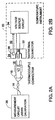
- FIG. 2B is a simplified block diagram of the temperature instrument 20 now comprising the isothermal connector 24 and a voltage source circuit 34 which performs a complementary function to that of the measurement circuit 22 of FIG. 1B by accurately simulating a thermoelectric junction voltage of a particular thermocouple type set to a predetermined temperature.
- the simulated voltage is coupled from an output of the voltage source circuit 34 to the electrical contacts 26.
- the temperature sensor 28 senses the temperature of the electrical contacts 26 and the signal from temperature sensor 28 is coupled via the wires 32 to an input of the voltage source circuit 34which reads the signal and generates a responsive amount of compensation voltage to the simulated voltage provided to the electrical contacts 26 to correct for contributed errors from the connector junction voltages developed between the contacts 18 and 26.
- the voltage source circuit 36 or measurement circuit 22 are selectably connected to the isothermal connector 24 in the temperature instrument 20, allowing the temperature instrument 20 to fulfill its intended role in maintaining thermocouple temperature measurement systems by allowing a user to verify the operation of the thermocouple 20 and to calibrate the measurement circuit 36.
- the requirements of the isothermal connector are identical for either measuring a thermocouple or in simulating a thermocouple because the thermoelectric voltages of the connector junctions contribute to measurement error regardless of the signal direction.
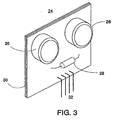
- FIG. 3 illustrates the preferred embodiment of the present invention.
- Isothermal connector 24 is comprised of the electrical contacts 26, temperature sensor 28, thermally conductive member 30 and the wires 32.
- the electrical contacts 26 are thermally coupled to the thermally conductive member 30 which is in the form of a multi-layer printed circuit board and further electrically coupled to the measurement circuit 22 or to the voltage source circuit 34 via the wires 32.
- Thermally conductive member 30 provides a substantial amount of thermal coupling between each of electrical contacts 26 and between the electrical contacts 26 and the temperature sensor 28 to provide an isothermal condition. To achieve further isolation from other sources of thermal energy, thermally conductive member 30 is maintained physically small to facilitate separation from thermal contact with disruptive thermal sources within the temperature instrument 20.
- the thermal mass necessary to achieve the desired settling time and temperature stability resides in the electrical contacts 26.
- the temperature sensor 28 is comprised of a thermistor which is thermally coupled to the electrical contacts 26 via the thermally conductive member 30. Temperature sensor 28 may be comprised of a thermistor or a semiconductor junction formed by a transistor or a diode.
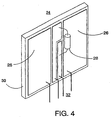
- FIG. 4 illustrates an alternative embodiment of the present invention.
- Isothermal connector 24 is comprised of the electrical contacts 26, temperature sensor 28, thermally conductive member 30, and wires 32.
- the electrical contacts 26 and the temperature sensor 28 are thermally coupled to the thermally conductive member 30 which is in the form of a ceramic substrate.
- the electrical contacts 26 consist of a layer of copper deposited on the surface of the ceramic substrate.
- the electrical contacts 26 are electrically coupled to the measurement circuit 22 or to the voltage source circuit 34 via the wires 32.
- Thermally conductive member 30 provides a substantial amount of thermal coupling between each of electrical contacts 26 and between electrical contacts 26 and the temperature sensor 28 to provide an isothermal condition.
- Temperature sensor 28 may be comprised of a thermistor or a semiconductor junction formed by a transistor or a diode.
- thermally conductive member 30 is maintained physically small to facilitate separation from thermal contact with disruptive thermal sources within the temperature instrument 20.
- the physical dimensions of the alternative embodiment of the isothermal connector 24 are substantially the same as those of the preferred embodiment.
- the thermal mass necessary to achieve the desired settling time and temperature stability resides in both the electrical contacts 26 and in the thermally conductive member 30.
- the ceramic substrate has a relatively high thermal mass, allowing the dimensions of the ceramic substrate as well as the volume of copper forming the electrical contacts 26 to be selected to determine the thermal mass of the isothermal connector 24.
- FIG. 5 there is shown a simplified cut-away illustration of the isothermal connector 24 as installed in the temperature instrument 20.
- a pair of spring clips 38 provides physical clamping pressure on the corresponding contacts 18 of the thermocouple connector 16, holding the electrical contacts 26 against the corresponding contacts 18 for both electrical and thermal coupling.
- the isothermal connector 24 is physically separated from the rest of the temperature instrument 20 and housed within a physical cavity to minimize disruption from other sources of thermal energy within the instrument 20 or from short term changes in ambient air temperature outside the temperature instrument 20.
- the electrical contacts 26 may be made of any electrically conductive material and the amount of thermal mass may be varied to obtain desired accuracy and settling times of measurement systems in which thermoelectric junction voltages are of concern. It is however desirable that the thermal mass of the isothermal connector 24 be at least twice, and preferably at least 5 times, that of the thermocouple connector 16. The shape and number of the electrical contacts 26 may be altered to accommodate different connector types which may be either male or female. Therefore, the present invention should be determined by the following claims.
Landscapes
- Physics & Mathematics (AREA)
- General Physics & Mathematics (AREA)
- Measuring Temperature Or Quantity Of Heat (AREA)
Description
- This invention relates generally to devices for electrical connectors and, particularly, to isothermal connectors for thermocouple temperature measurement and calibration systems.
- Thermocouples have been used for many years to make accurate temperature measurements. A thermocouple consists of a junction of two dissimilar metals with wire leads connected to each half of the junction. The thermocouple generates a thermoelectric voltage that is a function of the junction temperature and the choice of the particular metals which form the junction. Because the thermoelectric voltage generated as a function of temperature can be determined for particular thermocouple junction, a voltage-measuring instrument can be used to measure the junction voltage and convert the voltage measurement into corresponding temperature information through a simple voltage to temperature conversion algorithm. A variety of different metals for use in the thermocouple junction have been employed to create different types of thermocouples to suit the requirements of different measurement tasks. Typical selection parameters for thermocouple types include the anticipated temperature range of the measurement application and the required measurement accuracy. "J-type" and "K-type" thermocouples are examples of commonly available thermocouples which have well known characteristics in the industry for temperature range and accuracy. Temperature measurement instruments that utilize thermocouple probes will commonly accept J-type and K-type thermocouples and provide proper conversion of the measured junction voltage into a temperature reading according to IEC 584 and NIST (National Institute of Standards and Technology) temperature/voltage tables.
- The thermocouple may be connected directly to a measuring instrument, making the task of measuring the thermocouple junction voltage straightforward. More commonly, however, the thermocouple is connected indirectly to the measuring instrument via thermocouple extension wires and a thermocouple connector which plugs into a corresponding connector on the measuring instrument in order to accommodate the rapid connection of different thermocouple probes to the measuring instrument. A blade-type thermocouple connector with metal contacts of a specified type and dimension has been standardized in the industry.
- Thermocouple connectors have an undesirable side effect. The metal-to-metal contact between the connector of the thermocouple and corresponding contact in the instrument connector forms another junction of dissimilar metals which contributes its own thermoelectric voltage to the measurement, thus making it necessary to take further steps to counteract the error voltage contributed to the measurement. One strategy is to measure the temperature of the connector junction in order to estimate and remove its thermoelectric voltage contribution from the measurement.
- The temperature of the connector junction may be measured by a temperature sensor that is typically, but not necessarily, located near the connector. To ensure accurate temperature readings by the instrument, it is important to minimize any temperature differences between the two contacts of the connector which form two separate junctions, one for each wire that is connected to the thermocouple. Furthermore, it is important to minimize the temperature difference between the temperature sensor and the connector-to-connector junctions. A temperature difference between the two contacts of the connector, or between the temperature sensor and the contacts, results in measurement errors which degrade the overall accuracy of the temperature measurement and cause the temperature measuring instrument to make erroneous temperature readings. Therefore, it is desirable that a thermocouple connector be "isothermal" in that the temperature between the two contacts and between the contacts and the temperature sensor is maintained at substantially the same temperature.
- U.S. Pat. No. 5,090,918 "Isothermal Termination Block Having A Multi-Layer Thermal Conductor" to Zoellick et. al, and assigned to Fluke Corporation, discloses an isothermal termination block that facilitates the connection of a plurality of thermocouple wire leads to a set of associated wire terminals. The isothermal termination block achieves improved thermal coupling between each pair of terminals and also between the terminals and a local temperature sensor mounted on the terminal block through the use of a multi-layer printed circuit board with embedded layers of thermal conducting material, allowing improved thermal conductivity in a substantially smaller physical size compared to prior art, among other advantages. However, this solution, while solving the problem of maintaining an isothermal relationship between the wire terminals and the local temperature sensor in a semi-permanent installation, does not address a concern regarding the settling time required for a stable measurement after the connection and re-connection of different thermocouple connectors.
- Furthermore, instrument connectors are typically smaller in size than terminal blocks. Zoellick et al. does not address the problem of maintaining temperature stability in a small physical size. The particular problem of small physical size in instrument thermocouple connectors is illustrated in the common situation where a thermocouple connector of one temperature is inserted into an instrument connector of another temperature. Thermal mass is a measure of the amount of thermal energy an object is capable of storing. Settling time is the minimum amount of time required for the temperatures of the two metal-to-metal junctions that form between the two connectors to stabilize and equalize to a degree that is sufficient for the desired measurement accuracy. The problem is exacerbated by the fact that a blade-type thermocouple connector is polarized by making one pin larger than the other in order to prevent insertion of the thermocouple connector in reverse polarity into the instrument connector. Because the two pins are different sizes, the volume of metal between the pins necessarily differs and therefore the thermal mass of the pins differs, resulting in degraded measurement accuracy and longer settling times because the two junctions approach an equilibrium temperature at different rates. Prior art thermocouple connectors were not designed for isothermal operation nor optimized for settling time after connection.
- Increasing the thermal mass of the electrical contact allows the contact to more rapidly equalize its temperature with that of another contact of a different temperature of a lesser thermal mass when the two contacts are thermally coupled with each other. The greater the ratio of the thermal mass of one contact to the other, the lesser the amount of settling time required for the temperatures to equalize. Increased thermal mass of the contact also allows greater stability in the face of short-term variations in the ambient air temperature. Thus, it would therefore be desirable to provide a compact isothermal instrument connector with increased thermal mass that offers a reduced amount of settling time, increased measurement accuracy, and reduced susceptibility to changes in ambient temperature.
- Aspects of the present invention are set out in the accompanying claims.
- In accordance with the preferred embodiment of the present invention, an isothermal connector for thermocouple measurement systems is provided that permits the insertion of a blade-type thermocouple connector with a substantial reduction in settling time and improvement in overall temperature stability in a measurement system. A pair of electrical contacts of an isothermal connector are electrically and thermally coupled to a corresponding pair of contacts of a blade-type thermocouple connector as it is inserted and held against the pair of contacts by a pair of spring clips.
- The isothermal nature of the isothermal connector is achieved through the use of the multi-layer circuit board containing embedded thermal conducting layers disclosed by Zoellick et al. as the thermally conductive member. The electrical contacts are rigidly mounted to the multi-layer circuit board to obtain both electrical and thermal contact with the multi-layer circuit board. A temperature sensor, in the form of a thermistor, is also thermally coupled to the multi-layer circuit board to provide sensing of the temperature of the electrical contacts.
- The improved settling time is achieved by making the electrical contacts of a size and composition as to have a thermal mass substantially greater than the thermal mass of the corresponding set of contacts of the thermocouple to provide for improved settling time by proportionately reducing the contribution of the difference in thermal mass between the two pins. Furthermore, the substantial amount of thermal coupling between the contacts combined with their high thermal mass allows for higher measurement accuracy while maintaining an isothermal connector physically small in size because the metal-to-metal junctions are more thermally stable over changes in ambient temperature.
- An alternative embodiment of the present invention provides for a pair of contacts thermally and electrically coupled to a ceramic substrate which provides thermal coupling between the contacts to maintain an isothermal condition. Furthermore, the ceramic substrate forms a substantial part of the thermal mass required for a desired settling time.
- Arrangements embodying the invention will now be described with reference to the accompanying drawings.
-
- FIG. 1A is an illustration of a typical thermocouple bead probe and thermocouple connector;
- FIG. 1B is a simplified block diagram of a temperature measurement instrument incorporating an isothermal connector configured to measure thermocouple voltages;
- FIG. 2A is an illustration of a measurement instrument to be calibrated which is coupled to a thermocouple connector;
- ; FIG. 2B is a simplified block diagram of a temperature measurement instrument incorporating an isothermal connector configured to simulate thermocouple voltages for calibrating a measurement instrument;
- FIG. 3 is a detailed illustration of a proposed commercial embodiment of the present invention;
- FIG. 4 is a detailed illustration of an alternative embodiment of the present invention; and
- FIG. 5 is an isometric view of the proposed commercial embodiment of the present invention in a temperature measuring instrument.
-
- Referring now to FIG. 1A, there is shown a
thermocouple temperature probe 10 comprised of athermocouple 12, connecting leads 14, and athermocouple connector 16. Thetemperature probe 10, illustrated here as a bead air probe, alternatively may consist of any of a variety of thermocouple probe types including immersion probes, piercing probes, and surface probes, all of which employ thethermocouple 12 as its sensing element. Thethermocouple 12, comprised of a junction of two dissimilar metals which generates a d.c. (direct current) thermoelectric voltage as a function of its junction temperature, is coupled to thethermocouple connector 16 via the connecting leads 14. A common feature of the various probe configurations is thethermocouple connector 16 which is standardized in the industry as a blade-type connector allowing ease of connection.Thermocouple connector 16 is polarized, meaning it is designed to be inserted in only one direction in a corresponding connector by making the relative physical dimensions of a pair ofcorresponding contacts 18 substantially unequal, to maintain a desired polarity of the thermoelectric voltage generated by thethermocouple 12 to subsequent connections. - Referring now to FIG. 1B, there is shown a simplified block diagram of a
temperature instrument 20 which includes atemperature measurement circuit 22 and anisothermal connector 24.Isothermal connector 24 consists of a thermallyconductive member 30 in the form of a multi-layer printed circuit board, a pair ofelectrical contacts 26 which are thermally coupled to the thermallyconductive member 30, and atemperature sensor 28 also thermally coupled to the thermallyconductive member 30. The multi-layer printed circuit board provides a high degree of thermal conductivity through embedded layers of thermally conductive material to facilitate an isothermal condition between theelectrical contacts 26 and thetemperature sensor 28, meaning the temperature differences between each of theelectrical contacts 26 and also between theelectrical contacts 26 and thetemperature sensor 28 are maintained at substantially the same temperature. At the same time, the multi-layer printed circuit board functions as an electrical insulator between each of theelectrical contacts 26 and thetemperature sensor 28. Each of theelectrical contacts 26 is electrically coupled to an input of themeasurement circuit 22 viawires 32. Thewires 32 may consist of embedded electrical traces within the multi-layer printed circuit board, insulated wires, or some combination thereof involving like metals whose junctions do not induce thermal voltages. The signal from thetemperature sensor 28 is also coupled via thewires 32 to an input of ameasurement circuit 22. Thetemperature sensor 28 can be any type of temperature sensitive element, such as a thermistor, a diode, or a transistor whose base-emitter junction voltage is proportional to the transistor ambient temperature. - The
measurement circuit 22 receives the thermoelectric voltage generated by thethermocouple 12 via thethermocouple connector 16 andisothermal connector 24Thermocouple connector 16 functions as the corresponding connector to isothermal.connector 24 in that the two connectors mate in the desired fashion with the proper connectors made between the corresponding contacts of each connector. The metal-to-metal contact between theelectrical contacts 26 and each of the correspondingcontacts 18 form two junctions which create two additional sources of thermoelectric voltage that contribute to the thermoelectric voltage sensed by themeasurement circuit 22. Minimizing the error contributed by the connector junction voltages involves two strategies. First, the connector junctions must be maintained at the same temperature, that is, in an isothermal manner, to minimize the differential contribution of the two connector junction voltages to the desired thermoelectric voltage of thethermocouple 12. Furthermore, the measurement circuit, by measuring the output signal of thetemperature sensor 28 can account for the connector junction voltages. The temperature sensed by thetemperature sensor 28 must substantially reflect the actual temperature of theelectrical contacts 26 in order to accurately account for the error contribution of each contact to the desired thermoelectric voltage of thethermocouple 12. This first strategy of maintaining an isothermal condition is a static technique in that it assumes that all relevant temperatures are at an equilibrium condition. - The second strategy to reduce the error induced by connector junction voltages involves the improvement of the dynamic performance capability of the isothermal connector which is constrained to a relatively small amount of physical space. The
electrical contacts 26 of theisothermal connector 24 are chosen in such a manner that their thermal mass relative to the thermal mass of the correspondingcontacts 18 is sufficient to permit a desired settling time. Settling time is the amount of time required for temperature differences between each of theelectrical contacts 26 and the correspondingcontacts 18 to equalize and reach a steady temperature value after theconnector 16 is inserted intoisothermal connector 24. The amount of thermal mass in each of theelectrical contacts 26 was arrived at empirically by varying the volume of Tellurium copper material that forms the contact. For example, a thermal mass ratio of five to one was empirically arrived at in development of a proposed commercial embodiment in order to allow an acceptably short settling time after insertion of theconnector 16 into theisothermal connector 24. Tellurium copper, an alloy well known in the art, was chosen as the contact material because of its superior ability to resist corrosion while providing adequate thermal mass per unit volume to maintain the compact size of theisothermal connector 24. - Referring now to FIG. 2A, there is shown a
measurement circuit 36 which is coupled to thethermocouple connector 16 via thewires 14.Measurement circuit 36 represents an application in which temperature measurement instruments can be calibrated. By substituting athermocouple 12 with a known temperature-compensated signal, themeasurement circuit 36 is then adjusted to provide the desired response to the known signal and thereby calibrated. Calibration of ameasurement circuit 36 requires a simulation of the signals provided by thermocouples to an accuracy that exceeds that of themeasurement circuit 36, making the contributed error of the thermoelectric voltage from any connector junctions in the circuit more critical to control and account for. - FIG. 2B is a simplified block diagram of the
temperature instrument 20 now comprising theisothermal connector 24 and avoltage source circuit 34 which performs a complementary function to that of themeasurement circuit 22 of FIG. 1B by accurately simulating a thermoelectric junction voltage of a particular thermocouple type set to a predetermined temperature. The simulated voltage is coupled from an output of thevoltage source circuit 34 to theelectrical contacts 26. Thetemperature sensor 28 senses the temperature of theelectrical contacts 26 and the signal fromtemperature sensor 28 is coupled via thewires 32 to an input of the voltage source circuit 34which reads the signal and generates a responsive amount of compensation voltage to the simulated voltage provided to theelectrical contacts 26 to correct for contributed errors from the connector junction voltages developed between thecontacts voltage source circuit 36 ormeasurement circuit 22 are selectably connected to theisothermal connector 24 in thetemperature instrument 20, allowing thetemperature instrument 20 to fulfill its intended role in maintaining thermocouple temperature measurement systems by allowing a user to verify the operation of thethermocouple 20 and to calibrate themeasurement circuit 36. The requirements of the isothermal connector are identical for either measuring a thermocouple or in simulating a thermocouple because the thermoelectric voltages of the connector junctions contribute to measurement error regardless of the signal direction. - FIG. 3 illustrates the preferred embodiment of the present invention.
Isothermal connector 24 is comprised of theelectrical contacts 26,temperature sensor 28, thermallyconductive member 30 and thewires 32. Theelectrical contacts 26 are thermally coupled to the thermallyconductive member 30 which is in the form of a multi-layer printed circuit board and further electrically coupled to themeasurement circuit 22 or to thevoltage source circuit 34 via thewires 32. Thermallyconductive member 30 provides a substantial amount of thermal coupling between each ofelectrical contacts 26 and between theelectrical contacts 26 and thetemperature sensor 28 to provide an isothermal condition. To achieve further isolation from other sources of thermal energy, thermallyconductive member 30 is maintained physically small to facilitate separation from thermal contact with disruptive thermal sources within thetemperature instrument 20. The thermal mass necessary to achieve the desired settling time and temperature stability resides in theelectrical contacts 26. Thetemperature sensor 28 is comprised of a thermistor which is thermally coupled to theelectrical contacts 26 via the thermallyconductive member 30.Temperature sensor 28 may be comprised of a thermistor or a semiconductor junction formed by a transistor or a diode. - FIG. 4 illustrates an alternative embodiment of the present invention.
Isothermal connector 24 is comprised of theelectrical contacts 26,temperature sensor 28, thermallyconductive member 30, andwires 32. Theelectrical contacts 26 and thetemperature sensor 28 are thermally coupled to the thermallyconductive member 30 which is in the form of a ceramic substrate. Theelectrical contacts 26 consist of a layer of copper deposited on the surface of the ceramic substrate. Theelectrical contacts 26 are electrically coupled to themeasurement circuit 22 or to thevoltage source circuit 34 via thewires 32. Thermallyconductive member 30 provides a substantial amount of thermal coupling between each ofelectrical contacts 26 and betweenelectrical contacts 26 and thetemperature sensor 28 to provide an isothermal condition.Temperature sensor 28 may be comprised of a thermistor or a semiconductor junction formed by a transistor or a diode. To achieve further isolation from other sources of thermal energy, thermallyconductive member 30 is maintained physically small to facilitate separation from thermal contact with disruptive thermal sources within thetemperature instrument 20. The physical dimensions of the alternative embodiment of theisothermal connector 24 are substantially the same as those of the preferred embodiment. The thermal mass necessary to achieve the desired settling time and temperature stability resides in both theelectrical contacts 26 and in the thermallyconductive member 30. However, unlike the multi-layer printed circuit board of the preferred embodiment, the ceramic substrate has a relatively high thermal mass, allowing the dimensions of the ceramic substrate as well as the volume of copper forming theelectrical contacts 26 to be selected to determine the thermal mass of theisothermal connector 24. - Referring now to FIG. 5, there is shown a simplified cut-away illustration of the
isothermal connector 24 as installed in thetemperature instrument 20. A pair of spring clips 38 provides physical clamping pressure on the correspondingcontacts 18 of thethermocouple connector 16, holding theelectrical contacts 26 against the correspondingcontacts 18 for both electrical and thermal coupling. In the preferred embodiment, theisothermal connector 24 is physically separated from the rest of thetemperature instrument 20 and housed within a physical cavity to minimize disruption from other sources of thermal energy within theinstrument 20 or from short term changes in ambient air temperature outside thetemperature instrument 20. - It will be obvious to those having ordinary skill in the art that many changes may be made in the details of the above described preferred embodiments of the invention without departing from the invention as defined in the claims. For example, the
electrical contacts 26 may be made of any electrically conductive material and the amount of thermal mass may be varied to obtain desired accuracy and settling times of measurement systems in which thermoelectric junction voltages are of concern. It is however desirable that the thermal mass of theisothermal connector 24 be at least twice, and preferably at least 5 times, that of thethermocouple connector 16. The shape and number of theelectrical contacts 26 may be altered to accommodate different connector types which may be either male or female. Therefore, the present invention should be determined by the following claims.
Claims (8)
- An isothermal connector comprising:characterised in that each electrical contact has a thermal mass substantially greater than the thermal mass of said corresponding contact.(a) a plurality of electrical contacts, wherein each electrical contact is coupled thermally and electrically to, by detachable contact with, a corresponding contact of a corresponding detachable blade-type plug connector; and(b) a thermally conductive member thermally coupled to each of said electrical contacts for providing thermal coupling between each of said electrical contacts;
- An isothermal connector as claimed in claim 1, further comprising a temperature sensor thermally coupled to said thermally conductive member for sensing the temperature of said electrical contacts, wherein said thermally conductive member provides thermal coupling between said temperature sensor and each of said electrical contacts.
- An isothermal connector as claimed in claim 1 or claim 2 wherein said thermally conductive member comprises a multi-layer printed circuit board with at least one thermally conductive layer.
- An isothermal connector as claimed in claim 1 or claim 2 wherein said thermally conductive member comprises a ceramic substrate.
- A thermocouple temperature instrument having an electrical circuit, an isothermal connector connected to the electrical circuit and a blade-type thermocouple connector detachably connectable to the isothermal connector, the isothermal connector comprising a plurality of electrical contacts each arranged for thermal and electrical coupling to, by detachable contact with, a corresponding contact of the thermocouple connector when the thermocouple connector is connected to the isothermal connector, the isothermal connector further comprising a thermally conductive member thermally coupled to each of said electrical contacts for providing thermal coupling between each of said electrical contacts;
characterised in that each electrical contact of the isothermal connector has a thermal mass substantially greater than the thermal mass of said corresponding contact. - An instrument as claimed in claim 5, further comprising a temperature sensor thermally coupled to said thermally conductive member for sensing the temperature of said electrical contacts, wherein said thermally conductive member provides thermal coupling between said temperature sensor and each of said electrical contacts.
- An instrument as claimed in claim 5 or claim 6, wherein said thermally conductive member comprises a multi-layer printed circuit board with at least one thermally conductive layer.
- An instrument as claimed in claim 5 or claim 6, wherein said thermally conductive member comprises a ceramic substrate.
Applications Claiming Priority (2)
| Application Number | Priority Date | Filing Date | Title |
|---|---|---|---|
| US255133 | 1994-06-07 | ||
| US08/255,133 US5492482A (en) | 1994-06-07 | 1994-06-07 | Compact thermocouple connector |
Publications (2)
| Publication Number | Publication Date |
|---|---|
| EP0686835A1 EP0686835A1 (en) | 1995-12-13 |
| EP0686835B1 true EP0686835B1 (en) | 2004-10-06 |
Family
ID=22966979
Family Applications (1)
| Application Number | Title | Priority Date | Filing Date |
|---|---|---|---|
| EP95300014A Expired - Lifetime EP0686835B1 (en) | 1994-06-07 | 1995-01-03 | Compact thermocouple connector |
Country Status (5)
| Country | Link |
|---|---|
| US (1) | US5492482A (en) |
| EP (1) | EP0686835B1 (en) |
| JP (1) | JP2589283B2 (en) |
| KR (1) | KR0180068B1 (en) |
| DE (1) | DE69533601T2 (en) |
Families Citing this family (35)
| Publication number | Priority date | Publication date | Assignee | Title |
|---|---|---|---|---|
| US5669713A (en) * | 1994-09-27 | 1997-09-23 | Rosemount Inc. | Calibration of process control temperature transmitter |
| JPH0996570A (en) * | 1995-09-29 | 1997-04-08 | Nec Corp | Thermocouple connector |
| US6267626B1 (en) * | 1996-02-22 | 2001-07-31 | Omega Engineering, Inc. | Connector for thermoelectric devices |
| US5833496A (en) * | 1996-02-22 | 1998-11-10 | Omega Engineering, Inc. | Connector with protection from electromagnetic emissions |
| EP0959649A4 (en) * | 1997-08-11 | 2000-09-20 | Okura Denki Co Ltd | EXTERNAL CONNECTION MECHANISM MEASURING TEMPERATURE FOR PRINTED CIRCUIT BOARD |
| US6068400A (en) * | 1998-02-27 | 2000-05-30 | Tektronix, Inc. | Temperature compensated adapter for a DMM |
| US6293700B1 (en) | 1999-09-24 | 2001-09-25 | Fluke Corporation | Calibrated isothermal assembly for a thermocouple thermometer |
| US6796711B2 (en) | 2002-03-29 | 2004-09-28 | Axcelis Technologies, Inc. | Contact temperature probe and process |
| GB2405476B (en) * | 2003-08-27 | 2006-07-19 | Gen Electric | Method, system and apparatus for measuring temperature with cold junction compensation |
| US7611280B2 (en) * | 2003-12-16 | 2009-11-03 | Harco Laboratories, Inc. | EMF sensor with protective sheath |
| US7131768B2 (en) * | 2003-12-16 | 2006-11-07 | Harco Laboratories, Inc. | Extended temperature range EMF device |
| EP1757916B1 (en) * | 2005-08-01 | 2011-09-28 | Nexans | Device for local temperature monitoring |
| DE102006062115B4 (en) * | 2006-12-22 | 2010-08-19 | Sitronic Ges. für elektrotechnische Ausrüstung GmbH & Co. KG | Sensor arrangement for temperature measurement |
| SE534904C2 (en) * | 2010-06-01 | 2012-02-14 | Scania Cv Ab | Temperature measurement system and method for a temperature measurement system comprising at least one thermocouple |
| US8794830B2 (en) * | 2010-10-13 | 2014-08-05 | Biosense Webster, Inc. | Catheter with digitized temperature measurement in control handle |
| ITMI20102060A1 (en) * | 2010-11-05 | 2012-05-06 | Stelvio Kontek S P A | ELECTRICAL CONNECTION DEVICE FOR ELECTRONIC CARDS FOR THE MEASUREMENT AND CONTROL OF TEMPERATURE IN MACHINES AND / OR IN PROCESS INSTALLATIONS, OF THE COMPENSATING TYPE OF THE SPURIO ELECTRIC SIGNAL GENERATED AS A RESULT OF THE TEMPERATURE DETECTION |
| DE102010052478B4 (en) * | 2010-11-26 | 2013-09-19 | Phoenix Contact Gmbh & Co. Kg | Electrical link connector for thermocouples and method of making the same |
| DE102012003614B3 (en) * | 2012-02-23 | 2013-05-29 | Testo Ag | Temperature measuring device, temperature measuring device set and method for configuring a temperature measuring device that can be operated with a thermocouple |
| US20150022340A1 (en) | 2013-07-16 | 2015-01-22 | Leeo, Inc. | Electronic device with environmental monitoring |
| US9116137B1 (en) | 2014-07-15 | 2015-08-25 | Leeo, Inc. | Selective electrical coupling based on environmental conditions |
| WO2016010529A1 (en) | 2014-07-15 | 2016-01-21 | Leeo, Inc. | Selective electrical coupling based on environmental conditions |
| WO2016028295A1 (en) * | 2014-08-20 | 2016-02-25 | Leeo, Inc. | Electronic device for determining external temperature |
| US9092060B1 (en) | 2014-08-27 | 2015-07-28 | Leeo, Inc. | Intuitive thermal user interface |
| US20160071184A1 (en) | 2014-09-08 | 2016-03-10 | Leeo, Inc. | Service-improvements based on input-output analysis |
| US9445451B2 (en) | 2014-10-20 | 2016-09-13 | Leeo, Inc. | Communicating arbitrary attributes using a predefined characteristic |
| US10026304B2 (en) | 2014-10-20 | 2018-07-17 | Leeo, Inc. | Calibrating an environmental monitoring device |
| FR3042861B1 (en) * | 2015-10-26 | 2022-12-30 | Valeo Systemes De Controle Moteur | TEMPERATURE SENSOR FOR A MOTOR VEHICLE COMPRISING A THERMOCOUPLE |
| US10805775B2 (en) | 2015-11-06 | 2020-10-13 | Jon Castor | Electronic-device detection and activity association |
| US9801013B2 (en) | 2015-11-06 | 2017-10-24 | Leeo, Inc. | Electronic-device association based on location duration |
| US10123460B2 (en) * | 2015-11-13 | 2018-11-06 | Covidien LLP | System and method for thermal management of electronic devices |
| WO2019137330A1 (en) * | 2018-01-09 | 2019-07-18 | 北京康斯特仪表科技股份有限公司 | Low-temperature dry block temperature calibrator |
| US11959814B2 (en) | 2018-01-09 | 2024-04-16 | Beijing Const Instruments Technology Inc. | High-temperature dry block temperature calibrator |
| DE102018204271A1 (en) * | 2018-03-20 | 2019-09-26 | Te Connectivity Germany Gmbh | Arrangement for detecting the temperature and contact arrangement with such an arrangement |
| US10921194B2 (en) * | 2018-09-10 | 2021-02-16 | Te Connectivity Corporation | Electrical contact thermal sensing system |
| JP7088216B2 (en) * | 2020-01-10 | 2022-06-21 | トヨタ自動車株式会社 | Reference jig |
Family Cites Families (8)
| Publication number | Priority date | Publication date | Assignee | Title |
|---|---|---|---|---|
| US3543215A (en) * | 1968-06-28 | 1970-11-24 | Robert W Jones | Pin sockets for electronic circuit devices |
| US3688248A (en) * | 1968-08-13 | 1972-08-29 | Henry John Modrey | Roller metal pin for use as electric connector or fastener |
| US3777221A (en) * | 1972-12-18 | 1973-12-04 | Ibm | Multi-layer circuit package |
| DE3446117A1 (en) * | 1984-12-18 | 1986-06-26 | Greisinger electronic GmbH, 8413 Regenstauf | Reference point for a device for measuring temperatures using a measurement probe which is formed by a thermal element |
| US4718777A (en) * | 1986-02-28 | 1988-01-12 | John Fluke Mfg. Co., Inc. | Isothermal block for temperature measurement system using a thermocouple |
| US4776706A (en) * | 1987-08-10 | 1988-10-11 | Thermo Electric Instruments | Universal connector and compensating terminal apparatus for temperature responsive instruments |
| US5090918A (en) * | 1990-05-31 | 1992-02-25 | John Fluke Mfg. Co., Inc. | Isothermal termination block having a multi-layer thermal conductor |
| DE9105779U1 (en) * | 1991-05-10 | 1991-08-22 | Forschungsinstitut Prof. Dr.-Ing.habil, Dr.phil.nat. Karl Otto Lehmann, Nachf. GmbH & Cie, 7570 Baden-Baden | Isothermal reference point |
-
1994
- 1994-06-07 US US08/255,133 patent/US5492482A/en not_active Expired - Lifetime
-
1995
- 1995-01-03 EP EP95300014A patent/EP0686835B1/en not_active Expired - Lifetime
- 1995-01-03 DE DE69533601T patent/DE69533601T2/en not_active Expired - Lifetime
- 1995-01-04 KR KR1019950000030A patent/KR0180068B1/en not_active Expired - Fee Related
- 1995-06-07 JP JP7164771A patent/JP2589283B2/en not_active Expired - Lifetime
Also Published As
| Publication number | Publication date |
|---|---|
| DE69533601D1 (en) | 2004-11-11 |
| KR0180068B1 (en) | 1999-05-15 |
| JPH08178759A (en) | 1996-07-12 |
| US5492482A (en) | 1996-02-20 |
| JP2589283B2 (en) | 1997-03-12 |
| DE69533601T2 (en) | 2005-11-17 |
| EP0686835A1 (en) | 1995-12-13 |
Similar Documents
| Publication | Publication Date | Title |
|---|---|---|
| US5492482A (en) | Compact thermocouple connector | |
| US4133700A (en) | Cold junction thermocouple compensator | |
| TW495606B (en) | Calibrated isothermal assembly for a thermocouple thermometer | |
| US7084342B2 (en) | Semi-compensated pins for cold junction compensation | |
| US4776706A (en) | Universal connector and compensating terminal apparatus for temperature responsive instruments | |
| US4718777A (en) | Isothermal block for temperature measurement system using a thermocouple | |
| US5046858A (en) | Temperature reference junction for a multichannel temperature sensing system | |
| US5300917A (en) | Junction box having integrally formed shunt | |
| CN103229031A (en) | Electric plug connector for thermocouples, and method for producing same | |
| US5484206A (en) | Method and apparatus for sensing a cold junction temperature | |
| US4492123A (en) | Thermal conductivity vacuum gage | |
| CA2478280C (en) | Method, system and apparatus for measuring temperature with cold junction compensation | |
| US5167519A (en) | Temperature compensating universal connector | |
| US6048095A (en) | External connection mechanism of temperature-measuring type for printed circuit board | |
| US5163755A (en) | Temperature regulator | |
| US5336990A (en) | Electrical test shunt having dual contact point mating terminals | |
| CA1069337A (en) | Cold junction thermocouple compensator | |
| JPWO1999008494A1 (en) | Temperature-measuring external connection mechanism for printed wiring boards | |
| US1327800A (en) | Compensating-pyrometer system and apparatus | |
| GB2256056A (en) | Temperature measuring apparatus. | |
| JP3330853B2 (en) | Analog input circuit | |
| JPS60501721A (en) | Temperature measurement probe | |
| JPH0921706A (en) | Thermocouple temperature measuring instrument | |
| KR20040072883A (en) | Thermometric sensor circuit | |
| JPH03295426A (en) | Connecting device for resistance bulb |
Legal Events
| Date | Code | Title | Description |
|---|---|---|---|
| PUAI | Public reference made under article 153(3) epc to a published international application that has entered the european phase |
Free format text: ORIGINAL CODE: 0009012 |
|
| AK | Designated contracting states |
Kind code of ref document: A1 Designated state(s): DE FR GB NL |
|
| 17P | Request for examination filed |
Effective date: 19951114 |
|
| 17Q | First examination report despatched |
Effective date: 19981028 |
|
| GRAP | Despatch of communication of intention to grant a patent |
Free format text: ORIGINAL CODE: EPIDOSNIGR1 |
|
| GRAS | Grant fee paid |
Free format text: ORIGINAL CODE: EPIDOSNIGR3 |
|
| GRAA | (expected) grant |
Free format text: ORIGINAL CODE: 0009210 |
|
| AK | Designated contracting states |
Kind code of ref document: B1 Designated state(s): DE FR GB NL |
|
| PG25 | Lapsed in a contracting state [announced via postgrant information from national office to epo] |
Ref country code: NL Free format text: LAPSE BECAUSE OF FAILURE TO SUBMIT A TRANSLATION OF THE DESCRIPTION OR TO PAY THE FEE WITHIN THE PRESCRIBED TIME-LIMIT Effective date: 20041006 |
|
| REG | Reference to a national code |
Ref country code: GB Ref legal event code: FG4D |
|
| REF | Corresponds to: |
Ref document number: 69533601 Country of ref document: DE Date of ref document: 20041111 Kind code of ref document: P |
|
| NLV1 | Nl: lapsed or annulled due to failure to fulfill the requirements of art. 29p and 29m of the patents act | ||
| ET | Fr: translation filed | ||
| PLBE | No opposition filed within time limit |
Free format text: ORIGINAL CODE: 0009261 |
|
| STAA | Information on the status of an ep patent application or granted ep patent |
Free format text: STATUS: NO OPPOSITION FILED WITHIN TIME LIMIT |
|
| 26N | No opposition filed |
Effective date: 20050707 |
|
| PGFP | Annual fee paid to national office [announced via postgrant information from national office to epo] |
Ref country code: FR Payment date: 20120130 Year of fee payment: 18 |
|
| PGFP | Annual fee paid to national office [announced via postgrant information from national office to epo] |
Ref country code: GB Payment date: 20120126 Year of fee payment: 18 |
|
| GBPC | Gb: european patent ceased through non-payment of renewal fee |
Effective date: 20130103 |
|
| REG | Reference to a national code |
Ref country code: FR Ref legal event code: ST Effective date: 20130930 |
|
| PG25 | Lapsed in a contracting state [announced via postgrant information from national office to epo] |
Ref country code: FR Free format text: LAPSE BECAUSE OF NON-PAYMENT OF DUE FEES Effective date: 20130131 Ref country code: GB Free format text: LAPSE BECAUSE OF NON-PAYMENT OF DUE FEES Effective date: 20130103 |
|
| PGFP | Annual fee paid to national office [announced via postgrant information from national office to epo] |
Ref country code: DE Payment date: 20140129 Year of fee payment: 20 |
|
| REG | Reference to a national code |
Ref country code: DE Ref legal event code: R071 Ref document number: 69533601 Country of ref document: DE |