EP0686242B1 - Valve wheel - Google Patents
Valve wheel Download PDFInfo
- Publication number
- EP0686242B1 EP0686242B1 EP94908536A EP94908536A EP0686242B1 EP 0686242 B1 EP0686242 B1 EP 0686242B1 EP 94908536 A EP94908536 A EP 94908536A EP 94908536 A EP94908536 A EP 94908536A EP 0686242 B1 EP0686242 B1 EP 0686242B1
- Authority
- EP
- European Patent Office
- Prior art keywords
- ring
- wheel
- casing
- designed
- flange
- Prior art date
- Legal status (The legal status is an assumption and is not a legal conclusion. Google has not performed a legal analysis and makes no representation as to the accuracy of the status listed.)
- Expired - Lifetime
Links
- 125000006850 spacer group Chemical group 0.000 claims description 4
- 230000007704 transition Effects 0.000 claims description 4
- 239000000463 material Substances 0.000 claims description 3
- XAGFODPZIPBFFR-UHFFFAOYSA-N aluminium Chemical compound [Al] XAGFODPZIPBFFR-UHFFFAOYSA-N 0.000 claims description 2
- 229910052782 aluminium Inorganic materials 0.000 claims description 2
- 238000004512 die casting Methods 0.000 claims description 2
- 238000010438 heat treatment Methods 0.000 claims description 2
- 238000001746 injection moulding Methods 0.000 claims description 2
- 238000003780 insertion Methods 0.000 claims description 2
- 230000037431 insertion Effects 0.000 claims description 2
- 230000000295 complement effect Effects 0.000 claims 1
- 238000001816 cooling Methods 0.000 claims 1
- 230000000994 depressogenic effect Effects 0.000 description 1
- 238000006073 displacement reaction Methods 0.000 description 1
- 230000003993 interaction Effects 0.000 description 1
- 238000004519 manufacturing process Methods 0.000 description 1
- 230000001681 protective effect Effects 0.000 description 1
- 230000006641 stabilisation Effects 0.000 description 1
- 238000011105 stabilization Methods 0.000 description 1
Images


Classifications
-
- F—MECHANICAL ENGINEERING; LIGHTING; HEATING; WEAPONS; BLASTING
- F16—ENGINEERING ELEMENTS AND UNITS; GENERAL MEASURES FOR PRODUCING AND MAINTAINING EFFECTIVE FUNCTIONING OF MACHINES OR INSTALLATIONS; THERMAL INSULATION IN GENERAL
- F16K—VALVES; TAPS; COCKS; ACTUATING-FLOATS; DEVICES FOR VENTING OR AERATING
- F16K37/00—Special means in or on valves or other cut-off apparatus for indicating or recording operation thereof, or for enabling an alarm to be given
- F16K37/0008—Mechanical means
- F16K37/0016—Mechanical means having a graduated scale
-
- F—MECHANICAL ENGINEERING; LIGHTING; HEATING; WEAPONS; BLASTING
- F16—ENGINEERING ELEMENTS AND UNITS; GENERAL MEASURES FOR PRODUCING AND MAINTAINING EFFECTIVE FUNCTIONING OF MACHINES OR INSTALLATIONS; THERMAL INSULATION IN GENERAL
- F16K—VALVES; TAPS; COCKS; ACTUATING-FLOATS; DEVICES FOR VENTING OR AERATING
- F16K31/00—Actuating devices; Operating means; Releasing devices
- F16K31/44—Mechanical actuating means
- F16K31/60—Handles
-
- F—MECHANICAL ENGINEERING; LIGHTING; HEATING; WEAPONS; BLASTING
- F16—ENGINEERING ELEMENTS AND UNITS; GENERAL MEASURES FOR PRODUCING AND MAINTAINING EFFECTIVE FUNCTIONING OF MACHINES OR INSTALLATIONS; THERMAL INSULATION IN GENERAL
- F16K—VALVES; TAPS; COCKS; ACTUATING-FLOATS; DEVICES FOR VENTING OR AERATING
- F16K37/00—Special means in or on valves or other cut-off apparatus for indicating or recording operation thereof, or for enabling an alarm to be given
- F16K37/0008—Mechanical means
-
- G—PHYSICS
- G05—CONTROLLING; REGULATING
- G05G—CONTROL DEVICES OR SYSTEMS INSOFAR AS CHARACTERISED BY MECHANICAL FEATURES ONLY
- G05G1/00—Controlling members, e.g. knobs or handles; Assemblies or arrangements thereof; Indicating position of controlling members
- G05G1/08—Controlling members for hand actuation by rotary movement, e.g. hand wheels
-
- G—PHYSICS
- G05—CONTROLLING; REGULATING
- G05G—CONTROL DEVICES OR SYSTEMS INSOFAR AS CHARACTERISED BY MECHANICAL FEATURES ONLY
- G05G1/00—Controlling members, e.g. knobs or handles; Assemblies or arrangements thereof; Indicating position of controlling members
- G05G1/08—Controlling members for hand actuation by rotary movement, e.g. hand wheels
- G05G1/10—Details, e.g. of discs, knobs, wheels or handles
-
- Y—GENERAL TAGGING OF NEW TECHNOLOGICAL DEVELOPMENTS; GENERAL TAGGING OF CROSS-SECTIONAL TECHNOLOGIES SPANNING OVER SEVERAL SECTIONS OF THE IPC; TECHNICAL SUBJECTS COVERED BY FORMER USPC CROSS-REFERENCE ART COLLECTIONS [XRACs] AND DIGESTS
- Y10—TECHNICAL SUBJECTS COVERED BY FORMER USPC
- Y10T—TECHNICAL SUBJECTS COVERED BY FORMER US CLASSIFICATION
- Y10T137/00—Fluid handling
- Y10T137/8158—With indicator, register, recorder, alarm or inspection means
- Y10T137/8225—Position or extent of motion indicator
-
- Y—GENERAL TAGGING OF NEW TECHNOLOGICAL DEVELOPMENTS; GENERAL TAGGING OF CROSS-SECTIONAL TECHNOLOGIES SPANNING OVER SEVERAL SECTIONS OF THE IPC; TECHNICAL SUBJECTS COVERED BY FORMER USPC CROSS-REFERENCE ART COLLECTIONS [XRACs] AND DIGESTS
- Y10—TECHNICAL SUBJECTS COVERED BY FORMER USPC
- Y10T—TECHNICAL SUBJECTS COVERED BY FORMER US CLASSIFICATION
- Y10T137/00—Fluid handling
- Y10T137/8158—With indicator, register, recorder, alarm or inspection means
- Y10T137/8225—Position or extent of motion indicator
- Y10T137/8275—Indicator element rigidly carried by the movable element whose position is indicated
Definitions
- the present invention relates to a wheel of the type which is set forth in the preamble of patent claim 1.
- Such wheels or handles are used e.g. as valve parts to adjust heating systems etc.
- Document SE-B-448 651 relates to a valve wheel having means designed to indicate the position of a valve body.
- said means allow only a very limited number of turns and in addition the position indication may result in an unclear reading, particularly within the transition area to a new full turn.
- a certain inconvenience is experienced, since the position indicating means for full turns and portions of a turn mutually rotate in the same direction but are disassociated from each other. The latter inconvenience shows itself in that the windows for the respective indications are separated.
- the objects of the present invention is to counter-act and remove as much as possible these inconveniences and develop a new wheel according to a new position indicating principle, which allows a large capacity range and a quick and clear reading in any position.
- a wheel house 2 suitably is made by injection molding a plastic material or die-casting aluminum.
- the house preferably is star-shaped with four blunt wings 3 and a mainly circularly cylindrical casing 4, which connects the bases of the wings with each other.
- the wings and the casing extend axially from face 5 of the house to its back 6, which is open. Consequently, the interior of the casing and the wings is hollow.
- the central bore is concentricly surrounded by a hub 15, which in the axial direction suitably is somewhat shorter than the wings and the casing and has a continuous inner grooving or the like 16, which fits a corresponding outer grooving or the like 17 on a spindle end 18 in order to prevent a relative rotation between these parts.
- an axial through recess 19 is provided in the face of the wheel house, which recess is subdivided into a window 20 for an indication of full turns and a window 21 for portions of a turn.
- the recess preferably is T-shaped, the vertical portion of the T forming the window 20 and the cross portion of the T forming window 21, in which an indication of a larger measuring range is required.
- Said wing base which is radially connected to said recess, is not limited like the rest of the wing bases by a arc-shaped casing portion, but the casing is within this area inserted in said wing to principally follow the wing sides roughly parallelly at a distance therefrom and to subsequently form approximately a quarter-circle 22 having an axial pin 23 as its center of curvature, which axial pin projects outwards from the rear side of the face of the house from an area close to the intended circular extension of the casing and has a length, which approximately is the same as half the length of the casing.
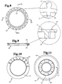
- a recess 25 is concentrically made about hub 15 and leaves a narrow shoulder 26 adjacent the casing. From the free edge, which delimits the shoulder laterally, e.g. three holding lugs 27, arranged at the same mutual angular distance from each other, project into the recess and are designed to retain a digit ring 28, inserted into the recess, which ring is so narrow, that it solely covers window 20 in radial direction.
- Surface 29, which is exposed to this window, is provided with digits 30, which correspond to the number of turns to be indicated, in the circumferential direction of the ring.
- Said surface 29 suitably is delimited at its inner edge by an axially outstanding spacer edge 31 all around, which is designed to distance the surface from the bottom of the recess and prevent/counteract in this way, that the digits are worn off.
- a ring 32 On the other side of digit ring 28 a ring 32, which is somewhat distanced from the inner edge and substantially from the outer edge, projects axially, from which ring in a place suitably corresponding to the 0-adjustment a positioning shoulder 33 projects radially inwards, by means of which shoulder said ring can be allowed to occupy the required starting position, when the ring is mounted in the wheel house.
- Cogs 34 project radially outwards from ring 32 at even intervals and can roughly have a cylindrical shape axially with a uniform link to the outer ring portion and a termination in axial direction at the level of the free axial end of ring 32. In radial direction the cogs can, through approximately a quarter of their radial range, be uniformly connected to ring 32.
- Digit ring 28 and an intermediate wheel 35 interact and the latter is rotatively mounted on axial pin 23 and is supported with its zone of contact on the outer portion of the digit ring.
- the intermediate wheel forms with the digit ring a substantial supplementary shape, which in this case is achieved i.a. by designing the spaces 56 between adjacent cogs 36 as inner semi-cylinders 58 having straight wall extensions 57 outwards and by letting periphery 59 and the wheel essentially follow a cylinder surface, the space between two adjacent cogs of the digit ring in this way always being filled maximally and in this way omissions during the interaction between the digit ring and the intermediate wheel being excluded also after some wear.
- Intermediate wheel cogs 36 suitably are provided with central axial through holes 60, which save material as well as guarantee to a large extent shape stability, deviating sunken thicker portions being counteracted.
- the intermediate wheel is provided with a concentric inner substantially cylinder ring-shaped hole 37, which leaves a bottom 61 at one of the axial ends of the wheel about a pin hole 38. From the inner edge of said bottom 38 two opposite holding shoulders 39 project axially outwards into hole 37, which shoulders at least at their free ends have a smaller mutual distance than the pin diameter, so that a friction locking of the intermediate wheel on the pin can be achieved.
- a decimal ring 40 abuts bottom surface 24 inside the digit ring with a flange 41, which projects outwards in radial direction from one of the ends of a guide cylinder 42, which in axial direction is connected to a concentric sleeve 43 with a larger diameter.
- This sleeve is designed to be slipped onto a protruding top portion 44 of the valve and be secured on this top portion against a relative rotation by providing it with a projection 45 in a tongued and grooved-fashion and in radial direction, which projection can be provided with axial springs 47, which are projecting radially inwards from web 46 of the projection and designed to allow tolerances.
- the transition area between the guide cylinder and the sleeve coincides with a flange 48, which in radial direction projects above the sleeve and the projection and suitably is surrounded by a resilient collar 49, which projects with an angle of preferably about 15° in relation to the longitudinal axis and opens outwards from the flange, which in its mounted position is depressed within the casing space.
- the collar is designed to resiliently snap in below a few locking shoulders 50 at the inner side of the free end of the casing and in this way fasten all the main components of the wheel, namely the house, the digit ring, the intermediate wheel and the decimal ring against each other.
- a driving pin 51 projects from the flange outwards in axial direction and is designed to mesh with a cog space in the intermediate wheel, when this is passed, and in this way to rotate this wheel one graduation, which rotational movement is translated to the digit ring, which is rotated a corresponding graduation in order to indicate a higher or lower entire turn.
- Flange 41 is on its free end surface provided with a numbering all around, which usually comprises the digits 0-9, which correspond to ten decimals of an entire turn. Also, flange 41 is like the digit ring provided with a preferably outer spacer ring 52 all around, which prevents/counteracts a wearing off of the indicating surface.
- the open area between the casing and the collar outside the intermediate wheel can be covered by a shape-complementary protective device 53, which by means of a small flange 54 as an insertion delimitation can abut the collar.
- the wheel according to the present invention is to be mounted on e.g. a valve top piece and to be fastened by means of a screw having the design described above.
- decimal indicating device 40 When pin 51 on decimal indicating device 40 passes intermediate wheel 35, it enters into a cog space 56 and rotates exactly one graduation. This rotational movement is translated to full turn indicating device 28, which always with a cog 34 meshes with intermediate wheel 35. Said graduation corresponds to the angular or peripherical distance between two adjacent digits 30 on surface 29 and consequently full turn indicating device 28 is quickly and reliably fed to the following digit, which over a displacement distance which is as short as possible appears in its entirety.
Landscapes
- Engineering & Computer Science (AREA)
- General Engineering & Computer Science (AREA)
- Mechanical Engineering (AREA)
- Physics & Mathematics (AREA)
- General Physics & Mathematics (AREA)
- Automation & Control Theory (AREA)
- Indication Of The Valve Opening Or Closing Status (AREA)
- Magnetically Actuated Valves (AREA)
- Valve-Gear Or Valve Arrangements (AREA)
- Quick-Acting Or Multi-Walled Pipe Joints (AREA)
- Mechanically-Actuated Valves (AREA)
- Lift Valve (AREA)
- Platform Screen Doors And Railroad Systems (AREA)
- Duct Arrangements (AREA)
- Tires In General (AREA)
Abstract
Description
Claims (10)
- A wheel (1) for e.g. valves, designed to adjust a heating and cooling system etc., which comprises a house (2) having means to indicate the position of e.g. a valve body, to show full turns as well as portions of a turn, which means comprise two or several rotary elements (28;40), which interact with each other but each one of which provides its own indication, one element (40) thereof providing a rotary flexible decimal indication, whereas the other element (28) is influenced by said one element on one occasion per one completed turn to indicate one full turn, characterized in that said decimal indicating element (40) is designed to, via a driver (51) fastened to said element, once per completed turn influence with a graduation a radially outwardly positioned intermediate wheel (35), which in its turn is designed to thereby influence a radially inwardly positioned digit ring (28), which constitutes said other element, in order to indicate a higher or lower full turn.
- A wheel according to claim 1, characterized in that the wheel house (2) , which suitably is produced by injection molding a plastic material or die-casting aluminum and which preferably is star-shaped with four blunt wings (3) and a substantially circular-cylindrical casing (4), which connects the bases of said wings, in that the wings and the casing extend axially from the face (5) of the house to its rear side (6), which is open and in that the interior of the casing and the wings is hollow.
- A wheel according to claim 1 or 2, characterized in that on the face (5) of the house there suitably are use symbols (7), which were stamped, when the wheel was produced, as well as a central hole (8), e.g. a recess (9), designed to recieve a marking plate (10), which by means of a pin (11) is fastened in spindle screw (12) through friction locking in a hole (13) in the screw head (14) and in that also said pin (11) is provided with an axially through hole (55), designed to recieve a tool, by means of which the valve can be preliminarily adjusted without disassembly.
- A wheel according to any of claims 1-3, characterized in that the central part of the wheel concentrically is surrounded by a hub (15), which in axial direction is somewhat shorter than the wings and the casing and is provided with an inner grooving or the like all around (16), which matches a corresponding outer grooving or the like (17) on a spindle end (18) in order to prevent a relative rotation between these parts and/or in that between the base of awing or the hub (15) in the face of the wheel house an axially through recess (19) is made, which is subdivided into a window (20), designed to indicate a full turn and a window (21) designed for portions of a turn and in that said recess preferably is T-shaped, the vertical portion thereof constituting one of the windows (20) and the cross portion thereof constituting the other window (21), in which an indication of a larger measuring range is required.
- A wheel according to claim 4, characterized in that the wing base, which is radially connected to said recess (19), is not like the rest of the wing bases delimited by an arc-shaped casing portion, but the casing is within this area introduced into said wing in order to substantially follow the wing walls roughly parallelly at a distance and then form an approximately quarter-circle (22) with an axial pin (23) as a center of curvature, which axial pin projects outwards from the rear side of the face of the house from an area adjacent the projected circular continuation of the casing and has a length, which roughly corresponds to half the length of the casing.
- A wheel according to claim 4, characterized in that in the bottom surface (24) of the area, which is surrounded by the casing, a recess (25) is concentrically made around the hub (15), which recess leaves a narrow shoulder (26) close to the casing, in that from the free edge, which delimits the shoulder laterally e.g. three holding lugs or the like (27), arranged at the same mutual angular distance, project into the recess and are designed to retain the digit ring (28), which is mounted in the recess and is so narrow, that it solely in radial direction covers said one window (20), in that the surface (29), which is exposed to this window, is provided with digits (30) in the circumferential direction of the ring, which correspond to the number of turns, which are to be indicated, and in that said surface (29) at the inner edge suitably is delimited by means of an axially projecting spacer edge all around (31), the purpose of which is to space the surface from the bottom of the recess and to prevent/counteract in this way that said digits are worn off.
- A wheel according to claim 6, characterized in that on the other side of the digit ring (28) a ring (32), which suitably is spaced somewhat from the inner edge and substantially from the outer edge, projects in axial direction, from which ring in a location, which suitably corresponds to the 0-adjustement, a positioning shoulder (33) projects radially inwards, by means of which the ring can be allowed, when the ring is mounted in the wheel house, to occupy the required starting position, in that radially outwards from the ring (32) cogs (34) project with even spaces therebetween, which cogs suitably are roughly cylinder-shaped in axial direction with a uniform transition into the outer ring portion and a termination in axial direction at the level of the free axial end of the ring (32) and in that said cogs in radial direction through approximately a quarter of their circumference are uniformly connected to the ring (32).
- A wheel according to claim 7, characterized in that said intermediate wheel (35) interacts with the digit ring (28) and is rotatively mounted on the axial pin (23) and is supported with its zone of contact on the outer portion of the digit ring, in that the intermediate wheel has ashape, which is complementary to a large extent as regards the digit ring, mainly because the shape of the spaces (56) between adjacent cogs (36) are inner half-cylinders (58) with straight wall extensions (57) outwards and because the periphery (59) of the wheel substantially follows a cylinder surface, in that the intermediate wheel cogs (36) suitably are provided with central axially through holes (60), in that the intermediate wheel is provided with a concentric inner substantially cylinder ring-shaped hole (37), leaving a bottom (61) at one axial end of the wheel around a pin hole (38), and in that from the inner edge of said bottom (38) two opposite holding shoulders (39) project axially outwards into the hole (37) and at least at their free ends have a smaller mutual distance from each other than the pin diameter in order to attain a friction locking of the intermediate wheel on the pin.
- A wheel according to claim 8, characterized in that said decimal ring (40) abuts the bottom surface (24) inside the digit ring with a flange (41), which projects in axial direction from one end of a guide cylinder (42), which in axial direction is connected to a concentric sleeve (43) with a larger diameter, which sleeve is designed to be slipped on a projecting top piece (44) of the valve and is secured on it against a relative rotation, because it is provided with a tongued and grooved-like projection (45) in radial direction, which projection preferably has axial springs (47), which project radially inwards from the web (46) of the projection, in order to recieve tolerances, in that the transition area between the guide cylinder and the sleeve coincides with a flange (48), which in radial direction projects above the sleeve and the projection and suitably is surrounded by a resilient collar (49), which extends with an angle of approximately 15° in relation to the longitudinal axis and opens outwards from the flange, which in its mounted position is recessed within the casing space, and in that the collar is designed to resiliently snap in under a few locking shoulders (50) at the inner side of the free end of the casing and in this way fasten against each other all the main parts of the wheel, which comprise the house, the digit ring , the intermediate wheel and the decimal ring.
- A wheel according to claim 9, characterized in that from a location close to the periphery of the flange (41) said driver pin (51) projects from the flange in axial direction and is designed to mesh with a cog space of the intermediate wheel, when it is passing the cog space, and in this way to rotate this wheel one graduation, which rotational movement is designed to be translated to the digit ring, which is rotated a corresponding graduation in order to indicate a higher or lower full turn, in that the flange (41) on its free end surface is provided with a numbering all around, comprising e.g. digits 0-9, corresponding to ten decimals of a full turn, in that the flange 41 in a similar way as the digit ring is provided with a preferably outer spacer ring (52) all around in order to prevent/counteract that the indicating surface will be worn off, and in that the open area between the casing and the collar outside the intermediate wheel is covered by a shape-complementary protection element (53), which with e.g. a small flange (54) as an insertion delimitation is designed to contact the collar.
Applications Claiming Priority (3)
| Application Number | Priority Date | Filing Date | Title |
|---|---|---|---|
| SE9300642 | 1993-02-25 | ||
| SE9300642A SE500023C2 (en) | 1993-02-25 | 1993-02-25 | Steering wheel with means for position indication |
| PCT/SE1994/000106 WO1994019636A1 (en) | 1993-02-25 | 1994-02-10 | Valve wheel |
Publications (2)
| Publication Number | Publication Date |
|---|---|
| EP0686242A1 EP0686242A1 (en) | 1995-12-13 |
| EP0686242B1 true EP0686242B1 (en) | 1998-04-15 |
Family
ID=20389039
Family Applications (1)
| Application Number | Title | Priority Date | Filing Date |
|---|---|---|---|
| EP94908536A Expired - Lifetime EP0686242B1 (en) | 1993-02-25 | 1994-02-10 | Valve wheel |
Country Status (10)
| Country | Link |
|---|---|
| US (1) | US5769118A (en) |
| EP (1) | EP0686242B1 (en) |
| AT (1) | ATE165145T1 (en) |
| AU (1) | AU6158894A (en) |
| DE (1) | DE69409639T2 (en) |
| DK (1) | DK0686242T3 (en) |
| ES (1) | ES2118391T3 (en) |
| FI (1) | FI103145B (en) |
| SE (1) | SE500023C2 (en) |
| WO (1) | WO1994019636A1 (en) |
Families Citing this family (23)
| Publication number | Priority date | Publication date | Assignee | Title |
|---|---|---|---|---|
| US6912968B2 (en) * | 2003-03-04 | 2005-07-05 | Hunter Fan Company | Schedule indicator |
| US6871665B2 (en) * | 2003-09-03 | 2005-03-29 | Be Intellectual Property, Inc. | Aircraft oxygen valve having knob with distinctive position indicator |
| SE531014C2 (en) * | 2006-06-12 | 2008-11-18 | Tour & Andersson Ab | Cone with adjustable KVS and constant characteristic |
| CN101021287B (en) * | 2006-08-24 | 2010-06-23 | 中山市银龙卫浴有限公司 | Water valve hand wheel and producing technology thereof |
| DE102006047878A1 (en) * | 2006-10-10 | 2008-04-24 | Danfoss A/S | flow adjustment |
| US7779775B2 (en) * | 2008-03-14 | 2010-08-24 | Hunter Fan Company | Schedule indicator |
| USD734189S1 (en) * | 2012-07-11 | 2015-07-14 | Cynthia L. Ring | Counting device |
| DK177597B1 (en) * | 2012-09-17 | 2013-11-11 | Flowcon Internat Aps | Detachable grip for adjusting a valve and unit comprising a detachable grip and valve |
| ES2505315B1 (en) * | 2013-03-08 | 2015-09-25 | Válvulas Arco, S.L. | PERFECTED THREE-WAY VALVE STRUCTURE |
| PL224342B1 (en) * | 2014-06-18 | 2016-12-30 | Zetkama Spółka Akcyjna | Balancing valve |
| US9447897B2 (en) * | 2014-12-02 | 2016-09-20 | Vir Valvoindustria Ing. Rizzio S.P.A. | Handwheel for hydraulic valve provided with opening level indicator |
| KR101819921B1 (en) * | 2016-10-10 | 2018-01-18 | 삼성전자주식회사 | Valve shutter |
| US10132345B2 (en) * | 2017-01-18 | 2018-11-20 | Hanwit Precision Industries Ltd. | Fastening device |
| US10487866B2 (en) * | 2017-01-18 | 2019-11-26 | Hanwit Precision Industries Ltd. | Fastening device |
| JP6892783B2 (en) * | 2017-04-19 | 2021-06-23 | 株式会社清水合金製作所 | Rotary valve with minute opening display function and minute opening adjustment method |
| LU100977B1 (en) * | 2018-11-06 | 2020-05-06 | Luxembourg Patent Co | Enhanced handwheel cap |
| HUE054522T2 (en) * | 2019-02-28 | 2021-09-28 | Fluehs Drehtechnik Gmbh | Valve top section for sanitary fittings |
| CN110617363B (en) * | 2019-09-11 | 2024-12-20 | 泉州市里维斯精密五金有限公司 | An independent and detachable gear rotating core |
| JP7409591B2 (en) * | 2020-07-30 | 2024-01-09 | Smc株式会社 | flow control valve |
| JP7596906B2 (en) * | 2021-04-12 | 2024-12-10 | Smc株式会社 | Flow Control Valve |
| KR102318429B1 (en) * | 2021-06-18 | 2021-10-27 | (주) 폴리텍 | Safety opening and closing valve |
| EP4160067A1 (en) * | 2021-09-30 | 2023-04-05 | IMI Hydronic Engineering International SA | A valve handwheel and a valve arrangement comprising such a valve handwheel |
| DE102023105874B4 (en) * | 2023-03-09 | 2026-04-23 | Hansgrohe Se | Operating device for actuating a valve and valve |
Family Cites Families (7)
| Publication number | Priority date | Publication date | Assignee | Title |
|---|---|---|---|---|
| US2767681A (en) * | 1953-05-04 | 1956-10-23 | J A Zurn Mfg Co | Indicating means |
| US2752878A (en) * | 1955-04-19 | 1956-07-03 | Tejax Engineering Corp | Gauge for calibrating rotary movement |
| US3450091A (en) * | 1967-03-20 | 1969-06-17 | Spectrol Electronics Corp | Multi-turn indicator dial system |
| DE1775594C3 (en) * | 1968-08-30 | 1975-04-17 | Robert Bosch Gmbh, 7000 Stuttgart | Adjustment device for a spindle with a position indicator |
| SE448651B (en) * | 1985-09-18 | 1987-03-09 | Tour & Andersson Ab | Position adjustment device with indicator for valve wheel |
| US4893582A (en) * | 1986-11-19 | 1990-01-16 | Teleflex Incorporated | Deck box valve operator and position indicator assembly |
| US5316040A (en) * | 1993-03-26 | 1994-05-31 | Townsend Robert L | Valve alignment tool |
-
1993
- 1993-02-25 SE SE9300642A patent/SE500023C2/en not_active IP Right Cessation
-
1994
- 1994-02-10 AT AT94908536T patent/ATE165145T1/en not_active IP Right Cessation
- 1994-02-10 AU AU61588/94A patent/AU6158894A/en not_active Abandoned
- 1994-02-10 DK DK94908536T patent/DK0686242T3/en active
- 1994-02-10 ES ES94908536T patent/ES2118391T3/en not_active Expired - Lifetime
- 1994-02-10 US US08/491,912 patent/US5769118A/en not_active Expired - Fee Related
- 1994-02-10 WO PCT/SE1994/000106 patent/WO1994019636A1/en not_active Ceased
- 1994-02-10 DE DE69409639T patent/DE69409639T2/en not_active Expired - Fee Related
- 1994-02-10 EP EP94908536A patent/EP0686242B1/en not_active Expired - Lifetime
-
1995
- 1995-08-25 FI FI954000A patent/FI103145B/en active
Also Published As
| Publication number | Publication date |
|---|---|
| SE9300642L (en) | 1994-03-21 |
| FI954000A0 (en) | 1995-08-25 |
| AU6158894A (en) | 1994-09-14 |
| SE9300642D0 (en) | 1993-02-25 |
| FI103145B1 (en) | 1999-04-30 |
| US5769118A (en) | 1998-06-23 |
| FI103145B (en) | 1999-04-30 |
| DE69409639T2 (en) | 1998-11-05 |
| DK0686242T3 (en) | 1999-02-22 |
| ATE165145T1 (en) | 1998-05-15 |
| FI954000A7 (en) | 1995-08-25 |
| SE500023C2 (en) | 1994-03-21 |
| DE69409639D1 (en) | 1998-05-20 |
| WO1994019636A1 (en) | 1994-09-01 |
| EP0686242A1 (en) | 1995-12-13 |
| ES2118391T3 (en) | 1998-09-16 |
Similar Documents
| Publication | Publication Date | Title |
|---|---|---|
| US5769118A (en) | Position indicating valve wheel | |
| US5067758A (en) | Lock handle assembly with limited angular movement | |
| CA2103955C (en) | Front loaded cylinder for door lockset | |
| CA2084727C (en) | Condiment grinder | |
| US5335950A (en) | Door lockset with spindle bearing | |
| EP0583952B1 (en) | Lever operated door lock assembly | |
| US6070442A (en) | Lockout device | |
| JPH06506638A (en) | handheld machine tool | |
| EP0374453A3 (en) | Steering wheel lock | |
| US4287735A (en) | Key assembly for coded security system | |
| GB2150645A (en) | Dispensing pump | |
| US5664447A (en) | Valve lockout | |
| US5730176A (en) | Single-control mixing valve with pivotal casing | |
| US11618316B2 (en) | Lockable cap assembly for a fuel filler pipe | |
| US2951358A (en) | Dial and spindle assembly | |
| CN210888370U (en) | Square shaft mounting structure, handle core subassembly and lock | |
| DE60008167D1 (en) | Electromagnetic security lock | |
| US3902519A (en) | Operation lock for fire hydrants | |
| US2302654A (en) | Bicycle lock | |
| GB2056685A (en) | Trimmer for a motor-boat | |
| US3802231A (en) | Combination lock | |
| CN223563607U (en) | Water mixing valve | |
| JPH0446450Y2 (en) | ||
| US1484473A (en) | Cylinder lock | |
| JPH0541790Y2 (en) |
Legal Events
| Date | Code | Title | Description |
|---|---|---|---|
| PUAI | Public reference made under article 153(3) epc to a published international application that has entered the european phase |
Free format text: ORIGINAL CODE: 0009012 |
|
| 17P | Request for examination filed |
Effective date: 19950816 |
|
| AK | Designated contracting states |
Kind code of ref document: A1 Designated state(s): AT BE CH DE DK ES FR GB GR IE IT LI LU MC NL PT |
|
| GRAG | Despatch of communication of intention to grant |
Free format text: ORIGINAL CODE: EPIDOS AGRA |
|
| GRAG | Despatch of communication of intention to grant |
Free format text: ORIGINAL CODE: EPIDOS AGRA |
|
| GRAH | Despatch of communication of intention to grant a patent |
Free format text: ORIGINAL CODE: EPIDOS IGRA |
|
| 17Q | First examination report despatched |
Effective date: 19970721 |
|
| GRAH | Despatch of communication of intention to grant a patent |
Free format text: ORIGINAL CODE: EPIDOS IGRA |
|
| GRAA | (expected) grant |
Free format text: ORIGINAL CODE: 0009210 |
|
| AK | Designated contracting states |
Kind code of ref document: B1 Designated state(s): AT BE CH DE DK ES FR GB GR IE IT LI LU MC NL PT |
|
| PG25 | Lapsed in a contracting state [announced via postgrant information from national office to epo] |
Ref country code: NL Free format text: LAPSE BECAUSE OF FAILURE TO SUBMIT A TRANSLATION OF THE DESCRIPTION OR TO PAY THE FEE WITHIN THE PRESCRIBED TIME-LIMIT Effective date: 19980415 Ref country code: LI Free format text: LAPSE BECAUSE OF FAILURE TO SUBMIT A TRANSLATION OF THE DESCRIPTION OR TO PAY THE FEE WITHIN THE PRESCRIBED TIME-LIMIT Effective date: 19980415 Ref country code: IT Free format text: LAPSE BECAUSE OF FAILURE TO SUBMIT A TRANSLATION OF THE DESCRIPTION OR TO PAY THE FEE WITHIN THE PRE;WARNING: LAPSES OF ITALIAN PATENTS WITH EFFECTIVE DATE BEFORE 2007 MAY HAVE OCCURRED AT ANY TIME BEFORE 2007. THE CORRECT EFFECTIVE DATE MAY BE DIFFERENT FROM THE ONE RECORDED.SCRIBED TIME-LIMIT Effective date: 19980415 Ref country code: GR Free format text: LAPSE BECAUSE OF NON-PAYMENT OF DUE FEES Effective date: 19980415 Ref country code: CH Free format text: LAPSE BECAUSE OF FAILURE TO SUBMIT A TRANSLATION OF THE DESCRIPTION OR TO PAY THE FEE WITHIN THE PRESCRIBED TIME-LIMIT Effective date: 19980415 Ref country code: BE Free format text: LAPSE BECAUSE OF FAILURE TO SUBMIT A TRANSLATION OF THE DESCRIPTION OR TO PAY THE FEE WITHIN THE PRESCRIBED TIME-LIMIT Effective date: 19980415 Ref country code: AT Free format text: LAPSE BECAUSE OF FAILURE TO SUBMIT A TRANSLATION OF THE DESCRIPTION OR TO PAY THE FEE WITHIN THE PRESCRIBED TIME-LIMIT Effective date: 19980415 |
|
| REF | Corresponds to: |
Ref document number: 165145 Country of ref document: AT Date of ref document: 19980515 Kind code of ref document: T |
|
| REG | Reference to a national code |
Ref country code: CH Ref legal event code: EP |
|
| REF | Corresponds to: |
Ref document number: 69409639 Country of ref document: DE Date of ref document: 19980520 |
|
| ET | Fr: translation filed | ||
| PG25 | Lapsed in a contracting state [announced via postgrant information from national office to epo] |
Ref country code: PT Free format text: LAPSE BECAUSE OF FAILURE TO SUBMIT A TRANSLATION OF THE DESCRIPTION OR TO PAY THE FEE WITHIN THE PRESCRIBED TIME-LIMIT Effective date: 19980715 |
|
| REG | Reference to a national code |
Ref country code: IE Ref legal event code: FG4D Free format text: 79847 |
|
| NLV1 | Nl: lapsed or annulled due to failure to fulfill the requirements of art. 29p and 29m of the patents act | ||
| REG | Reference to a national code |
Ref country code: ES Ref legal event code: FG2A Ref document number: 2118391 Country of ref document: ES Kind code of ref document: T3 |
|
| REG | Reference to a national code |
Ref country code: CH Ref legal event code: PL |
|
| PG25 | Lapsed in a contracting state [announced via postgrant information from national office to epo] |
Ref country code: LU Free format text: LAPSE BECAUSE OF NON-PAYMENT OF DUE FEES Effective date: 19990210 Ref country code: IE Free format text: LAPSE BECAUSE OF NON-PAYMENT OF DUE FEES Effective date: 19990210 |
|
| PLBE | No opposition filed within time limit |
Free format text: ORIGINAL CODE: 0009261 |
|
| STAA | Information on the status of an ep patent application or granted ep patent |
Free format text: STATUS: NO OPPOSITION FILED WITHIN TIME LIMIT |
|
| REG | Reference to a national code |
Ref country code: DK Ref legal event code: T3 |
|
| 26N | No opposition filed | ||
| PG25 | Lapsed in a contracting state [announced via postgrant information from national office to epo] |
Ref country code: MC Free format text: LAPSE BECAUSE OF NON-PAYMENT OF DUE FEES Effective date: 19990831 |
|
| PGFP | Annual fee paid to national office [announced via postgrant information from national office to epo] |
Ref country code: FR Payment date: 19991208 Year of fee payment: 7 |
|
| PGFP | Annual fee paid to national office [announced via postgrant information from national office to epo] |
Ref country code: DE Payment date: 19991210 Year of fee payment: 7 |
|
| PGFP | Annual fee paid to national office [announced via postgrant information from national office to epo] |
Ref country code: GB Payment date: 19991215 Year of fee payment: 7 |
|
| PGFP | Annual fee paid to national office [announced via postgrant information from national office to epo] |
Ref country code: DK Payment date: 20000124 Year of fee payment: 7 |
|
| PGFP | Annual fee paid to national office [announced via postgrant information from national office to epo] |
Ref country code: ES Payment date: 20000216 Year of fee payment: 7 |
|
| PG25 | Lapsed in a contracting state [announced via postgrant information from national office to epo] |
Ref country code: GB Free format text: LAPSE BECAUSE OF NON-PAYMENT OF DUE FEES Effective date: 20010210 Ref country code: DK Free format text: LAPSE BECAUSE OF NON-PAYMENT OF DUE FEES Effective date: 20010210 |
|
| PG25 | Lapsed in a contracting state [announced via postgrant information from national office to epo] |
Ref country code: ES Free format text: LAPSE BECAUSE OF NON-PAYMENT OF DUE FEES Effective date: 20010212 |
|
| GBPC | Gb: european patent ceased through non-payment of renewal fee |
Effective date: 20010210 |
|
| REG | Reference to a national code |
Ref country code: DK Ref legal event code: EBP |
|
| PG25 | Lapsed in a contracting state [announced via postgrant information from national office to epo] |
Ref country code: FR Free format text: LAPSE BECAUSE OF NON-PAYMENT OF DUE FEES Effective date: 20011031 |
|
| REG | Reference to a national code |
Ref country code: FR Ref legal event code: ST |
|
| PG25 | Lapsed in a contracting state [announced via postgrant information from national office to epo] |
Ref country code: DE Free format text: LAPSE BECAUSE OF NON-PAYMENT OF DUE FEES Effective date: 20011201 |
|
| REG | Reference to a national code |
Ref country code: ES Ref legal event code: FD2A Effective date: 20021116 |