EP0685738B1 - Reconfigurable pneumatic control for split/splitless injection - Google Patents
Reconfigurable pneumatic control for split/splitless injection Download PDFInfo
- Publication number
- EP0685738B1 EP0685738B1 EP95101256A EP95101256A EP0685738B1 EP 0685738 B1 EP0685738 B1 EP 0685738B1 EP 95101256 A EP95101256 A EP 95101256A EP 95101256 A EP95101256 A EP 95101256A EP 0685738 B1 EP0685738 B1 EP 0685738B1
- Authority
- EP
- European Patent Office
- Prior art keywords
- control
- split
- setpoint
- values
- output
- Prior art date
- Legal status (The legal status is an assumption and is not a legal conclusion. Google has not performed a legal analysis and makes no representation as to the accuracy of the status listed.)
- Expired - Lifetime
Links
- 238000002347 injection Methods 0.000 title claims description 58
- 239000007924 injection Substances 0.000 title claims description 58
- 239000012530 fluid Substances 0.000 claims description 35
- 238000010926 purge Methods 0.000 claims description 28
- 230000033228 biological regulation Effects 0.000 claims description 11
- 238000000926 separation method Methods 0.000 claims description 9
- 238000013375 chromatographic separation Methods 0.000 claims description 4
- 230000000694 effects Effects 0.000 claims description 4
- 239000012159 carrier gas Substances 0.000 description 31
- 239000007789 gas Substances 0.000 description 23
- 238000004587 chromatography analysis Methods 0.000 description 12
- 239000000203 mixture Substances 0.000 description 11
- 238000000034 method Methods 0.000 description 8
- 230000004044 response Effects 0.000 description 8
- RHPUJHQBPORFGV-UHFFFAOYSA-N 4-chloro-2-methylphenol Chemical compound CC1=CC(Cl)=CC=C1O RHPUJHQBPORFGV-UHFFFAOYSA-N 0.000 description 5
- 230000007704 transition Effects 0.000 description 5
- 238000004458 analytical method Methods 0.000 description 3
- XKRFYHLGVUSROY-UHFFFAOYSA-N Argon Chemical compound [Ar] XKRFYHLGVUSROY-UHFFFAOYSA-N 0.000 description 2
- IJGRMHOSHXDMSA-UHFFFAOYSA-N Atomic nitrogen Chemical compound N#N IJGRMHOSHXDMSA-UHFFFAOYSA-N 0.000 description 2
- 239000012491 analyte Substances 0.000 description 2
- 238000003965 capillary gas chromatography Methods 0.000 description 2
- 230000006870 function Effects 0.000 description 2
- 239000007788 liquid Substances 0.000 description 2
- 230000014759 maintenance of location Effects 0.000 description 2
- VNWKTOKETHGBQD-UHFFFAOYSA-N methane Chemical compound C VNWKTOKETHGBQD-UHFFFAOYSA-N 0.000 description 2
- 230000001105 regulatory effect Effects 0.000 description 2
- 239000000126 substance Substances 0.000 description 2
- 238000012546 transfer Methods 0.000 description 2
- 229910052786 argon Inorganic materials 0.000 description 1
- 238000003491 array Methods 0.000 description 1
- 230000008901 benefit Effects 0.000 description 1
- 238000009835 boiling Methods 0.000 description 1
- 230000008859 change Effects 0.000 description 1
- 238000006243 chemical reaction Methods 0.000 description 1
- 238000004891 communication Methods 0.000 description 1
- 230000003750 conditioning effect Effects 0.000 description 1
- 239000000470 constituent Substances 0.000 description 1
- 230000001276 controlling effect Effects 0.000 description 1
- 238000013479 data entry Methods 0.000 description 1
- 230000003247 decreasing effect Effects 0.000 description 1
- 238000001514 detection method Methods 0.000 description 1
- 239000001307 helium Substances 0.000 description 1
- 229910052734 helium Inorganic materials 0.000 description 1
- SWQJXJOGLNCZEY-UHFFFAOYSA-N helium atom Chemical compound [He] SWQJXJOGLNCZEY-UHFFFAOYSA-N 0.000 description 1
- 239000001257 hydrogen Substances 0.000 description 1
- 229910052739 hydrogen Inorganic materials 0.000 description 1
- 125000004435 hydrogen atom Chemical class [H]* 0.000 description 1
- 230000006872 improvement Effects 0.000 description 1
- 230000000977 initiatory effect Effects 0.000 description 1
- 230000007246 mechanism Effects 0.000 description 1
- 238000012986 modification Methods 0.000 description 1
- 230000004048 modification Effects 0.000 description 1
- 229910052757 nitrogen Inorganic materials 0.000 description 1
- 238000004886 process control Methods 0.000 description 1
- 238000011084 recovery Methods 0.000 description 1
- 230000035945 sensitivity Effects 0.000 description 1
Images




Classifications
-
- G—PHYSICS
- G01—MEASURING; TESTING
- G01N—INVESTIGATING OR ANALYSING MATERIALS BY DETERMINING THEIR CHEMICAL OR PHYSICAL PROPERTIES
- G01N30/00—Investigating or analysing materials by separation into components using adsorption, absorption or similar phenomena or using ion-exchange, e.g. chromatography or field flow fractionation
- G01N30/02—Column chromatography
- G01N30/04—Preparation or injection of sample to be analysed
- G01N30/24—Automatic injection systems
-
- G—PHYSICS
- G01—MEASURING; TESTING
- G01N—INVESTIGATING OR ANALYSING MATERIALS BY DETERMINING THEIR CHEMICAL OR PHYSICAL PROPERTIES
- G01N30/00—Investigating or analysing materials by separation into components using adsorption, absorption or similar phenomena or using ion-exchange, e.g. chromatography or field flow fractionation
- G01N30/02—Column chromatography
- G01N30/26—Conditioning of the fluid carrier; Flow patterns
- G01N30/28—Control of physical parameters of the fluid carrier
- G01N30/32—Control of physical parameters of the fluid carrier of pressure or speed
-
- G—PHYSICS
- G01—MEASURING; TESTING
- G01N—INVESTIGATING OR ANALYSING MATERIALS BY DETERMINING THEIR CHEMICAL OR PHYSICAL PROPERTIES
- G01N30/00—Investigating or analysing materials by separation into components using adsorption, absorption or similar phenomena or using ion-exchange, e.g. chromatography or field flow fractionation
- G01N30/02—Column chromatography
- G01N30/04—Preparation or injection of sample to be analysed
- G01N30/06—Preparation
- G01N30/12—Preparation by evaporation
- G01N2030/126—Preparation by evaporation evaporating sample
Definitions
- the present invention relates to chromatographic analysis systems and, more particularly, to an apparatus and method for control of the fluid flow through a chromatographic analysis system that operates in split/splitless injection mode configurations.
- chromatographic techniques have become important tools in the identification of chemical sample components.
- the basic mechanism underlying chromatographic analysis is the separation of a sample chemical mixture into individual components by injecting the sample into a carrier fluid (preferably a carrier gas) and transporting the mixture through a specially prepared separation column.
- a carrier fluid preferably a carrier gas
- EPC Electronic pressure control
- An example of a modern electronic pressure control system is disclosed, for example, in Klein, et al., U.S. Patent No. 4,994,096 and United States Patent No. 5,108,466 .
- Klein et al. also disclose electronic pressure control of fluids in " CGC Using a Programmable Electronic Pressure Controller," J. High Resolution Chromatography 13:361, May 1990 .
- a conventional gas chromatographic system may be constructed to include a particular type of injection port known as a split/splitless inlet capable of operation in either of two injection modes.
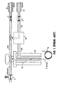
- Figure 1 shows the flow paths of the carrier gas flow during a splitless injection;
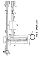
- Figure 2 shows the flow paths of the carrier gas flow during split injection modes.
- carrier gas is passed through a flow controller (14) to the split/splitless injection port (12) where the injected sample mixes with the carrier gas and the mixture is directed into a separation column (18).
- the carrier gas flow also passes to the septum purge line (12A) while any non-analyzed mixture flow is blocked in a split line (12B) by setting a three-way valve (20) to block split flow.
- the three-way valve (20) can be set to pass split vent gas flow through a split vent line (12C) to a pressure controller (24) and a split vent (25), while the septum purge flow is passed to a septum purge flow controller (21) and a septum purge vent (22).
- the temperature of the column (18) is controlled according to known techniques so that the sample will separate into its components.
- the carrier gas (containing the sample) exits the column (18)
- the presence of one or more sample constituent components is detected by a detector (not shown).
- the pressure of the carrier gas entering the injection port (12) is controlled by the pressure controller (24) in response to an appropriate control signal.
- the split/splitless inlet is typically operated in split or splitless injection modes with control of the column flow effected by back pressure regulation.
- the inlet (12) is first configured such that only a portion of the carrier gas that enters the inlet (12) can also enter the column (18), while the remainder "sweeps" the top of the inlet (12) and exits through the septum purge line (12A).
- the purge control valve (20) must be set so that the carrier gas that enters the inlet liner (12L) can only exit the split/splitless inlet into the column (18).
- the sample While the purge gas continues to sweep the top of the inlet (12) and passes through the septum purge line (12A), the sample may be injected into the inlet liner (12L) and vaporized. Under ideal conditions, the vaporized sample is expected to transfer to the column during an initial "hold time" (typically 30 to 90 seconds).
- the purge valve (20) is opened (as shown in Figure 2 ), and any residual carrier gas/sample mixture remaining in the inlet liner (12L) is swept out through the split vent line (12B).
- splitless injection sample transfer from the inlet liner (12L) to the separation column (18) is not wholly effective unless the entire sample is vaporized rapidly and uniformly into a vapor cloud that is available in the inlet liner (12L) during the hold time.
- Splitless injection is hampered when the sample is not sufficiently vaporized, or if sample components are lost when the most volatile components of the sample vaporize rapidly, expand to fill the liner (12L), and are swept away. This phenomena (known as sample discrimination) is worsened when working quantitatively with sensitive analytes, wide boiling range mixtures, or when increasing the sample volume for greater sensitivity.
- a "high-flow" splitless injection (wherein the carrier gas entering the inlet is maintained at a high flow rate, and both the septum purge line and the split vent line are active) causes the flow over the top of the inlet to attract some of the sample into the purge line, with an undesireable loss of sample from the column, and a lowered total area count.
- a lower total flow rate would lessen this phenomena, but such a flow rate is impractical for effecting capillary separation because the purge flow is insufficient and the operation of the pressure controller (24) is problematic.
- the pressure program is set to effect a "pressure pulse" whereby the column head pressure is increased prior to injection, then rapidly reduced to a setpoint best suited for column flow.
- the time required to increase the pressure during such transitions is more than desireable, and the column head pressure does not increase (i.e., "pulse") as rapidly and effectively as desired. Sample discrimination can result.
- a three-way valve (20) and its associated drive circuitry contributes to the greater parts count and the increased cost of a split/splitless inlet.
- Three-way valves are also not as reliable as would be desired.
- JP-A-05288373 discloses a gas chromatographic apparatus having an injection port for a column.
- the injection port has an inlet, a split line and a septum purge line.
- the apparatus comprises a system controller for selecting split and splitless modes, a control valve for the input line and a control valve for the split line.
- the split ratio can be controlled to a preliminary specified value and subsequently to a reduced value.
- US-A-5,163,979 relates to a pressure-programmable gas chromatograph system with split and splitless operational modes.
- the system includes an injector for a column, with a conduit for split-injection and a purge line.
- a system controller is used for selecting the mode of operation.
- a programmable-pressure control of the system uses an oscillating back pressure regulator in the conduit.
- the object of the invention to provide an apparatus and a method for performing a chromatographic separation of a sample in a system that is operable in split/splitless injection modes, wherein the carrier fluid flow is more accurately and reliably controlled, to afford an increased total area count, with use of a simpler and less-expensive arrangement of components.
- the preferred embodiments of the contemplated gas chromatographic analysis system accomplish more accurate and repeatable control of the column fluid flow during transitions between split and splitless modes, and during operation in the splitless mode.
- the apparatus and methods of the present invention may be employed to improve the control of the flow of a variety of compressible fluids in an analytical chromatographic system.
- Such fluids are intended to include gases, liquids, multiple component gases and liquids, and mixtures thereof capable of regulated flow.
- Gases are the preferred fluids according to the practice of the present invention, and therefore the following description of the invention will be directed to a gas chromatographic analytical system. Further, the description herein is directed to certain pneumatic characteristics of the fluid flow, such as pressure.
- the carrier gas may comprise one or more component gases (such as hydrogen, nitrogen, argon, methane, or helium) depending upon the particular chromatographic separation to be performed.
- component gases such as hydrogen, nitrogen, argon, methane, or helium
- a gas chromatographic analysis system may be constructed according to the present invention to include certain components already described with reference to Figures 1 - 2 . Components of like nomenclature and reference numerals are intended to be equivalent.
- the preferred embodiment (100) of Figure 3A is constructed as a keyboard-operated, table-driven gas chromatograph wherein the system configuration and operation, and particularly the operation of the gas streams for the unit's injection and detection systems, can be controlled by use of an input/output device (102) or via a communication line to a remote controller (107) such as a computer workstation, central control station, or another gas chromatograph.
- a remote controller such as a computer workstation, central control station, or another gas chromatograph.
- the operator may perform data entry and control table editing by way of a keyboard (106).
- a status board (108) displays information about the current status of certain systems while the chromatograph is in operation.
- Actual values of certain operating parameters, and system control values are organized into one or more control tables that are created in response to data from the remote controller (107) or (preferably) in response to data input by the operator on the input/output device (102) and to programming and firmware operative in a system controller (109).
- the tables are viewable and editable on a display (104).
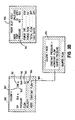
- Figure 3B illustrates examples of a few tables (inlet, column, and mode control tables (150, 160, 170)) as they would be rendered on the display (104). Examples of certain parameters of interest are: column dimensions (162), actual column pressure (163), column pressure setpoint (164), column flow rate (165), and calculated average linear velocity (166), and control mode (168).
- the system controller (109) preferably includes data acquisition, memory, computation, and other process control circuitry suited for initiating and controlling the various functions relative to operation of the gas chromatograph (100), and software and/or firmware pertinent to carrying out the functions and operations indicated in the control tables, and in particular the generation, storage, and editing of the tables indicated on the display (104).
- the gas chromatograph (100) is preferably operable in split and splitless injection modes, with the latter including an optional pulsed splitless mode.
- a mode may be selected by use of the mode table (150) displayed on the input/output device (102).
- a pulsed splitless mode for example, may include a pressure pulse feature, wherein the inlet pressure is increased at the beginning of an analysis and then is reduced to a normal level after selectable delay time.
- regulated carrier gas flow is provided via a inlet flow fluid controller, preferably in the form of a proportional control valve (114), to the split/splitless injection port (12).
- a sample is introduced into the heated inlet (12) where it vaporizes.
- a small amount of the sample/carrier gas mixture enters the column (18) while the majority of the sample/carrier gas mixture is vented out of the split vent (25).
- the split flow/column flow mixture ratio may be set by the operator according to the use of the input/output device (102) or remote controller (107) described above.
- a split line control valve (124) in the form of a bubble-tight shutoff valve (124A) and a proportional valve (124B) is closed during the injection and remains closed while the sample is vaporized and transferred to the column (18).
- the split vent fluid controller is opened and any vapors remaining in the inlet are purged. Purge time and flow rate may be specified by editing the inlet control table (150).
- flow may pass through a combination of a septum purge line (112A) or a split line (112B), or both.
- the conventional three-way purge valve (20) in Figures 1-2 ) is omitted.
- Septum purge flow is directed to the septum purge controller (21), flow restrictor (22), and septum purge vent (23); split vent flow passes directly to the shutoff valve (124A) and proportional control valve (124B), and then to a split vent (25).
- the shutoff valve (124A) is illustrated in the "open" (full flow) position; a "closed" (zero flow) position is optionally selectable, as will be described below.
- the preferred embodiment may be seen to include a reconfigurable fluid control system (110) having a setpoint controller (200) that receives a first sense signal from a first sensor (115) by way of sense line (116A).
- the first sensor (115) is preferably an inlet flow sensor that provides a sense signal representative of the inlet gas flow, and accordingly the setpoint controller (200) is implemented to provide a first setpoint control output value on output line (203).
- the setpoint controller (200) receives a second sense signal from a second sensor (126) by way of sense line (127).
- the second sensor (126) is preferably a gage pressure sensor that provides a sense signal representative of the pressure at a point in the septum purge line (112A), which is indirectly representative of the column head pressure at the head of the column (18). Accordingly the setpoint controller (200) is preferably implemented to provide a second setpoint control output value on output line (204).
- the aforementioned first and second setpoint control output values are determined by the setpoint controller (200) according to pressure and flow control programming in response to one or more parameters and modes selected from the control tables.
- the selection criteria includes the injection mode (split, splitless, or pulsed splitless), and related conditions, such as the onset of an inlet purge during a splitless injection mode.
- other criteria may be used.
- the application of the setpoint control output values by the fluid control system (110) to the inlet control valve (114) and split line control valve (124) is selectably reconfigurable at any time in accordance with the control tables that are currently operative.
- the fluid control system (110) interacts with the system controller (109) to send and receive other data and control signals.
- actual values such as the actual inlet pressure, and setpoint values, such as the column head pressure setpoint, may be provided to the system controller (109) for display on the input output device (102).
- Each of the first and second setpoint control output values on respective lines (203, 204) from the setpoint controller (200) are actively directed by a configuration module (205) to a forward device driver (210) or back device driver (220).
- the forward device driver (210) converts the setpoint control output value that it has received to a control signal for use by the proportional control valve (114).
- the back device driver (220) converts the received setpoint control output value to a control signal for use by the proportional valve (124B).
- the fluid flow entering the injection port (12) on the inlet line is thereby controlled by the control valve (114) in response to a signal applied on the first control line (116B).
- the pressure of the carrier gas exiting the injection port (12) on the split line (112B) is thereby controlled by the split vent control valve (124) in response to a signal applied on a second control line (128).
- a third setpoint control output value is selectably provided to a shutoff device driver (222) on line (202).
- the configuration module (205) is illustrated in a first configuration preferred for a split injection mode, wherein the first setpoint control output value is directed to the forward device driver (210) which drives the inlet control valve (114) to control the carrier gas inlet flow at the inlet (12), and the second setpoint control output value may be directed to the back device driver (220) to drive the split vent control valve (124).
- the column head pressure at the head of the separation column (18) is directly related to the split vent pressure controlled by the split vent control valve (124), the column head pressure is thereby controlled.
- the third setpoint control output value is provided to the shutoff valve (124A) to fully open the shutoff valve.
- the configuration module (205) is illustrated in a second configuration preferred for splitless and pulsed splitless injection, wherein the first setpoint control output value is directed to the back device driver (220) to drive the split vent proportional control valve (124B), and the second setpoint control output value is directed to the forward device driver (210) to control the septum purge line pressure, which is directly related to the column head pressure during splitless operation, and hence the column head pressure is thereby controlled.
- the third setpoint control output value is provided to the shutoff valve (124A) to ensure zero split flow.
- a particular feature of the present invention is that the aforementioned modes, conditions, and configurations may be implemented and changed 'on-the-fly', that is, at a programmable time during the run of a chromatographic separation.
- Figures 4 and 5 show simplified schematic illustrations of closed loop control circuits; thus, the programmable fluid control system (110) is contemplated as being implemented by use of one or a combination of the following: analog hardware, digital hardware, digital memory, programmable software, and firmware.
- Figure 5 illustrates a particularly preferred embodiment wherein the setpoint controller (110) and configuration module (205) are implemented in the form of an embedded digital microprocessor operating memory arrays under the control of control firmware.
- analog to digital (A/D) converters (231, 232) in combination with an actual value generator (234) provide actual values av 1 , av 2 , ...av n to an actual value array (236) maintained by a processor (238).
- Control table values and other data are received from the system controller (109) (of Figure 3A ) by a mode and setpoint generator (240), which then provides control setpoints cs 1 , cs 2 , ...cs n to a control setpoint array (242).
- a comparator algorithm compares each actual value to its respective control setpoint and computes respective error values ev 1 , ev 2 , ...ev n for storage in an error value array (246).
- a proportional integral derivative (PID) algorithm (248) then computes respective controller output values ov 1 , ov 2 , ...ov n for storage in an output value array (250).
- a controller output pointer array (252A, or in the alternative, 252B) holds output pointers op 1 , op 2 , ...op n .
- the output values ov 1 , ov 2 , ...ov n may thereby be directed to an output address array (254A, or in the alternative, 254B) according to the output pointers op 1 , op 2 , ...op n .
- the output values may be reconfigured from a first arrangement ov 1 , ov 2 , ...ov n in the output address array (254A), to a second arrangement ov 2 , ov 1 , ...ov n in the reconfigured output address array (254B) illustrated in broken lines.
- the renumbering of the output pointers serves to redirect the location of the output values in the output address array.
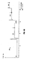
- Figure 6 is a graphical representation of the performance of a typical prior art gas chromatographic system having a split/splitless inlet such as that shown in Figure 1 , during back pressure regulation of the carrier gas flow.
- Figure 6 illustrates the carrier gas pressure level (280) while inlet carrier gas flow (290) is provided to the inlet (12) at four typical carrier gas flow rates (20ml/minute, 50 ml/minute, 100 ml/minute, and 150 ml/minute).
- the column head pressure level ramps (281, 282, 283) that accompany the flow rates at 20 ml/sec, 50 ml/sec., and 100 ml/sec., respectively, the column head pressure increases relatively slowly at these low flow rates.
- a pressure pulse is quite slow to build at such flow rates, and a run of the apparatus will take more time to complete. With fewer runs per hour of operation, a laboratory that performs repeated analyses with such apparatus will achieve less "throughput”.
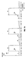
- Figure 7 is a graphical representation of the performance of an experimental prototype of the preferred embodiment, such as shown in Figures 4 and 5 , during alternating split (310) and splitless (312) modes of operation with forward pressure regulation of the carrier gas flow.
- Figure 7 illustrates the column head pressure level (300) while carrier gas flow (302) at three experimental carrier gas flow rates (320, 322, 324) is provided to the inlet (12).
- Figure 7 illustrates the column head pressure level ramps (330, 332, 334) that accompany inlet flow rates at 50 ml/sec, 100 ml/sec., and 200 ml/sec., respectively.
- Figure 7 also shows the result of a reconfiguration of the pressure and flow setpoints during transitions from split (310) to splitless (312) modes, wherein immediate pressure pulsing of the inlet may be effected.
- the pressure level changes will be recognized as being more rapid and stable across the transitions between modes.
- Column head pressure can be increased or decreased quite rapidly at the low flow rates of 50 ml/sec and 100 ml/sec.
- the desired pressure pulses (340, 342, 344) are successfully applied even at low flow rates.
- the preferred embodiment illustrated in Figures 4 - 5 is particularly distinguished in that the setpoint controller (200) cooperates with the configuration module (205) such that setpoint control of the fluid control system (110) is reconfigurable in either of three injection modes (split, splitless, or pulsed splitless), with forward pressure regulation or back pressure regulation, wherein the modes and regulation are changeable at a programmable time during a run of the gas chromatograph.
- setpoint controller 200
- configuration module (205) such that setpoint control of the fluid control system (110) is reconfigurable in either of three injection modes (split, splitless, or pulsed splitless), with forward pressure regulation or back pressure regulation, wherein the modes and regulation are changeable at a programmable time during a run of the gas chromatograph.
- the flow and pressure setpoint control output values may be optimized for each of the split, splitless, and pulsed splitless modes, resulting in improved control of the column flow and more accurate sample analysis.
- Another benefit is that the septum purge flow setpoint may be reduced and area recovery is improved in comparison to the prior art, due in part to the lower septum purge flow that is less likely to draw sample from the top of the inlet (12).
- the conventional three-way valve (20) and its associated components (not shown) are therefore unnecessary and thus are omitted. Because the stop valve (124A) is simpler and more reliable than the three way valve (20) of Figure 1 , the preferred embodiment is less costly and less subject to failure than a conventional system.
- the split vent fluid controller need not provide bubble-tight shutoff, and the controller thus may be in the form of a single valve (124B) operated according to a single setpoint control output value.
- the forward and back device drivers (210, 220) may include additional digital to analog conversion devices and signal conditioning circuitry.
Landscapes
- Physics & Mathematics (AREA)
- Health & Medical Sciences (AREA)
- Life Sciences & Earth Sciences (AREA)
- Chemical & Material Sciences (AREA)
- Analytical Chemistry (AREA)
- Biochemistry (AREA)
- General Health & Medical Sciences (AREA)
- General Physics & Mathematics (AREA)
- Immunology (AREA)
- Pathology (AREA)
- Treatment Of Liquids With Adsorbents In General (AREA)
- Sampling And Sample Adjustment (AREA)
Description
- The present invention relates to chromatographic analysis systems and, more particularly, to an apparatus and method for control of the fluid flow through a chromatographic analysis system that operates in split/splitless injection mode configurations.
- In analytical chemistry, gas chromatographic techniques have become important tools in the identification of chemical sample components. The basic mechanism underlying chromatographic analysis is the separation of a sample chemical mixture into individual components by injecting the sample into a carrier fluid (preferably a carrier gas) and transporting the mixture through a specially prepared separation column.
- Precise control of the carrier gas flow is essential for maintaining the stability of the analyte retention times and for the accuracy of the quantitation of the analyte. Electronic pressure control (EPC) systems are known to offer programmed control of fluid pressures in response to sense signals from one or more sensors. An example of a modern electronic pressure control system is disclosed, for example, in
Klein, et al., U.S. Patent No. 4,994,096 and United States Patent No.5,108,466 . Klein et al. also disclose electronic pressure control of fluids in "CGC Using a Programmable Electronic Pressure Controller," J. High Resolution Chromatography 13:361, May 1990. - A conventional gas chromatographic system may be constructed to include a particular type of injection port known as a split/splitless inlet capable of operation in either of two injection modes.
Figure 1 shows the flow paths of the carrier gas flow during a splitless injection;Figure 2 shows the flow paths of the carrier gas flow during split injection modes. As shown inFigure 1 , carrier gas is passed through a flow controller (14) to the split/splitless injection port (12) where the injected sample mixes with the carrier gas and the mixture is directed into a separation column (18). The carrier gas flow also passes to the septum purge line (12A) while any non-analyzed mixture flow is blocked in a split line (12B) by setting a three-way valve (20) to block split flow. Alternatively, as shown inFigure 2 , the three-way valve (20) can be set to pass split vent gas flow through a split vent line (12C) to a pressure controller (24) and a split vent (25), while the septum purge flow is passed to a septum purge flow controller (21) and a septum purge vent (22). - Typically, the temperature of the column (18) is controlled according to known techniques so that the sample will separate into its components. As the carrier gas (containing the sample) exits the column (18), the presence of one or more sample constituent components is detected by a detector (not shown). The pressure of the carrier gas entering the injection port (12) is controlled by the pressure controller (24) in response to an appropriate control signal.
- Certain pressure programming techniques may be used to optimize the sample separation according to the injection mode employed. In particular, the split/splitless inlet is typically operated in split or splitless injection modes with control of the column flow effected by back pressure regulation. As shown in
Figure 1 , in a splitless injection mode, the inlet (12) is first configured such that only a portion of the carrier gas that enters the inlet (12) can also enter the column (18), while the remainder "sweeps" the top of the inlet (12) and exits through the septum purge line (12A). The purge control valve (20) must be set so that the carrier gas that enters the inlet liner (12L) can only exit the split/splitless inlet into the column (18). While the purge gas continues to sweep the top of the inlet (12) and passes through the septum purge line (12A), the sample may be injected into the inlet liner (12L) and vaporized. Under ideal conditions, the vaporized sample is expected to transfer to the column during an initial "hold time" (typically 30 to 90 seconds). At the end of the splitless period, the purge valve (20) is opened (as shown inFigure 2 ), and any residual carrier gas/sample mixture remaining in the inlet liner (12L) is swept out through the split vent line (12B). - As shown in
Figure 2 , when the inlet (12) is operated in split mode, only a portion of the carrier gas that enters the inlet will also enter the column (18). Upon injection, a portion of the sample to be analyzed is carried into the column (18) while the remainder of the sample is split and directed out through the split line (12B) to the split vent line (12C) and the vent (25). The back pressure of the carrier gas exiting the injection port (12) is controlled by the pressure controller (24) in response to an appropriate control signal. - More detailed discussion of split/splitless injection techniques can be found in the prior art, such as in M.S. Klee, GC Inlets - An Introduction, Hewlett-Packard Company, February 1990; K. Grob, Classical Split and Splitless Injection in Capillary GC, 2nd Edition, Huethig, 1988; P.L. Wylie, J. Phillips, K.J. Klein, M.Q. Thompson, and B.W. Hermann, "Improving Splitless Injection with Electronic Pressure Programming,: J High Resolution Chromatography 14:649, October 1991; S. S. Stafford, K.J. Klein, P.A. Larson, F. L. Firor, and P.L. Wylie, "Applications of Electronic Pressure Control and Pressure Programming in Capillary Gas Chromatography," Hewlett-Packard Company, Application Note 228-141, Publication Number (43) 5091-2731 E, October 1991.
- In splitless injection, sample transfer from the inlet liner (12L) to the separation column (18) is not wholly effective unless the entire sample is vaporized rapidly and uniformly into a vapor cloud that is available in the inlet liner (12L) during the hold time. Splitless injection is hampered when the sample is not sufficiently vaporized, or if sample components are lost when the most volatile components of the sample vaporize rapidly, expand to fill the liner (12L), and are swept away. This phenomena (known as sample discrimination) is worsened when working quantitatively with sensitive analytes, wide boiling range mixtures, or when increasing the sample volume for greater sensitivity.
- In particular, a "high-flow" splitless injection (wherein the carrier gas entering the inlet is maintained at a high flow rate, and both the septum purge line and the split vent line are active) causes the flow over the top of the inlet to attract some of the sample into the purge line, with an undesireable loss of sample from the column, and a lowered total area count. A lower total flow rate would lessen this phenomena, but such a flow rate is impractical for effecting capillary separation because the purge flow is insufficient and the operation of the pressure controller (24) is problematic.
- A technique exists for reconcentrating the vapor cloud into a narrow band at the head of the column before chromatography begins, such that the vapor expansion volume and flow rate onto the column are controlled by altering the inlet pressure. The pressure program is set to effect a "pressure pulse" whereby the column head pressure is increased prior to injection, then rapidly reduced to a setpoint best suited for column flow. However, in conventional split/splitless inlets, the time required to increase the pressure during such transitions is more than desireable, and the column head pressure does not increase (i.e., "pulse") as rapidly and effectively as desired. Sample discrimination can result.
- Moreover, the combination of a three-way valve (20) and its associated drive circuitry contributes to the greater parts count and the increased cost of a split/splitless inlet. Three-way valves are also not as reliable as would be desired.
-
JP-A-05288373 - The journal of chromatography, Vol. 556, No. 1/2, 20 September 1999, Amsterdam NL, " deals with split-injection techniques at very low split ratios.
-
US-A-5,163,979 relates to a pressure-programmable gas chromatograph system with split and splitless operational modes. The system includes an injector for a column, with a conduit for split-injection and a purge line. A system controller is used for selecting the mode of operation. A programmable-pressure control of the system uses an oscillating back pressure regulator in the conduit. - In view of the above-referenced prior art, it is the object of the invention to provide an apparatus and a method for performing a chromatographic separation of a sample in a system that is operable in split/splitless injection modes, wherein the carrier fluid flow is more accurately and reliably controlled, to afford an increased total area count, with use of a simpler and less-expensive arrangement of components.
- This object is achieved by an apparatus in accordance with
claim 1. - The preferred embodiments of the contemplated gas chromatographic analysis system accomplish more accurate and repeatable control of the column fluid flow during transitions between split and splitless modes, and during operation in the splitless mode.
-
-
Figure 1 is a simplified representation of the fluid flow in a conventional split/splitless inlet, during operation in a splitless injection mode, showing the split split "off" condition. -
Figure 2 is a simplified representation of the fluid flow in the split/splitless inlet ofFigure 1 , during operation in a split injection mode, showing the split "on" condition. -
Figure 3A is a simplified schematic representation of a preferred embodiment of a gas chromatographic analysis system constructed according to the present invention. -
Figure 3B is a graphical representation of some of the control tables used by the gas chromatographic analysis system ofFigure 3A . -
Figure 4A is a simplified schematic representation of the preferred embodiment ofFigure 3 , during operation in a first mode preferred for split injection. -
Figure 4B is a simplified schematic representation of the preferred embodiment ofFigure 3A , during operation in a second mode preferred for splitless injection. -
Figure 5 is a simplified schematic representation of a particularly preferred embodiment of the fluid controller ofFigure 3A . -
Figures 6A and6B are graphical representations of the column head pressure and inlet carrier gas flow, respectively, in the system ofFigure 1 . -
Figures 7A and7B are graphical representations of the column head pressure and inlet carrier gas flow, respectively, in the particularly preferred embodiment ofFigure 5 , during alternating split and splitless injection modes, illustrating improved forward pressure control of the column head pressure. - The apparatus and methods of the present invention may be employed to improve the control of the flow of a variety of compressible fluids in an analytical chromatographic system. Such fluids are intended to include gases, liquids, multiple component gases and liquids, and mixtures thereof capable of regulated flow. Gases are the preferred fluids according to the practice of the present invention, and therefore the following description of the invention will be directed to a gas chromatographic analytical system. Further, the description herein is directed to certain pneumatic characteristics of the fluid flow, such as pressure. The carrier gas may comprise one or more component gases (such as hydrogen, nitrogen, argon, methane, or helium) depending upon the particular chromatographic separation to be performed. However, it should be understood that the teachings herein are applicable to other fluids.
- As shown in
Figures 3 - 5 , a gas chromatographic analysis system (100) may be constructed according to the present invention to include certain components already described with reference toFigures 1 - 2 . Components of like nomenclature and reference numerals are intended to be equivalent. - The preferred embodiment (100) of
Figure 3A is constructed as a keyboard-operated, table-driven gas chromatograph wherein the system configuration and operation, and particularly the operation of the gas streams for the unit's injection and detection systems, can be controlled by use of an input/output device (102) or via a communication line to a remote controller (107) such as a computer workstation, central control station, or another gas chromatograph. The operator may perform data entry and control table editing by way of a keyboard (106). A status board (108) displays information about the current status of certain systems while the chromatograph is in operation. - Actual values of certain operating parameters, and system control values (also stated herein as setpoints), are organized into one or more control tables that are created in response to data from the remote controller (107) or (preferably) in response to data input by the operator on the input/output device (102) and to programming and firmware operative in a system controller (109). The tables are viewable and editable on a display (104).
Figure 3B illustrates examples of a few tables (inlet, column, and mode control tables (150, 160, 170)) as they would be rendered on the display (104). Examples of certain parameters of interest are: column dimensions (162), actual column pressure (163), column pressure setpoint (164), column flow rate (165), and calculated average linear velocity (166), and control mode (168). - The system controller (109) preferably includes data acquisition, memory, computation, and other process control circuitry suited for initiating and controlling the various functions relative to operation of the gas chromatograph (100), and software and/or firmware pertinent to carrying out the functions and operations indicated in the control tables, and in particular the generation, storage, and editing of the tables indicated on the display (104). The gas chromatograph (100) is preferably operable in split and splitless injection modes, with the latter including an optional pulsed splitless mode. A mode may be selected by use of the mode table (150) displayed on the input/output device (102). A pulsed splitless mode, for example, may include a pressure pulse feature, wherein the inlet pressure is increased at the beginning of an analysis and then is reduced to a normal level after selectable delay time.
- In the preferred embodiment, regulated carrier gas flow is provided via a inlet flow fluid controller, preferably in the form of a proportional control valve (114), to the split/splitless injection port (12). During a split injection mode, a sample is introduced into the heated inlet (12) where it vaporizes. A small amount of the sample/carrier gas mixture enters the column (18) while the majority of the sample/carrier gas mixture is vented out of the split vent (25). The split flow/column flow mixture ratio may be set by the operator according to the use of the input/output device (102) or remote controller (107) described above. In a splitless mode injection, a split line control valve (124) in the form of a bubble-tight shutoff valve (124A) and a proportional valve (124B) is closed during the injection and remains closed while the sample is vaporized and transferred to the column (18). At an operator-specified time after the injection, and the sample/carrier gas mixture has been received into the separation column (18), the split vent fluid controller is opened and any vapors remaining in the inlet are purged. Purge time and flow rate may be specified by editing the inlet control table (150).
- Depending upon the injection mode and the control table setpoints in effect, flow may pass through a combination of a septum purge line (112A) or a split line (112B), or both. However, the conventional three-way purge valve (20) (in
Figures 1-2 ) is omitted. Septum purge flow is directed to the septum purge controller (21), flow restrictor (22), and septum purge vent (23); split vent flow passes directly to the shutoff valve (124A) and proportional control valve (124B), and then to a split vent (25). InFigure 3A , the shutoff valve (124A) is illustrated in the "open" (full flow) position; a "closed" (zero flow) position is optionally selectable, as will be described below. - With reference in particular to
Figures 4-5 , the preferred embodiment may be seen to include a reconfigurable fluid control system (110) having a setpoint controller (200) that receives a first sense signal from a first sensor (115) by way of sense line (116A). The first sensor (115) is preferably an inlet flow sensor that provides a sense signal representative of the inlet gas flow, and accordingly the setpoint controller (200) is implemented to provide a first setpoint control output value on output line (203). The setpoint controller (200) receives a second sense signal from a second sensor (126) by way of sense line (127). The second sensor (126) is preferably a gage pressure sensor that provides a sense signal representative of the pressure at a point in the septum purge line (112A), which is indirectly representative of the column head pressure at the head of the column (18). Accordingly the setpoint controller (200) is preferably implemented to provide a second setpoint control output value on output line (204). - As will now be described, the aforementioned first and second setpoint control output values are determined by the setpoint controller (200) according to pressure and flow control programming in response to one or more parameters and modes selected from the control tables. In the preferred embodiment, the selection criteria includes the injection mode (split, splitless, or pulsed splitless), and related conditions, such as the onset of an inlet purge during a splitless injection mode. However, it is contemplated that other criteria may be used. Further, the application of the setpoint control output values by the fluid control system (110) to the inlet control valve (114) and split line control valve (124) is selectably reconfigurable at any time in accordance with the control tables that are currently operative. Additionally, the fluid control system (110) interacts with the system controller (109) to send and receive other data and control signals. For example, actual values such as the actual inlet pressure, and setpoint values, such as the column head pressure setpoint, may be provided to the system controller (109) for display on the input output device (102).
- Each of the first and second setpoint control output values on respective lines (203, 204) from the setpoint controller (200) are actively directed by a configuration module (205) to a forward device driver (210) or back device driver (220). The forward device driver (210) converts the setpoint control output value that it has received to a control signal for use by the proportional control valve (114). The back device driver (220) converts the received setpoint control output value to a control signal for use by the proportional valve (124B). The fluid flow entering the injection port (12) on the inlet line is thereby controlled by the control valve (114) in response to a signal applied on the first control line (116B). The pressure of the carrier gas exiting the injection port (12) on the split line (112B) is thereby controlled by the split vent control valve (124) in response to a signal applied on a second control line (128). In the illustrated embodiment, wherein the shutoff valve (1 24A) is preferred to ensure bubble-tight closure of the proportional control valve (124B), a third setpoint control output value is selectably provided to a shutoff device driver (222) on line (202).
- In
Figure 4A , the configuration module (205) is illustrated in a first configuration preferred for a split injection mode, wherein the first setpoint control output value is directed to the forward device driver (210) which drives the inlet control valve (114) to control the carrier gas inlet flow at the inlet (12), and the second setpoint control output value may be directed to the back device driver (220) to drive the split vent control valve (124). As the column head pressure at the head of the separation column (18) is directly related to the split vent pressure controlled by the split vent control valve (124), the column head pressure is thereby controlled. The third setpoint control output value is provided to the shutoff valve (124A) to fully open the shutoff valve. - In
Figure 4B , the configuration module (205) is illustrated in a second configuration preferred for splitless and pulsed splitless injection, wherein the first setpoint control output value is directed to the back device driver (220) to drive the split vent proportional control valve (124B), and the second setpoint control output value is directed to the forward device driver (210) to control the septum purge line pressure, which is directly related to the column head pressure during splitless operation, and hence the column head pressure is thereby controlled. The third setpoint control output value is provided to the shutoff valve (124A) to ensure zero split flow. - A particular feature of the present invention is that the aforementioned modes, conditions, and configurations may be implemented and changed 'on-the-fly', that is, at a programmable time during the run of a chromatographic separation. It will be appreciated by those skilled in the art that
Figures 4 and5 show simplified schematic illustrations of closed loop control circuits; thus, the programmable fluid control system (110) is contemplated as being implemented by use of one or a combination of the following: analog hardware, digital hardware, digital memory, programmable software, and firmware. - Accordingly,
Figure 5 illustrates a particularly preferred embodiment wherein the setpoint controller (110) and configuration module (205) are implemented in the form of an embedded digital microprocessor operating memory arrays under the control of control firmware. Thus, analog to digital (A/D) converters (231, 232) in combination with an actual value generator (234) provide actual values av1, av2, ...avn to an actual value array (236) maintained by a processor (238). Control table values and other data are received from the system controller (109) (ofFigure 3A ) by a mode and setpoint generator (240), which then provides control setpoints cs1, cs2, ...csn to a control setpoint array (242). A comparator algorithm (244) compares each actual value to its respective control setpoint and computes respective error values ev1, ev2, ...evn for storage in an error value array (246). A proportional integral derivative (PID) algorithm (248) then computes respective controller output values ov1, ov2, ...ovn for storage in an output value array (250). A controller output pointer array (252A, or in the alternative, 252B) holds output pointers op1, op2, ...opn. The output values ov1, ov2, ...ovn may thereby be directed to an output address array (254A, or in the alternative, 254B) according to the output pointers op1, op2, ...opn . As illustrated in the change from array (252A) to the array (252B), by changing the values of the output pointers, the output values may be reconfigured from a first arrangement ov1, ov2, ...ovn in the output address array (254A), to a second arrangement ov2, ov1, ...ovn in the reconfigured output address array (254B) illustrated in broken lines. In summary, the renumbering of the output pointers serves to redirect the location of the output values in the output address array. -
Figure 6 is a graphical representation of the performance of a typical prior art gas chromatographic system having a split/splitless inlet such as that shown inFigure 1 , during back pressure regulation of the carrier gas flow.Figure 6 illustrates the carrier gas pressure level (280) while inlet carrier gas flow (290) is provided to the inlet (12) at four typical carrier gas flow rates (20ml/minute, 50 ml/minute, 100 ml/minute, and 150 ml/minute). As indicated by the column head pressure level ramps (281, 282, 283) that accompany the flow rates at 20 ml/sec, 50 ml/sec., and 100 ml/sec., respectively, the column head pressure increases relatively slowly at these low flow rates. As a result, a pressure pulse is quite slow to build at such flow rates, and a run of the apparatus will take more time to complete. With fewer runs per hour of operation, a laboratory that performs repeated analyses with such apparatus will achieve less "throughput". - In contrast,
Figure 7 is a graphical representation of the performance of an experimental prototype of the preferred embodiment, such as shown inFigures 4 and5 , during alternating split (310) and splitless (312) modes of operation with forward pressure regulation of the carrier gas flow.Figure 7 illustrates the column head pressure level (300) while carrier gas flow (302) at three experimental carrier gas flow rates (320, 322, 324) is provided to the inlet (12).Figure 7 illustrates the column head pressure level ramps (330, 332, 334) that accompany inlet flow rates at 50 ml/sec, 100 ml/sec., and 200 ml/sec., respectively.Figure 7 also shows the result of a reconfiguration of the pressure and flow setpoints during transitions from split (310) to splitless (312) modes, wherein immediate pressure pulsing of the inlet may be effected. The pressure level changes will be recognized as being more rapid and stable across the transitions between modes. Column head pressure can be increased or decreased quite rapidly at the low flow rates of 50 ml/sec and 100 ml/sec. As a result, the desired pressure pulses (340, 342, 344) are successfully applied even at low flow rates. - The example listed below represents the performance of an experimental prototype of the preferred embodiment, such as shown in
Figures 4 and5 , during alternating split (310) and splitless (312) modes of operation, in comparison to a conventional chromatographic system constructed according to the system (10) ofFigure 1 . As is shown below, the experimental protype offers a performance improvement over prior art systems. -
System Configuration Description 1. Auto/splt/Modified-EPC Preferred embodiment with autosampler; operated in split mode; back pressure regulation 2. Auto/spls/Modified-EPC Preferred embodiment with autosampler;operated in splitless mode; forward pressure regulation 3. Auto/PCOC/C-EPC Conventional system with autosampler operated in cool-on column mode 4. Manual/PCOC/C-EPC Conventional system, manual injection, cool-on column inlet 5. Auto/splt/Manual Conventional system with autosampler, inlet operated in split mode, manual pressure control System Configuration Retention Time Standard Deviation Rance (min) 1. Auto/splt/Modified-EPC 0.001- 0.005 2. Auto/spls/Modified-EPC 0.001- 0.009 3. Auto/PCOC/C-EPC 0.002 - 0.024 5. Auto/spit/Manual 0.005 - 0.019 System Configuration Area Precision, % Range in Standard Deviation Total Area 1. Auto/spls/Modified-EPC 0.25 - 1.86 0.59 2. Auto/spIt/Modified-EPC 1.10-3.19 1.59 3. Auto/PCOC/C-EPC 0.18 - 1.68 0.35 4. Man/PCOC/C-EPC 1.97 - 7.82 3.42 5. Auto/splt/man 1.15 - 4.47 2.26 - With respect to the prior art systems described with respect to
Figures 1 - 2 , the preferred embodiment illustrated inFigures 4 - 5 is particularly distinguished in that the setpoint controller (200) cooperates with the configuration module (205) such that setpoint control of the fluid control system (110) is reconfigurable in either of three injection modes (split, splitless, or pulsed splitless), with forward pressure regulation or back pressure regulation, wherein the modes and regulation are changeable at a programmable time during a run of the gas chromatograph. - Further, the requisite transitions in column head pressure between these injection modes are effected more rapidly. Pressure pulse programming may thus be implemented more quickly in the preferred embodiment than in the prior art. The flow and pressure setpoint control output values may be optimized for each of the split, splitless, and pulsed splitless modes, resulting in improved control of the column flow and more accurate sample analysis. Another benefit is that the septum purge flow setpoint may be reduced and area recovery is improved in comparison to the prior art, due in part to the lower septum purge flow that is less likely to draw sample from the top of the inlet (12).
- The conventional three-way valve (20) and its associated components (not shown) are therefore unnecessary and thus are omitted. Because the stop valve (124A) is simpler and more reliable than the three way valve (20) of
Figure 1 , the preferred embodiment is less costly and less subject to failure than a conventional system. - Although the invention has been described with reference to the above-described preferred embodiments, variations and modifications are contemplated as being within the scope of the claims. For example, although only two of the output values are illustrated as being redirected in the output address array (254A to 254B), it is contemplated that any number of output values may be redirected. Moreover, certain ones of the output values may be provided from the output address array (254) to additional device drivers (not shown) on additional lines (indicated by the additional device driver line (260)). In certain applications of the present invention, the split vent fluid controller need not provide bubble-tight shutoff, and the controller thus may be in the form of a single valve (124B) operated according to a single setpoint control output value. Further, the forward and back device drivers (210, 220) may include additional digital to analog conversion devices and signal conditioning circuitry.
Claims (7)
- Apparatus for performing a chromatographic separation of a sample, comprising:an injection port (12) having an inlet therein for combining the sample and an inlet fluid and for providing a column fluid flow to a separation column (18), wherein the injection port (12) includes an inlet line, a split line (112B), and a septum purge line (112A) for passing respectively an inlet fluid flow, a split fluid flow, and a septum purge flow;sense means for providing sense information representative of the fluid flow in the inlet line and the fluid pressure in the septum purge line (112A), which is directly representative of the column head pressure at the head of the column (18);a first control valve (114) operatively connected to the inlet line;;a second control valve (124B) operatively connected to the split line (112B);
the apparatus characterized in that it further comprises:a system controller (109) for providing control table information representative of a selected one of split and splitless injection modes and a selected one of forward and back pressure regulation modes;a reconfigurable fluid control system (110) having:a) a setpoint controller (200) for determining first and second setpoint control output values, in accordance with the sense information and the control table information, andb) a configuration module (205) for controlling the first and second control valves (114, 124B) according to the first and second setpoint control output values, respectively, when the injection port (12) is operated in a split injection mode, and for controlling the second and first control valves (124B, 114) according to the first and second setpoint control output values, respectively, when the injection port is (12) operated in a splitless injection mode - The apparatus of claim 1, wherein the first and second setpoint control values effect back pressure regulation of the split mode injection.
- The apparatus of claim 1, wherein the first and second setpoint control values effect forward pressure regulation of the splitless mode injection.
- The apparatus of claim 1, wherein the reconfigurable fluid control system (110) includes program control to provide a pulsed splitless mode injection.
- The apparatus of claim 1, further comprising a shutoff valve (124A), operatively connected to the split line (112B), wherein the fluid control system (110) further comprises:a forward device driver (210), responsive to the first setpoint control output value (124B),a back device driver (220), responsive to the second setpoint control output value,a shutoff device driver (222), responsive to a third setpoint control output value,wherein the forward device driver (210) is operatively connected to the first control valve (114) for controlling fluid flow in the inlet line, and the second control valve (124B) and the shutoff valve (124A) are operatively connected to the back device driver (220) and shutoff device driver(222), respectively, for effecting control of the fluid pressure in the split line (112B).
- The apparatus of claim 1, further comprising an input/output device (102) for receiving input data and for displaying control table information pertinent to the operation of the system controller (109).
- The apparatus of claim 1, wherein the reconfigurable fluid control system (110) further comprises:an actual value array (236) for storage and retrieval of plural actual values (av1, av2, ...avn) representative of selected system operating parameters;a mode and setpoint generator for providing plural control setpoints (cs1. cs2, ...csn) representative of selected control table values;a control setpoint array (242) for storage and retrieval of the control setpoints;a comparator algorithm for comparing each actual value to its respective control setpoint and computing plural respective error values (ev1, ev2, ...evn);an error value array (246) for storage and retrieval of the computed error values;a proportional integral derivative algorithm for computing a plurality of respective controller output values (ov1, ov2, ...ovn);an output value array (250) for storage and retrieval of the controller output values;a controller output pointer array (252A, 252B) for storage and retrieval of a plurality of output pointers (op1, op2, ...opn); andan output address array (254A, 254B) for receiving the output values (ov1, ov2, ...ovn) from the output value array according to the output pointers (op1, op2, ...opn);wherein the values of the output pointers are programmable to reconfigure the output values in the output address array from a first order of values to a second order of values.
Applications Claiming Priority (2)
| Application Number | Priority Date | Filing Date | Title |
|---|---|---|---|
| US08/251,830 US5431712A (en) | 1994-05-31 | 1994-05-31 | Reconfigurable pneumatic control for split/splitless injection |
| US251830 | 1994-05-31 |
Publications (2)
| Publication Number | Publication Date |
|---|---|
| EP0685738A1 EP0685738A1 (en) | 1995-12-06 |
| EP0685738B1 true EP0685738B1 (en) | 2010-04-21 |
Family
ID=22953592
Family Applications (1)
| Application Number | Title | Priority Date | Filing Date |
|---|---|---|---|
| EP95101256A Expired - Lifetime EP0685738B1 (en) | 1994-05-31 | 1995-01-30 | Reconfigurable pneumatic control for split/splitless injection |
Country Status (4)
| Country | Link |
|---|---|
| US (1) | US5431712A (en) |
| EP (1) | EP0685738B1 (en) |
| JP (1) | JP3472386B2 (en) |
| DE (1) | DE69536067D1 (en) |
Families Citing this family (24)
| Publication number | Priority date | Publication date | Assignee | Title |
|---|---|---|---|---|
| US5567227A (en) * | 1995-01-23 | 1996-10-22 | Hewlett-Packard Company | Method for improving the range of stable control of the pneumatic system of a gas chromatograph |
| US5545252A (en) * | 1995-03-01 | 1996-08-13 | The Perkin-Elmer Corporation | Flow regulation in gas chromatograph |
| US5642271A (en) * | 1995-08-31 | 1997-06-24 | Hewlett-Packard Company | Pneumatic control system |
| US5711786A (en) * | 1995-10-23 | 1998-01-27 | The Perkin-Elmer Corporation | Gas chromatographic system with controlled sample transfer |
| IT1277749B1 (en) * | 1995-12-29 | 1997-11-12 | Fisons Instr Spa | DEVICE AND METHOD FOR PERFORMING THE SEPARATION OF A SAMPLE INTO SINGLE COMPONENTS IN A CAPILLARY DUCT OF AN EQUIPMENT FOR |
| JP3424432B2 (en) * | 1996-04-03 | 2003-07-07 | 株式会社島津製作所 | Gas chromatograph |
| IT1282965B1 (en) * | 1996-05-08 | 1998-04-03 | Fisons Instr Spa | PROCEDURE AND DEVICE FOR INJECTION OF LIQUID SAMPLES INTO A GC. |
| JP3543532B2 (en) * | 1997-01-30 | 2004-07-14 | 株式会社島津製作所 | Gas chromatograph |
| US6063166A (en) * | 1998-07-30 | 2000-05-16 | Hewlett-Packard Company | Chromatograph having a gas storage system |
| JP2003207492A (en) * | 2002-01-10 | 2003-07-25 | Shimadzu Corp | Gas chromatograph |
| RU2306556C2 (en) * | 2002-02-22 | 2007-09-20 | Дани Инструментс С.П.А. | Flow control device for the analytical circuit and its usage in chromatography |
| EP1478922A1 (en) | 2002-02-22 | 2004-11-24 | Dani Instruments S.p.A. | Flow regulator device for an analytical circuit and its use in chromatography |
| US6648609B2 (en) * | 2002-04-05 | 2003-11-18 | Berger Instruments, Inc. | Pump as a pressure source for supercritical fluid chromatography involving pressure regulators and a precision orifice |
| US7258132B2 (en) * | 2004-06-18 | 2007-08-21 | Agilent Technologies, Inc. | Electronically controlled back pressure regulator |
| US20060219637A1 (en) * | 2005-03-29 | 2006-10-05 | Killeen Kevin P | Devices, systems and methods for liquid chromatography |
| US20070016333A1 (en) * | 2005-07-12 | 2007-01-18 | Edwards Grant B | Method and apparatus for controlling the valve position of a variable orifice flow meter |
| DE102005050114A1 (en) * | 2005-10-18 | 2007-04-19 | Studiengesellschaft Kohle Mbh | Analysis of mixtures |
| US8141411B2 (en) * | 2008-09-30 | 2012-03-27 | Thermo Finnigan Llc | Method for determining a low cylinder pressure condition for a gas chromatograph |
| US8343258B2 (en) | 2010-03-30 | 2013-01-01 | Agilent Technologies, Inc. | Apparatus and method for controlling constant mass flow to gas chromatography column |
| US8887586B2 (en) * | 2010-10-29 | 2014-11-18 | Agilent Technologies, Inc. | Head space sampling device and method for detecting leaks in same |
| US9429499B2 (en) | 2010-10-29 | 2016-08-30 | Agilent Technologies, Inc. | Methods, devices, and systems for controlling the rate of gas depressurization within a vial containing a gas sample |
| JP2014134392A (en) * | 2013-01-08 | 2014-07-24 | Shimadzu Corp | Gas chromatograph device |
| CN105467049B (en) | 2014-05-26 | 2019-06-28 | 安捷伦科技有限公司 | Gas-chromatography unit, expansible gas chromatography system and correlation technique with the identical unit |
| WO2022026131A1 (en) * | 2020-07-27 | 2022-02-03 | Agilent Technologies, Inc. | Methods and systems for carrier gas identification in gas chromatography |
Family Cites Families (7)
| Publication number | Priority date | Publication date | Assignee | Title |
|---|---|---|---|---|
| GB1214627A (en) * | 1967-02-02 | 1970-12-02 | Perkin Elmer Ltd | Improvements in or relating to pressure programmers |
| US4994096A (en) * | 1989-05-09 | 1991-02-19 | Hewlett-Packard Co. | Gas chromatograph having integrated pressure programmer |
| US4948389A (en) * | 1989-05-22 | 1990-08-14 | Hewlett-Packard Company | Gas chromatograph having cyro blast coolings |
| US5141534A (en) * | 1990-09-28 | 1992-08-25 | The Regents Of The University Of Michigan | Sample collection and inlet systems for gas chromatography apparatus |
| US5108466A (en) * | 1990-12-21 | 1992-04-28 | Hewlett-Packard Company | Apparatus and methods for controlling fluids provided to a chromatographic detector |
| US5163979A (en) * | 1991-06-27 | 1992-11-17 | The Dow Chemical Company | Pressure programmable gas chromatograph regulator |
| JPH0769315B2 (en) * | 1992-04-06 | 1995-07-26 | 株式会社島津製作所 | Gas chromatograph |
-
1994
- 1994-05-31 US US08/251,830 patent/US5431712A/en not_active Expired - Lifetime
-
1995
- 1995-01-30 DE DE69536067T patent/DE69536067D1/en not_active Expired - Lifetime
- 1995-01-30 EP EP95101256A patent/EP0685738B1/en not_active Expired - Lifetime
- 1995-05-31 JP JP15714995A patent/JP3472386B2/en not_active Expired - Fee Related
Also Published As
| Publication number | Publication date |
|---|---|
| DE69536067D1 (en) | 2010-06-02 |
| US5431712A (en) | 1995-07-11 |
| EP0685738A1 (en) | 1995-12-06 |
| JP3472386B2 (en) | 2003-12-02 |
| JPH07333207A (en) | 1995-12-22 |
Similar Documents
| Publication | Publication Date | Title |
|---|---|---|
| US5431712A (en) | Reconfigurable pneumatic control for split/splitless injection | |
| EP0770869B1 (en) | Gas chromatographic system with controlled sample transfer | |
| EP0396884B1 (en) | Gas chromatograph having integrated pressure programmer | |
| JP3526102B2 (en) | Chromatographic analysis of fluids | |
| US4948389A (en) | Gas chromatograph having cyro blast coolings | |
| US20070261474A1 (en) | System For Regulating Fluid Flowing Through Chromatographic Column | |
| US7258132B2 (en) | Electronically controlled back pressure regulator | |
| EP1613943B1 (en) | System and method for extracting headspace vapor | |
| US5339673A (en) | Gas chromatograph and method of using same | |
| EP0878712A2 (en) | Standardization of chromatographic systems | |
| JPH07198693A (en) | Method and device for continuous excreta monitoring system using gas chromatography | |
| US20080264491A1 (en) | Fluid multiplexer for capillary column gas chromatography | |
| US20090277245A1 (en) | Methods And Systems For Cooling A Chromatographic Column | |
| US8247239B2 (en) | System for introducing standard gas into sample container | |
| EP0847522A1 (en) | System and method for monitoring volatile species | |
| EP0654667A1 (en) | Gas chromatography systems | |
| JP7447774B2 (en) | Gas analyzer and gas analyzer status detection method | |
| US5554540A (en) | Method and apparatus for preserving the sensitivity of a thermionic ionization detector | |
| GB2310611A (en) | Providing samples for chromatographics | |
| JPH08240563A (en) | Analyzer and analyzing method | |
| JP2001174445A (en) | Gas chromatograph apparatus and its adjustment method | |
| JP2508040B2 (en) | Gas chromatograph | |
| JP3463413B2 (en) | Gas chromatograph | |
| Winter et al. | Operational Qualification in Practice for Gas Chromatography Instruments |
Legal Events
| Date | Code | Title | Description |
|---|---|---|---|
| PUAI | Public reference made under article 153(3) epc to a published international application that has entered the european phase |
Free format text: ORIGINAL CODE: 0009012 |
|
| 17P | Request for examination filed |
Effective date: 19950912 |
|
| AK | Designated contracting states |
Kind code of ref document: A1 Designated state(s): DE GB IT |
|
| RAP1 | Party data changed (applicant data changed or rights of an application transferred) |
Owner name: HEWLETT-PACKARD COMPANY, A DELAWARE CORPORATION |
|
| RAP1 | Party data changed (applicant data changed or rights of an application transferred) |
Owner name: AGILENT TECHNOLOGIES, INC. |
|
| RAP1 | Party data changed (applicant data changed or rights of an application transferred) |
Owner name: AGILENT TECHNOLOGIES INC. |
|
| RAP1 | Party data changed (applicant data changed or rights of an application transferred) |
Owner name: AGILENT TECHNOLOGIES INC. A DELAWARE CORPORATION |
|
| RAP1 | Party data changed (applicant data changed or rights of an application transferred) |
Owner name: AGILENT TECHNOLOGIES, INC. (A DELAWARE CORPORATION |
|
| 17Q | First examination report despatched |
Effective date: 20030331 |
|
| 17Q | First examination report despatched |
Effective date: 20030404 |
|
| RAP1 | Party data changed (applicant data changed or rights of an application transferred) |
Owner name: AGILENT TECHNOLOGIES, INC. |
|
| GRAP | Despatch of communication of intention to grant a patent |
Free format text: ORIGINAL CODE: EPIDOSNIGR1 |
|
| RIC1 | Information provided on ipc code assigned before grant |
Ipc: G01N 30/32 20060101ALI20090922BHEP Ipc: G01N 30/24 20060101AFI20090922BHEP |
|
| GRAS | Grant fee paid |
Free format text: ORIGINAL CODE: EPIDOSNIGR3 |
|
| GRAA | (expected) grant |
Free format text: ORIGINAL CODE: 0009210 |
|
| AK | Designated contracting states |
Kind code of ref document: B1 Designated state(s): DE GB IT |
|
| REG | Reference to a national code |
Ref country code: GB Ref legal event code: FG4D |
|
| REF | Corresponds to: |
Ref document number: 69536067 Country of ref document: DE Date of ref document: 20100602 Kind code of ref document: P |
|
| PLBE | No opposition filed within time limit |
Free format text: ORIGINAL CODE: 0009261 |
|
| STAA | Information on the status of an ep patent application or granted ep patent |
Free format text: STATUS: NO OPPOSITION FILED WITHIN TIME LIMIT |
|
| 26N | No opposition filed |
Effective date: 20110124 |
|
| PG25 | Lapsed in a contracting state [announced via postgrant information from national office to epo] |
Ref country code: IT Free format text: LAPSE BECAUSE OF FAILURE TO SUBMIT A TRANSLATION OF THE DESCRIPTION OR TO PAY THE FEE WITHIN THE PRESCRIBED TIME-LIMIT Effective date: 20100421 |
|
| PGFP | Annual fee paid to national office [announced via postgrant information from national office to epo] |
Ref country code: GB Payment date: 20130130 Year of fee payment: 19 Ref country code: DE Payment date: 20130123 Year of fee payment: 19 |
|
| REG | Reference to a national code |
Ref country code: DE Ref legal event code: R119 Ref document number: 69536067 Country of ref document: DE |
|
| GBPC | Gb: european patent ceased through non-payment of renewal fee |
Effective date: 20140130 |
|
| REG | Reference to a national code |
Ref country code: DE Ref legal event code: R119 Ref document number: 69536067 Country of ref document: DE Effective date: 20140801 |
|
| PG25 | Lapsed in a contracting state [announced via postgrant information from national office to epo] |
Ref country code: DE Free format text: LAPSE BECAUSE OF NON-PAYMENT OF DUE FEES Effective date: 20140801 |
|
| PG25 | Lapsed in a contracting state [announced via postgrant information from national office to epo] |
Ref country code: GB Free format text: LAPSE BECAUSE OF NON-PAYMENT OF DUE FEES Effective date: 20140130 |