EP0685218A1 - First-aid portable apparatus for washing an eye and/or the skin - Google Patents
First-aid portable apparatus for washing an eye and/or the skin Download PDFInfo
- Publication number
- EP0685218A1 EP0685218A1 EP94401205A EP94401205A EP0685218A1 EP 0685218 A1 EP0685218 A1 EP 0685218A1 EP 94401205 A EP94401205 A EP 94401205A EP 94401205 A EP94401205 A EP 94401205A EP 0685218 A1 EP0685218 A1 EP 0685218A1
- Authority
- EP
- European Patent Office
- Prior art keywords
- liquid
- movable head
- dispensing device
- outlet
- eye
- Prior art date
- Legal status (The legal status is an assumption and is not a legal conclusion. Google has not performed a legal analysis and makes no representation as to the accuracy of the status listed.)
- Granted
Links
Images

Classifications
-
- B—PERFORMING OPERATIONS; TRANSPORTING
- B65—CONVEYING; PACKING; STORING; HANDLING THIN OR FILAMENTARY MATERIAL
- B65D—CONTAINERS FOR STORAGE OR TRANSPORT OF ARTICLES OR MATERIALS, e.g. BAGS, BARRELS, BOTTLES, BOXES, CANS, CARTONS, CRATES, DRUMS, JARS, TANKS, HOPPERS, FORWARDING CONTAINERS; ACCESSORIES, CLOSURES, OR FITTINGS THEREFOR; PACKAGING ELEMENTS; PACKAGES
- B65D83/00—Containers or packages with special means for dispensing contents
- B65D83/14—Containers or packages with special means for dispensing contents for delivery of liquid or semi-liquid contents by internal gaseous pressure, i.e. aerosol containers comprising propellant for a product delivered by a propellant
- B65D83/16—Containers or packages with special means for dispensing contents for delivery of liquid or semi-liquid contents by internal gaseous pressure, i.e. aerosol containers comprising propellant for a product delivered by a propellant characterised by the actuating means
- B65D83/20—Containers or packages with special means for dispensing contents for delivery of liquid or semi-liquid contents by internal gaseous pressure, i.e. aerosol containers comprising propellant for a product delivered by a propellant characterised by the actuating means operated by manual action, e.g. button-type actuator or actuator caps
- B65D83/205—Actuator caps, or peripheral actuator skirts, attachable to the aerosol container
-
- A—HUMAN NECESSITIES
- A61—MEDICAL OR VETERINARY SCIENCE; HYGIENE
- A61H—PHYSICAL THERAPY APPARATUS, e.g. DEVICES FOR LOCATING OR STIMULATING REFLEX POINTS IN THE BODY; ARTIFICIAL RESPIRATION; MASSAGE; BATHING DEVICES FOR SPECIAL THERAPEUTIC OR HYGIENIC PURPOSES OR SPECIFIC PARTS OF THE BODY
- A61H35/00—Baths for specific parts of the body
- A61H35/02—Baths for specific parts of the body for the eyes
-
- B—PERFORMING OPERATIONS; TRANSPORTING
- B05—SPRAYING OR ATOMISING IN GENERAL; APPLYING FLUENT MATERIALS TO SURFACES, IN GENERAL
- B05B—SPRAYING APPARATUS; ATOMISING APPARATUS; NOZZLES
- B05B1/00—Nozzles, spray heads or other outlets, with or without auxiliary devices such as valves, heating means
- B05B1/14—Nozzles, spray heads or other outlets, with or without auxiliary devices such as valves, heating means with multiple outlet openings; with strainers in or outside the outlet opening
- B05B1/16—Nozzles, spray heads or other outlets, with or without auxiliary devices such as valves, heating means with multiple outlet openings; with strainers in or outside the outlet opening having selectively- effective outlets
- B05B1/1627—Nozzles, spray heads or other outlets, with or without auxiliary devices such as valves, heating means with multiple outlet openings; with strainers in or outside the outlet opening having selectively- effective outlets with a selecting mechanism comprising a gate valve, a sliding valve or a cock
- B05B1/1636—Nozzles, spray heads or other outlets, with or without auxiliary devices such as valves, heating means with multiple outlet openings; with strainers in or outside the outlet opening having selectively- effective outlets with a selecting mechanism comprising a gate valve, a sliding valve or a cock by relative rotative movement of the valve elements
Definitions
- the present invention relates to improvements made to portable first aid devices for washing an eye and / or the skin, in particular following a projection of a chemical agent (acid, base, solvent, toxic) or '' a thermal burn.
- a chemical agent ascid, base, solvent, toxic
- the object of the invention is essentially to propose an improved device which eliminates the aforementioned drawbacks of the devices currently known and which gives better satisfaction to the various requirements of practice.
- a portable first aid device as mentioned in the preamble, being arranged in accordance with the invention, is essentially characterized in that the dispensing device comprises a member for adjusting the jet of liquid leaving said valve, which member is able to be adjusted from a first extreme position for which the dispensing device projects a jet of finely atomized liquid to a second extreme position for which the dispensing device dispenses a substantially continuous flow of washing liquid; in addition, the dispensing device comprises a functionally active eyelet at least when the adjustment member is in the aforesaid second extreme position for collecting the liquid dispensed in continuous flow in order to allow a bath for the injured eye.
- the apparatus of the invention makes it possible to adapt the washing process according to the location (eye and / or skin) and the extent of the damage and in particular it offers the choice between spraying the washing which, flowing over the face, carries with it the foreign product or else a total washing by bathing the eye in an eye-cup which offers the advantage of complete and total contact of the washing liquid with the whole from the surface of the eye and the eyelid.
- the adjusting member In order to simplify the structure of the device as much as possible and therefore to allow relatively inexpensive manufacturing allowing wide distribution of this type of device, provision is preferably made for the adjusting member to be arranged to selectively occupy only two functional positions corresponding to the two aforementioned extreme positions.
- the adjustment member it is also possible for the adjustment member to be arranged so as to be able to occupy a third intermediate, non-functional position, in which the outlet valve of the reservoir cannot be actuated upon opening.
- the dispensing device comprises a movable head capable of selectively occupying the two aforementioned functional positions, and that this movable head is traversed by at least one conduit which has an orifice. inlet capable of receiving the liquid leaving the tank outlet valve and which is capable of cooperating selectively with two respective outlet orifices arranged, the first, for projecting a jet of finely sprayed liquid and, the second, for receiving or constituting a eyecup and deliver a continuous flow of liquid therein.
- the movable head is substantially cylindrical of revolution and is mounted for rotation in the body of the dispensing device.
- the eyecup constitutes an organ forming a relatively bulky projection and the dimensions cannot be arbitrarily reduced with regard to the morphological dimensions of the human eye.
- the movable head is mounted for rotation about a substantially vertical axis and the two outlet orifices are located on the side wall of the movable head with respective substantially horizontal axes; it can then be provided that the two outlet orifices are substantially diametrically opposite and that the passage of the movable head from one functional position to the other corresponds to a rotation of approximately 180 °.
- the movable head is mounted for rotation about a substantially horizontal axis, and this movable head is, at least for the most part, embedded in the body of the dispensing device, in a configuration analogous to a wheel.
- the rotation rotation of the movable head to bring an outlet orifice selectively to the functional position is approximately 90 ° and that the outlet orifice made active is arranged with its substantially vertical axis.
- the rotation of the movable head from one to the other of the two functional positions is approximately 45 °
- the two conduits are shaped so that the axes of their orifices of radially directed outlets are spaced approximately 135 ° apart, and that the continuous flow and spray outlet ports are substantially aligned and diametrically opposed on either side of the movable head.
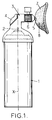
- FIG. 1 to which reference is first made, are schematically represented, in side view, the general arrangements in accordance with the invention of a portable first aid device for washing an eye and / or skin, in particular following a projection of a chemical agent or a thermal burn.
- This device comprises a liquid reservoir 1 which contains washing liquid under pressure (for example under a pressure of the order of 106 Pa) and which is shaped and arranged in any way appropriate to its function.
- the pressurized liquid consists of a liquid suitable for washing the eye or the skin (water or any suitable solution).
- the container 1 is equipped with an outlet valve which, being actuated for example by depressing the outlet nozzle 2, releases a spray of sprayed or atomized liquid.
- the reservoir 1 is of cylindrical shape of revolution and the outlet valve is arranged on its upper face (arrangement in "spray can").
- a device 3 for dispensing liquid which is functionally associated with the outlet valve to actuate the nozzle 2 thereof.
- This actuation function is symbolized, in FIG. 1, by an actuation button 4, the mechanical connection means between the button 4 and the end piece 2 not being shown, but may be of any type known to the 'Man of Art.
- Security means (not shown) can also be provided, for example in combination with button 4, to display the absence of prior use of the device.
- the dispensing device 3 ends with a liquid outlet nozzle 5, of approximately horizontal axis (throughout the description, the vertical axis X of the reservoir 1 will be referred to as, for its use as a sprayer, is held approximately vertically, and by extension horizontal axis any axis perpendicular to the X axis); however, it will be understood that the orientation of the axis of the nozzle 5 is not critical.
- a member 6 for adjusting the jet of liquid coming from the valve is provided a member 6 for adjusting the jet of liquid coming from the valve.
- This adjusting member 6 is arranged to be moved between two extreme positions, namely a first extreme position for which the nozzle projects a jet of finely divided or sprayed liquid or even atomized in the form of a mist and a second extreme position for which the nozzle delivers drops of liquid, in particular in the form of a substantially continuous flow of liquid.
- the adjusting member 6 can be produced for example in the form of a rotating ring actuating an internal mechanism located upstream of the nozzle 5.
- the jet of sprayed liquid is projected towards the eye to entrain, by trickling, any trace of a foreign product.
- the continuous flow of liquid it is intended to be collected in an eye-cup 7, so that the injured eye can be bathed completely by the liquid.
- the eyecup can be provided with a hole 8 in its lower part, so that the contaminated liquid flows through it in contact with the injured eye.
- the regulating member can adjust the power of the spray jet exiting from the nozzle 5.
- the outlet nozzle 5 can receive any suitable inclination other than horizontal, or even be vertical to facilitate the use of the eyecup.
- the apparatus and in particular the dispensing device 2 can be arranged in any way suitable for facilitating the use thereof, on the one hand, and for facilitating the manufacture thereof with minimum cost, of somewhere else.
- the device can be made, in its entirety or at least for the most part, out of plastic material.
- Means of manufacture or attachment may be provided (clip or fastening strip integral with the reservoir 1) so that the device can be kept awaiting use in a garment pocket or hung on the back of a pocket, fixed around an arm or leg, etc.
- a protective cap (not shown) can also be provided.
- the eyecup 7 may be integral with the nozzle 5 or even be removable; it is then placed on the nozzle, for example by fitting, only if necessary and is hitherto kept in reserve in a pocket attached to the reservoir.
- the adjustment member 6 can be significantly simplified by providing an adjustment member which would only have two functional positions corresponding respectively to the two aforementioned extreme positions, namely a spraying position and a continuous flow position.
- a third non-functional intermediate position can be provided in which the valve of the reservoir cannot be actuated, this third position, which constitutes a safety device, rendering the device inactive.
- the tank outlet valve may be actuated in a manner other than by means of an actuation button 4; in particular it may be the whole of the dispensing device 3 which can be arranged to be movable relative to the reservoir 1, either by rotation, or more commonly by vertical depression (that is to say along the axis X), to actuate the nozzle 2.
- actuation button 4 it may be the whole of the dispensing device 3 which can be arranged to be movable relative to the reservoir 1, either by rotation, or more commonly by vertical depression (that is to say along the axis X), to actuate the nozzle 2.
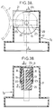
- FIGS. 2A and 2B a first embodiment of a dispensing device 31 arranged according to the arrangements which have just been indicated.
- the device 31 arranged according to the arrangements which have just been indicated.
- the device 31 comprises a body 9 suitable for covering the top of the reservoir and comprising means (not shown) cooperating with the end piece 2 to actuate the latter when it is pressed in relation to the reservoir 1.
- the body 9, in particular of revolution is shaped to retain a movable head 10, substantially cylindrical of revolution, so that it can rotate on itself between two extreme positions, for example by rotation through 180 °.
- the movable head 10, which is substantially coaxial with the axis X of the reservoir 1, is crossed by a bent conduit 11.
- This conduit opens on the underside of the head 10 by an inlet orifice 12 coaxial with the axis 10 and therefore located in look of the nozzle 2; the conduit 11 opens onto the side wall of the head 10 through an outlet orifice 13.
- the body 9 Opposite the orifice 13 when the head 10 is in each of the two aforementioned functional positions, in particular diametrically opposite as shown in FIGS. 2A and 2B, the body 9 has two outlet orifices 14 and 15 directed radially.
- the orifice 14 is arranged for the exit of a continuous flow of liquid and it can in particular be shaped in the form of a housing of relatively large section suitable for receiving by fitting the cylindrical foot 16 an eyelet 7.
- the movable head 10 is oriented so that the outlet orifice 13 of the conduit 11 is located opposite the outlet orifice 14 of the device 31.
- the outlet orifice 15 is shaped for the projection of a jet of sprayed liquid.
- the movable head 10 having rotated 180 ° relative to the position of FIG. 2A, the duct 11 has its outlet orifice 13 situated opposite the outlet orifice 15 of the device 31.
- the outlet orifice 14 being inactive, the eyecup 7 may possibly not be in place.
- the actuation of the nozzle 2 of the reservoir is carried out by pressing vertically on the device 31.
- Indicator means such as an arrow arranged on the upper face of the movable head 10, make it possible to identify the active output 14 or 15.
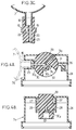
- FIGS 3A, 3B and 3C illustrate a preferred embodiment of the dispensing device designated here by the reference 32.
- the device comprises a body 17 suitable for being fitted onto the reservoir 1 and which has two inner cheeks 18 supporting the horizontal axis of rotation of a rotating head 20 in the form of a disc or a wheel.
- the body 17 is hollowed out at 21 upwards and on the side, facing the head 20, in correspondence with an angular sector of approximately 90 ° of said head.
- the rotating head 20 can be substantially flush with the level of the upper wall of the body 17, or even protrude substantially above the latter.
- the rotating head 20 is pierced with two substantially diametrical conduits 22 and 23, extending substantially 90 ° from one another, and offset axially with respect to one another so as not to communicate the one with the other.
- the conduit 22 ends with an outlet orifice 221 allowing the projection of a jet of sprayed liquid, while the conduit 23 ends with an outlet orifice 231 allowing a continuous flow of liquid. Thanks to this arrangement, one of the two conduits 22 or 23 can be brought selectively, by rotation of the head 20, in a vertical position approximately in the extension of the nozzle 2 of the valve of the reservoir 1.
- conduit 22 provided for the projection of a jet of liquid sprayed from its orifice 221 which is in the functional position above the nozzle 2. In this mode the liquid jet is projected upwards.
- the presence of the eyecup 7 at the end 231 of the other conduit 23, which is inactive, is optional.
- FIG. 3C only the head 20 shown in the second functional position is shown, that is to say with the conduit 23 situated vertically approximately in the extension of the end piece 2.
- the outlet port 231 is shaped to receive the tubular base 16 of the eyecup 7 which, here, opens upwards.
- the upper body 17 can, if desired, be shaped (in particular rounded) so that the rotating head 20 can be turned from one functional position to the other while the eyecup 7 remains in the position at the end of the corresponding conduit 23.
- the outlet orifices 221 and 231 of device 32 belong to the movable head 20, while in the previous device 31 (as well as in the following device 33) the outlet orifices are provided in the body.
- FIGS 4A and 4B illustrate yet another embodiment of the dispensing device, designated by the reference 33, which combines the provisions of the previous devices 31 and 32.
- the device 33 comprises a body 24 arranged to fit onto the top of the tank 1.
- the body 24 has two outlet orifices, 25 and 26, approximately opposite one another and arranged respectively for the supply of a continuous flow of liquid (outlet 25) and for the supply of a spray of liquid spray (outlet 26).
- the outlet orifice 25 is arranged to receive the tubular base 16 of the eyecup 7.
- the body 24 has two inner cheeks 27 supporting in rotation, by its horizontal axis 28, a rotating head 29 in the general form of a wheel.
- the body 24 is hollowed out, at its upper part, so that a small area of the head 29 is protruding for its actuation in rotation.
- the head 29 is crossed transversely by two bent conduits 30 and 31.
- the two conduits 30 and 31 respectively comprise two first sections 301 and 311 oriented approximately radially in the direction of the central axis of the head 29, being mutually inclined by approximately 45 °; the two sections 301 and 311 open at the lower part of the head 29 in a common chamber 32, open downwards extending angularly over approximately 45 °.
- the two conduits 30 and 31 also respectively comprise two second sections 302 and 312, at right angles to the respective first sections 301 and 311 and oriented radially by forming between them an angle of approximately 135 °; the two sections 302 and 312 open radially on the side wall of the movable head 29.
- FIGS. 4A and 4B By rotation of the movable head by approximately 45 °, one passes from a first functional position shown in FIGS. 4A and 4B in which the duct 30 is active (section 301 substantially vertical and approximately in alignment with the end piece 2 of the reservoir and substantially horizontal section 302 cooperating with the outlet orifice 25 provided with the eyelet 7) in the second functional position in which the duct 31 is active (section 311 substantially vertical and approximately in the extension of the nozzle 2 of the reservoir and substantially horizontal section 312 cooperating with the outlet orifice 26 for projecting a jet of sprayed liquid).
- the arrangement of the movable head is not limited to rotary heads and it is possible to envisage systems with tilting head, sliding head or the like.
Abstract
Description
La présente invention concerne des perfectionnements apportés aux appareils portatifs de premier secours pour le lavage d'un oeil et/ou de la peau, notamment à la suite d'une projection d'agent chimique (acide, base, solvant, toxique) ou d'une brûlure thermique.The present invention relates to improvements made to portable first aid devices for washing an eye and / or the skin, in particular following a projection of a chemical agent (acid, base, solvent, toxic) or '' a thermal burn.
On connaît divers types d'appareils pour le lavage d'un oeil accidenté, parmi lesquels les plus couramment utilisés sont :
- la fontaine occulaire composée d'une vasque dans laquelle est intégré au moins un gicleur ; le liquide libéré par le gicleur est en général de l'eau ;
- le réservoir rigide constitué par au moins un flacon auquel est raccordée une tubulure terminée par une oeillère ; le dispositif est lui-même maintenu à l'intérieur d'une enceinte plus ou moins étanche à la poussière; ce dispositif ne demande aucun branchement puisqu'il fonctionne par gravité et les flacons, ou au moins un flacon, peuvent contenir un produit spécifique, par exemple un anti-acide.
- the eye fountain composed of a basin in which is integrated at least one nozzle; the liquid released by the nozzle is generally water;
- the rigid reservoir consisting of at least one bottle to which is connected a tubing terminated by a blinker; the device is itself kept inside a more or less dustproof enclosure; this device does not require any connection since it works by gravity and the bottles, or at least one bottle, may contain a specific product, for example an antacid.
Les dispositifs précités présentent divers inconvénients :
- ils se trouvent à des postes fixes et ne peuvent donc être portés individuellement, ce qui allonge le temps d'intervention sur l'oeil accidenté ; or un oeil atteint par un élément chimique ou par une brûlure thermique doit être lavé le plus rapidement possible pour limiter l'action et la pénétration du produit et éviter ainsi sa destruction partielle ou totale ;
- une personne dont un oeil a été atteint par un agent chimique n'a plus son acuité visuelle normale et doit se diriger éventuellement seule jusqu'au dispositif de lavage installé à poste fixe, ce qui risque d'entraîner encore un allongement du temps d'intervention ;
- le dispositif de lavage, qui n'est pas individuel, peut contribuer à une transmission microbienne ;
- l'action du jet de liquide dont l'intensité n'est pas réglable peut être traumatisante sur un oeil blessé.
- they are located at fixed positions and cannot therefore be worn individually, which lengthens the intervention time on the injured eye; however, an eye affected by a chemical element or by a thermal burn must be washed as quickly as possible to limit the action and penetration of the product and thus avoid its partial or total destruction;
- a person whose eye has been hit by a chemical agent no longer has his normal visual acuity and must eventually go alone to the washing device installed at a fixed station, which risks further prolonging the time of intervention;
- the washing device, which is not individual, can contribute to microbial transmission;
- the action of the jet of liquid whose intensity is not adjustable can be traumatic on an injured eye.
On connaît également un dispositif portatif composé d'une poche souple en matière plastique contenant le produit de lavage et d'une tubulure terminée par une oeillère ; ce dispositif fonctionne de la même façon que précédemment par gravité. Toutefois, ce dispositif portatif présente l'inconvénient que la poche en matière plastique souple risque d'éclater ou d'être percée lors de sa manipulation. De plus sa manipulation n'est pas aisée pour une personne atteinte aux yeux.There is also known a portable device composed of a flexible plastic bag containing the washing product and of a tubing terminated by a blind eye; this device works in the same way as previously by gravity. However, this portable device has the disadvantage that the flexible plastic bag may burst or be pierced during handling. In addition, its handling is not easy for a person affected by the eyes.
On connaît également (document FR-A-2 682 036) un flacon portable individuel muni d'une ouverture de grande dimension conformée pour épouser le contour de l'oeil ; le flacon est rempli d'une solution de lavage et est obturé de façon étanche jusqu'à l'emploi. Toutefois, ce flacon à usage unique ne contient qu'une quantité de liquide juste suffisante pour un premier lavage d'un oeil accidenté ; en outre, il ne permet d'effectuer qu'un bain de l'oeil et n'est pas agencé pour projeter du liquide pulvérisé sur l'oeil afin d'accéler une élimination d'un produit étranger.Also known (document FR-A-2 682 036) is an individual portable bottle provided with a large opening shaped to conform to the eye contour; the bottle is filled with a washing solution and is sealed until use. However, this single-use bottle only contains a sufficient amount of liquid for a first wash of an injured eye; in addition, it only makes it possible to carry out an eye bath and is not designed to project sprayed liquid onto the eye in order to accelerate the elimination of a foreign product.
Pour ce qui est maintenant du lavage de la peau accidentée, notamment par une projection d'un agent chimique ou par une brûlure, il est recommandé de projeter de l'eau sous forme d'une pulvérisation ou d'un brouillard qui humidifie de façon régulière et relativement homogène tout en entraînant une moindre consommation de liquide. Mais par contre, il est très difficile de projeter un jet de liquide, qu'il s'agisse d'un jet continu ou d'un jet de liquide pulvérisé, directement dans un oeil en raison du réflexe d'occlusion palpébral.Now for washing damaged skin, in particular by spraying with a chemical agent or by a burn, it is recommended to spray water in the form of a spray or mist which moistens regular and relatively homogeneous while leading to a lower consumption of liquid. But on the other hand, it is very difficult to project a jet of liquid, whether it is a continuous jet or a jet of sprayed liquid, directly into an eye because of the palpebral occlusion reflex.
L'invention a essentiellement pour but de proposer un dispositif perfectionné qui écarte les inconvénients précités des dispositifs actuellement connus et qui donne mieux satisfaction aux diverses exigences de la pratique.The object of the invention is essentially to propose an improved device which eliminates the aforementioned drawbacks of the devices currently known and which gives better satisfaction to the various requirements of practice.
A ces fins, un appareil portatif de premier secours tel que mentionné au préambule, étant agencé conformément à l'invention, se caractérise essentiellement en ce que le dispositif dispensateur comporte un organe de réglage du jet de liquide sortant de ladite valve, lequel organe est apte à être réglé depuis une première position extrême pour laquelle le dispositif dispensateur projette un jet de liquide finement pulvérisé jusqu'à une seconde position extrême pour laquelle le dispositif dispensateur dispense un écoulement sensiblement continu de liquide de lavage ; en outre le dispositif dispensateur comporte une oeillère fonctionnellement active au moins lorsque l'organe de réglage est dans la susdite seconde position extrême pour recueillir le liquide dispensé en écoulement continu afin d'autoriser un bain de l'oeil accidenté.For these purposes, a portable first aid device as mentioned in the preamble, being arranged in accordance with the invention, is essentially characterized in that the dispensing device comprises a member for adjusting the jet of liquid leaving said valve, which member is able to be adjusted from a first extreme position for which the dispensing device projects a jet of finely atomized liquid to a second extreme position for which the dispensing device dispenses a substantially continuous flow of washing liquid; in addition, the dispensing device comprises a functionally active eyelet at least when the adjustment member is in the aforesaid second extreme position for collecting the liquid dispensed in continuous flow in order to allow a bath for the injured eye.
Ainsi constitué, l'appareil de l'invention permet d'adapter le processus de lavage en fonction de la localisation (oeil et/ou peau) et de l'importance du dommage et en particulier il offre le choix entre une pulvérisation du liquide de lavage qui, en s'écoulant sur le visage, entraîne avec lui le produit étranger ou bien un lavage total par bain de l'oeil dans une oeillère qui offre l'avantage d'un contact complet et total du liquide de lavage avec la totalité de la surface de l'oeil et de la paupière.Thus constituted, the apparatus of the invention makes it possible to adapt the washing process according to the location (eye and / or skin) and the extent of the damage and in particular it offers the choice between spraying the washing which, flowing over the face, carries with it the foreign product or else a total washing by bathing the eye in an eye-cup which offers the advantage of complete and total contact of the washing liquid with the whole from the surface of the eye and the eyelid.
En outre, il s'agit d'un appareil qui peut, techniquement, être réalisé avec une forme et des dimensions le rendant aisément portable par un individu (soit dans une poche de vêtement ; soit accroché extérieurement ou intérieusement sur une partie de vêtement), en demeurant en permanence à portée de main et prêt à l'emploi.In addition, it is a device which can, technically, be made with a shape and dimensions making it easily portable by an individual (either in a garment pocket; either hung externally or internally on a part of clothing) , always being close at hand and ready to use.
Dans le but de simplifier au maximum la structure de l'appareil et donc de permettre une fabrication relativement peu coûteuse autorisant une large diffusion de ce type d'appareil, on prévoit de préférence que l'organe de réglage soit agencé pour occuper sélectivement seulement deux positions fonctionnelles correspondant aux deux susdites positions extrêmes. Eventuellement, on peut en outre faire en sorte que l'organe de réglage soit agencé pour pouvoir occuper une troisième position intermédiaire, non fonctionnelle, dans laquelle la valve de sortie du réservoir ne peut pas être actionnée à l'ouverture.In order to simplify the structure of the device as much as possible and therefore to allow relatively inexpensive manufacturing allowing wide distribution of this type of device, provision is preferably made for the adjusting member to be arranged to selectively occupy only two functional positions corresponding to the two aforementioned extreme positions. Optionally, it is also possible for the adjustment member to be arranged so as to be able to occupy a third intermediate, non-functional position, in which the outlet valve of the reservoir cannot be actuated upon opening.
En pratique, il est intéressant, dans une telle réalisation simplifiée, que le dispositif dispensateur comporte une tête mobile susceptible d'occuper sélectivement les deux susdites positions fonctionnelles, et que cette tête mobile soit traversée par au moins un conduit qui posséde un orifice d'entrée susceptible de recevoir le liquide sortant de la valve de sortie du réservoir et qui est apte à coopérer sélectivement avec deux orifices de sortie respectifs agencés, le premier, pour projeter un jet de liquide finement pulvérisé et, le second, pour recevoir ou constituer une oeillère et délivrer un écoulement continu de liquide dans celle-ci. Avantageusement alors, la tête mobile est sensiblement cylindrique de révolution et est montée à rotation dans le corps du dispositif dispensateur.In practice, it is advantageous, in such a simplified embodiment, that the dispensing device comprises a movable head capable of selectively occupying the two aforementioned functional positions, and that this movable head is traversed by at least one conduit which has an orifice. inlet capable of receiving the liquid leaving the tank outlet valve and which is capable of cooperating selectively with two respective outlet orifices arranged, the first, for projecting a jet of finely sprayed liquid and, the second, for receiving or constituting a eyecup and deliver a continuous flow of liquid therein. Advantageously then, the movable head is substantially cylindrical of revolution and is mounted for rotation in the body of the dispensing device.
Bien qu'il soit possible, sur le strict plan technique, de réaliser un dispositif dispensateur relativement compact apte à coiffer la tête d'un bidon de liquide de lavage sous pression, l'oeillère constitue un organe formant une saillie relativement volumineuse et dont les dimensions ne peuvent pas être arbitrairement réduites eu égard aux dimensions morphologiques de l'oeil humain. On peut donc alors prévoir de réaliser l'oeillère sous forme d'une pièce séparée qui est emmanchée de façon amovible dans le second orifice et s'étend approximativement radialement sur la tête mobile. On peut alors envisager le montage de l'oeillère en usine, l'appareil étant alors commercialisé sous sa forme complète, avec l'oeillère en place, mais étant relativement encombrant, ou bien la commercialisation de l'appareil dans une configuration moins encombrante avec l'oeillère non montée (disposée par exemple dans une pochette fixée au réservoir de liquide sous pression).Although it is technically possible to make a relatively compact dispensing device capable of covering the head of a can of pressurized washing liquid, the eyecup constitutes an organ forming a relatively bulky projection and the dimensions cannot be arbitrarily reduced with regard to the morphological dimensions of the human eye. We can therefore plan to make the eyecup in the form of a separate piece which is removably fitted into the second orifice and extends approximately radially on the movable head. We can then consider mounting the eyecup in the factory, the device then being marketed in its complete form, with the eyecup in place, but being relatively bulky, or else the marketing of the device in a less bulky configuration with the unassembled eyecup (placed for example in a pocket fixed to the pressurized liquid tank).
Dans un mode de réalisation qui ne semble pas devoir présenter de notables difficultés de fabrication en grande série et qui est facile à utiliser, la tête mobile est montée à rotation autour d'un axe sensiblement vertical et les deux orifices de sortie sont situés sur la paroi latérale de la tête mobile avec des axes respectifs sensiblement horizontaux ; on peut alors prévoir que les deux orifices de sortie soient sensiblement diamétralement opposés et que le passage de la tête mobile d'une position fonctionnelle à l'autre corresponde à une rotation d'environ 180°.In an embodiment which does not seem to present significant difficulties in mass production and which is easy to use, the movable head is mounted for rotation about a substantially vertical axis and the two outlet orifices are located on the side wall of the movable head with respective substantially horizontal axes; it can then be provided that the two outlet orifices are substantially diametrically opposite and that the passage of the movable head from one functional position to the other corresponds to a rotation of approximately 180 °.
Dans un autre mode de réalisation possible, la tête mobile est montée à rotation autour d'un axe sensiblement horizontal, et cette tête mobile est, au moins pour sa plus grande partie, encastrée dans le corps du dispositif dispensateur, selon une configuration analogue à une molette. Dans un premier exemple de réalisation préféré, on prévoit que la rotation rotation de la tête mobile pour amener un orifice de sortie sélectivement en position fonctionnelle est d'environ 90° et que l'orifice de sortie rendu actif soit disposé avec son axe sensiblement vertical; dans un second exemple de réalisation, on prévoit que la rotation de la tête mobile de l'une à l'autre des deux positions fonctionnelles est d'environ 45°, que les deux conduits sont conformés de manière que les axes de leurs orifices de sortie dirigés radialement soient mutuellement écartés d'environ 135°, et que les orifices de sortie d'écoulement continu et de pulvérisation soient sensiblement alignés et diamétralement opposés de part et d'autre de la tête mobile.In another possible embodiment, the movable head is mounted for rotation about a substantially horizontal axis, and this movable head is, at least for the most part, embedded in the body of the dispensing device, in a configuration analogous to a wheel. In a first preferred exemplary embodiment, it is provided that the rotation rotation of the movable head to bring an outlet orifice selectively to the functional position is approximately 90 ° and that the outlet orifice made active is arranged with its substantially vertical axis. ; in a second embodiment, it is provided that the rotation of the movable head from one to the other of the two functional positions is approximately 45 °, that the two conduits are shaped so that the axes of their orifices of radially directed outlets are spaced approximately 135 ° apart, and that the continuous flow and spray outlet ports are substantially aligned and diametrically opposed on either side of the movable head.
L'invention sera mieux comprise à la lecture de la description détaillée qui suit de certains modes de réalisation donnés uniquement à titre d'exemples non limitatifs. Dans cette description, on se réfère aux dessins annexés sur lesquels :
- la figure 1 est une vue de côté schématique illustrant la conception générale d'un appareil perfectionné conforme à l'invention ;
- les figures 2A et 2B sont des vues en coupe diamétrale d'un premier mode de réalisation du dispositif dispensateur, montré respectivement dans ses deux positions fonctionnelles, apte à équiper l'appareil de l'invention ;
- la figure 3A est une vue de côté, en coupe selon la ligne BB de la figure 3B, d'un mode de réalisation préféré du dispositif dispensateur montré dans une première position fonctionnelle ;
- la figure 3B est une vue de face, en coupe selon la ligne AA de la figure 3A, du dispositif de la figure 3A montré dans la même position fonctionnelle ;
- la figure 3C est une vue de face, en coupe diamétrale, de la seule tête mobile du dispositif des figures 3A et 3B montrée dans l'autre position fonctionnelle; et
- les figures 4A et 4B sont des vues en coupe, respectivement de côté et de face, d'encore un autre mode de réalisation du dispositif dispenssateur montré dans une des positions fonctionnelles.
- Figure 1 is a schematic side view illustrating the general design of an improved apparatus according to the invention;
- FIGS. 2A and 2B are views in diametral section of a first embodiment of the dispensing device, shown respectively in its two functional positions, able to equip the device of the invention;
- FIG. 3A is a side view, in section along the line BB of FIG. 3B, of a preferred embodiment of the dispensing device shown in a first functional position;
- Figure 3B is a front view, in section along line AA of Figure 3A, of the device of Figure 3A shown in the same functional position;
- FIG. 3C is a front view, in diametral section, of the single movable head of the device in FIGS. 3A and 3B shown in the other functional position; and
- Figures 4A and 4B are sectional views, respectively from the side and from the front, of yet another embodiment of the dispensing device shown in one of the functional positions.
Sur la figure 1 à laquelle on se réfère tout d'abord sont représentées schématiquement, en vue de côté, les dispositions générales conformes à l'invention d'un appareil portatif de premier secours pour le lavage d'un oeil et/ou de la peau, notamment à la suite d'une projection d'un agent chimique ou d'une brûlure thermique. Cet appareil comporte un réservoir de liquide 1 qui contient du liquide de lavage sous pression (par exemple sous une pression de l'ordre de 10⁶ Pa) et qui est conformé et agencé de toute façon appropriée à sa fonction. Le liquide sous pression est constitué d'un liquide approprié pour le lavage de l'oeil ou de la peau (eau ou toute solution appropriée). Le récipient 1 est équipé d'une valve de sortie qui, étant actionnée par exemple par enfoncement de l'embout de sortie 2, libère un jet de liquide pulvérisé ou atomisé.In FIG. 1, to which reference is first made, are schematically represented, in side view, the general arrangements in accordance with the invention of a portable first aid device for washing an eye and / or skin, in particular following a projection of a chemical agent or a thermal burn. This device comprises a
Dans un mode de réalisation courant tel que représenté à la figure 1, le réservoir 1 est de forme cylindrique de révolution et la valve de sortie est disposée sur sa face supérieure (agencement en "bombe" pulvérisatrice).In a current embodiment as shown in FIG. 1, the
Sur le haut du réservoir 1 est fixé, par exemple par emboîtement, un dispositif 3 dispensateur de liquide qui est associé fonctionnellement avec la valve de sortie pour actionner l'embout 2 de celle-ci. Cette fonction d'actionnement est symbolisée, sur la figure 1, par un bouton d'actionnement 4, les moyens de liaison mécanique entre le bouton 4 et l'embout 2 n'étant pas montrés, mais pouvant être de tout type connus de l'Homme de l'Art. Des moyens de sécurité (non montrés) peuvent être prévus en outre, par exemple en association avc le bouton 4, pour visualiser l'absence d'utilisation antérieure de l'appareil.On the top of the
Le dispositif dispensateur 3 se termine par une buse de sortie de liquide 5, d'axe approximativement horizontal (dans toute la description on dénommera axe vertical l'axe X du réservoir 1 qui, pour son utilisation en pulvérisateur, est tenu approximativement verticalement, et par extension axe horizontal tout axe perpendiculaire à l'axe X) ; toutefois, on comprendra que l'orientation de l'axe de la buse 5 n'est pas critique.The dispensing device 3 ends with a liquid outlet nozzle 5, of approximately horizontal axis (throughout the description, the vertical axis X of the
En arrière de la buse de sortie 5 est prévu un organe 6 de réglage du jet de liquide en provenance de la valve. Cet organe de réglage 6 est agencé pour être déplacé entre deux positions extrêmes, à savoir une première position extrême pour laquelle la buse projette un jet de liquide finement divisé ou pulvérisé ou encore atomisé sous forme d'un brouillard et une seconde position extrême pour laquelle la buse délivre des gouttes de liquide, notamment sous forme d'un écoulement sensiblement continu de liquide.Behind the outlet nozzle 5 is provided a member 6 for adjusting the jet of liquid coming from the valve. This adjusting member 6 is arranged to be moved between two extreme positions, namely a first extreme position for which the nozzle projects a jet of finely divided or sprayed liquid or even atomized in the form of a mist and a second extreme position for which the nozzle delivers drops of liquid, in particular in the form of a substantially continuous flow of liquid.
L'organe de réglage 6 peut être réalisé par exemple sous forme d'une bague tournante actionnant un mécanisme intérieur situé en amont de la buse 5.The adjusting member 6 can be produced for example in the form of a rotating ring actuating an internal mechanism located upstream of the nozzle 5.
Le jet de liquide pulvérisé est projeté en direction de l'oeil pour entraîner, en ruisselant, toute trace d'un produit étranger.The jet of sprayed liquid is projected towards the eye to entrain, by trickling, any trace of a foreign product.
Pour ce qui est de l'écoulement continu de liquide, il est destiné à être recueilli dans une oeillère 7, de manière que l'oeil accidenté puisse être baigné de façon complète par le liquide. L'oeillère peut être munie d'un trou 8 à sa partie inférieure, afin que s'écoule par celui-ci le liquide contaminé au contact de l'oeil accidenté.As regards the continuous flow of liquid, it is intended to be collected in an eye-cup 7, so that the injured eye can be bathed completely by the liquid. The eyecup can be provided with a
Entre les deux susdites positions extrêmes, l'organe de réglage peut ajuster la puissance du jet de pulvérisation sortant de la buse 5.Between the two aforementioned extreme positions, the regulating member can adjust the power of the spray jet exiting from the nozzle 5.
On comprendra que pour faciliter la projection du jet de pulvérisation en direction de l'oeil, la buse de sortie 5 peut recevoir toute inclinaison appropriée autre qu'horizontale, voire même être verticale pour faciliter l'utilisation de l'oeillère.It will be understood that, to facilitate the projection of the spray jet towards the eye, the outlet nozzle 5 can receive any suitable inclination other than horizontal, or even be vertical to facilitate the use of the eyecup.
D'une façon générale, l'appareil, et en particulier le dispositif dispensateur 2, peuvent être agencés de toute manière propre à en faciliter l'utilisation, d'une part, et à en faciliter la fabrication avec un coût minimum, d'autre part. Notamment, le dispositif peut être fabriqué, dans son intégralité ou au moins dans sa majeure partie, en matière plastique. On peut prévoir des moyens de fabrication ou d'accrochage (agrafe ou bande de fixation solidaire du réservoir 1) pour que l'appareil puisse être tenu en attente d'utilisation dans une poche de vêtement ou accroché au revers d'une poche, fixé autour d'un bras ou d'une jambe, etc. Un capuchon protecteur (non montré) peut être également prévu. L'oeillère 7 peut être solidaire de la buse 5 ou encore être amovible ; elle n'est alors mise en place sur la buse, par exemple par emmanchement, qu'en cas de nécessité et est jusque-là tenu en réserve dans une pochette fixée au réservoir.In general, the apparatus, and in particular the dispensing
Dans le cas où l'on envisage plus particulièrement un appareil de très grande diffusion qui doit donc pouvoir être fabriqué à moindre coût, on peut simplifier notablement l'organe de réglage 6 en prévoyant un organe de réglage qui ne disposerait que de seulement deux positions fonctionnelles correspondant respectivement aux deux positions extrêmes précitées, à savoir une position pulvérisation et une position écoulement continu. Eventuellement, une troisième position intermédiaire, non fonctionnelle, peut être prévue dans laquelle la valve du réservoir ne peut pas être actionnée, cette troisième position, qui constitue une sécurité, rendant l'appateil inactif.In the case where a device of very great distribution is considered more particularly which must therefore be able to be manufactured at a lower cost, the adjustment member 6 can be significantly simplified by providing an adjustment member which would only have two functional positions corresponding respectively to the two aforementioned extreme positions, namely a spraying position and a continuous flow position. Optionally, a third non-functional intermediate position can be provided in which the valve of the reservoir cannot be actuated, this third position, which constitutes a safety device, rendering the device inactive.
Toujours pour simplifier à la fois l'utilisation et la fabrication du dispositif dispensateur, on peut prévoir que la valve de sortie du réservoir soit actionnée d'une autre manière que par l'intermédiaire d'un bouton d'actionnement 4 ; en particulier ce peut être l'ensemble du dispositif dispensateur 3 qui peut être agencé pour être mobile par rapport au réservoir 1, soit par rotation, soit plus couramment par enfoncement vertical (c'est-à-dire selon l'axe X), pour actionner l'embout 2. De tels agencements sont connus de l'Homme de l'Art.Still to simplify both the use and the manufacture of the dispensing device, provision may be made for the tank outlet valve to be actuated in a manner other than by means of an
Aux figures 2A et 2B est représenté un premier mode de réalisation d'un dispositif dispensateur 3₁ agencé selon les dispositions qui viennent d'être indiquées. Le dispositif 3₁ agencé selon les dispositions qui viennent d'être indiquées. Le dispositif 3₁ comporte un corps 9 propre à coiffer le haut du réservoir et comportant des moyens (non représentés) coopérant avec l'embout 2 pour actionner celui-ci lorsqu'il est enfoncé par rapport au réservoir 1. Le corps 9, notamment de révolution, est conformé pour retenir une tête mobile 10, sensiblement cylindrique de révolution, de manière que celle-ci puisse tourner sur elle-même entre deux positions extrêmes, par exemple par rotation sur 180°. La tête mobile 10, qui est sensiblement coaxiale à l'axe X du réservoir 1, est traversée par un conduit coudé 11. Ce conduit s'ouvre sur la face inférieure de la tête 10 par un orifice d'entrée 12 coaxial à l'axe 10 et donc situé en regard de l'embout 2 ; le conduit 11 débouche sur la paroi latérale de la tête 10 par un orifice de sortie 13.In Figures 2A and 2B is shown a first embodiment of a dispensing
En regard de l'orifice 13 lorsque la tête 10 est dans chacune des deux positions fonctionnelles précitées, en particulier diamétralement opposées comme représenté sur les figures 2A et 2B, le corps 9 comporte deux orifices de sortie 14 et 15 dirigés radialement.Opposite the
Comme représenté sur la figure 2A, l'orifice 14 est agencé en vue de la sortie d'un écoulement continu de liquide et il peut notamment être conformé sous forme d'un logement de relativement grande section propre à recevoir par emmanchement le pied cylindrique 16 d'une oeillère 7. Dans la position fonctionnelle représentée à la figure 2A, la tête mobile 10 est orientée de manière que l'orifice de sortie 13 du conduit 11 soit situé en regard de l'orifice de sortie 14 du dispositif 3₁.As shown in FIG. 2A, the
Comme représenté maintenant sur la figure 2B, l'orifice de sortie 15 est conformé pour la projection d'un jet de liquide pulvérisé. Dans cette position, la tête mobile 10 ayant tournée de 180° par rapport à la position de la figure 2A, le conduit 11 a son orifice de sortie 13 situé en regard de l'orifice de sortie 15 du dispositif 3₁. L'orifice de sortie 14 étant inactif, l'oeillère 7 peut éventuellement ne pas être en place.As now shown in FIG. 2B, the
L'actionnement de l'embout 2 du réservoir s'effectue en appuyant verticalement sur le dispositif 3₁.The actuation of the
Des moyens indicateurs, tels qu'une flèche disposée sur la face supérieure de la tête mobile 10, permettent de repérer la sortie active 14 ou 15.Indicator means, such as an arrow arranged on the upper face of the
Les figures 3A, 3B et 3C illustrent un mode de réalisation préféré du dispositif dispensateur désigné ici par la référence 3₂. Le dispositif comporte un corps 17 propre à être emboîté sur le réservoir 1 et qui présente deux joues intérieures 18 supportant l'axe horizontal de rotation d'une tête tournante 20 en forme de disque ou de molette. Le corps 17 est évidé en 21 vers le haut et sur le côté, en regard de la tête 20, en correspondance avec un secteur angulaire d'environ 90° de ladite tête. La tête tournante 20 peut affleurer sensiblement le niveau de la paroi supérieure du corps 17, voire même dépasser sensiblement au-dessus de celle-ci. La tête tournante 20 est percée de deux conduits sensiblement diamétraux 22 et 23, s'étendant sensiblement à 90° l'un de l'autre, et décalés axialement l'un par rapport à l'autre de manière à ne pas communiquer l'un avec l'autre. Le conduit 22 se termine par un orifice de sortie 22₁ permettant la projection d'un jet de liquide pulvérisé, tandis que le conduit 23 se termine par un orifice de sortie 23₁ permettant un écoulement continu de liquide. Grâce à cet agencement, on peut amener sélectivement l'un des deux conduits 22 ou 23, par rotation de la tête 20, en position verticale approximativement dans le prolongement de l'embout 2 de la valve du réservoir 1.Figures 3A, 3B and 3C illustrate a preferred embodiment of the dispensing device designated here by the
Dans la position représentée aux figures 3A et 3B, c'est le conduit 22 prévu pour la projection d'un jet de liquide pulvérisé à partir de son orifice 22₁ qui est en position fonctionnelle au-dessus de l'embout 2. Dans ce mode de réalisation le jet de liquide est projeté vers le haut. La présence de l'oeillère 7 à l'extrémité 23₁ de l'autre conduit 23, qui est inactif, est facultative.In the position shown in Figures 3A and 3B, it is the
Sur la figure 3C, seule est montrée la tête 20 disposée dans la seconde position fonctionnelle, c'est-à-dire avec le conduit 23 situé verticalement approximativement dans le prolongement de l'embout 2. A l'extrémité supérieure du conduit 23, l'orifice de sortie 23₁ est conformé pour recevoir le pied tubulaire 16 de l'oeillère 7 qui, ici, s'ouvre vers le haut.In FIG. 3C, only the
On notera que le haut du corps 17 peut, si on le souhaite, être conformé (notamment arrondi) de manière que la tête tournante 20 puisse être tournée d'une position fonctionnelle à l'autre alors que l'oeillère 7 demeure en position à l'extrémité du conduit 23 correspondant.It will be noted that the
On notera également que, dans ce mode de réalisation, les orifices de sortie 22₁ et 23₁ di dispositif 3₂ appartiennent à la tête mobile 20, tandis que, dans le dispositif précédent 3₁ (ainsi que dans le dispositif suivant 3₃) les orifices de sortie sont prévus dans le corps.It will also be noted that, in this embodiment, the
Les figures 4A et 4B illustrent encore un autre mode de réalisation du dispositif dispensateur, désigné par la référence 3₃, qui combine les dispositions des précédents dispositifs 3₁ et 3₂. Le dispositif 3₃ comporte un corps 24 agencé pour s'emboîter sur le haut du réservoir 1. Le corps 24 comporte deux orifices de sortie, 25 et 26, approximativement opposés l'un à l'autre et agencés respectivement pour la fourniture d'un écoulement continu de liquide (orifice de sortie 25) et pour la fourniture d'un jet de liquide pulvérisé (orifice de sortie 26). L'orifice de sortie 25 est, là encore, agencé pour recevoir le pied tubulaire 16 de l'oeillère 7.Figures 4A and 4B illustrate yet another embodiment of the dispensing device, designated by the
Le corps 24 possède deux joues intérieures 27 supportant à rotation, par son axe horizontal 28, une tête tournante 29 en forme générale de molette. Le corps 24 est évidé, à sa partie supérieure, de manière qu'une petite zone de la tête 29 soit saillante en vue de son actionnement en rotation. La tête 29 est traversée transversalement par deux conduits coudés 30 et 31. Les deux conduits 30 et 31 comportent respectivement deux premiers tronçons 30₁ et 31₁ orientés approximativement radialement en direction de l'axe central de la tête 29, en étant mutuellement inclinés d'environ 45° ; les deux tronçons 30₁ et 31₁ débouchent à la partie inférieure de la tête 29 dans une chambre commune 32, ouverte vers le bas s'étendant angulairement sur environ 45°. Les deux conduits 30 et 31 comportent également respectivement deux seconds tronçons 30₂ et 31₂, à angle droit avec les premiers tronçons respectifs 30₁ et 31₁ et orientés radialement en formant entre eux un angle d'environ 135° ; les deux tronçons 30₂ et 31₂ débouchent radialement sur la paroi latérale de la tête mobile 29.The
Par rotation de la tête mobile d'environ 45°, on passe d'une première position fonctionnelle montrée aux figures 4A et 4B dans laquelle le conduit 30 est actif (tronçon 30₁ sensiblement vertical et approximativement dans l'alignement de l'embout 2 du réservoir et tronçon 30₂ sensiblement horizontal coopérant avec l'orifice de sortie 25 muni de l'oeillère 7) à la seconde position fonctionnelle dans laquelle le conduit 31 est actif (tronçon 31₁ sensiblement vertical et approximativement dans le prolongement de l'embout 2 du réservoir et tronçon 31₂ sensiblement horizontal coopérant avec l'orifice de sortie 26 de projection d'un jet de liquide pulvérisé).By rotation of the movable head by approximately 45 °, one passes from a first functional position shown in FIGS. 4A and 4B in which the
Bien entendu, l'agencement de la tête mobile n'est restreinte à des tête rotatives et il est possible d'envisager des systèmes à tête basculante, à tête coulissante ou autres.Of course, the arrangement of the movable head is not limited to rotary heads and it is possible to envisage systems with tilting head, sliding head or the like.
Comme il va de soi et comme il résulte déjà de ce qui précède, l'invention ne se limite nullement à ceux de ses modes d'application et de réalisation qui ont été plus particulièrement envisagés ; elle en embrasse au contraire toutes les variantes.As is obvious and as already follows from the above, the invention is in no way limited to those of its modes of application and embodiments which have been more particularly envisaged; on the contrary, it embraces all its variants.
Claims (12)
Priority Applications (3)
| Application Number | Priority Date | Filing Date | Title |
|---|---|---|---|
| ES94401205T ES2123106T3 (en) | 1994-06-01 | 1994-06-01 | PORTABLE FIRST AID APPARATUS FOR EYE AND / OR SKIN WASHING. |
| DE69413673T DE69413673T2 (en) | 1994-06-01 | 1994-06-01 | Portable emergency device for washing an eye and / or skin |
| EP94401205A EP0685218B1 (en) | 1994-06-01 | 1994-06-01 | First-aid portable apparatus for washing an eye and/or the skin |
Applications Claiming Priority (1)
| Application Number | Priority Date | Filing Date | Title |
|---|---|---|---|
| EP94401205A EP0685218B1 (en) | 1994-06-01 | 1994-06-01 | First-aid portable apparatus for washing an eye and/or the skin |
Publications (2)
| Publication Number | Publication Date |
|---|---|
| EP0685218A1 true EP0685218A1 (en) | 1995-12-06 |
| EP0685218B1 EP0685218B1 (en) | 1998-09-30 |
Family
ID=8218008
Family Applications (1)
| Application Number | Title | Priority Date | Filing Date |
|---|---|---|---|
| EP94401205A Expired - Lifetime EP0685218B1 (en) | 1994-06-01 | 1994-06-01 | First-aid portable apparatus for washing an eye and/or the skin |
Country Status (3)
| Country | Link |
|---|---|
| EP (1) | EP0685218B1 (en) |
| DE (1) | DE69413673T2 (en) |
| ES (1) | ES2123106T3 (en) |
Cited By (3)
| Publication number | Priority date | Publication date | Assignee | Title |
|---|---|---|---|---|
| WO2001045632A1 (en) * | 1999-12-22 | 2001-06-28 | Hans Josefson | An eye-rinsing device |
| ITUB20153910A1 (en) * | 2015-09-25 | 2017-03-25 | Flaem Nuova Spa | Ophthalmic adapter and relative kit for vibrating mesh portable nebulizer |
| CN111150637A (en) * | 2020-01-03 | 2020-05-15 | 王莹 | Portable eye-washing sprayer |
Families Citing this family (1)
| Publication number | Priority date | Publication date | Assignee | Title |
|---|---|---|---|---|
| DE202009007205U1 (en) | 2009-05-19 | 2009-10-15 | Plum A/S | eyewash |
Citations (3)
| Publication number | Priority date | Publication date | Assignee | Title |
|---|---|---|---|---|
| DE1926796A1 (en) * | 1968-05-27 | 1970-03-19 | Dudiuyt Jean Paul | Aerosol compsn. and container |
| FR2207729A1 (en) * | 1972-11-24 | 1974-06-21 | Schmid Inc Julius | |
| FR2682036A1 (en) | 1991-10-03 | 1993-04-09 | Prevor International Sarl | Portable individual apparatus for washing an eye, especially an injured eye |
-
1994
- 1994-06-01 ES ES94401205T patent/ES2123106T3/en not_active Expired - Lifetime
- 1994-06-01 DE DE69413673T patent/DE69413673T2/en not_active Expired - Lifetime
- 1994-06-01 EP EP94401205A patent/EP0685218B1/en not_active Expired - Lifetime
Patent Citations (3)
| Publication number | Priority date | Publication date | Assignee | Title |
|---|---|---|---|---|
| DE1926796A1 (en) * | 1968-05-27 | 1970-03-19 | Dudiuyt Jean Paul | Aerosol compsn. and container |
| FR2207729A1 (en) * | 1972-11-24 | 1974-06-21 | Schmid Inc Julius | |
| FR2682036A1 (en) | 1991-10-03 | 1993-04-09 | Prevor International Sarl | Portable individual apparatus for washing an eye, especially an injured eye |
Cited By (4)
| Publication number | Priority date | Publication date | Assignee | Title |
|---|---|---|---|---|
| WO2001045632A1 (en) * | 1999-12-22 | 2001-06-28 | Hans Josefson | An eye-rinsing device |
| ITUB20153910A1 (en) * | 2015-09-25 | 2017-03-25 | Flaem Nuova Spa | Ophthalmic adapter and relative kit for vibrating mesh portable nebulizer |
| CN111150637A (en) * | 2020-01-03 | 2020-05-15 | 王莹 | Portable eye-washing sprayer |
| CN111150637B (en) * | 2020-01-03 | 2022-05-20 | 王莹 | Portable eye washing sprayer |
Also Published As
| Publication number | Publication date |
|---|---|
| DE69413673T2 (en) | 1999-06-10 |
| EP0685218B1 (en) | 1998-09-30 |
| ES2123106T3 (en) | 1999-01-01 |
| DE69413673D1 (en) | 1998-11-05 |
Similar Documents
| Publication | Publication Date | Title |
|---|---|---|
| FR2579468A1 (en) | EYE WASH STATION | |
| FR2537892A1 (en) | SUCTION SPRAYER | |
| EP2034819B1 (en) | Apparatus for manual, localized pulverization | |
| LU83445A1 (en) | CONTAINER | |
| EP0685218B1 (en) | First-aid portable apparatus for washing an eye and/or the skin | |
| EP3467193A1 (en) | Crease removal device fitted with a steam chamber provided with a cleaning opening | |
| CH659396A5 (en) | MEDICAL TREATMENT APPARATUS PROVIDING A HUMID AIR FLOW OF ADJUSTABLE TEMPERATURE ON THE NASAL MUCOSA OF A PERSON. | |
| CA2407213C (en) | Spraying device for application of at least on product on a substrate, namely a keratenized substrate such as skin | |
| FR2639818A1 (en) | SOLUTION DISPENSING DEVICE, IN PARTICULAR CLEANING OR DISINFECTING DEVICE, FOR BROOM WITH MACHINE | |
| CH421847A (en) | Apparatus for the fractional distribution of a liquid or powder product | |
| CA2605997A1 (en) | Device for applying a fluid to an area to be treated, comprising a timing system | |
| FR2760968A1 (en) | Hydraulic stimulating bath for limbs of patient | |
| CH671698A5 (en) | ||
| FR2867390A1 (en) | Air distributor for sportsman, has telescopic part, adjusting system and air distribution adjusting device, and flexible tubes and bend that are maintained on headband fixed with locking thumb wheel to hold conduit and ear-flap | |
| FR2964307A1 (en) | Device for dispensing and applying e.g. toning product on skin, has dispensing pipe opened on application surface through dispensing orifice located away from rotary applicator element, and dispensing valve tilted with respect to rest axis | |
| FR2650195A1 (en) | DEVICE FOR DRAYING TEAR EYES OF A DOLL, AND DOLL EQUIPPED THUS | |
| WO2006061527A1 (en) | Portable device for cleaning and massaging the skin | |
| EP0172079A1 (en) | Manifold for a steam vaporizer and diffuser | |
| FR2583672A1 (en) | Safety razor | |
| FR2549730A1 (en) | Gas mask | |
| WO2023198816A1 (en) | Washing-water distribution system | |
| FR2511250A1 (en) | MEDICAL INHALATION DEVICE | |
| NL2003515C2 (en) | SPRAYER. | |
| FR2782252A1 (en) | System for automatic spraying of individual lying on deck chair, comprises multiple nozzles arranged on frame, operated by pressure on a button or by a timer | |
| CA1294652C (en) | Selector controlled double-tube body hygiene device |
Legal Events
| Date | Code | Title | Description |
|---|---|---|---|
| PUAI | Public reference made under article 153(3) epc to a published international application that has entered the european phase |
Free format text: ORIGINAL CODE: 0009012 |
|
| AK | Designated contracting states |
Kind code of ref document: A1 Designated state(s): BE DE ES FR GB IT NL |
|
| 17P | Request for examination filed |
Effective date: 19960502 |
|
| GRAG | Despatch of communication of intention to grant |
Free format text: ORIGINAL CODE: EPIDOS AGRA |
|
| 17Q | First examination report despatched |
Effective date: 19971120 |
|
| GRAG | Despatch of communication of intention to grant |
Free format text: ORIGINAL CODE: EPIDOS AGRA |
|
| GRAH | Despatch of communication of intention to grant a patent |
Free format text: ORIGINAL CODE: EPIDOS IGRA |
|
| GRAH | Despatch of communication of intention to grant a patent |
Free format text: ORIGINAL CODE: EPIDOS IGRA |
|
| GRAA | (expected) grant |
Free format text: ORIGINAL CODE: 0009210 |
|
| AK | Designated contracting states |
Kind code of ref document: B1 Designated state(s): BE DE ES FR GB IT NL |
|
| REF | Corresponds to: |
Ref document number: 69413673 Country of ref document: DE Date of ref document: 19981105 |
|
| GBT | Gb: translation of ep patent filed (gb section 77(6)(a)/1977) |
Effective date: 19981118 |
|
| REG | Reference to a national code |
Ref country code: ES Ref legal event code: FG2A Ref document number: 2123106 Country of ref document: ES Kind code of ref document: T3 |
|
| PLBE | No opposition filed within time limit |
Free format text: ORIGINAL CODE: 0009261 |
|
| STAA | Information on the status of an ep patent application or granted ep patent |
Free format text: STATUS: NO OPPOSITION FILED WITHIN TIME LIMIT |
|
| 26N | No opposition filed | ||
| REG | Reference to a national code |
Ref country code: GB Ref legal event code: IF02 |
|
| PGFP | Annual fee paid to national office [announced via postgrant information from national office to epo] |
Ref country code: NL Payment date: 20040820 Year of fee payment: 11 |
|
| PG25 | Lapsed in a contracting state [announced via postgrant information from national office to epo] |
Ref country code: NL Free format text: LAPSE BECAUSE OF NON-PAYMENT OF DUE FEES Effective date: 20060101 |
|
| NLV4 | Nl: lapsed or anulled due to non-payment of the annual fee |
Effective date: 20060101 |
|
| NLXE | Nl: other communications concerning ep-patents (part 3 heading xe) |
Free format text: A REQUEST FOR RESTORATION TO THE PRIOR STATE (ARTICLE 23 OF THE PATENTS ACT 1995) HAS BEEN FILED ON 20061123. |
|
| NLXE | Nl: other communications concerning ep-patents (part 3 heading xe) |
Free format text: THE REQUEST FOR RESTORATION TO THE PRIOR STATE AS PROVIDED FOR IN ARTICLE 23 OF THE PATENTS ACT 1995 (SEE PUBLICATION IN HEADING XE OF THE PATENT BULLETIN OF 20070102) HAS BEEN REJECTED. |
|
| PGFP | Annual fee paid to national office [announced via postgrant information from national office to epo] |
Ref country code: ES Payment date: 20130315 Year of fee payment: 19 |
|
| PGFP | Annual fee paid to national office [announced via postgrant information from national office to epo] |
Ref country code: DE Payment date: 20130611 Year of fee payment: 20 Ref country code: GB Payment date: 20130620 Year of fee payment: 20 |
|
| PGFP | Annual fee paid to national office [announced via postgrant information from national office to epo] |
Ref country code: IT Payment date: 20130618 Year of fee payment: 20 Ref country code: FR Payment date: 20130605 Year of fee payment: 20 |
|
| PGFP | Annual fee paid to national office [announced via postgrant information from national office to epo] |
Ref country code: BE Payment date: 20130626 Year of fee payment: 20 |
|
| REG | Reference to a national code |
Ref country code: DE Ref legal event code: R071 Ref document number: 69413673 Country of ref document: DE |
|
| REG | Reference to a national code |
Ref country code: DE Ref legal event code: R071 Ref document number: 69413673 Country of ref document: DE |
|
| REG | Reference to a national code |
Ref country code: GB Ref legal event code: PE20 Expiry date: 20140531 |
|
| BE20 | Be: patent expired |
Owner name: *PREVOR INTERNATIONAL Effective date: 20140601 |
|
| PG25 | Lapsed in a contracting state [announced via postgrant information from national office to epo] |
Ref country code: GB Free format text: LAPSE BECAUSE OF EXPIRATION OF PROTECTION Effective date: 20140531 |
|
| REG | Reference to a national code |
Ref country code: ES Ref legal event code: FD2A Effective date: 20140808 |
|
| PG25 | Lapsed in a contracting state [announced via postgrant information from national office to epo] |
Ref country code: DE Free format text: LAPSE BECAUSE OF EXPIRATION OF PROTECTION Effective date: 20140603 |
|
| PG25 | Lapsed in a contracting state [announced via postgrant information from national office to epo] |
Ref country code: ES Free format text: LAPSE BECAUSE OF EXPIRATION OF PROTECTION Effective date: 20140602 |