EP0684985B1 - Venting device - Google Patents
Venting device Download PDFInfo
- Publication number
- EP0684985B1 EP0684985B1 EP94906280A EP94906280A EP0684985B1 EP 0684985 B1 EP0684985 B1 EP 0684985B1 EP 94906280 A EP94906280 A EP 94906280A EP 94906280 A EP94906280 A EP 94906280A EP 0684985 B1 EP0684985 B1 EP 0684985B1
- Authority
- EP
- European Patent Office
- Prior art keywords
- needle
- bottle
- guide tube
- venting device
- septum
- Prior art date
- Legal status (The legal status is an assumption and is not a legal conclusion. Google has not performed a legal analysis and makes no representation as to the accuracy of the status listed.)
- Expired - Lifetime
Links
- 238000013022 venting Methods 0.000 title claims abstract description 58
- 239000012528 membrane Substances 0.000 claims description 14
- 230000033001 locomotion Effects 0.000 claims description 9
- 238000012360 testing method Methods 0.000 claims description 4
- 230000002906 microbiologic effect Effects 0.000 claims description 3
- 238000004891 communication Methods 0.000 claims description 2
- 230000002265 prevention Effects 0.000 claims description 2
- 239000011888 foil Substances 0.000 abstract description 8
- 230000035515 penetration Effects 0.000 abstract description 3
- 238000011534 incubation Methods 0.000 description 4
- 238000012544 monitoring process Methods 0.000 description 4
- 238000000034 method Methods 0.000 description 3
- 230000036512 infertility Effects 0.000 description 2
- 244000005700 microbiome Species 0.000 description 2
- 208000012266 Needlestick injury Diseases 0.000 description 1
- 208000027418 Wounds and injury Diseases 0.000 description 1
- 239000000443 aerosol Substances 0.000 description 1
- XAGFODPZIPBFFR-UHFFFAOYSA-N aluminium Chemical compound [Al] XAGFODPZIPBFFR-UHFFFAOYSA-N 0.000 description 1
- 229910052782 aluminium Inorganic materials 0.000 description 1
- 239000004411 aluminium Substances 0.000 description 1
- 238000009640 blood culture Methods 0.000 description 1
- 230000006378 damage Effects 0.000 description 1
- 230000001419 dependent effect Effects 0.000 description 1
- 230000012010 growth Effects 0.000 description 1
- 208000014674 injury Diseases 0.000 description 1
- 238000004519 manufacturing process Methods 0.000 description 1
- 239000000463 material Substances 0.000 description 1
- 238000012986 modification Methods 0.000 description 1
- 230000004048 modification Effects 0.000 description 1
- 230000005789 organism growth Effects 0.000 description 1
- 230000000149 penetrating effect Effects 0.000 description 1
- 229920003023 plastic Polymers 0.000 description 1
- 239000004033 plastic Substances 0.000 description 1
- 238000012545 processing Methods 0.000 description 1
- 230000002441 reversible effect Effects 0.000 description 1
Images

Classifications
-
- C—CHEMISTRY; METALLURGY
- C12—BIOCHEMISTRY; BEER; SPIRITS; WINE; VINEGAR; MICROBIOLOGY; ENZYMOLOGY; MUTATION OR GENETIC ENGINEERING
- C12M—APPARATUS FOR ENZYMOLOGY OR MICROBIOLOGY; APPARATUS FOR CULTURING MICROORGANISMS FOR PRODUCING BIOMASS, FOR GROWING CELLS OR FOR OBTAINING FERMENTATION OR METABOLIC PRODUCTS, i.e. BIOREACTORS OR FERMENTERS
- C12M23/00—Constructional details, e.g. recesses, hinges
- C12M23/02—Form or structure of the vessel
- C12M23/08—Flask, bottle or test tube
-
- C—CHEMISTRY; METALLURGY
- C12—BIOCHEMISTRY; BEER; SPIRITS; WINE; VINEGAR; MICROBIOLOGY; ENZYMOLOGY; MUTATION OR GENETIC ENGINEERING
- C12M—APPARATUS FOR ENZYMOLOGY OR MICROBIOLOGY; APPARATUS FOR CULTURING MICROORGANISMS FOR PRODUCING BIOMASS, FOR GROWING CELLS OR FOR OBTAINING FERMENTATION OR METABOLIC PRODUCTS, i.e. BIOREACTORS OR FERMENTERS
- C12M23/00—Constructional details, e.g. recesses, hinges
- C12M23/38—Caps; Covers; Plugs; Pouring means
-
- C—CHEMISTRY; METALLURGY
- C12—BIOCHEMISTRY; BEER; SPIRITS; WINE; VINEGAR; MICROBIOLOGY; ENZYMOLOGY; MUTATION OR GENETIC ENGINEERING
- C12M—APPARATUS FOR ENZYMOLOGY OR MICROBIOLOGY; APPARATUS FOR CULTURING MICROORGANISMS FOR PRODUCING BIOMASS, FOR GROWING CELLS OR FOR OBTAINING FERMENTATION OR METABOLIC PRODUCTS, i.e. BIOREACTORS OR FERMENTERS
- C12M29/00—Means for introduction, extraction or recirculation of materials, e.g. pumps
- C12M29/20—Degassing; Venting; Bubble traps
-
- C—CHEMISTRY; METALLURGY
- C12—BIOCHEMISTRY; BEER; SPIRITS; WINE; VINEGAR; MICROBIOLOGY; ENZYMOLOGY; MUTATION OR GENETIC ENGINEERING
- C12M—APPARATUS FOR ENZYMOLOGY OR MICROBIOLOGY; APPARATUS FOR CULTURING MICROORGANISMS FOR PRODUCING BIOMASS, FOR GROWING CELLS OR FOR OBTAINING FERMENTATION OR METABOLIC PRODUCTS, i.e. BIOREACTORS OR FERMENTERS
- C12M41/00—Means for regulation, monitoring, measurement or control, e.g. flow regulation
- C12M41/40—Means for regulation, monitoring, measurement or control, e.g. flow regulation of pressure
Definitions
- This invention relates to a venting device, and in particular to a venting device for a culture bottle having a seal incorporating a septum.
- a venting device for a culture bottle having a septum comprising a needle carrier having a venting volume in communication with a needle, and a membrane-carrying structure within which the needle carrier and needle are movably sealed, the arrangement being such that the device is operable, when positioned with the membrane between the needle and the septum, firstly to move the membrane away from its position between the needle and the septum and secondly to move the needle to pierce the septum in order to vent excess volume into the venting volume.
- the membrane-carrying structure preferably comprises an outer sleeve closed at one end by a frangible membrane, and a guide tube axially slidable through the outer sleeve, for cutting and deflecting the membrane out of the path of the needle carrier, the device having an unused rest condition in which the forward end of the guide tube is retracted behind the membrane and the forward end of the needle is retracted behind the forward end of the guide tube, an intermediate operational condition in which the guide tube has been moved forwardly to cut and deflect the membrane out of the path of the needle, and a final operational condition in which the needle carrier has been moved forwardly through the guide tube, in use to enable the needle to penetrate the septum of the culture bottle and vent the bottle to the interior of the needle carrier behind the needle.
- venting device thus provides a means of venting whereby, assuming the needle to be aseptic within the device prior to use, this asepticity is substantially maintained right up to the moment of penetration of the bottle septum. Avoidance of contact of the needle with the membrane, e.g. a metallic foil, closing the outer sleeve of the device is most important to this end.
- the membrane e.g. a metallic foil
- the interior of the needle carrier behind the needle contains a microbiologically effective filter for assisting the prevention of movements of organisms into or out of the bottle.
- the needle carrier is preferably releasable out of the forward end of the guide tube, whereby in use the needle remains in place extending through the septum of the culture bottle.
- the venting device is thus preferably in the form of a sterile package, the outer sleeve and guide tube being disposable after use and the needle carrier and needle being disposable with the culture bottle when microbiological testing has been completed.
- the package may be rendered aseptic by an irradiation process.
- an overcap for the culture bottle which has an entry throat in which the needle carrier is accommodated when the needle is left extending through the septum of the culture bottle.
- the entry throat of the overcap preferably carries an axial guide for a part of the needle carrier of reduced cross section in which the needle is mounted.
- culture bottle examination apparatus which includes means for detecting pressure variations in the bottle, a venting device as heretofore defined, and means for operating the above-defined venting device if an excess bottle pressure is detected.
- said examination apparatus may comprise a multi-bottle carrier for a plurality of culture bottles, means for repeatedly scanning the bottles to detect pressure variations in the bottles, and means for moving a venting device into an operating position at any bottle at which an excess pressure is detected.
- the scanning mechanism for a pressure detecting means is also employed to move a venting mechanism incorporating the venting device to a bottle requiring venting.
- the complete venting mechanism also may incorporate a motorised drive for operating the venting device in the manner hitherto described, and also a magazine or carrier for replacing a spent venting device with a fresh one.
- FIG. 1 to 6 there is shown the top of a culture bottle fitted with a bottle seal incorporating a septum and with an overcap 600 from which a tamper-evident tear-off portion has been removed.
- This overcap is claimed and described in more detail in European Patent Application No. 94906281.4 (WO 94/19452).
- the illustrated overcap 600 has all round a generally square lateral projection 606 which is relatively thin, so that the body of the cap has cylindrical sections 608 and 610 respectively above and below the square projection.
- the lower cylindrical section 610 has internally a lip 612 which snap-fits over the bottle seal 614.
- the upper surface of the projection 606 is on one side marked with a barcode for bottle identification purposes, and on the opposite side, adjacent one corner, has a port at which, when the bottle is in use in an incubation carrier, an LED uniquely associated with each particular bottle cap can be viewed.
- an LED may operate if excess pressure develops in the bottle.
- Safe and easy handling, even by an operator wearing gloves, is facilitated by the square lateral projection 606, and the LED port imparts a tactile and visible asymmetry which facilitates replacement of the bottle in the correct orientation, e.g. for reading of the barcode, which uniquely identifies the bottle independently of its position in the carrier.
- the overcap 600 has an inner dependent sleeve 620 within the lower outer cylindrical section 610.
- the lip 612 which snap-fits over the bottle seal 614 is provided at the bottom of this inner sleeve 620.
- the upper cylindrical section 608 is formed internally with a relatively deep throat 622, which at the bottom is terminated by a curved, inwardly and downwardly directed deformable lip 624 which engages the top of the bottle seal, taking up manufacturing tolerances.
- the deep throat 622 in conjunction with the square lateral projection 606, reduces risk of "needle-stick" injuries when a hypodermic syringe is used, for example to sample the bottle contents.
- the cap 600 is formed internally with an apertured tab 626 which constitutes a guide for the needle of a bottle venting device in accordance with the present invention.
- the venting device is used to vent the culture bottle if an excess and possibly dangerous pressure develops in the bottle during use, e.g. incubation in an incubation carrier.
- the venting device comprises an outer sleeve 702, a guide tube 704 slidable in the outer sleeve, a needle carrier 706 slidable in the guide tube, and a short needle 708 mounted in a forward (bottom) end portion 710 of the needle carrier which is of reduced cross-section.
- a membrane such as a metallic foil 712.
- the entire venting device constitutes a small disposable package, entirely moulded of plastics material except for the needle.
- the package, and in particular the interior thereof, is rendered sterile by irradiation.
- the interior of the needle carrier 706 accommodates a microbiologically effective filter element (not shown) to contain aerosols and prevent movement of micro-organisms either into or out of the culture bottle during venting.
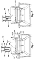
- FIG. 1 shows the normal rest condition. Sterility is maintained inside, especially of the needle 708, by the sealed closure 712.
- the guide tube 704 is advanced through the outer sleeve so that its forward end cuts and deflects the foil 712 out of the path of the needle ( Figure 2).
- the needle carrier 706 at the time advances with the guide tube 704.
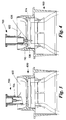
- the advance of the guide tube 704 is then continued, downwardly into the throat 622 of the overcap 600 of the culture bottle ( Figure 3).
- Advance of the guide tube 704 then ceases, and instead the needle carrier 706 is advanced through the guide tube.
- the forward end portion 710 of the needle carrier 706 enters the aperture in the guide tab 626 at the bottom of the overcap throat 622, ensuring correct registration of the venting needle 708, which pierces the septum of the closure 614 of the culture bottle ( Figure 4). Excess pressure in the bottle is thus safely relieved.
- the guide tube 704 is then retracted upwardly (Figure 5) back to its starting position ( Figure 6), leaving the needle carrier 706 in position in the throat 622 of the overcap 600, with the needle 708 penetrating the bottle septum.
- the needle carrier 706 is accommodated within the depth of the overcap throat 622.
- the spent outer sleeve and guide tube assembly is then disposed of.
- the needle carrier and needle are disposed of with the culture bottle after testing and examination have been completed.
- venting device The most important point to note about the venting device is that sterility of the needle 708 is maintained substantially up to the moment of penetration of the bottle closure septum.
- the use of the guide tube 704 to cut and deflect the foil 712 ensures that the needle does not contact this foil during its downward movement.
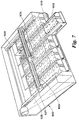
- Figure 7 shows an embodiment of culture bottle monitoring apparatus comprising a stationary flat bed in which a plurality of bottles are located, and a movable laser arranged repeatedly to scan the bottles in turn.
- the flat bed 1002 which may comprise one drawer of an incubation cabinet, comprises five similar supports 1008, each slidably received therein and independently removable therefrom.
- Each support 1008 comprises two apertured aluminium blocks defining two side by side rows of ten similar recesses 1010, each for receiving a respective culture bottle (not shown).
- the bed 1002 further comprises a laser 1024 (e.g. a Matsushita LA40 laser) mounted for movement in two perpendicular directions (X and Y) on a generally conventional X - Y motion controller.
- the controller comprises a cross-rail 1026 on which laser 1024 is mounted for sliding movement in an X direction under the action of a stepper-motor driven belt drive 1027.
- the ends of rail 1024 are carried by stepper-motor driven belt drives 1028, for causing movement in a Y direction.
- sample containing bottles are loaded into recesses 1010.
- the laser performs a scanning cycle once every five minutes. Scanning a full bed takes about two and a half minutes. This is followed by a rest period of two and a half minutes for a full bed.
- the results of each scan of each bottle are conveyed to a computer control means for suitable processing and display on a VDU if appropriate. When a positive result is detected for a particular bottle, this information is made available to an operator, e.g. by a suitable message on the VDU.
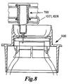
- the drive mechanism 1026, 1027, 1028 of the scanner 1024 may be used to move a venting device to the particular bottle to be vented.
- the venting device possibly together with a mechanism for effecting automatic operation thereof, can be carried by the laser 1024, and utilised during the two and a half minute rest period of the laser. This is a practicable procedure because only a very small proportion of the culture bottles in the bed will require venting.
- the venting mechanism may carry a small stack, say five, disposable venting devices, and the computer may monitor the stack level and call for replacements as necessary.
- the venting mechanism includes a drive for operating the venting device.
- a drive for operating the venting device.
- One possible drive is a lead screw which firstly acts on the guide tube to move it through the outer sleeve (which is held fixed on the laser) and secondly acts on a plunger to move the needle carrier through the guide tube after the latter has been engaged against a stop or a limit switch has operated.
- a passive drive for the needle carrier is used, wherein the second function of the lead screw is to lower a loading weight on to the needle carrier.
- the lead screw is a reversible drive to lift the outer sleeve and guide tube, and if used the loading weight, back to the start position after the needle has pierced the bottle closure septum. All the motorised actions are preferably controlled by limit switches. Additionally, the complete operating sequence is microchip controlled under the supervision of the computer.
Landscapes
- Health & Medical Sciences (AREA)
- Chemical & Material Sciences (AREA)
- Wood Science & Technology (AREA)
- Zoology (AREA)
- Engineering & Computer Science (AREA)
- Bioinformatics & Cheminformatics (AREA)
- Organic Chemistry (AREA)
- Life Sciences & Earth Sciences (AREA)
- Biotechnology (AREA)
- Genetics & Genomics (AREA)
- Biomedical Technology (AREA)
- Microbiology (AREA)
- Biochemistry (AREA)
- General Engineering & Computer Science (AREA)
- General Health & Medical Sciences (AREA)
- Sustainable Development (AREA)
- Clinical Laboratory Science (AREA)
- Analytical Chemistry (AREA)
- Apparatus Associated With Microorganisms And Enzymes (AREA)
- External Artificial Organs (AREA)
- Massaging Devices (AREA)
- Arc Welding In General (AREA)
Abstract
Description
- This invention relates to a venting device, and in particular to a venting device for a culture bottle having a seal incorporating a septum.
- When cultures are grown in a microbiological laboratory to test specimens, exampled by blood cultures, it can happen that, due to organism growth, substantial pressure develops inside the culture bottle. Sometimes, positive pressure can build up to the point where danger is involved and, in this case, the only alternative to disposing of the bottle, with consequent loss of the specimen, is to vent the bottle. In the latter case, however, it is necessary to ensure that venting does not lead to erroneous results due to the introduction of extraneous organisms into the bottle by the venting process.
- According to the present invention, in its broadest aspect, there is provided a venting device for a culture bottle having a septum, comprising a needle carrier having a venting volume in communication with a needle, and a membrane-carrying structure within which the needle carrier and needle are movably sealed, the arrangement being such that the device is operable, when positioned with the membrane between the needle and the septum, firstly to move the membrane away from its position between the needle and the septum and secondly to move the needle to pierce the septum in order to vent excess volume into the venting volume.
- The membrane-carrying structure preferably comprises an outer sleeve closed at one end by a frangible membrane, and a guide tube axially slidable through the outer sleeve, for cutting and deflecting the membrane out of the path of the needle carrier, the device having an unused rest condition in which the forward end of the guide tube is retracted behind the membrane and the forward end of the needle is retracted behind the forward end of the guide tube, an intermediate operational condition in which the guide tube has been moved forwardly to cut and deflect the membrane out of the path of the needle, and a final operational condition in which the needle carrier has been moved forwardly through the guide tube, in use to enable the needle to penetrate the septum of the culture bottle and vent the bottle to the interior of the needle carrier behind the needle.
- The above-defined venting device thus provides a means of venting whereby, assuming the needle to be aseptic within the device prior to use, this asepticity is substantially maintained right up to the moment of penetration of the bottle septum. Avoidance of contact of the needle with the membrane, e.g. a metallic foil, closing the outer sleeve of the device is most important to this end.
- Preferably, therefore, the interior of the needle carrier behind the needle contains a microbiologically effective filter for assisting the prevention of movements of organisms into or out of the bottle.
- In order to maintain the integrity of the culture bottle, the needle carrier is preferably releasable out of the forward end of the guide tube, whereby in use the needle remains in place extending through the septum of the culture bottle. The venting device is thus preferably in the form of a sterile package, the outer sleeve and guide tube being disposable after use and the needle carrier and needle being disposable with the culture bottle when microbiological testing has been completed. The package may be rendered aseptic by an irradiation process.
- Features of the culture bottle are important in relation to use of the above-described venting device.
- According to another aspect of the invention, therefore, there is provided, in combination with the venting device, an overcap for the culture bottle which has an entry throat in which the needle carrier is accommodated when the needle is left extending through the septum of the culture bottle. The entry throat of the overcap preferably carries an axial guide for a part of the needle carrier of reduced cross section in which the needle is mounted.
- According to still another aspect of the invention, there is provided culture bottle examination apparatus which includes means for detecting pressure variations in the bottle, a venting device as heretofore defined, and means for operating the above-defined venting device if an excess bottle pressure is detected.
- Conveniently, said examination apparatus may comprise a multi-bottle carrier for a plurality of culture bottles, means for repeatedly scanning the bottles to detect pressure variations in the bottles, and means for moving a venting device into an operating position at any bottle at which an excess pressure is detected. In this apparatus, it is preferred if the scanning mechanism for a pressure detecting means is also employed to move a venting mechanism incorporating the venting device to a bottle requiring venting.
- The complete venting mechanism also may incorporate a motorised drive for operating the venting device in the manner hitherto described, and also a magazine or carrier for replacing a spent venting device with a fresh one.
- An example of apparatus for monitoring the growth of micro-organisms in culture bottles, comprising examination apparatus as aforesaid, is claimed and described in Patent Application No. PCT/GB92/01327 (WO 93/03178).
- An embodiment of venting device in accordance with the invention is now exemplified in the following description, making reference to the accompanying drawings, in which:-
- Figures 1 to 6 show a preferred embodiment of venting device in six successive stages of operation;
- Figure 7 shows a culture bottle monitoring apparatus in which the venting device may be incorporated; and
- Figure 8 shows the manner in which a venting device may be incorporated in the apparatus of Figure 7.
- Referring first to Figures 1 to 6, there is shown the top of a culture bottle fitted with a bottle seal incorporating a septum and with an
overcap 600 from which a tamper-evident tear-off portion has been removed. This overcap is claimed and described in more detail in European Patent Application No. 94906281.4 (WO 94/19452). - The illustrated
overcap 600 has all round a generally squarelateral projection 606 which is relatively thin, so that the body of the cap hascylindrical sections cylindrical section 610 has internally alip 612 which snap-fits over thebottle seal 614. - The upper surface of the
projection 606 is on one side marked with a barcode for bottle identification purposes, and on the opposite side, adjacent one corner, has a port at which, when the bottle is in use in an incubation carrier, an LED uniquely associated with each particular bottle cap can be viewed. Thus, an LED may operate if excess pressure develops in the bottle. Safe and easy handling, even by an operator wearing gloves, is facilitated by the squarelateral projection 606, and the LED port imparts a tactile and visible asymmetry which facilitates replacement of the bottle in the correct orientation, e.g. for reading of the barcode, which uniquely identifies the bottle independently of its position in the carrier. - Internally, as shown in the drawings, the
overcap 600 has an innerdependent sleeve 620 within the lower outercylindrical section 610. Thelip 612 which snap-fits over thebottle seal 614 is provided at the bottom of thisinner sleeve 620. - Above the inner sleeve, the upper
cylindrical section 608 is formed internally with a relativelydeep throat 622, which at the bottom is terminated by a curved, inwardly and downwardly directeddeformable lip 624 which engages the top of the bottle seal, taking up manufacturing tolerances. Thedeep throat 622, in conjunction with the squarelateral projection 606, reduces risk of "needle-stick" injuries when a hypodermic syringe is used, for example to sample the bottle contents. Also adjacent the bottom of thethroat 622, thecap 600 is formed internally with anapertured tab 626 which constitutes a guide for the needle of a bottle venting device in accordance with the present invention. - The venting device, generally referenced 700, is used to vent the culture bottle if an excess and possibly dangerous pressure develops in the bottle during use, e.g. incubation in an incubation carrier.
- The venting device comprises an
outer sleeve 702, aguide tube 704 slidable in the outer sleeve, aneedle carrier 706 slidable in the guide tube, and ashort needle 708 mounted in a forward (bottom)end portion 710 of the needle carrier which is of reduced cross-section. In the rest condition of the device, shown in Figure 1, the forward (bottom) end of theouter sleeve 702 is sealed closed by a membrane such as ametallic foil 712. - The entire venting device constitutes a small disposable package, entirely moulded of plastics material except for the needle. The package, and in particular the interior thereof, is rendered sterile by irradiation. Moreover, behind the needle, the interior of the
needle carrier 706 accommodates a microbiologically effective filter element (not shown) to contain aerosols and prevent movement of micro-organisms either into or out of the culture bottle during venting. - The venting device is shown in various stages of operation in Figures 1 to 6. Figure 1, as stated, shows the normal rest condition. Sterility is maintained inside, especially of the
needle 708, by the sealedclosure 712. - In operation, first the
guide tube 704 is advanced through the outer sleeve so that its forward end cuts and deflects thefoil 712 out of the path of the needle (Figure 2). Theneedle carrier 706 at the time advances with theguide tube 704. The advance of theguide tube 704 is then continued, downwardly into thethroat 622 of theovercap 600 of the culture bottle (Figure 3). Advance of theguide tube 704 then ceases, and instead theneedle carrier 706 is advanced through the guide tube. Theforward end portion 710 of theneedle carrier 706 enters the aperture in theguide tab 626 at the bottom of theovercap throat 622, ensuring correct registration of theventing needle 708, which pierces the septum of theclosure 614 of the culture bottle (Figure 4). Excess pressure in the bottle is thus safely relieved. - The
guide tube 704 is then retracted upwardly (Figure 5) back to its starting position (Figure 6), leaving theneedle carrier 706 in position in thethroat 622 of theovercap 600, with theneedle 708 penetrating the bottle septum. Theneedle carrier 706 is accommodated within the depth of theovercap throat 622. The spent outer sleeve and guide tube assembly is then disposed of. The needle carrier and needle are disposed of with the culture bottle after testing and examination have been completed. - The most important point to note about the venting device is that sterility of the
needle 708 is maintained substantially up to the moment of penetration of the bottle closure septum. In particular, the use of theguide tube 704 to cut and deflect thefoil 712 ensures that the needle does not contact this foil during its downward movement. - Figure 7 shows an embodiment of culture bottle monitoring apparatus comprising a stationary flat bed in which a plurality of bottles are located, and a movable laser arranged repeatedly to scan the bottles in turn.
- The
flat bed 1002, which may comprise one drawer of an incubation cabinet, comprises fivesimilar supports 1008, each slidably received therein and independently removable therefrom. Eachsupport 1008 comprises two apertured aluminium blocks defining two side by side rows of tensimilar recesses 1010, each for receiving a respective culture bottle (not shown). - The
bed 1002 further comprises a laser 1024 (e.g. a Matsushita LA40 laser) mounted for movement in two perpendicular directions (X and Y) on a generally conventional X - Y motion controller. The controller comprises a cross-rail 1026 on whichlaser 1024 is mounted for sliding movement in an X direction under the action of a stepper-motor drivenbelt drive 1027. The ends ofrail 1024 are carried by stepper-motor drivenbelt drives 1028, for causing movement in a Y direction. - In use, sample containing bottles are loaded into
recesses 1010. In normal use, the laser performs a scanning cycle once every five minutes. Scanning a full bed takes about two and a half minutes. This is followed by a rest period of two and a half minutes for a full bed. The results of each scan of each bottle are conveyed to a computer control means for suitable processing and display on a VDU if appropriate. When a positive result is detected for a particular bottle, this information is made available to an operator, e.g. by a suitable message on the VDU. - Further and more complete details of the monitoring apparatus of Figure 7 can be found in Patent Application No. PCT/GB92/01327 (WO93/03178).
- If an indication is given on the VDU that an excess pressure has developed in one of the culture bottles, possibly also identified at the LED associated with each bottle overcap, it is appropriate for safety reasons to use the venting device of the present invention to vent the bottle in question and relieve the excess pressure.
- Conveniently, as indicated in Figure 8, the
drive mechanism scanner 1024 may be used to move a venting device to the particular bottle to be vented. In practice, the venting device, possibly together with a mechanism for effecting automatic operation thereof, can be carried by thelaser 1024, and utilised during the two and a half minute rest period of the laser. This is a practicable procedure because only a very small proportion of the culture bottles in the bed will require venting. Thus, the venting mechanism may carry a small stack, say five, disposable venting devices, and the computer may monitor the stack level and call for replacements as necessary. - In addition to a magazine or carrier for replacing a spent venting device, the venting mechanism includes a drive for operating the venting device. One possible drive is a lead screw which firstly acts on the guide tube to move it through the outer sleeve (which is held fixed on the laser) and secondly acts on a plunger to move the needle carrier through the guide tube after the latter has been engaged against a stop or a limit switch has operated. In a modification, a passive drive for the needle carrier is used, wherein the second function of the lead screw is to lower a loading weight on to the needle carrier. The lead screw is a reversible drive to lift the outer sleeve and guide tube, and if used the loading weight, back to the start position after the needle has pierced the bottle closure septum. All the motorised actions are preferably controlled by limit switches. Additionally, the complete operating sequence is microchip controlled under the supervision of the computer.
Claims (11)
- A venting device for a culture bottle having a septum, comprising a needle carrier (706) having a venting volume in communication with a needle (708), and a membrane-carrying structure (702) within which the needle carrier and needle are movably sealed, the arrangement being such that the device is operable, when positioned with the membrane (712) between the needle (708) and the septum, firstly to move the membrane away from its position between the needle and the septum and secondly to move the needle to pierce the septum in order to vent excess volume into the venting volume.
- A venting device according to claim 1, wherein the membrane-carrying structure comprises an outer sleeve (702) and the needle carrier (706) is slidable through a guide tube (704) slidable through the outer sleeve (702) to move the membrane (712) and to enable movement of the needle carrier (706) through the guide tube (704) to pierce the septum.
- A venting device according to claim 2, wherein the outer sleeve (702) is closed at one end by a frangible membrane (712), and the device has an unused rest condition in which the forward end of the guide tube (704) is retracted behind the membrane (712) and the forward end of the needle (708) is retracted behind the forward end of the guide tube (704), an intermediate operational condition in which the guide tube has been moved forwardly to cut and deflect the membrane (712) out of the path of the needle, and a final operational condition in which the needle carrier (706) has been moved forwardly through the guide tube (704), in use to enable the needle (708) to penetrate the septum of the culture bottle and vent the bottle to the interior of the needle carrier behind the needle.
- A venting device as claimed in claim 3, wherein the interior of the needle carrier (706) behind the needle contains a microbiologically effective filter for assisting the prevention of movements of organisms into or out of the bottle.
- A venting device as claimed in claim 3 or 4, wherein the needle carrier is releasable out of the forward end of the guide tube, whereby in use the needle remains in place extending through the septum of the culture bottle.
- A venting device as claimed in claim 5, in the form of a sterile package, the outer sleeve and guide tube being disposable after use and the needle carrier and needle being disposable with the culture bottle when microbiological testing has been completed.
- A venting device as claimed in claim 5 or 6, in combination with an overcap (600) for the culture bottle which has an entry throat (622) in which the needle carrier is accommodated when the needle is left extending through the septum of the culture bottle.
- The combination claimed in claim 7, wherein the entry throat of the overcap carries an axial guide (626) for a part of the needle carrier of reduced cross section in which the needle is mounted.
- Culture bottle examination apparatus which includes means for detecting pressure variations in the bottle, a venting device in accordance with any of claims 1 to 8, and means for operating the venting device if an excess bottle pressure is detected.
- Examination apparatus as claimed in claim 9, comprising a multibottle carrier (1002,1009) for a plurality of culture bottles, means (1024) for repeatedly scanning the bottles to detect pressure variations in the bottles, and means (1026,1027,1028) for moving a venting device into an operating position at any bottle at which an excess pressure is detected.
- Examination apparatus as claimed in claim 10, in which the scanning mechanism for a pressure detecting means is also employed to move the venting device to a bottle requiring venting.
Priority Applications (1)
| Application Number | Priority Date | Filing Date | Title |
|---|---|---|---|
| EP94906280A EP0684985B1 (en) | 1993-02-17 | 1994-02-09 | Venting device |
Applications Claiming Priority (4)
| Application Number | Priority Date | Filing Date | Title |
|---|---|---|---|
| EP93301172 | 1993-02-17 | ||
| EP93301172 | 1993-02-17 | ||
| EP94906280A EP0684985B1 (en) | 1993-02-17 | 1994-02-09 | Venting device |
| PCT/GB1994/000255 WO1994019451A1 (en) | 1993-02-17 | 1994-02-09 | Venting device |
Publications (2)
| Publication Number | Publication Date |
|---|---|
| EP0684985A1 EP0684985A1 (en) | 1995-12-06 |
| EP0684985B1 true EP0684985B1 (en) | 1997-07-02 |
Family
ID=8214308
Family Applications (1)
| Application Number | Title | Priority Date | Filing Date |
|---|---|---|---|
| EP94906280A Expired - Lifetime EP0684985B1 (en) | 1993-02-17 | 1994-02-09 | Venting device |
Country Status (5)
| Country | Link |
|---|---|
| EP (1) | EP0684985B1 (en) |
| AU (1) | AU6004294A (en) |
| CA (1) | CA2156278A1 (en) |
| DE (1) | DE69404023T2 (en) |
| WO (1) | WO1994019451A1 (en) |
Families Citing this family (4)
| Publication number | Priority date | Publication date | Assignee | Title |
|---|---|---|---|---|
| US6436349B1 (en) | 1991-03-04 | 2002-08-20 | Bayer Corporation | Fluid handling apparatus for an automated analyzer |
| GB9609563D0 (en) * | 1996-05-08 | 1996-07-10 | Sterimatic Holdings Ltd | Venting devices |
| WO1997047728A1 (en) * | 1996-06-11 | 1997-12-18 | Oxoid Limited | Monitoring the contents of sealed containers |
| CN116716166B (en) * | 2023-06-13 | 2024-03-29 | 珠海美华医疗科技有限公司 | Splash-proof cap for sampling positive blood culture bottle and sampling method |
Family Cites Families (5)
| Publication number | Priority date | Publication date | Assignee | Title |
|---|---|---|---|---|
| FR2029242A5 (en) * | 1969-01-21 | 1970-10-16 | Alriq Christian | Self-perforable plug for bacteriological - culture tubes |
| CH603168A5 (en) * | 1975-03-21 | 1978-08-15 | Dematex Dev & Invest | |
| US4416984A (en) * | 1981-05-22 | 1983-11-22 | Concord Laboratories, Inc. | Sterilization indicator |
| US4808381A (en) * | 1983-05-13 | 1989-02-28 | E. I. Du Pont De Nemours And Company | Fluid transfer device |
| US5051360A (en) * | 1988-05-06 | 1991-09-24 | Abo, Inc. | Method for detecting microorganism activity |
-
1994
- 1994-02-09 CA CA 2156278 patent/CA2156278A1/en not_active Abandoned
- 1994-02-09 WO PCT/GB1994/000255 patent/WO1994019451A1/en not_active Ceased
- 1994-02-09 EP EP94906280A patent/EP0684985B1/en not_active Expired - Lifetime
- 1994-02-09 DE DE69404023T patent/DE69404023T2/en not_active Expired - Fee Related
- 1994-02-09 AU AU60042/94A patent/AU6004294A/en not_active Abandoned
Also Published As
| Publication number | Publication date |
|---|---|
| EP0684985A1 (en) | 1995-12-06 |
| CA2156278A1 (en) | 1994-09-01 |
| DE69404023D1 (en) | 1997-08-07 |
| WO1994019451A1 (en) | 1994-09-01 |
| DE69404023T2 (en) | 1998-01-08 |
| AU6004294A (en) | 1994-09-14 |
Similar Documents
| Publication | Publication Date | Title |
|---|---|---|
| EP0391461B1 (en) | Stopper of analysis test tubes | |
| CN100370950C (en) | Lancet, lancing device and method for driving a lancet of the lancing device | |
| JP3683268B2 (en) | Liquid injection device | |
| US6913580B2 (en) | Method of body fluid specimen collection | |
| US6616616B2 (en) | Lancet system | |
| US5666967A (en) | Fluid sample collection and introduction device | |
| EP0206166A1 (en) | Self-contained indicator device | |
| AU2008332708B2 (en) | Device and method for microbiological analysis of biological samples | |
| US6171293B1 (en) | Venting devices | |
| US4596773A (en) | Sterilization indicator | |
| US4850996A (en) | Safety needle | |
| EP2148823B1 (en) | A sealing cap for a body fluid container and a blood collection device | |
| EP0543982B1 (en) | Demountable, replaceable aspirating needle cartridge assembly | |
| US20050252572A1 (en) | Automated use of a vision system to detect foreign matter in reconstituted drugs before transfer to a syringe | |
| CN112203586B (en) | Sample collection device, system and method for extracting and collecting user's body fluid sample | |
| WO1995011083A3 (en) | Reaction tube and method of use to minimize contamination | |
| CA2124705C (en) | Liquid specimen collector with removable extraction device | |
| EP0249994A2 (en) | Device for taking from a vein samples of blood to be tested | |
| WO1994019451A1 (en) | Venting device | |
| US5628353A (en) | Method and device for withdrawing a liquid from a sealed glass ampoule | |
| EP0684986B1 (en) | Caps for culture bottles | |
| US7815621B2 (en) | Recovery system | |
| CN114460316A (en) | Storage tube, sample introduction device and sample introduction method | |
| EP1732808A2 (en) | Device for reconstituting a drug vial and medication dose underfill detection system for application in an automated syringe preparing system | |
| CN114931442B (en) | A device for automatically handling sharp objects |
Legal Events
| Date | Code | Title | Description |
|---|---|---|---|
| PUAI | Public reference made under article 153(3) epc to a published international application that has entered the european phase |
Free format text: ORIGINAL CODE: 0009012 |
|
| 17P | Request for examination filed |
Effective date: 19950728 |
|
| AK | Designated contracting states |
Kind code of ref document: A1 Designated state(s): DE ES FR GB IT SE |
|
| 17Q | First examination report despatched |
Effective date: 19960507 |
|
| GRAG | Despatch of communication of intention to grant |
Free format text: ORIGINAL CODE: EPIDOS AGRA |
|
| GRAH | Despatch of communication of intention to grant a patent |
Free format text: ORIGINAL CODE: EPIDOS IGRA |
|
| GRAH | Despatch of communication of intention to grant a patent |
Free format text: ORIGINAL CODE: EPIDOS IGRA |
|
| GRAA | (expected) grant |
Free format text: ORIGINAL CODE: 0009210 |
|
| AK | Designated contracting states |
Kind code of ref document: B1 Designated state(s): DE ES FR GB IT SE |
|
| PG25 | Lapsed in a contracting state [announced via postgrant information from national office to epo] |
Ref country code: IT Free format text: LAPSE BECAUSE OF FAILURE TO SUBMIT A TRANSLATION OF THE DESCRIPTION OR TO PAY THE FEE WITHIN THE PRESCRIBED TIME-LIMIT;WARNING: LAPSES OF ITALIAN PATENTS WITH EFFECTIVE DATE BEFORE 2007 MAY HAVE OCCURRED AT ANY TIME BEFORE 2007. THE CORRECT EFFECTIVE DATE MAY BE DIFFERENT FROM THE ONE RECORDED. Effective date: 19970702 Ref country code: FR Free format text: THE PATENT HAS BEEN ANNULLED BY A DECISION OF A NATIONAL AUTHORITY Effective date: 19970702 Ref country code: ES Free format text: THE PATENT HAS BEEN ANNULLED BY A DECISION OF A NATIONAL AUTHORITY Effective date: 19970702 |
|
| REF | Corresponds to: |
Ref document number: 69404023 Country of ref document: DE Date of ref document: 19970807 |
|
| RAP2 | Party data changed (patent owner data changed or rights of a patent transferred) |
Owner name: UNIPATH LIMITED Owner name: OXOID LIMITED |
|
| ET | Fr: translation filed | ||
| PG25 | Lapsed in a contracting state [announced via postgrant information from national office to epo] |
Ref country code: SE Effective date: 19971002 |
|
| PG25 | Lapsed in a contracting state [announced via postgrant information from national office to epo] |
Ref country code: GB Free format text: LAPSE BECAUSE OF NON-PAYMENT OF DUE FEES Effective date: 19980209 |
|
| PLBE | No opposition filed within time limit |
Free format text: ORIGINAL CODE: 0009261 |
|
| STAA | Information on the status of an ep patent application or granted ep patent |
Free format text: STATUS: NO OPPOSITION FILED WITHIN TIME LIMIT |
|
| 26N | No opposition filed | ||
| GBPC | Gb: european patent ceased through non-payment of renewal fee |
Effective date: 19980209 |
|
| PG25 | Lapsed in a contracting state [announced via postgrant information from national office to epo] |
Ref country code: DE Free format text: LAPSE BECAUSE OF NON-PAYMENT OF DUE FEES Effective date: 19981103 |
|
| REG | Reference to a national code |
Ref country code: FR Ref legal event code: ST |
|
| REG | Reference to a national code |
Ref country code: GB Ref legal event code: 732E |